

Page 1
VISION CREATIVE, INC.
중구 남대문로 5가 526
대우재단빌딩 16층
담 당 김세호님 TEL
MODEL
CCR-23SR,49DR,72TR/WCC-23SR/WCR-23SR/CCR-23SF,49DF,72TF/WCR-23SF
BUYER
1차 03.2.7 6차
2차 03.2.13 7차
일정 3차 03.7.22 8차
4차 03.7.25 9차
5차 03.7.28 10차
제판 03.7.28(Han)출력
인인쇄쇄
규격
MEMO
03.12.15-3page-수정 (6)추가
연연락락처처
VVIISSIIOONN
담담 당당
박선민
TEL: 757-9340 FAX: 7741039
Page 2
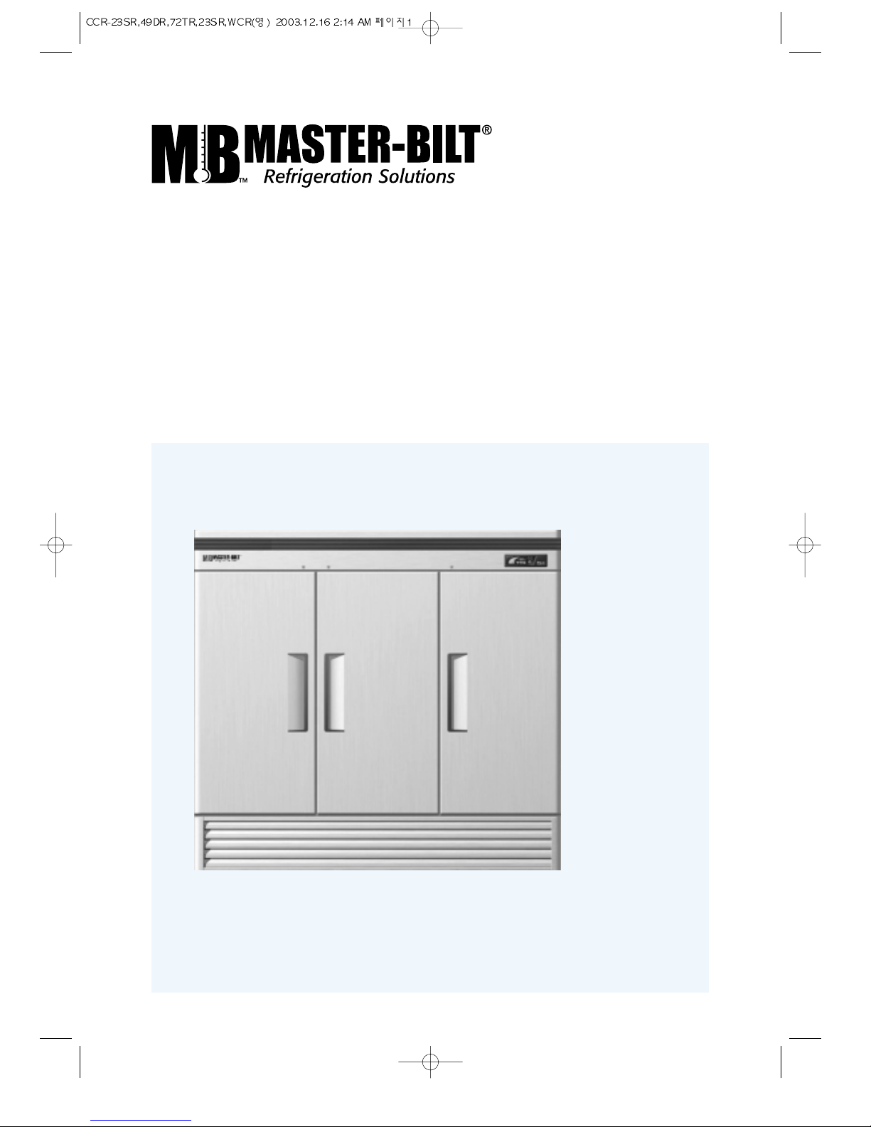
Refrigerator
Freezer
Installation and Operation Manual
Please read this manual completely before attempting to install or operate this equipment!
Full Stainless Steel Visible Exterior
Refrigerator
CCR-23SR
CCR-49DR
CCR-72TR
WCC-23SR
WCR-23SR
Freezer
CCR-23SF
WCR-23SF
CCR-49DF
CCR-72TF
Page 3
1. SPECIFICATION
..........................................................................................
2
2. SERIAL NUMBER
........................................................................................
2
3. INSTALLATION ............................................................................................ 3
4. CLEANING & CAUTION
..............................................................................
4
5. BASIC OPERATION
5-1. REFRIGERATORS........................................................................... 5~9
5-2. FREEZERS................................................................................... 10~14
6. INSTALLATION METHOD OF REVERSE DOOR
................................
15~16
7. BEFORE REQUESTING SERVICE
............................................................
17
8. WARRANTY
................................................................................................18
9. TERMS OF SALE........................................................................................19
2
CONTENTS
PAGE
The serial number is located on the data label inside.
Please retain the unit’s serial number for service purpose.
SERIAL NUMBER
Refrigerators
SPECIFICA TION
MODEL COMP H.P . V/Hz REFRIGERANT AMPS WEIGHT
CCR-23SR
1/4 1 15V/60Hz R-134a 5.5A 265lbs
CCR-49DR
1/3 1 15V/60Hz R-134a 9.2A 397lbs
CCR-72TR
2/3 1 15V/60Hz R-134a 1 1A 530lbs
WCC-23SR
1/4 1 15V/60Hz R-404a 9.0A 265lbs
WCR-23SR
1/4 1 15V/60Hz R-404a 9.0A 265lbs
Freezers
MODEL COMP H.P. V/Hz REFRIGERANT AMPS WEIGHT
CCR-23SF
1/2 1 15V/60Hz R-404a 8.7A 265lbs
CCR-49DF
3/4 1 15V/60Hz R-404a 10.5A 397lbs
CCR-72TF
5/4
1 15V/208~220V/60Hz
R-404a 10A 540lbs
WCR-23SF
1/2 1 15V/60Hz R-404a 8.7A 265lbs
Page 4

3
1. GOOD AIR CIRCULA TION
- Avoid any partitions or objects which may restrict air flow.
- Be sure there is sufficient air space to allow air flow at the rear of the unit.
2. DO NOT PLACE NEAR HEA T
- High ambient temperature will adversly affect cooling efficiency.
3. INDOOR USAGE ONL Y
- Be sure to install this unit indoors.
4. ST ABILIZING
- While in use, make sure the front wheels are locked to keep the unit in place.
5. LEVELING
- Be sure that the unit is level from the front to the back and side to side.
6. UNIT SHOULD BE ON DEDICA TED OUTLET.
INST ALLATION
Page 5

4
1. CLEANING THE INTERIOR AND EXTERIOR
- The interior and exterior of the unit can be cleaned using warm water with soap.
- Do not use an abrasive cleaner because it will scratch the stainless steel surface.
2. CLEANING THE CONDENSER FINS
- To maintain proper refrigeration performance, the Condensing coil must be free of
dust, dirt and grease.
This will require periodic cleaning. Condenser fins should be cleaned at least every
three months (90 days) or as needed.
3. CLEAN THE GASKET
- The door gasket should be cleaned frequently to maintain proper sealing.
4. CHECK AFTER CLEANING
- Check the unit again for safety .
- Check that the unit is operating properly .
1. POWER CORD
- Be sure that the power cord is connected to the proper voltage.
- A protected circuit of the correct voltage and amperage must be run for connection of
the line cord.
- Turn ‘off’ the power switch before disconnecting the power cord, whenever
performing maintenance functions or cleaning the refrigerated
cabinet.
- Dual voltage freezer (CCR-72TF) requires receptacle as the right
sides.
- Compressor warranties are void if compressor burns out due to low
voltage.
2. RE-ST ARTING
- If disconnected, wait 5 minutes before re-starting.
CAUTION
WH
E
BK RD
CLEANING
Page 6
5
BASIC OPERA TION
WCC-23SR
WCR-23SR
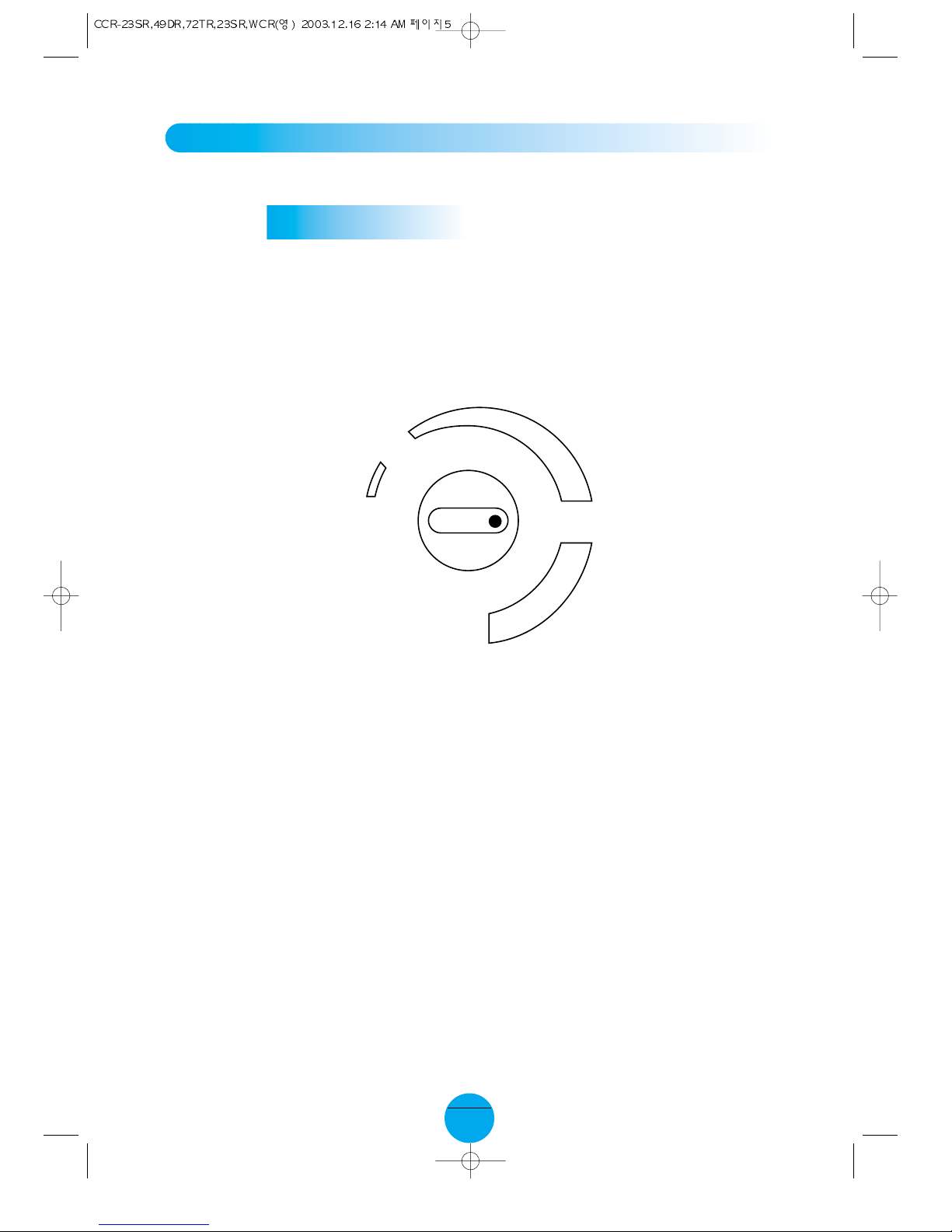
1. The controller(thermostat) is located at the top inside of the unit.
2. The factory setting for the control is ‘Normal’, and maintains about 38˚F (3˚C) inside.
3. Set toward “Cool” for higher temperature and “Cold” for lower temperature.
4. The thermostat controls compressor’s cycling by sensing inside temperature.
5. Interior light is activated by the door switch when door is opened.
6. Cooling fans are activated by the door switch when door is completely closed.
REFRIGERA T OR
OFF
COOL
COLD
NORMAL
T emperature Controller
(Thermostat)
Page 7

6
BASIC OPERA TION
CCR-23SR
CCR-49DR
CCR-72TR
1. Plug in and turn on the power switch located on the bottom of the top grille right side.
The Display panel will be lighted and make a beep sound. The compressor will begin
to run.
2. The default temperature setting is No. “5”.
3. The compressor is automatically cycled by the electronic controller (PCB, D-Sensor).
4. The Defrost cycle is automatically controlled by the R-sensor and the PCB.
5. Set level toward “1” for higher temperature and toward “9” for lower temperature.
6. The interior light is activated by the rocker switch at the bottom of the top grille when
the door is opened.
7. Evaporator fan motor(s) will run after all doors are completely closed.
REFRIGERA T ORS
Page 8

7
DISPLAY P ANEL OF REFRIGERATOR
9
TEMPERATURE Q.C.
8
7
6
5
4
3
2
1
FAN DOOR
QUICK COOLING
TEMPERATURE
˚F
TEMP. SETTING
QUICK COOLING
BUTTON
TEMP. CONTROL BUTTON
(SEE TO PAGE 8)
INNER TEMP.
(SEE TO PAGE 9)
(SEE TO PAGE 8)
QUICK COOLING
INDICATOR
FAN RUNNING
INDICATOR
DOOR OPENING
INDICATOR
Page 9

8
1. If you push the Q.C. (Quick Cooling) button, the compressor will run continuously until
D-Senser detect 14˚F (-10˚C) to bring down the temperature more quickly.
(max.comp.run time = 120 min.)
2. If you push the Q.C. button again during Quick Cooling mode, the compressor will
return to the normal operation.
3. During the Quick Cooling mode, the temperature Up/Down button will not affect the
compressor’s operation.
1. By pushing the up/down button, you can set the inside temperature level from ‘1’ to
‘9’.
2. If you want lower temperature, push the Down button to be lighted higher level
numbers.
QUICK COOLING
UP/DOWN BUTTON (Temperature control button)
Page 10

9
1. It displays inside temperature.
2. Display range is 14˚F to 69˚F (-10˚C ~ +20˚C).
3. When inside temperature is lower than 14˚F, the panel will display ‘ ’.
and, higher than 69˚F, the panel will display ‘ ’.
1. If the fan motor is running, fan running indicator will be turned on.
2.
Evaporator fan motor is activated when the door (both doors for CCR-49DR, all three
doors for CCR-72TR) is closed.
1. If any door is opened, door opening indicator will be turned on.
2. In case that any door was opened around 30 seconds, warning beep sound will be
ring three (3) times.
3. In case of passing around 1 minute, warning beep sound will be ring again five (5)
times.
4. In case of passing around 5 minutes, the beep sound will be ring continuously.
5. On all the conditions good, the beep sound will stop immediately if the door closed
properly .
INNER TEMPERA TURE DISPLAY
F AN RUNNING INDICATOR
DOOR OPENING INDICA T OR
Page 11

10
BASIC OPERA TION
CCR-23SF
CCR-49DF
CCR-72TF
WCR-23SF
1. Plug in and turn on the power switch located on the bottom of the top grille right side.
The Display panel will be lighted and make a beeping sound. The compressor will
begin to run.
2. The default temperature setting is No. “5”.
3. The compressor is automatically cycled by the electronic controller (PCB, F-Sensor).
4. The Defrost cycle is automatically controlled by the D-sensor, and the PCB.
5. Set toward “1” for higher temperatures and toward “9” for lower temperatures.
6. The interior light is activated by the door switch at the bottom of the top grille when
the door is opened.
7. Evaporator fan motor(s) will run after all doors are completely closed.
8. Good Air Flow in freezer unit is critical.
Be careful to load product so that it neither presses against the back wall, nor reaches
within four inches from the evaporator compartment.
FREEZERS
Page 12

11
DISPLAY P ANEL OF FREEZER
9
TEMPERATURE D.F.
8
7
6
5
4
3
2
1
FAN DOOR
MANUAL DEFROST
TEMPERATURE
˚F
TEMP. SETTING
MANUAL DEFROST
INDICATOR
FAN RUNNING
INDICATOR
DOOR OPENING
INDICATOR
MANUAL DEFROST
BUTTON
TEMP. CONTROL BUTTON
(SEE TO PAGE 12~13)
INNER TEMP.
(SEE TO PAGE 14)
(SEE TO PAGE 12~13)
Page 13

12
1. If you push MANUAL DEFROST button for 5 seconds, the Defrost will start.
2. During the Manual Defrost mode, the Up/Down button for the temp. control can not
make the compressor cycle ON or OFF.
3. If you want to change the Manual Defrost mode in the normal mode. push MANUAL
DEFROST button for 5 seconds.
1. By pushing the Up/Down button, you can set the inside temperature level from “1” to
“9”.
2. If you want to lower /temperature, push the button to lower the indicator to higher
level numbers.
1. The electronic defrost controller is set at the factory to provide a defrost cycle every 6
hours (4 defrosts per day).
2. If it is necessary to change the intervals of defrost due to unusual operating
conditions, it can be accomplished by adjusting the switch which is located on the
inside of the top grille.
3. Once all frost is eliminated, the temperature coil continues to rise until it reaches 60˚F
(15˚C). When this temperature is sensed by the defrost limit control, the defrost
control changes to refrigeration mode.
4. The panel displays “” during the defrost cycle.
MANUAL DEFROST
UP/DOWN BUTTON (Temperature control)
DEFROST
FOR CCR-23SF, CCR-49DF, CCR-72TF
Page 14

13
1. If you push MANUAL DEFROST button for 5 seconds, the Defrost will start.
2. During the Manual Defrost mode, the Up/Down button for the temp. control can not
make the compressor cycle ON or OFF.
3. If you want to change the Manual Defrost mode in the normal mode, push MANUAL
DEFROST button for 5 seconds.
1. Keep pressing up&down buttons simultaneously for five seconds, then the lock will
be cancelled with beep sound.
* This unit has lock function that prevents unauthorized person from changing the
temperature setting
2. Set the temperature setting from level 1 to level 9 by pressing the up or down button.
* The temperature setting will be locked back automatically in five seconds after you
set.
* Factory setting is level 5.
1. The electronic defrost controller is set at the factory to provide a defrost cycle every 6
hours (4 defrosts per day).
2. If it is necessary to change the intervals of defrost due to unusual operating
conditions, it can be accomplished by adjusting the switch which is located on the
inside of the top grille.
3. Once all frost is eliminated, the temperature coil continues to rise until it reaches 60˚F
(15˚C). When this temperature is sensed by the defrost limit control, the defrost
control changes to refrigeration mode.
4. The panel displays “” during the defrost cycle.
MANUAL DEFROST
HOW TO CONTROL THE TEMPERATURE (UP/DOWN BUTTON)
DEFROST
FOR WCR-23SF
Page 15

14
1. The Refrigerator/Freezer displays the inside temperature.
2. Display range is -50˚F to 50˚F (-45˚C ~ +10˚C).
3. When inside temperature is lower than -50˚F, the panel will display ‘ ’.
and, higher than +50˚F, the panel will show ‘ ’.
1. If the fan motor is running, the fan running indicator will be turned on.
2. The evaporator fan motor is activated when the door (both doors for CCR-49DF, all
three doors for CCR-72TF) is closed.
1. If door is opened, door opening indicator will be turned on.
2. Passing the thirty seconds after the door is opened, there will be a warning sound of
three “beeps”.
3. If the door remains open for a minute, there will be a warning sound of five “beeps”.
4. If the door remains open for five minutes, there will be a continuous beeping sound.
5. In all the conditions, the beep sound will stop immediately when the door is properly
closed.
INNER TEMPERA TURE DISPLAY
F AN RUNNING INDICATOR
DOOR OPENING INDICA T OR
Page 16

15
1. REMOVE THE BOTTOM GRILL
** THE BOTTOM GRILL IS FIXED BY
LA TCH, SO YOU CAN REMOVED IT BY
HANDS.
2. REMOVE THE TOP GRILL
** THE TOP GRILL IS FIXED BY SCREWS,
SO YOU NEED SCREW DRIVER.
3. REMOVE THE GRILL CAPS FROM TOP
GRILL AND BOTTOM GRILL
4. DISCONNECT THE HEA TER WIRE
FROM MAIN HARNESS (IS LOCA TED
A T SWITCH BOX) AND REMAIN WIRE
CONNECTED TOGETHER(WCR-23SF)
5. UNSCREW THE BOL TS AT THE TOP
HINGE(3POINTS)
6. REMOVE THE DOOR ASSEMBL Y
** CAUTION DAMAGE OF THE HEA TER
WIRE WHEN YOU REMOVE THE
DOOR (WCR-23SF)
7. UNSCREW THE BOL TS AT THE
BOTTOM HINGE(3POINTS)
8. SUBSTITUTE THE POSITION OF LEFT
GRILL FIXTURE AND RIGHT GRILL
FIXTURE
9. USE BOL TS FOR FIXING THE T OP HINGE AT BOTTOM LEFT SIDE
10. SET UP THE DOOR A T THE T OP HINGE AFTER ROTATING THE DOOR
1 1. PULL OUT THE HEATER WIRE FROM THE BUSH HOLE (WCR-23SF)
12. USE BOL TS FOR FIXING THE BOTT OM HINGE AT TOP LEFT SIDE
13. CONNECT HEA TER WIRE T O THE MAIN HARNESS (IS LOCATED INSIDE THE TOP
GRILL AND IT IS CONNECTED TOGETHER) (WCR-23SF)
14. ASSEMBLE THE GRILL CAP TO TOP GRILL AND BOTTOM GRILL AT RIGHT SIDE
15. SET UP THE TOP GRILL BY SCREW
16. ASSEMBLE THE BOTTOM GRILL
GRILL * T
TOP HINGE
HINGE
SHAFT
HEATER WIRE
UNDER
HINGE
GRILL * U
DOOR
ASSEMBLY
GRILL CAP
GRILL CAP
P AR T DIAGRAM
INST ALLATION METHOD OF REVERSE DOOR
Page 17

16
INST ALLATION METHOD OF REVERSE DOOR
Page 18

17
BEFORE REQUESTING SERVICE
SYMPTOMS CAUSES SOLUTIONS
Freezer is melting
food.
The unit does not
refrigerate at all.
The unit does not
refrigerate well.
There is a loud noise.
There are dew-drops
on the unit exterior.
There are dew-drops
on the unit interior.
The door does not
close tightly .
• The setting temperature is too
high to contain food fresh.
• There is a power connection
failure problem.
• The unit is in sunlight or near a
heating device.
• The unit contains hot food or too
much food.
• The unit door is opened too
frequently or left open long.
• The temp. dial is not on the
correct position.
• The condenser is clogged.
• The floor is too weak or the
leveling feet is set incorrectly .
• The back-side of the unit is too
close to the wall.
• The tray is not in the correct
position.
• High-moisture air can produce
dewdrops during rainy season.
• The door is opened too
frequently or left open long.
• Damp food is stored.
• The door is bent.
• The unit has a levelling failure.
• The door gasket has come out.
• Push the temperature down
button for lower temperature.
•
Check the power cord and plug in
it correctly
.
• Check the installation place.
• Check the condition of stored
food.
• Check the position of the temp
control dial.
• Check the installation and
adjust the tray position.
• Wipe with a dry cloth.
• Keep the door closed to
remove dewdrops.
• Level the unit again.
• Reposition the gasket.
The following points are not malfunctions:
• A water-flowing sound can be heard when the compressor stops.
This is the sound of REFRIGERANT flowing.
• The compressor does not run against defrosting function.
Page 19

18
WARRANTY
LIMITED ONE YEAR PARTS & LABOR WARRANTY
Master-Bilt Products (the "Company") warrants to the original purchaser-user that its refrigeration equipment, at the time of
delivery, will be free from defects in material and workmanship. Master-Bilt will bear the reasonable and customary labor
expense to repair or replace any component part (including said part) found to be defective under the terms and conditions as
outlined under Master-Bilt’s standard one (1) year parts warranty. Master-Bilt will reimburse said labor expenses to the
original purchaser only if after evaluating the original service invoice submitted by the original purchaser-user Master-Bilt
determines that this warranty applies. The labor warranty shall apply only to self-contained equipment installed by
authorized or approved Master-Bilt dealers, distributors, service companies or refrigeration contractors. The labor
warranty does not cover the cost (parts or labor) of installation, start-up, normal maintenance, or normal control adjustment.
Written notice of a claim under this Warranty must be received by the Company within ONE YEAR from the date of
installation but no longer than ONE YEAR AND THREE MONTHS from shipment.
Any defects caused by misapplication, abnormal use or misuse, lack of or improper maintenance, damage by third parties,
alterations, acts of God, failure to follow installation, maintenance or safety instructions or any other event beyond the control
of the Company will not be covered under this Warranty.
The obligation of Master-Bilt shall be limited to repairing or replacing (at the option of the Company) any part which is
defective in the reasonable opinion of the Company. The cost of service labor reimbursed will be based on straight-time rate
and reasonable time for the repair of the defect.
THIS WARRANTY IS EXCLUSIVE AND IN LIEU OF ALL OTHER WARRANTIES, EXPRESS OR IMPLIED, INCLUDING
THE IMPLIED WARRANTIES OF MERCHANTABILITY AND FITNESS FOR A PARTICULAR PURPOSE.
In no event shall the Company be liable for loss of use, revenue or profit or for any other indirect, incidental, special
or consequential damages including, but not limited to, food spoilage or product loss.
This Warranty shall apply only within the continental United States, its territories and possessions and in Canada.
EXTENDED FOUR YEAR COMPRESSOR REPLACEMENT WARRANTY
The Company warrants to the original purchaser-user that it will replace the compressor on the Equipment if found, in the
reasonable opinion of the Company, to be defective in material or workmanship if written notice is received within five years
from date of shipment.
Defective conditions caused by abnormal use or misuse, lack of or improper maintenance, damage by third parties,
alterations, acts of God, failure to follow installation, maintenance or safety instructions or any other event beyond the control
of the Company will not be covered under this Warranty.
The Compressor Replacement Warranty does not apply to any part of the equipment other than the compressor. The
purchaser-user will have the sole responsibility and bear all expenses of removing and returning the defective compressor to
the Company as well as the cost of reinstalling the replacement compressor. The Company may satisfy its obligations
hereunder by supplying a replacement compressor which is reasonably similar in design and capacity.
THIS WARRANTY IS EXCLUSIVE AND IN LIEU OF ALL OTHER WARRANTIES, EXPRESS OR IMPLIED, INCLUDING
THE IMPLIED WARRANTIES OR MERCHANTABILITY AND FITNESS FOR A PARTICULAR PURPOSE.
In no event shall the Company be liable for loss of use, revenue or profit or for any other indirect, incidental, special
or consequential damages including, but not limited to, losses involving food spoilage or product loss.
This Compressor Replacement Warranty shall apply only within the continental United States, its territories and possessions
and in Canada.
Shipment date: Serial Number:
SAMPLE SAMPLE
Page 20

19
TERMS OF SALE
1. PRICES. Master-Bilt reserves the right to change the price of the equipment without notice. All quotations for equipment
shall be void if not accepted within 30 days.
2. DELIVERY. Shipping or delivery date is approximate. Seller will not be liable for failure to deliver due to strikes, supplier’s
delays, changes requested by buyer or any causes beyond Master-Bilt’s control.
3. SHIPMENTS. When possible, requested carrier will be used. Master-Bilt, however, reserves the right to ship via any
responsible carrier. Shipping charges are payable by consignee and any claims arising as to such charges shall be
resolved between the carrier and consignee. All prices are F.O.B. factory.
4. HANDLING CHARGES. Handling charges are applicable for all cabinets and step-ins shipped from Master-Bilt off-site
warehouses.
5. DAMAGE. Claims for damage in transit must be made by the consignee with the carrier. Master-Bilt assumes no
responsibility for damages while in transit.
6. TAXES. Federal, state, city sales or use taxes are not included with these prices.
7. CANCELLATIONS. Buyer shall compensate Seller for all special items not normally stocked. Buyer shall also
compensate Seller for special labor, material costs, special engineering, etc., on all cancelled orders.
8. RETURNED GOODS. No product may be returned unless authorized in writing by Master-Bilt’s sales office. If return of
product is so authorized, consignee shall be required to pay a handling charge of a minimum of twenty-five percent
(25%) of the invoice price. Product must be returned in original factory crate, freight prepaid and shall not have been
used and must be in the same condition as originally shipped by Master-Bilt.
9. WARRANTY. List prices include a limited one year parts and labor warranty on self-contained refrigerated cases and an
extended four year compressor warranty for all cases sold within the continental United States, its territories and
possessions and in Canada.
 Loading...