

Page 1

BOTTLE COOLERS
Installation, Operation and Maintenance Instructions
INSPECTION
When the equipment is received, all items should be carefully checked against the Bill of Lading
to ensure all crates and cartons have been received. Do not sign the freight bill clear until the
freight has been properly inspected for damage. All units should be inspected for damage
including concealed damage by uncrating immediately. If any damage is found, it should be
reported to the carrier at once, noted on the Bill of Lading and a claim should be filed with the
carrier. This equipment has been inspected and tested in the manufacturing facility and has
been crated in accordance with transportation rules and guidelines. The manufacturer is not
responsible for freight loss or damages.
INSTALLATION
CAUTION: This unit uses a flammable refrigerant. Use care when handling and operating
to avoid damaging the refrigerant tubing or increasing the risk of a leak.
After removing the unit from the packaging, clean the interior and exterior surfaces of the unit
with soap and water and a rinse with clean water. Do not use chlorinated cleaners on the
surfaces as they can cause corrosion.
This unit is designed for indoor use only. Be sure to locate the unit where the floor can support
the weight of the unit and product installed inside of it. The refrigeration system located at the
bottom right of the unit requires free air access for proper operation. Allow a minimum of seven
(7) inches between the back of the cabinet and the wall. Do not locate the unit next to heat
generating equipment or in direct sunlight.
Confirm that the proposed electrical outlet has the correct voltage, frequency and current
carrying capacity for the requirements of the unit. This information is noted on the data plate on
the inside left wall of the unit. The unit should be isolated on a circuit. Do not use an extension
cord to get power to the unit. Improper electrical installations will void the compressor warranty.
To prevent shock and fire, be sure the unit is properly grounded.
Local health codes may require that the unit be sealed to the floor with an NSF approved
silicone sealant if it is not on legs or casters. After the unit is set in its desired location, simply
apply a bead of sealant around the base of the unit and smooth it out.
The product dividers are packaged inside the unit. The product dividers are shipped installed.
They can be relocated to your desired position by using the extra bushings located inside the
cabinet. The dividers are spring loaded. Push the divider towards the back of the cabinet to
release it from the front bushings then swing the front to one side and remove from the rear
bushings. Reverse this procedure to re-install in a new location.
The cap catcher is also shipped inside the cabinet. The cap catcher is to be installed on the
right front of the cabinet using the two mounting screws on the cabinet and the two keyhole slots
on the back of the cap catcher. Loosen the screws and slide the cap catcher over them. Leave
the screws loose so the cap catcher can be removed for emptying.
1 4/19 Rev. M 143593
Page 2

OPERATION AND MAINTENANCE
All service should be performed by factory authorized personnel. All component parts
will be replaced with like components to minimize the risk of possible ignition due to
incorrect parts or improper service.
This cooler is designed to maintain your product temperature within the most desirable range of
+34°F to +38°F. You can expect this temperature with the proper temperature control setting
and in a normal environment. It is important to remember that when the product is delivered, it
must be placed inside the cooler as soon as possible to avoid excessive warm up. If this
happens, it may take many hours for the temperature to be reduced to the desirable range.
The temperature controller is located on the inside back wall of the unit. Turn the control
clockwise for cooler temperatures and counterclockwise for warmer temperatures. Allow the unit
several hours to respond to temperature control adjustments.
When loading the cabinet with product, do not block the air flow path at the back. Blocking the
air flow may decrease performance. Maintain clearance between the contents and air duct for
best performance.
This equipment is intended for the storage and display of non-potentially hazardous bottled or
canned products only.
Cleaning
Beginning with the initial installation, the interior surfaces of the cabinet should be periodically
cleaned with a solution of warm water and baking soda. This solution will remove any odors
from spillage that has occurred. The exterior of the cabinet should also be cleaned frequently
with a commercial stainless steel cleaner, glass cleaner or mild soap solution. Do not use
chlorinated cleaners on any surfaces.
Note: do not use stainless steel cleaners or other solvent-based chemicals on the plastic parts
(door handle or trim strips) as they can cause failure. Use mild soap and warm water on plastic
parts.
The product dividers can be cleaned in a sink with a mild soap solution and a soft bristled brush.
Periodically the unit should be emptied and cleaned out. There is a drain in the floor of the
cabinet that drains to a drain hose on the back of the cabinet in the compressor compartment.
Be sure to use this drain line for cleaning out the cabinet interior.
Condenser Coil
Prior to cleaning the condenser coil disconnect the unit from power. Periodic cleaning of the
condenser coil will aid the heat transfer of the refrigeration system and increase its efficiency.
To accomplish this, remove the lower front grill from the cabinet. The condenser coil is located
behind the grill. Use a soft bristled brush to remove any dirt particles that are on the fins of the
condenser coil. Use a vacuum cleaner or compressed air to remove the loosened particles.
Replace the front grill and reconnect the unit to power. Failure to clean the condenser coil can
lead to performance loss and compressor failure.
2 4/19 Rev. M 143593
Page 3
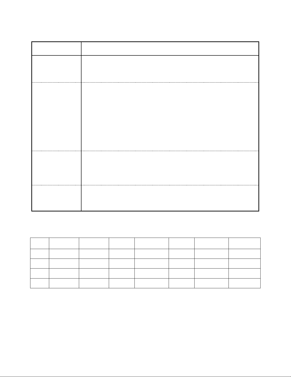
TROUBLESHOOTING
· Install the unit on a level solid surface.
· Reduce humidity where the unit is installed.
12 oz. Can
Capacity
Problem Remedy
· Check the power cord and make sure it is plugged in and has power.
Compressor will
not start
Poor performance
Unit noisy
· Check the temperature controller. If it is in the “OFF” position, turn it clockwise to
set a desired temperature.
· Move the unit from direct sunlight.
· Move the unit away from heating devices.
· Install the unit in a well ventilated place, with at least 2 inches of clearance on all
sides.
· Clean the condenser if heavy dust is collected.
· Clear contents from blocking the inside air duct.
· Check the temperature controller for correct setting.
· Check the covers and be sure they are completely closed.
· Maintain 2 inches of clearance from the wall.
· Check for loose parts or mounting.
· Keep the tubing free from any contact to avoid rattle.
Condensation on
cabinet exterior
and/or floor
· Check the drain line to make sure it is not disconnected inside the cabinet and it
drains into the drain pan in the compressor area.
SPECIFICATIONS
Model # Dividers Electrical Amps NEMA Plug HP
BC50 3 115/60/1 3.5 5-15P 3/8 857 R290
BC65 4 115/60/1 3.5 5-15P 3/8 1191 R290
BC80 5 115/60/1 3.5 5-15P 3/8 1575 R290
BC95 6 115/60/1 3.5 5-15P 3/8 1893 R290
Above specifications are subject to change without prior notice for quality improvement.
Refrigerant
3 4/19 Rev. M 143593
Page 4

BC SERIES PARTS LIST
ITEM NO.
PART NAME and DESCRIPTION
BC50
BC65
BC80
BC95
PART NO.
6
DOOR RAIL LEFT
X X X X 157656
DOOR RAIL FRONT
X 157658
DOOR RAIL FRONT
X 157659
DOOR RAIL FRONT
X 157660
DOOR RAIL FRONT
X 157661
8
DOOR RAIL BRACKET LEFT OR RIGHT
2 2 2 2 157662
9
AIR GUIDE BRACKET
2 2 2 2 157663
DOOR RAIL BRACKET FRONT
X 157665
DOOR RAIL BRACKET FRONT
X 157666
DOOR RAIL BRACKET FRONT
X 157667
DOOR RAIL BRACKET FRONT
X 157668
11
DOOR RAIL RIGHT
X X X X 157669
12
DUCT BRACKET
2 X X X 157670
DUCT GUIDE LEFT
X X X X 157671
DUCT GUIDE RIGHT
X X X X 157672
EVAP FAN MOTOR
2 2 3 3 145709
EVAP FAN BLADE
2 2 3 3 145710
EVAP COIL ASSY (R134a units)
X X 149824
EVAP COIL ASSY (R290 units)
X X 161790
EVAP COIL ASSY (R134a units)
X X 157678
EVAP COIL ASSY (R290 units)
X X 161799
DRAIN GUIDE
X X 157682
DRAIN GUIDE
X X 157683
17
EVAP DRAIN ELBOW A
X X X X 157684
18
EVAP DRAIN ELBOW B
X X X X 157685
UNIT COOLER DUCT 50
X 157687
UNIT COOLER DUCT 65
X 157688
UNIT COOLER DUCT 80 (R134a UNITS)
X 157689
UNIT COOLER DUCT 80 (R290 UNITS)
X 161800
UNIT COOLER DUCT 95 (R134a UNITS)
X 157690
UNIT COOLER DUCT 95 (R290 UNITS)
X 161801
EVAP FAN COVER
X X 157694
EVAP FAN COVER (R134A UNITS)
X X 157695
EVAP FAN COVER (R290 UNITS)
X X 161802
21
SHELF/DIVIDER BUSHINGS
42
57
90
102
157696
22
SHELF/DIVIDER SPRING
3 4 5 6 157697
23
SHELF/DIVIDER
3 4 5 6 157698
THERMOSTAT CONTROL ASSY (R134a UNITS)
X X X X 157703
THERMOSTAT CONTROL ASSY (R290 UNITS)
X X X X 161803
28
OPENER COVER ASSY
X X X X 159158
CAPILLARY TUBE (R134a UNITS)
X X X X 159160
HEAT EXCHANGER (CAP TUBE/SUCTION LINE) (R290 UNITS)
X X X X 161805
COMPRESSOR SK1A1C-L2W (R134a UNITS)
X X X X 150311
COMPRESSOR (R290 UNITS)
X X X X 161767
COMPRESSOR ELECTRONIC KIT (R134a UNITS)
X X X X 150312
COMPRESSOR ELECTRONIC KIT (R290 UNITS)
X X X X 161768
DRYER (R134a UNITS)
X X X X 159166
DRYER (R290 UNITS)
X X X X 161786
38
CONDENSER 50, 65, 80, 95
X X X X 159170
CONDENSER FAN MOTOR
X X X X 145751
CONDENSER FAN MOTOR BLADE
X X X X 145749
40
CABINET BASE
X X X X 159178
41
FRONT GRILL
X X X X 159180
47
EVA CENTER GUIDE
X X 2 2 159182
DOOR 50
2 159190
DOOR 65 & 95
2 3 159192
DOOR 80
3 159194
51
SIDE COVER
X X X X 159199
TOP BRACKET 1
2 2 159201
TOP BRACKET 2
2 2 159202
53
DOOR LOCK KEY
2 2 3 3 160743
56
FAN CONTROL PCB KIT
X X X X 161579
CASTERS (4) 2 LOCKING & 2 NON-LOCKING PLATE TYPE
X 160620
CASTERS (6) 3 LOCKING & 3 NON-LOCKING PLATE TYPE
X X X 160621
DOOR LOCK W/KEY
X X X X 161560
7
10
13
14
15
16
19
20
24
30
34
37
39
50
52
4 4/19 Rev. M 143593
Page 5

EXPLODED VIEW PARTS LIST – BC50 & BC65
5 4/19 Rev. M 143593
Page 6

EXPLODED VIEW PARTS LIST - BC80 & BC95
6 4/19 Rev. M 143593
Page 7

WIRING DIAGRAM
7 4/19 Rev. M 143593
 Loading...