

Page 1

IT - Generatore d’aria Calda
GB - Portable forced air heaters
DE - Tragbare hochdruck-heissluftturbinen
ES - Calentadores móviles de aire forzado
FR - Appareils de chauffage individuels à air forcé
NL - Mobiele ventilator-luchtverwarmer
PT - Aquecedores portáteis com ventilação forçada
DK - Flytbare luftcirkulations apparater
FI - Siirrettävä kuumailmapuhallin
NO - Flyttbar varmekanon
SV - Portabel varmluftsfl äkt
PL - Przenośne nagrzewnice powietrza pod ciśnieniem
RU - Тепловой генератор
CZ - Přenosná topná tělesa na dm chan vzduch
HU - Hordozható hőlégfúvók
Libretto uso e manutenzione - Operation and maintenance manual -
Bedienungsanweisung - Manual del proprietario - Manuel de L’utilisateur
- Gebruiksaanwijzing en onderhoud - Manual de instruções - Brugs- og vedli
geholdelsesvejledning - Käyttö-ja huoltokirja - Bruks- og vedlikeholdsmanual
- Bruksanvisning - Instrukcja obsługi i konserwacji - Руководство по
эксплуатации и уходу - Návod k použití a k údržbě - Használati utasítás
BV 70 E
.
Page 2
BV 70 E
2
SPECIFICATIONS - SPÉCIFICATIONS - TECHNISCHE DATEN - TECHNISCHE
GEGEVENS - DATI TECNICI - ASPECIFICACIONES - CARACTERÍSTICAS
TÉCNICAS - TEKNISKE KARAKTERISTIKKER - SPECIFIKATIONER
- SPECIFIKATIONER - TECHNICKÉ ÚDAJE - MŰSZAKI ADATOK -
SPESIFIKASJONER - SPECYFIKACJE - TEXHИЧECKИE XAPAKTEPИCTИKИ
BV 70 E
Potenza max - Max power - Max Wärmeleistung - Potencia max - Puissance ther. max. Max Vermogen - Värmestyrka max - Enimmäislämpöteho - Maks. Termisk Effekt - Maksimal
varmeeffekt - Wydajność - Hoминaльнaя выxoднaя мoщнocть - Teljesítmény - Jmenovitá
vákon
- Portata d’aria - Air output - Luftstrom - Heißluftausstoß - Salida de aire caliente - Débit
D’air - Blaasvermogen hete lucht - Hetluftsutsläpp - Kuumailmateho - Varmluftmængde i m3
i minuttet - Varmluftskapasitet - Wydajnosc cieplego powietrza - Bыxoд гopячeгo вoздyxa
- Meleg levegő kibocsátás - Vástup horkého vzduchu
Consumo di combustibile - Fuel Consumption - Kraftstoffverbrauch - Consumo
de combustible - Consommation Fuel - Brandstofverbruik - Bränsleförbrukning Polttoaineenkulutus - Petroleumsforbrug - Brennstofforbruk - Zuzycie paliwa - Pacxoд
топлива - Fűtőolaj fogyasztás - Spotreba paliva
Combustibile - Fuel - Kraftstoff - Combustible - Brandstof - Bränsle - Polttoaine - Brændstof
- Brennstoff - Paliwo - Toпливо - Fűtőolaj - Palivo
Capacità serbatoio - Fuel Tank Capacity - Kraftstofftank / Fassungsvermögen - Capacidad
del tanque de combustible - Capacité Du Reservoir Fuel - Tankinhoud - Tankstorlek Polttoainesäiliön tilavuus - Tankkapacitet i liter - Størrelse på brennstofftanken - Pojemność
zbiornika paliwa - Eмкость топливного бaкa - Fűtőolajtartály térfogata - Kapacita palivové
nádrže
Temperatura di gittata a 20 cm di distanza e 15°C temperatura ambiente
Alimentazione elettrica - Electric Requirements - Elektrischer Anschluß - Tension-V -
Requisitos eléctricos - Netvoeding - Elektrisk ström - Sähkövirta - El-type - Elektriske krav
- Wymagania odnosnie zasilania - Элeктpoпитaниe - Villamos csatlakozás - Potrebné
elektrické napetí
Potenza assorbita - Electric power absorbed - Aufgenommene E-Leistung - Potencia
eléctrica absorbida - Puissance électrique absorbée - Geabsorbeerd elektrisch vermogen
- Potência eléctrica absorvida - Absorberet elektrisk kraft - Ottoteho - Forbruk elektrisitet
- Upptagen elektrisk effekt - Pobór mocy spotřebovane elektřiny - Felvett teljesítmény
Forma di corrente
Peso - Weight - Gewicht - Peso - Poids - Gewicht - Varmeapparat vægt - Lämmittimen paino -
Vekt varmekanon - Vikt värmefl äkt - Cię ar nagrzewnicy - Вeс нагрeватeля - Hmotnost topného
tělesa - Hőlégfúvó súlya
Ø uscita fumi - Ø of fume outlet - Durchmesser Abgasrohr - Ø salida humos - Ø sortie fumée
- Ø rookafvoer - Ø da saída de gases - Røgudgang Ø - Savukaasun poistoputken halkaisija
- Ø røykutførsel - Ø skorstensutlopp - Średnica wylotu spalin - Диамeтр выходного
отвeрстия дыма - Průměr v pustě kouře - Füstgázelvezetés átmérő
Ugello - Nozzle - Düse - Boquilla - Buse - Straalpijp - Bico - Dyse - Polttoainesuutin - Kran Munstycke - Dysza - Форсунка - Tryska - Fúvóka
Prex pompa - Fuel pump pressure - Druck Brennstoffpumpe - Presión bomba combust.
- Pression pompe combust. - Druk brandstofpomp - pressão da bomba de combust. Brændstofpumpe tryk - Polttoainepumpun paine - Trykk i oljepumpen - tryck bränslepump
- Ciśnienie pompy paliwa - Давление насоса топлива - Tlak čerpadla paliva Üzemanyagszivattyú noyomás
Поглощаeмая элeктричeская мощность - V kon
17 kW
15.000 Kcal/h
550 m³/h
1,47 kg/h
diesel
40 Lt
98 °C
230 V / 50 Hz
300 W
AC
40 kg
120 mm
0,40 US gal/h 80°
9,5 bar
Page 3
GENERATORE D’ARIA CALDA
3
IT
INDICE
PRESENTAZIONE DEL PRODOTTO 3
INFORMAZIONE SULLA SICUREZZA 3
MESSA IN FUNZIONE 4
ARRESTO 4
DISPOSITIVI DI SICUREZZA 4
TRASPORTO E MOVIMENTAZIONE 4
PROGRAMMA DI MANUTENZIONE 4
PRINCIPIO DI FUMZIONAMENTO 5
QUADRO ELETTRICO 5
INDIVIDUAZIONE DEI GUASTI 5
RACCOMANDAZIONI
GENERALI
La serie B comprende generatori d’aria calda a riscaldamento
diretto che mescolano l’aria calda ceduta all’esterno ai fumi
della combustione. Per questo motivo il loro impiego è particolarmente indicato in ambienti aperti o con elevati ricambi d’aria,
dove si ha la necessità di riscaldare, scongelare o asciugare.
La serie BV invece comprende generatori d’aria calda a riscaldamento indiretto che, grazie ad uno scambiatore di calore,
permettono di separare i gas di combustione dall’aria calda
ceduta all’ambiente. In questo modo è possibile immettere una
corrente d’aria calda pulita all’interno del luogo da riscaldare e
convogliare all’esterno i fumi di scarico.
Le serie B e BV sono state progettate secondo i più moderni
criteri di sicurezza, funzionalità e durata: dispositivi di sicurezza
garantiscono sempre il corretto funzionamento della macchina,
l’impatto acustico è stato ridotto al minimo e l’accurata scelta dei
materiali garantisce un’elevata affi dabilità.
INFORMAZIONE SULLA
SICUREZZA
IMPORTANTE: leggere attentamente e completamente il
manuale d’istruzioni prima di assemblare e mettere in
funzione o la manutenzione di questo generatore. L’uso
del generatore può causare lesioni gravi o fatali a seguito
di ustioni, incendio, esplosione, scariche elettriche o
asfi ssia da ossido di carbonio.
fi
PERICOLO: L’asfi ssia da ossido di carbonio può
risultare fatale!
Asfi ssia da ossido di carbonio - I primi sintomi di asfi ssia da
ossidodi carbonio assomigliano a quelli dell’infl uenza, con cefa-
lee, capogiri e/o nausea. Tali sintomi potrebbero essere causati
dal funzionamento difettoso del generatore. Uscire immedia-
tamente all’aperto!Far riparare il generatore. Alcune persone
risentono maggiormente degli effetti dell’ossido di carbonio,
specie le donne gravide, coloro che soffrono di malattie cardiache o polmonari, gli anemici, gli ubriachi e quanti si trovano in
località ad alta quota.Accertarsi di leggere e comprendere tutte
le avvertenze. Conservare questo manuale a titolo di futuro riferimento: funge infatti da guida al funzionamento sicuro e corretto
del generatore.
● Usare solamente cherosene o gasolio per evitare i rischi di
incendio o di esplosione. Non fare mai uso di benzina,nafta,
solventi per vernici, alcool o altri combustibili altamentein-
fi ammabili.
● Rifornimento
a) Il personale incaricato del rifornimento deve essere qualifi -
cato ed avere totale dimestichezza con le istruzioni del fabbricante e con la normativa vigente in merito al rifornimento
sicuro dei generatori.
b) Usare solamente il tipo di combustibile espressamente
specifi cato sulla targhetta identifi cativa del generatore.
c) Prima di effettuare il rifornimento, spegnere completamente
la macchina, ed attendere che il generatore si raffreddi.
d) Nel corso del rifornimento, ispezionare tutte le linee del
combustibile ed i relativi raccordi, alla ricerca di eventuali
perdite. Qualsiasi perdita va riparata prima di rimettere in
funzione il generetore.
e) In nessuna circostanza si deve conservare nello stesso
edifi cio,in vicinanza del riscaldatore, una quantità di combus-
tibile superiore a quella necessaria per mantenere in funzione
il riscaldatore per una giornata. Le cisterne di magazzinaggio
del carburante devono trovarsi in una struttura separata.
f) Tutti i serbatoi del combustibile devono trovarsi ad una distanza minima da riscaldatori, cannelli ossidrici, attrezzature
per la saldatura e simili fonti di accensione (ad eccezione del
serbatoio del combustibile incorporato nel generatore) conforme alle normative vigenti.
g) Ogni qualvolta possibile, il combustibile va conservato in
locali il cui pavimento non permetta la penetrazione ed il gocciolio del combustibile stesso su fi amme sottostanti che pos-
sano causarne l’accensione.
h) La conservazione del combustibile va effettuata in conformità alla normativa vigente.
● Non usare mai il generatore in locali nei quali siano presenti
benzina, solventi per vernici o altri materiali altamente infi am-
mabili.
● Durante l’uso del riscaldatore, attenersi a tutte le ordinanzelo-
cali ed alla normativa vigente.
● I riscaldatori usati in prossimità di teloni, tende o altri ma-
terialidi copertura simili devono essere situati a distanza di
sicurezza conforme alla normativa vigente. Si consiglia anche
di usare materiali di copertura di tipo ignifugo. Tali materiali
vanno fi ssati in modo sicuro, onde evitare che prendano fuoco
e prevenire interferenze causate dal vento con il generatore.
● Usare solamente in ambienti privi di vapori infi ammabili o di
elevate concentrazioni di polvere.
● Alimentare il generatore solamente con corrente avente la
tensione e la frequenza specifi cate sulla targhetta identifi ca-
tiva.
● Usare solamente prolunghe a tre fi li opportunamente colle-
gate a massa.
● Porre il generatore caldo o in funzione su una superfi cie sta-
bile e livellata, in modo da evitare i rischi di incendio.
● Quando si sposta o si conserva il generatore, mantenerlo in-
posizione livellata, per evitare la fuoriuscita del combustibile.
● Tenere lontani i bambini e gli animali dal generatore.
● Scollegare il generatore dalla presa di rete quando non lo si
usa.
● Quando è controllato da un termostato, il riscaldatore può ac-
cendersi in qualsiasi momento.
● Non usare mai il generatore in stanze frequentemente abitate
né in camere da letto.
● Non bloccare mai la presa dell’aria (lato posteriore) né l’uscita
dell’aria (lato anteriore) del riscaldatore.
● Quando il riscaldatore è caldo, collegato alla rete o in funzione
non deve mai essere spostato, maneggiato, rifornito né soggetto ad alcun intervento di manutenzione.
Page 4
GENERATORE D’ARIA CALDA
4
IT
MESSA IN FUNZIONE
Prima di mettere in funzione il generatore e, quindi, prima di collegarlo alla rete elettrica di alimentazione si deve controllare che
le caratteristiche della rete elettrica di alimentazione corrispondano a quelle riportate sulla targhetta di identifi cazione.
AVVERTENZA: La linea elettrica di alimentazione del
generatore deve essere provvista di messa a terra e di
interruttore magneto-termico differenziale. La spina elettrica del generatore deve essere allacciata ad una presa
munita di interruttore di sezionamento.
Il generatore può funzionare in modo automatico solo quando
un dispositivo di controllo, quale, ad esempio, un termostato
o un orologio, sia collegato al generatore fi ssandone il cavo ai
morsetti 3 e 4 della spina 3 (Fig. 2) fornita con l’apparecchio (il
fi lo elettrico che collega i due morsetti deve essere rimosso ed
eventualmente rimontato solo quando si vuole che il generatore
funzioni senza il dispositivo di controllo). Per avviare la macchina si deve:
• se collegato, regolare il dispositivo di controllo in modo daconsentire il funzionamento (ad esempio, il termostato deve
essere selezionato sulla temperatura massima);
• disporre l’interruttore 1 (Fig.2) nella posizione con il simbolo:
ON il ventilatore si avvia e dopo alcuni secondi ha inizio la
combustione.
Alla prima messa in servizio o dopo lo svuotamento completo
del circuito del gasolio, il fl usso di gasolio all’ugello può essere
insuffi ciente e causare l’intervento dell’apparecchiatura di con-
trollo di fi amma che arresta il generatore; in questo caso, dopo
aver atteso per circa un minuto, premere il pulsante di riarmo 1
(Fig.2) e riavviare l’apparecchio. In caso di mancato funzionamento le prime operazioni da farsi sono le seguenti:
1. Controllare che il serbatoio contenga ancora del gasolio;
2. Premere il pulsante di riarmo 1 (Fig.2) ON;
3. Se dopo tali operazioni il generatore non funziona, si deve
consultare il paragrafo “INDIVIDUAZIONE DEI GUASTI” e
scoprire la causa del mancato funzionamento.
ARRESTO
Per arrestare il funzionamento dell’apparecchio si deve disporre
l’interruttore (1 Fig.2) nella posizione OFF o agire sul dispositivo di
controllo, ad esempio, regolando il termostato ad una temperatura
più bassa. La fi amma si spegne e il ventilatore continua a funziona-
re fi no al completo raffreddamento della camera di combustione.
TRASPORTO E
MOVIMENTAZIONE
AVVERTENZA Prima di spostare l’apparecchio si deve:
arrestare la macchina secondo le indicazioni del paragrafo precedente;disinserire l’alimentazione elettrica
estraendo la spina dalla presa elettrica ed attendere che il
generatore si raffreddi.
Prima di sollevare o spostare il generatore ci si deve assicurare che il tappo del serbatoio sia ben fi ssato. Il generatore può
essere fornito nella versione mobile, munito di ruote, o pensile,
montato su una struttutra di supporto con ancoraggi per il fi s-
saggio da eseguirsi mediante funi o catene. Nel primo caso per
il trasporto è suffi ciente afferrare il generatore per la maniglia di
sostegno e farlo scorrere sulle ruote. Nel secondo caso il sollevamento deve essere fatto utilizzando un carrello elevatore o
attrezzatura simile.
PROGRAMMA DI
MANUTENZIONE PREVENTIVA
Per il regolare funzionamento dell’apparecchio è necessario
pulire periodicamente la camera di combustione, il bruciatore
e il ventilatore.
AVVERTENZA Prima di iniziare qualsiasi operazione di
manutenzione si deve: arrestare la macchina secondo
le indicazioni del paragrafo precedente; disinserire
l’alimentazione elettrica estraendo la spina dalla presa
elettrica ed attendere che il generatore si raffreddi.
Ogni 50 ore di funzionamento si deve:
• Smontare la cartuccia del fi ltro, estrarla e pulirla con gasolio
pulito;
• Smontare la carenatura esterna cilindrica e pulire la parte interna e le pale del ventilatore;
• Controllare lo stato dei cavi e degli innesti in alta tensione sugli
elettrodi;
• Smontare il bruciatore pulendone le parti, pulire gli elettrodi e
regolarne la distanza al valore indicato a pag.61 nello schema
regolazione elettrodi.
DISPOSITIVI DI SICUREZZA
Il generatore è dotato di un’apparecchiatura elettronica per il
controllo della fi amma. Se si verifi cano una o più anomalie di
funzionamento tale apparecchiatura provoca l’arresto della
macchina e l’accensione della spia del pulsante di riarmo (1
Fig.2). Un termostato di sovratemperatura interviene e provoca
l’interruzione dell’alimentazione di gasolio se il generatore si
surriscalda: il termostato si riarma automaticamente quando
la temperatura della camera di combustione diminuisce sino a
raggiungere il valore massimo ammesso. Prima di rimettere in
funzione il generatore si deve individuare ed eliminare la causa
che ha prodotto il surriscaldamento (ad esempio, ostruzione
della bocca di aspirazione e/o di mandata dell’aria, arresto del
ventilatore). Per riavviare la macchina si deve premere il pulsante di riarmo e ripetere le istruzioni specifi che del paragrafo
“MESSA IN FUNZIONE”.
Page 5
GENERATORE D’ARIA CALDA
PRINCIPIO E SCHEMA DI FUNZIONAMENTO
3
1
11
2
64
5
87 9
10
5
IT
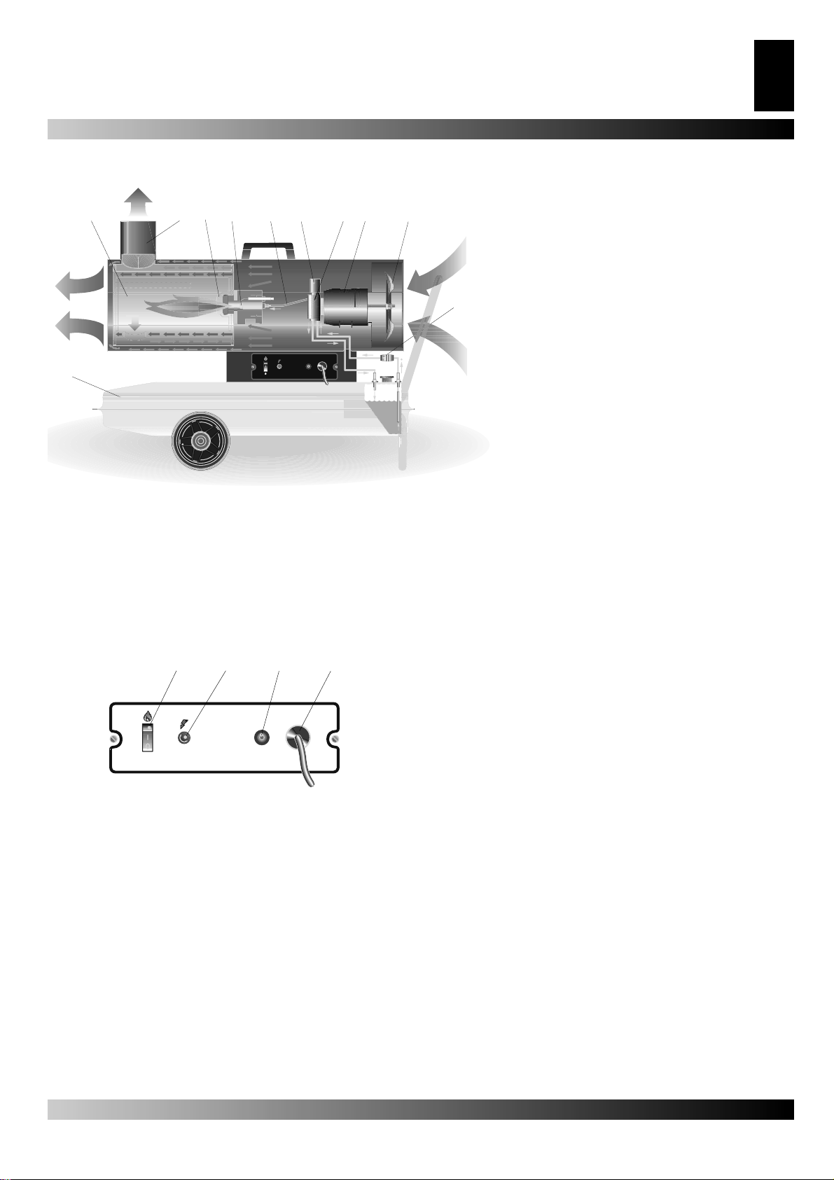
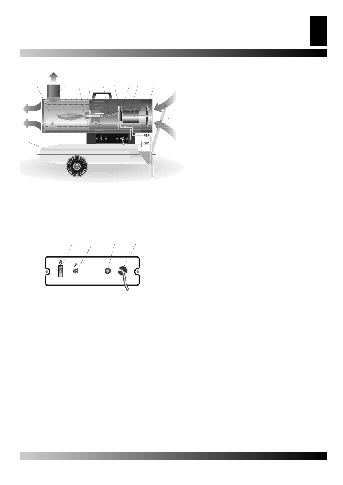
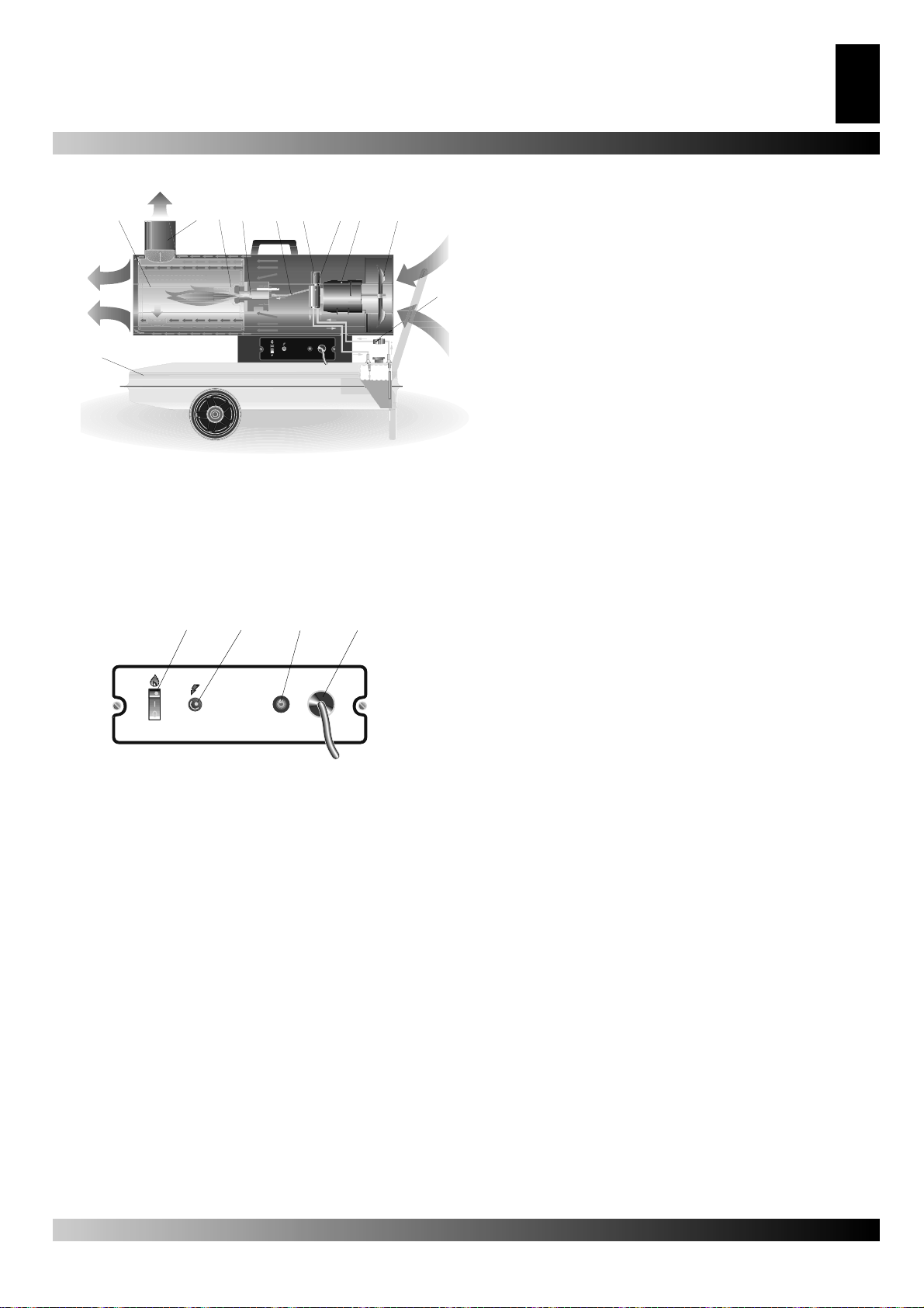
Figura 4 - Sezione dello schema di funzionamento.
1. Camera di combustione, 2. Raccordo fumario anti vento, 3.
Bruciatore, 4. Ugello, 5. Circuito combustibile, 6. Elettrovalvola
combustibile, 7. Pompa, 8. Motore, 9. Ventola, 10. Filtro combustibile, 11. Serbatoio.
QUADRO ELETTRICO
1
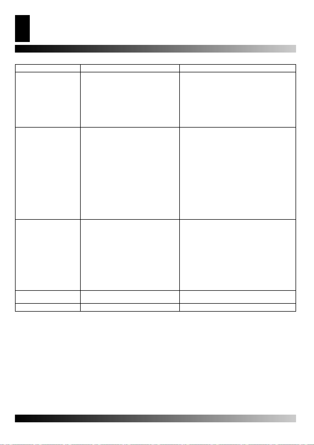
Figura 6 - Quadro elettrico.
1. Pulsante di RESET, 2. Presa per termostato ambiente, 3.
Interruttore principale, 4. Cavo di alimentazione, 5. Spia tensione.
2
3
4
Page 6

GENERATORE D’ARIA CALDA
6
IT
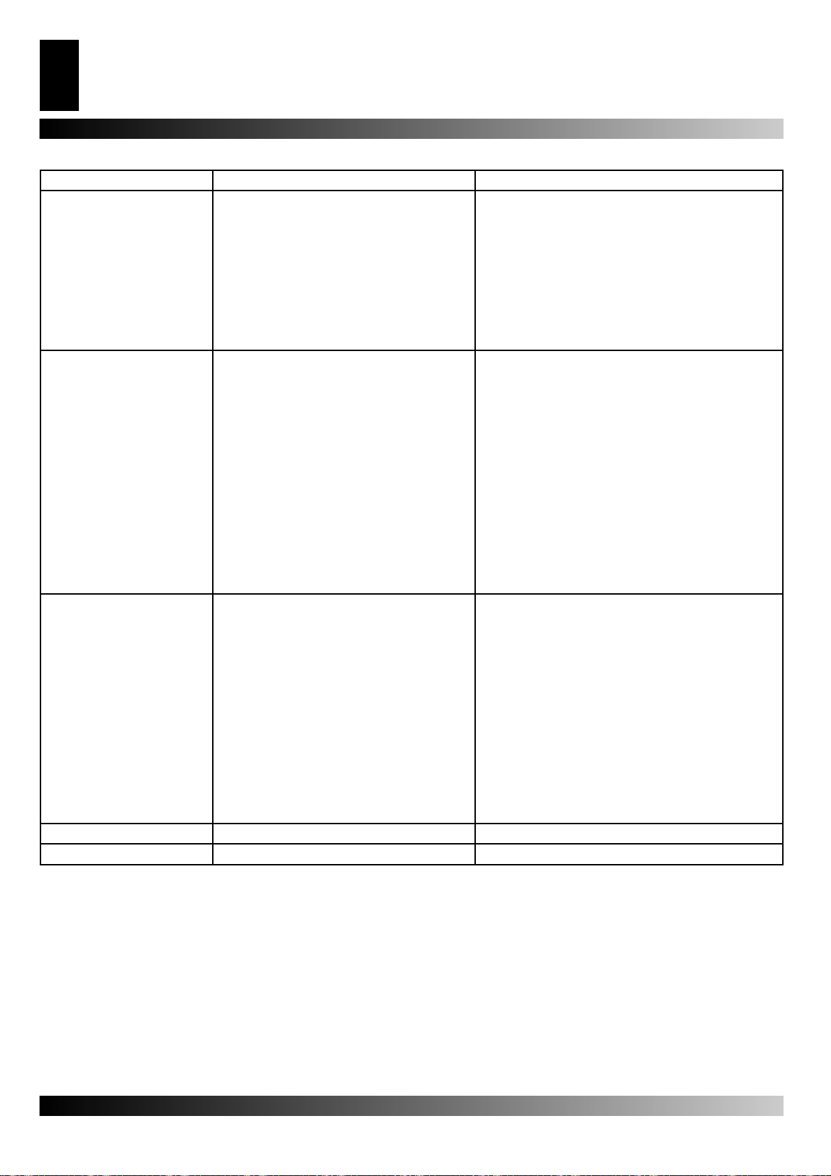
INDIVIDUAZIONE DEI GUASTI
Guasto Causa Rimedio
Il ventilatore non si avvia e la
fi amma non si accende
Il ventilatore si avvia e la
fi amma non si accende o
non rimane accesa
Il ventilatore si avvia e
la fi amma si accende
producendo fumo
Il generatore non si arresta 1.Tenuta elettrovalvola difettosa 1.Sostituire il corpo elettrovalvola
Il ventilatore non si arresta 1.Termostato del ventilatore difettoso 2.Sostituire il termostato FA
1. Alimentazione elettrica mancante
2. Regolazione errata dell’eventuale dispositivo
di controllo
3. Dispositivo di controllo difettoso
4. Avvolgimento del motore bruciato o interrotto
1. Accensione non funzionante
2. Apparecchiatura di controllo fi amma difettosa
3. Fotocellula non funzionante
4. Non arriva gasolio al bruciatore o arriva
inquantità insuffi ciente
5. Elettrovalvola non funzionante
1. Aria di combustione insuffi ciente
2. Aria di combustione eccessiva
3. Gasolio utilizzato sporco o contente acqua
4. Infi ltrazioni di aria nel circuito del gasolio
5. Quantità insuffi ciente di gasolio al brucia-
tore
6. Quantità eccessiva di gasolio al bruciatore
1a Verifi care le caratteristiche dell’impianto elettrico
(230 V - 1~ - 50 Hz)
1b Controllare la funzionalità e il posizionamento
dell’interruttore
1c Controllare l’integrità dei fusibili
2 Controllare che la regolazione del dispositivo di con-
trollo sia corretta (ad es., la temperatura selezionata
sul termostato deve essere superiore alla tempera-
tura dell’ambiente)
3 Sostituire il dispositivo di controllo
4 Sostituire il motore
1a Controllare i collegamenti dei cavi di accensione
agli elettrodi e al trasformatore
1b Controllare la posizione degli elettrodi e la loro
distanza secondo lo schema
1c Controllare che gli elettrodi siano puliti
1d Sostituire il trasformatore d’accensione
2. Sostituire l’apparecchiatura
3. Pulire la fotocellula o sostituirla
4a Controllare l’integrità del giunto pompa-motore
4b Controllare che non ci siano infi ltrazioni di aria nel
circuito del gasolio verifi cando la tenuta dei tubi e
della guarnizione del fi ltro
4c Pulire o, se necessario, cambiare l’ugello
5a Controllare il collegamento elettrico ed il termost. LI
5b Pulire ed eventualmente sostituire l’elettrovalvola
1a Rimuovere tutti i possibili ostacoli od ostruzioni ai
condotti di aspirazione e/o di mandata dell’aria
1b Verfi fi care la posizione dell’anello di regolazione
dell’aria
1c Pulire il disco bruciatore
2 Verfi fi care la posizione dell’anello di regolazione
dell’aria
3a Sostituire il gasolio usato con gasolio pulito
3b Pulire il fi ltro gasolio
4 Verifi care la tenuta dei tubi e della guarnizione del
fi ltro gasolio
5a Verifi care il valore della pressione della pompa
5b Pulire o sostituire l’ugello
6a Verifi care il valore della pressione della pompa
6b Sostituire l’ugello
Page 7

HOT AIR GENERATOR
7
GB
CONTENTS
IDENTIFICATION OF PART “B” AND “BV” 7
SAFETY INFORMATION 7
STARTING THE HEATER 7
TURNING OFF THE HEATER 8
SAFETY DEVICES 8
MOVING AND TRANSPORTING THE HEATER 8
PREVENTATIVE MAINTENANCE PROGRAMME 8
HEATER FUNCTIONING DIAGRAM 9
ELECTRIC CONTROL PANEL 9
TROUBLESHOOTING 10
IDENTIFICATION OF PART “B”
AND “BV”
Series B is a line of hot air generators with direct heating system
that mix the heat released externally with combustion residues.
These heaters are particularly suitable to be used for heating,
defrosting and drying both outdoors and in areas with frequent
air exchanges.
Series BV is a line of hot air generators with indirect heating
system. These generators have a heat exchanger that enables
to separate exhaust combustion gases from the heat released in
the environment, so that it is possible to inject a fl ow of clean hot
air in the area that needs to be heated and to discharge exhaust
fumes externally.
Series B and BV hot air generators are designed in compliance
with current safety, performance and life standards, are fi tted
with safety devices confi gured to guarantee continuous
operation, minimize noise and are manufactured in carefully
selected materials that ensure maximum reliability.
SAFETY INFORMATION
WARNING
IMPORTANT: Read the manual carefully before attempting to assemble,switch on or service this heater. The use
of the heater may cause serious or fatal injuries resulting
from burns, fi re, explosion, electrical discharge or carbon
monoxide poisoning.
DANGER:Carbon monoxide poisoning can be fatal!
Carbon monoxide poisoning The fi rst symptoms of carbon
monoxide poisoning are similar to those of fl u, with headache,
dizziness and/or nausea.These symptoms may be caused by
the defective functioning of the heater. Go outside into the open
air immediately! Have the heater repaired. Some people feel
the effects of carbon monoxide to a greater extent, especially
pregnant women, those suffering from anaemia, cardiac or lung
conditions, those who are drunk and anyone at a high altitude.
Ensure that you have read and understood all the warnings.
Keep this manual for future reference – it is a guide to the safe
and correct functioning of the heater.
• Use only fuel oil no.1 in order to avoid the risk of fi re or explo-
sion. Never use petrol, naphtha, paint solvents, alcohol or other
highly infl ammable combustibles.
• Fuelling
a) The individual responsible for fuelling the heater must have
the relevant competence and be completely familiar with the
manufacturer’s instructions and with current norms concer-
ning the safe fuelling of the heaters.
b) Only use the type of fuel expressly specifi ed on the identifi ca-
tion label of the heater.
c) Before adding fuel, extinguish all fl ames, including the pilot
light, and wait until the heater has cooled down.
d) While adding fuel, inspect all the fuel lines and joins to make
sure there are no leaks.
Any leak whatsoever must be repaired before switching on
the heater.
e) In no circumstances must more than one day’s supply of
fuel be stored in the same building in proximity to the heater.
Fuel storage tanks must be kept in a separate location.
f) All fuel tanks must be kept at a minimum distance from hea-
ters, oxyacetylene torches, welding equipment etc. (with the
exception of the fuel tank incorporated into the heater) following regulations.
g) Wherever possible, fuel should be stored in a place where
the fl oor does not allow fuel to seep through and drip onto live
fl ames beneath, which might cause fi re.
h) Fuel must be stored in compliance with current norms.
• Never use the heater anywhere where petrol, paint solvents or
other highly infl ammable vapours are present.
• While using the heater, follow all local ordinances and current
norms.
• Heaters used in the proximity of tarpaulins, curtains or other covering materials must be situated at a safe distance following regulations.
It is also recommended to use fi reproof materials.
These materials should be fi xed safely so as to ensure that
they do not catch fi re and are not blown by the wind.
• Only use in locations where there are no infl ammable fumes or
high concentrations of dust.
• Power the heater only with electric power that has the voltage,
frequency and number of phases specifi ed on the identifi cation
label.
• Only use earthed three-wire extension cords.
• In order to avoid the risk of fi re, make sure the heater is on a
fi rm, fl at surface when it is being used or is hot.
• When moving or storing the heater, keep it level to avoid fuel
loss.
• Keep children and animals away from the heater.
• Disconnect the heater from the mains supply when not in use.
• When controlled by a thermostat, the heater may come on at
any moment.
• Never use the heater in frequently used rooms or in bedrooms.
• Never obstruct the air intake (rear end) or the air output (front
end) of the heater.
• When the heater is hot, connected to the mains supply or in
use, it must never be moved, handled, fi lled up with fuel or
serviced in any way.
STARTING THE HEATER
Before turning on the heater and therefore before attaching it
to the mains power supply, check that the characteristics of the
mains power supply are the same as those indicated on the
identifi cation label.
Page 8

8
GB
HOT AIR GENERATOR
WARNING:The electric power cable of the heater must
be earthed and must have a differential magnetothermal
switch.The electric plug must be connected to a socket
which has a disconnecting switch.
The heater can only work automatically when a control mechanism, for example a thermostat or clock, is connected to it by attaching the cable to terminals 3 and 4 of plug 3 (Fig.2) supplied
with the product (the electric wire that links the two terminals
must be removed and remounted only if the heater is to be used
without the control mechanism).
To turn on the machine, do the following:
• If the control mechanism is connected, adjust it so that the
machine can function (for example, the thermostat must be set
to the maximum temperature).
• Flip switch 1 (Fig. 2) to the position with the symbol: ON – the
fan comes on and after several seconds the heater starts burning.
The fi rst time the heater is used, or after the fuel circuit has been
completely drained, the fl ow of fuel oil to the nozzle may be in-
suffi cient and may activate the fl ame cut out mechanism, which
will turn off the heater;if this happens, wait for about a minute
and then press the reset button 1 (Fig. 2) to start the machine
again.
The fi rst steps to take if the machine does not work are the
following:
1. Check that there is fuel in the tank.
2. Press the reset button 1 (Fig.2) ON.
3. If the heater still does not work, consult the
“TROUBLESHOOTING”guide.
Before lifting or moving the heater, make sure that the fuel tank
cap is fi rmly in place.
The heater may be supplied in a portable version, with wheels,
or a suspended version, mounted on a support structure and
fi xed in place with wires or chains. In the former case, to move
the heater, simply grasp the support handle and wheel the heater. In the latter case, the heater must be lifted with a fork-lift
truck or a similar piece of equipment.
PREVENTATIVE MAINTENANCE PROGRAMME
To ensure that the heater continues to work properly, it is necessary to periodically clean the combustion chamber, the burner
and the fan.
WARNING The following steps must be carried out before servicing the heater: turn the heater off, following the
instructions in the previous section; disconnect the plug
from the power supply and wait for the heater to cool.
Every 50 hours of use it is necessary to:
• Dismantle the fi lter cartridge, remove it and clean it with clean
fuel oil.
• Remove the exterior cylindrical casing and clean the inside
and the blades of the fan.
• Check the condition of the cables
tions on the electrodes.
• Dismantle the burner, clean the parts, then clean the electrodes and regulate them to the distance indicated on page 61 in
the electrode regulation diagram.
and the high voltage connec-
TURNING OFF THE HEATER
To turn off the machine, move switch 1 (Fig. 2) to the “0” position
or adjust the control mechanism, for example turning the thermostat to a lower position. The fl ame will go off and the fan will
continue to function until the combustion chamber has cooled
down completely.
SAFETY DEVICES
The heater is equipped with an electronic device to control the
fl ame.If there is an anomaly in the functioning, the machine will
be turned off and the reset button light 1 (Fig.2) will come on.
An over-heating thermostat cuts in and shuts off the fuel supply
if the heater overheats:the thermostat resets itself automatically
when the temperature in the combustion chamber diminishes
and reaches the maximum permitted value.
Before turning the heater on again, the cause of the overheating
must be identifi ed and removed (for example, a blockage in the
suction orifi ce and/or of the air fl ow duct, the non-functioning
of the fan). To turn on the machine again, press the reset button and repeat the specifi c instructions outlined in the section
“STARTING THE HEATER”.
MOVING AND TRANSPORTING
THE HEATER
WARNING The following steps must be carried out before moving the heater: turn the heater off, following the
instructions in the previous section; disconnect the plug
from the power supply and wait for the heater to cool.
Page 9
HEATER FUNCTIONING DIAGRAM
3
1
11
2
64
5
87 9
10
HOT AIR GENERATOR
9
GB
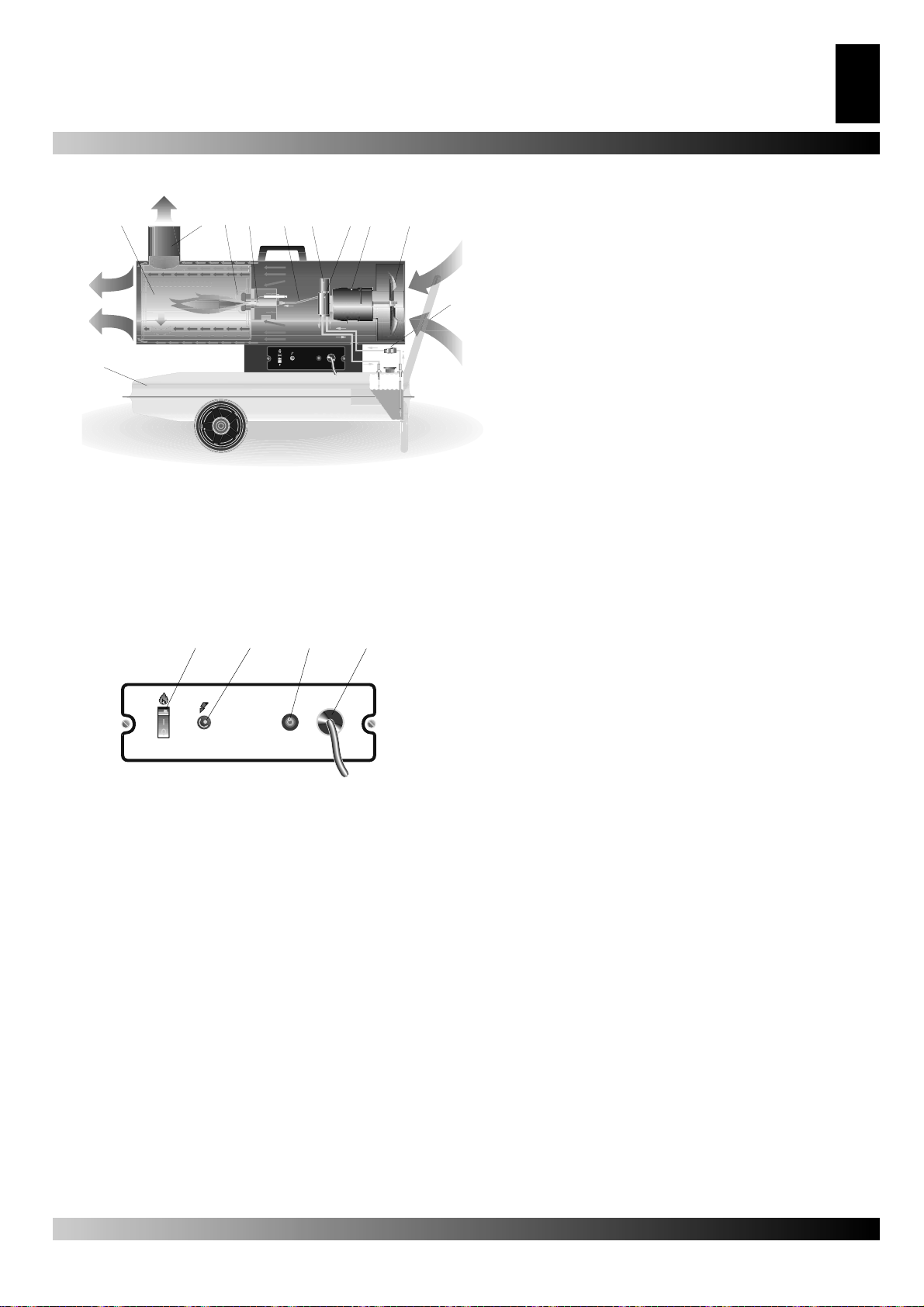
Figur 1 - Heater functioning diagram.
1. Combustion chamber, 2. Anti-wind fl ue connection, 3. Burner, 4. Noz-
zle, 5. Fuel circuit, 6. Electric fuel valve, 7. Fuel pump, 8. Motor, 9. Fan,
10. Filter, 11. Fuel tank.
ELECTRIC CONTROL PANEL
1
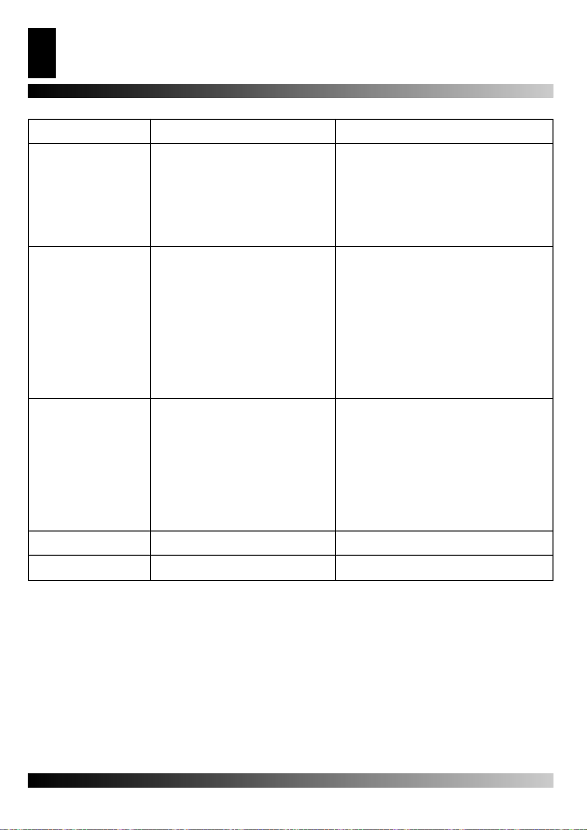
Figur 2 - Electric control panel.
1. Main cable, 2. Power indicator, 3. Socket for ambient thermo-
stat, 4. Power cable.
2
3
4
Page 10
HOT AIR GENERATOR
10
GB
TROUBLESHOOTING
Observed fault Possible cause Solution
The fan does not come on
and the fl ame does not light
The fan comes on but the
fl ame does not light or does
not remain lit
The fan comes on and the
fl ame lights, but produces
smoke
The heater does not switch
off
The fan does not switch off 1.Faulty fan thermostat 2.Replace the FA thermostat
1. No electric current
2. Incorrect setting on the control mechanism
(if fi tted)
3. Faulty control mechanism
4. Motor winding burnt out or broken
1. Ignitor is not functioning
2. Faulty fl ame cut out mechanism
3. Non-functioning photoelectric cell
4. Fuel is not reaching the burner or a suffi -
cient a mount is not arriving
5. Electric valve is not functioning
1 Insuffi cient air for combustion
2 Too much air for combustion
3 Fuel is dirty or contains water
4 Air has fi ltered into the fuel circuit
5 Inadequate quantity of fuel in burner
6 Too much fuel in burner
1.Defective electric valve seal 1.Replace the electric valve part
1a Check the characteristics of the electrical system
(230V - 1~ - 50 Hz)
1b Check that the switch works and is in the correct
position
1c Check that the fuse has not blown
2 Check that the control mechanism setting is correct
(e.g.the temperature setting on the thermostat must
be higher than the ambient temperature)
3 Replace the control mechanism
4 Replace the motor
1a Check the connections of the ignition cables to the
electrodes and transformer
1b Check the position of the electrodes and the
distance between them, in accordance with the
diagram
1c Check that the electrodes are clean
1d Replace the ignition transformer
2 Replace the mechanism
3 Clean or replace the photoelectric cell
4a Check that the connection between the pump and
the motor is intact
4b Check that air has not fi ltered into the fuel circuit,
checking the tubes and the fi lter seal
4c Clean or, if necessary, replace the nozzle
5a Check the electrical connection
5b Check the LI thermostat
5c Clean or, if necessary, replace the electricvalve
1a Remove anything blocking or obstructing theaspi-
ration and/or airfl ow ducts
1b Check the position of the air regulation ring
1c Clean the burner disc
2 Check the position of the air regulation ring
3a Replace the fuel with clean fuel
3b Clean the fuel fi lter
4 Check the condition of the tubes and the sealof the
fuel fi lter
5a Check the pump pressure
5b Clean or replace the nozzle
6a Check the pump pressure
6b Replace the nozzle
Page 11

TRAGBARE HOCHDRUCK-HEISSLUFTTURBINEN
11
DE
INHALT
BESCHREIBUNG DER GERÄTETEILE 11
SICHERHEITSHINWEISE 11
INBETRIEBNAHME 12
AUSSCHALTEN 12
SICHERHEITSVORRICHTUNGEN 12
TRANSPORT UNDBEWEGUNG 12
PRÄVENTIVES WARTUNGSPROGRAMM 12
BETRIEBSSCHEMA 13
SCHALTTAFEL 13
STÖRUNGEN UND DEREN BEHEBUNG 14
BESCHREIBUNG DER GERÄTETEILE
Die Serie B umfasst Warmluftgeneratoren mit direkter Heizwirkung, die die nach außen abgegebene Wärme mit den Verbrennungsrückständen mischen. Aus diesem Grund sind
sie besonders für offene Räume oder Räume mit ständigem
Luftaustausch geeignet, in denen man heizen, auftauen oder
trocknen will.
Die Serie BV hingegen umfasst Warmluftgeneratoren mit indirekter Heizwirkung, bei denen dank eines Wärmeaustauschers
die nach der Verbrennung verbliebenen Gase von der nach
außen abgegebenen Wärme getrennt werden. Dadurch ist es
möglich, saubere Warmluft in den zu erwärmenden Raum zu
blasen und die Abgase nach außen zu leiten.
Die Serien B und BV richten sich, was Sicherheit, Funktionalität
und Dauer betrifft, nach neuesten Kriterien: Sicherheitsvorrichtungen garantieren die korrekte Funktion des Geräts, die
Betriebsgeräusche wurden auf ein Minimum reduziert und die
sorgfältige Auswahl der Materialien machen es äußerst zuverlässig.
SICHERHEITSHINWEISE
WARNUNGEN
WICHTIG:Lesen Sie die Betriebsanleitung aufmerksam
und ganz durch,bevor Sie mit Montage, Inbetriebnahme
oder Wartung des Geräts beginnen. Der unsachgemäße
Gebrauch des Heißluftgenerators kann zu schweren Verletzungen und zum Tod durch Verbren-nungen,Hausbra
nd,Explosion,elektrische Schläge oder Vergiftung durch
Kohlenmonoxid führen.
GEFAHR: Die Vergiftung durch Kohlenmonoxid kann zum
Tod führen!
Vergiftung durch Kohlenmonoxid Die ersten Symptome einer
Kohlenmonoxidvergiftung ähneln jenen einer Erkältung, mit
Kopfschmerzen, Schwindelgefühlen und/oder Übelkeit.Diese
Symptome könnten auf ein fehlerhaftes Funktionieren des
Heißluftgenerators zurückzuführen sein. Gehen Sie sofort
ins Freie! Lassen Sie das Gerät reparieren. Einige Menschen
reagieren besonders empfi ndlich auf die Wirkung des Kohlen-
monoxids, insbesondere schwangere Frauen, Menschen mit
Herz- oder Lungenkrankheiten, Anämiekranke, Angetrunkene,
generell alle Menschen in höheren Lagen.
Seien Sie sicher, alle Sicherheitshinweise gelesen und verstanden zu haben. Bewahren Sie diese Betriebsanleitung auf, um
darin nachschlagen zu können;sie dient Ihnen als Hilfe beim sicheren und sachgemäßen Umgang mit dem Heißluftgenerator.
• Verwenden Sie ausschließlich Leichtöl Nr.1, um jede Brandoder Explosionsgefahr zu vermeiden.Verwenden Sie niemals
Benzin, Diesel, Lösungsmittel für Lacke, Alkohol oder andere
leicht entfl ammbare Brennstoffe.
• Befüllung
a) Das mit der Befüllung betraute Personal muss qualifi ziert und absolut mit den Anweisungen des Her-
stellers und den geltenden Vorschriften für die sichere Befüllung von Heißluftgeneratoren vertraut sein.
b) Verwenden Sie ausschließlich den Brennstoff, der ausdrücklich auf dem Typenschild des Heißluftgenerators angegeben ist.
c) Bevor Sie das Gerät befüllen, löschen Sie
alle Flammen, einsch ließlich der Pilotfl amme,
und warten Sie, bis der Generator abgekühlt ist.
d) Kontrollieren Sie während der Befüllung alle Brennstoffl eitungen und die entsprechenden Verbindun-
gen, um einen eventuellen Ölverlust festzustellen.
Jedes Leck muss repariert werden, bevor der Heißluftgenerator wieder in Betrieb genommen wird.
e) Unter keinen Umständen darf im selben Gebäude,
also in der Nähe des Heißluftgenerators, eine größere
Menge Brennstoff gelagert werden, als notwendig ist,
um das Gerät einen Tag lang zu betreiben. Das Brennstoffl ager muss sich in einem anderen Gebäude befi nden.
f) Alle Brennstofftanks müssen sich in einem Mindestabstand
von 7 m von Heizgeräten, Knallgasbrennern, Schweißgeräten und ähnlichen Zündquellen befi nden (mit Ausnah-
me des in den Generator integrierten Brennstofftanks).
g) Wann immer möglich muss der Brennstoff in Räumen
aufbe wahrt werden, deren Boden kein Eindringen und
Durchsickern des Brennstoffes auf darunterliegende Flammen erlaubt, die dessen Entzündung verursachen würden.
h) Die Aufbewahrung des Brennstoffes muss unter Einhaltung
der geltenden Vorschriften erfolgen.
• Der Heißluftgenerator darf nie in Räumen benutzt werden, in
denen sich Benzin, Lösungsmittel für Lacke oder andere leicht
entfl ammbare Dämpfe befi nden.
• Bei der Benutzung des Heißluftgenerators müssen alle lokalen
Bestimmungen und geltenden Vorschriften beachtet werden.
• Heißluftgeneratoren, die in der Nähe von Planen, Vorhängen oder ähnlichen Abdeckungen verwendet werden sollen,
müssen in geeignetem Sicherheitsabstand dazu aufgestellt
werden.Der empfohlene Mindestsicherheitsabstand beträgt
304,8 cm. Wir empfehlen auch,feuerhemmende Abdeckmaterialien zur verwenden. Diese Materialien müssen sicher befestigt sein, um zu verhindern, dass sie Feuer fangen und etwa
durch den Wind mit dem Gerät in Berührung kommen.
• Verwenden Sie das Gerät nur in Räumen, in denen sich keine
entfl ammbaren Dämpfe oder hohe Staubkonzentration befi n-
den.
• Schließen Sie das Gerät nur an die Stromversorgung an, wenn
deren Spannung, Frequenz und Phasenanzahl den auf dem
Typenschild angegebenen Werten entsprechen.
• Verwenden Sie ausschließlich dreiadrige Verlängerungskabel,
die entsprechend geerdet sind.
• Stellen Sie den warmen oder laufenden Heißluftgenerator
auf eine stabile und ebene Oberfl äche, um Brandgefahr zu
vermeiden.
• Auch wenn das Gerät bewegt oder aufbewahrt wird, muss es
immer gerade stehen, um ein Austreten des Brennstoffes zu
verhindern.
• Halten Sie Kinder und Tiere fern.
• Nehmen Sie das Gerät vom Stromnetz, wenn Sie es nicht
benutzen.
• Denken Sie daran, dass sich das Gerät jederzeit einschalten
kann, wenn es über einen Thermostat gesteuert wird.
Page 12

12
DE
TRAGBARE HOCHDRUCK-HEISSLUFTTURBINEN
• Verwenden Sie den Heißluftgenerator nie in häufi g genutzten
oder gar Schlafräumen.
• Verdecken Sie niemals die Luftansaugung (Rückseite) oder
den Luftauslass (Vorderseite) des Heißluftgenerators.
• Wenn der Heißluftgenerator warm, an das Stromnetz angeschlossen oder in Betrieb ist, darf er weder verstellt, bewegt,
befüllt noch auf irgendeine Art gewartet werden.
INBETRIEBNAHME
Bevor Sie den Heißluftgenerator in Betrieb nehmen und ihn
an die Stomversorgung anschließen, überprüfen Sie, ob die
Eigenschaften der Stomversorgung den auf dem Typenschild
angegebenen Werten entsprechen.
WARNUNG: Der Stromkreis, an den der Heißluftgenerator
angeschlossen wird,muss geerdet und mit einem thermomagnetischen Schutzschalter versehen sein. Der Stecker
des Geräts muss an eine Steckdose mit Trennschalter
angeschlossen werden.
Der Heißluftgenerator kann nur automatisch funktionieren,
wenn ein Steuergerät, etwa ein Thermostat oder eine Zeitschaltuhr, an das Gerät angeschlossen ist;dessen Kabel muss an die
Klemmen 3 und 4 des mit dem Gerät gelieferten Steckers (Abb.
2) angeschlossen werden (die Brücke, die die beiden Klemmen
verbindet, muss entfernt und nur, wenn das Gerät wieder ohne
Steuergerät funktionieren soll, wieder angebracht werden).
Um die Maschine in Betrieb zu nehmen, muss:
• wenn ein solches angeschlossen ist, das Steuergerät so geregelt sein, dass es einen Betrieb zulässt (der Thermostat z.B.
muss auf Maximaltemperatur eingestellt sein);
• der Schalter 1 (Abb.2) in die Stellung mit dem Symbol ON gebrachtwerden: der Ventilator läuft an und nach einigen Sekunden setzt die Verbrennung ein.
Bei der ersten Inbetriebnahme oder nach einer kompletten Entleerung der Ölleitung kann der Öldruck an der Düse zu niedrig
sein und einen Eingriff der Flammenüberwachung hervorrufen,
die den Generator anhält;in diesem Fall warten Sie etwa eine
Minute und drücken dann die Reset-Taste 1 (Abb.2), um das
Gerät neu zu starten. Wenn das Gerät nicht funktioniert, unternehmen Sie folgende Schritte:
1. Überprüfen Sie, dass der Tank noch Brennstoff enthält;
2. drücken Sie die Reset-Taste 1 (Abb. 2);
3. wenn der Generator nach diesen Maßnahmen nicht funktio-
niert, schlagen Sie unter “STÖRUNGEN UND DEREN BEHEBUNG” nach und suchen Sie dort nach der Ursache dafür.
Luftauslass oder Stillstand des Ventilators).Um das Gerät neu
zu starten, und befolgen Sie die Anweisungen des Abschnitts
“INBETRIEBNAHME”.
TRANSPORT UNDBEWEGUNG
WARNUNG Bevor das Gerät bewegt wird:schalten Sie
das Gerät nach den Anweisungen des vorhergehenden
Abschnitts aus; unterbrechen Sie die Stromversorgung,
indem Sie den Stecker ziehen und lassen Sie den Heißluftgenerator abkühlen.
Bevor das Gerät angehoben oder bewegt wird, versichern Sie
sich, dass der Deckel des Tanks sicher verschlossen ist.
Der Heißluftgenerator ist als transportables Gerät mit Rollen
lieferbar oder in einer Hängeversion, die auf eine Stützkonstruktion mit Verankerungen für die Befestigung mit Ketten oder
Seilenmontiert ist. Im ersten Fall kann das Gerät einfach am
Handgriff genommen und gerollt werden. Im zweiten Fall ist es
notwendig, einen Gabelstapler oder ein ähnliches Gerät einzusetzen, um es zu bewegen.
PRÄVENTIVES WARTUNGSPROGRAMM
Für einen einwandfreien Betrieb des Heißluftgenerators ist es
notwendig, regelmäßig die Brennkammer, den Brenner und den
Ventilator zu reinigen.
WARNUNG Vor dem Beginn jeglicher Wartung:
schalten Sie das Gerät nach den Anweisungen des
vorhergehenden Abschnitts aus; unterbrechen Sie die
Stromversorgung,indem Sie den Stecker ziehen und lassen Sie den Heißluftgenerator abkühlen.
Nach jeweils 50 Betriebsstunden ist es notwendig:
• die Filterkartusche abzumontieren, zu entnehmen und mit sauberem Öl zu reinigen;
• die Außenverkleidung abzunehmen, das Innere des Geräts
und die Ventilatorfl ügel zu reinigen;
• den Zustand der Kabel und der Hochspannungsverbindungen
der Elektroden zu überprüfen;
• den Brenner abzumontieren und dessen Teile zu reinigen, die
Elektroden zu reinigen und deren Abstand auf die auf S.61
angegebenen Werte einzustellen.
AUSSCHALTEN
Um das Gerät auszuschalten, muss der Schalter 1 (Abb. 2) auf
“0” gestellt werden oder auf das Steuergerät eingewirkt werden,
zum Beispiel, indem Sie den Thermostat auf eine niedrigere
Temperatur einstellen.Die Flamme geht aus, der Ventilator läuft
weiter, bis die Brennkammer vollständig abgekühlt ist.
SICHERHEITSVORRICHTUNGEN
Der Generator verfügt über eine elektronische Flammenüberwachung. Wenn eine oder mehrere Betriebsstörungen auftreten,
bewirkt diese den Stillstand des Geräts und die Beleuchtung der
Reset-Taste 1 (Abb. 2).
Wenn der Generator überhitzt ist, greift ein Überhitzungsthermostat ein und bewirkt die Unterbrechung der Brennstoffversorgung; der Thermostat stellt sich selbst zurück, wenn die
Termperatur der Brennkammer auf den erlaubten Maximalwert
gefallen ist.Bevor der Generator wieder in Betrieb genommen
wird, muss die Ursache für die Überhitzung gefunden und
beseitigt werden (z.B.Verstopfung von Luftansaugung oder
Page 13
TRAGBARE HOCHDRUCK-HEISSLUFTTURBINEN
ARBEITSWEISE
3
1
11
Abbildung 1 - Betriebsschema B.
1. Brennkammer, 2. Kamin-Anschlussrohr mit Windschutz, 3. Brenner, 4.
Düse, 5. Brennstoffl eitung, 6. Elektrisches Brennstoffventil, 7. Ölpumpe, 8.
Motor, 9. Ventilator, 10. Filter, 11. Brennstofftank.
2
64
5
87 9
10
13
DE
SCHALTTAFEL
1
Abbildung 2 - Schalttafel.
1. Hauptschalter, 2. Power indicator, 3. Steckvorrichtung für den
Raumthermostat, 4. Stromversorgungskabel.
2
3
4
Page 14
TRAGBARE HOCHDRUCK-HEISSLUFTTURBINEN
14
DE
STÖRUNGEN UND DEREN BEHEBUNG
BEOBACHTETE
STÖRUNG
Der Ventilator startet nicht
und die Flamme geht nicht
an
Der Ventilator startet und die
Flamme geht nicht an oder
bleibt nicht an
Der Ventilator startet und die
Flamme geht an,raucht aber
Der Generator bleibt nicht
stehen
Der Ventilator bleibt nicht
stehen
MÖGLICHE URSACHE BEHEBUNG
1 Keine Stromversorgung
2 Fehlerhafte Regelung des Steuergeräts
3 Steuergerät ist defekt
4 Motorwicklung ist durchgebrannt oder
durchtrennt
1 Zündung funktioniert nicht
2 Flammenüberwachung ist defekt
3 Fotozelle funktioniert nicht
4 Es gelangt kein oder nicht genügend Öl in
den Brenner
5 Elektroventil funktioniert nicht
1 Verbrennungsluft reicht nicht aus
2 Zu viel Verbrennungsluft
3 Verwendeter Brennstoff ist schmutzig oder
enthält Wasser
4 Luft in der Brennstoffl eitung
5 Ölmenge im Brenner reicht nicht aus
6 Zu viel Öl im Brenner
1 Dichtung des Elektroventils ist defekt 1 Gehäuse des Elektroventils ersetzen
1 Ventilatorthermostat ist defekt 1 FA-Thermostat ersetzen
1a Eigenschaften der Stromversorgung überprüfen
(230V - 1~ - 50 Hz)
1b Funktionieren und Stellung des Schalters über-
prüfen
1c Schmelzsicherung überprüfen
2 Regelung des Steuergeräts überprüfen (z.B.: ein-
gestellte Temp. muss höher als Raumtemp.sein)
3 Steuergerät ersetzen
4 Motor ersetzen
1a Verbindungen der Zündkabel zu den Elektroden
und zum Transformator überprüfen
1b Stellung der Elektroden und deren Abstand gemäß
Schema auf S.8 überprüfen
1c Sauberkeit der Elektroden überprüfen
1d Zündtransformator ersetzen
2 Gerät ersetzen
3 Fotozelle reinigen oder ersetzen
4a Kupplungsstück Pumpe-Motor überprüfen
4b Brennstoffl eitung auf Luft überprüfen, Schläuche
und Filterdichtung überprüfen
4c Düse reinigen und wenn nötig ersetzen
5a Stromanschluss überprüfen
5b LI-Thermostat überprüfen
5c Elektroventil reinigen und wenn nötig ersetzen
1a Alle möglichen Hindernisse und Verstopfungen an
Luftansaugung bzw. -auslass entfernen
1b Stellung des Luftzufuhr-Kontrollrings überprüfen
1c Stauscheibe reinigen
2 Stellung des Luftzufuhr-Kontrollrings überprüfen
3a Verwendetes Öl durch frisches Öl ersetzen
3b Ölfi lter reinigen
4 Dichte der Schläuche und der Ölfi lterdichtung über-
prüfen
5a Wert des Pumpendrucks überprüfen
5b Düse reinigen oder ersetzen
6a Wert des Pumpendrucks überprüfen
6b Düse ersetzen
Page 15
CALENTADORES MÓVILES DE AIRE FORZADO
15
ES
ÍNDICE
PRESENTACIÓN DEL PRODUCTO “B” y “BV” 15
INFORMACIONES SOBRE LA SEGURIDAD 15
PUESTA EN MARCHA 16
PARADA 16
DISPOSITIVOS DE SEGURIDAD 16
TRANSPORTE YDESPLAZAMIENTO 16
PROGRAMA DE MANTENIMIENTO
PREVENTIVO 16
TEORIA DE FUNCIONAMIENTO 17
CUADRO ELÉCTRICO 17
LOCALIZACIÓN DE AVERÍAS 18
PRESENTACIÓN DEL PRODUCTO
“B” y “BV”
La serie B comprende nuestros generadores de aire caliente
de combustión directa, que mezclan el aire caliente cedido al
local, con una pequeña cantidad de aire que proviene de la
combustión. Por este motivo su utilización está particularmente indicada en ambientes abiertos o con un elevado grado de
ventilación, donde exista la necesidad de calentar, descongelar
ó secar.
La serie BV comprende generadores de aire caliente de combustión indirecta que, gracias a un intercambiador de calor, permite separar los gases de la combustión del calor cedido al ambiente. De este modo, es posible aportar una corriente de aire
limpio al interior del lugar a calentar y expulsar al exterior los
humos de la combustión, a través de una sencilla chimenea.
La serie B y BV han sido proyectadas según los más modernos
criterios de seguridad, funcionalidad y duración: los dispositivos
de seguridad garantizan siempre el correcto funcionamiento
del equipo, el impacto acústico ha sido reducido al mínimo y
la cuidada selección de los materiales garantiza una elevada
calidad.
INFORMACIONES SOBRE LA
SEGURIDAD
INSTRUCCIONES
¡IMPORTANTE! lea atentamente y por completo el manual operativo antes de intentar el ensamblaje, lapuesta
en marcha o el mantenimiento de este calentador.El uso
del calentador puede causar lesiones graves o mortales
a consecuencia de quemaduras, incendio, explosión, descargas eléctricas o asfi xia por óxido de carbono.
¡CUIDADO! ¡La asfi xia por óxido de carbono puede resul-
tar mortal!
Asfi xia por óxido de carbono Los primeros síntomas de
asfi xia por óxido de carbono se parecen a los de la gripe, con
cefaleas, vahídos y /o náusea. Esos síntomas podrían ser causados por el funcionamiento defectuoso del calentador. ¡Salga
inmediatamenteal aire libre! Haga arreglar el calentador.
Algunas personas sufrenmayormente por los efectos del óxido
de carbono, sobre todo las mujeres embarazadas, los que padecen de enfermedades cardiacas o pulmonares, los anémicos,
los borrachos y todos los que se encuentran en localidades de
alta cota. Asegúrese de leer y comprender todas las instrucciones. Guarde este manual como punto de referencia para el
futuro: de hecho sirve de guía para el funcionamiento seguro y
correcto del calentador.
• Use sólo aceite combustible n.°1 para evitar riesgos de incendio
o de explosión. No use nunca gasolina, nafta, solventes para
barnices, alcohol u otros combustibles altamente infl amables.
• Abastecimiento
a) El personal encargado del abastecimiento debe ser
cualifi cado y tener absoluta familiaridad con las instruc-
ciones del fabricante y con la normativa vigente con respecto al abastecimiento seguro de los calentadores.
b) Use sólo el tipo de combustible expresamente especifi cado en la etiqueta que identifi ca el calentador.
c) Antes de proveer al abastecimiento apague todas las llamas, incluida la piloto, y espere que el calentador se enfríe.
d) Durante el abastecimiento, inspeccione todas las líneas del combustible y los enlaces correspondientes,
buscando eventuales pérdidas.Cualquier pérdida se
debe arreglar antes de poner en marcha el calentador.
e) En ningún caso se debe guardar en el mismo edifi -
cio, cerca del calentador, una cantidad de combustible
superior a la necesaria para mantener en función el
calentador durante un día.Los tanquesde almacenaje
del carburante deben estar en una estructura a parte.
f) Todos los tanques del combustible deben estar a una distancia mínima de calentadores, antorchas oxhídricas, equipos
soldadores y similares fuentes de encendido (a excepción
del tanque del combustible incorporado en el calentador).
g) Cada vez que sea posible, el combustible se deberá guardar en lugares cuyo suelo no permita la penetración y el goteo del combustible mismo sobre
llamas que estén abajo y que puedan encenderse.
h) El almacenamiento del combustible se debe efectuar conforme la normativa vigente.
• No use nunca el calentador en lugares donde haya gasolina, solventes para barnices u otros vapores altamente infl amables.
• Durante el uso del calentador, atenerse a todas las ordenanzas locales y a la normativa vigente.
• Los calentadores utilizados en las cercanías de tendales,
toldos u otros materiales de cobertura deben ser colocados
a distancia deseguridad de los mismos conforme la normativa
vigente.Se aconseja también deutilizar materiales de cobertura de tipo ignífugo. Esos materiales se deben fi jar de forma
segura, para evitar que prendan fuego y evitar que el viento
provoque interferencias con el calentador.
• Úselo sólo en lugares donde no haya vapores infl amables o
elevadas concentraciones de polvo.
• Alimente el calentador sólo con corriente cuya tensión, frecuencia y número de fases sean los especifi cados en la tarjeta
de identifi cación.
• Use sólo cables de prolongación de tres hilos oportunamente
conectados a masa.
• Ponga el calentador caliente o en función sobre una superfi cie
estable y nivelada, para evitar los riesgos de incendio.
• Cuando se desplaza o se conserva el calentador, hay que
mantenerlo en posición nivelada, para evitar la salida del
combustible.
• Haga de manera que los niños y los animales guarden distancia delcalentador.
• Desconectar el calentador del enchufe de red cuando no se usa.
• Cuando es controlado por un termostato, el calentador se puede encender en cualquier momento.
• No use nunca el calentador en piezas frecuentemente habitadas nien dormitorios.
• No bloque nunca la toma de aire (lado posterior) ni la salida del
Page 16
16
ES
CALENTADORES MÓVILES DE AIRE FORZADO
aire (lado anterior) del calentador.
• Cuando el calentador está caliente, conectado a la red o en
marcha no se debe nunca desplazar, manejar, abastecer ni
debe ser sometido a intervención de mantenimiento.
PUESTA EN MARCHA
Antes de poner en marcha el generador y, por tanto, antes de
enchufarla toma de corriente eléctrica de alimentación se debe
averiguar que las características de la red eléctrica de alimentación correspondan a las que están escritas en la etiqueta de
identifi cación.
¡CUIDADO!:La línea eléctrica de alimentación del generador debe estar dotada de toma a tierra y de interruptor
magneto-térmico diferencial. El enchufe del generador
debe estar enchufado a una toma dotada de interruptor
de seccionamiento.
El generador puede funcionar de manera automática sólo cuando un dispositivo de control, como por ejemplo, un termostato
o un reloj, esté conectado al generador fi jando el cable a los
bornes 3 y 4 del enchufe 3 (Fig.2) del que está dotado el aparato
(el cable eléctrico que conecta los dos bornes se debe quitar y
eventualmente remontar sólo cuando se quiere que el generador funcione sin el dispositivo de control). Para poner en marcha
la máquina se debe:
• si está conectada, regular el dispositivo de control de manera
que su funcionamiento sea posible (por ejemplo, el termostato
debe se debe poner a la temperatura máxima);
• colocar el interruptor 1 (Fig.2) en la posición con el símbolo: el
ventilador se pone en marcha y después de algunos segundo
sempieza la combustión.
La primera vez que se pone en marcha o después del vaciado
completo del circuito del gasóleo, el fl ujo de gasóleo a la boquil-
la puede ser insufi ciente y causar la intervención del aparato
de control de la llama que para el generador; en este caso,
después dehaber esperado alrededor de un minuto, apriete el
pulsador dereactivación 1 (Fig.2) y reencienda el aparato.
En caso de no funcionamiento las primeras operaciones que
hay que efectuar son las siguientes:
1.Controlar que el tanque aún contenga gasóleo;
2.Apretar el pulsador de reactivación 1 (Fig. 2) ON;
3.Si después de esas operaciones el generador no funciona,
se debe consultar el párrafo “LOCALIZACIÓN DE AVERÍAS” y
descubrir la causa del no funcionamiento.
PARADA
Para parar el funcionamiento del aparato se debe colocar el interruptor 1 (Fig.2) en la posición “0”o accionar el dispositivo de
control, por ejemplo, regulando el termostato a una temperatura
más baja. La llama se apaga y el ventilador sigue funcionando
hasta el completo refrigeración de la cámara de combustión.
del orifi cio de aspiración y/o de la presión del aire, parada del
ventilador). Para reponer en marcha la máquina se debe apretar
el pulsadorde reactivación 1 (Fig.2) y repetir las instrucciones
específi cas del párrafo “PUESTA EN MARCHA”.
TRANSPORTE
YDESPLAZAMIENTO
¡CUIDADO! Antes de desplazar el aparato se debe parar la
máquina según las instrucciones del párrafo anterior, desconectar la alimentación eléctrica sacando el enchufe de la
toma de corriente y esperar que el generador se enfríe.
Antes de levantar o desplazar el generador hay que asegurarse
que el tapón del tanque esté bien cerrado.
Se puede elegir el modelo móvil de generador, dotado de ruedas, o el modelo pénsil, montado sobre una estructura de soporte con anclaje para la fi jación que se debe efectuar mediante
cuerdas o cadenas. En el primer caso para el transporte es sufi ciente agarrar el generador por la manilla de soporte y hacerlo
por las ruedas. En el segundo caso el levantamiento se debe
hacer utilizando una carretilla elevadora o equipo parecido.
PROGRAMA DE
MANTENIMIENTO PREVENTIVO
Para el normal funcionamiento del aparato hace falta limpiar periódicamente la cámara de combustión, el quemador y el ventilador.
¡CUIDADO! Antes de empezar cualquier operación de
mantenimiento se debe parar la máquina según las instrucciones del párrafo anterior, desconectar la alimentación eléctrica sacando el enchufe de la toma de corriente
y esperar que el generador se enfríe.
Cada 50 horas de funcionamiento se debe:
• Desmontar el cartucho del fi ltro, sacarlo y limpiarlo con gasó-
leo limpio;
• Desmontar la carenadura externa cilíndrica y limpiar la parte
interna y las palas del ventilador;
trolar el estado de los cables y de los embragues en alta
• Con
tensión sobre los electrodos;
• Desmontar el quemador y limpiar sus partes, limpiar los
electrodos y regular la distancia con respecto al valor indicado
a la pag.61 en el esquema regulación electr
odos.
DISPOSITIVOS DE SEGURIDAD
El generador está dotado de un dispositivo electrónico para elcontrol de la llama. Si se verifi can una o más anomalías defun-
cionamiento ese dispositivo provoca la parada de la máquina y
el encendido de la luz indicadora del pulsador de reactivación 1
(Fig.2). Un termostato de sobretemperatura interviene y provoca la interrupción de la alimentación de gasóleo si el generador
se recalienta: el termostato se reactiva automáticamente cuando la temperatura de la cámara de combustión disminuye hasta
llegar el valor máximo admitido. Antes de volver a poner en
marcha el generador se debe localizar y eliminar la causa que
ha producido el sobrecalientamento (por ejemplo, obstrucción
Page 17
CALENTADORES MÓVILES DE AIRE FORZADO
TEORIA DE FUNCIONAMIENTO
3
1
11
Figura 1 - Modelos B version.
1. Cámera de combustión, 2. Racor del humo anti-viento, 3. Quemador,
4. Boquilla, 5. Electro-válvula combustible, 6. Circuito combustible, 7.
Ventilador, 8. Motor, 9. Bomba gasóleo, 10. Filter, 11. Tanque combustible.
2
64
5
87 9
10
17
ES
CUADRO ELÉCTRICO
1
Figura 2 - Cuadro eléctrico.
1. Hauptschalter, 2. Power indicator, 3. Steckvorrichtung für den
Raumthermostat, 4. Stromversorgungskabel.
2
3
4
Page 18
CALENTADORES MÓVILES DE AIRE FORZADO
18
ES
LOCALIZACIÓN DE AVERÍAS
AVERÍA OBSERVADA POSIBLE CAUSA SOLUCIÓN
El ventilador no se pone
en marcha y lallama no se
enciende
El ventilador se pone
en marcha y la llama no
se enciende o no queda
encendida
El ventilador se pone
en marcha y la llama se
enciende produciendo humo
El generador no se para 1 Electro-válvula no perfectamente estanca 1 Sustituya el cuerpo electro-válvula
El ventilador no se para 1 Termostato del ventilador defectuoso 1 Sustituya el termostato FA
1 Falta de alimentación eléctrica
2 Regulación incorrecta del eventual
dispositivo de control
3 Dispositivo de control defectuoso
4 Bobinado del motor quemado o cortado
1 Encendido que no funciona
2 Dispositivo de control de la llama defec-
tuoso
3 Fotocélula que no funciona
4 No llega gasóleo al quemador o llega en
cantidad insufi ciente
5 Electro-válvula que no funciona
1 Aire de combustión insufi ciente
2 Aire de combustión excesiva
3 Gasóleo empleado sucio o con agua
4 Infi ltraciones de aire en el circuito del gas-
óleo
5 Cantidad insufi ciente de gasóleo al que-
mador
6 Cantidad excesiva de gasóleo en el que-
mador
1a Verifi que las características de la instalación eléc-
trica (230V - 50 Hz)
1b Controle la funcionalidad y el posicionamiento del
interruptor
1c Controle la integridad del fusible
2 Controle que la regulación del dispositivo de control
sea correcta (por ej., la temperatura seleccionada
en el termostato debe ser superior a la temperatura
ambiente)
3 Sustituya el dispositivo de control
4 Sustituya el motor
1a Controle las conexiones de los cables deencen-
dido a los electrodos y al transformador
1b Controle la posición de los electrodos y sudistan-
cia según el esquema de Pág.8
1c Averigüe que los electrodos estén limpios
1d Sustituya el transformador de encendido
2 Sustituya el equipo
3 Limpie la fotocélula o sustitúyala
4aControle la integridad de la unión bomba -motor
4b Controle que no haya infi ltraciones de aire en el
circuito del gasóleo verifi cando que los tubos y la
junta del fi ltro sean perfectamente estancos
4c Limpie o, si necesario, cambie la boquilla
5a Controle la conexión eléctrica
5b Controle el termostato LI
5c Limpie y eventualmente sustituya la electro-
válvula
1a Elimine todos los posibles obstáculos u obstruc-
ciones a los tubos de aspiración y/o de impulsión
del aire
1b Controle la posición del anillo de regulación del
aire
1c Limpie el disco quemador
2 Controle la posición del anillo de regulación del
aire
3a Sustituya el gasóleo empleado con gasóleo limpio
3b Limpie el fi ltro gasóleo
4 Controle que los tubos y la junta del fi ltro gasóleo
sean perfectamente estancos
5a Controle el valor de la presión de la bomba
5b Limpie o sustituya la boquilla
6a Controle el valor de la presión de la bomba
6b Sustituya la boquilla
Page 19
APPAREILS DE CHAUFFAGE INDIVIDUELS À AIR FORCÉ
19
FR
TABLE DES MATIÈRES
PRÉSENTATION DES PRODUIT 19
INFORMATIONS SUR LA SÉCURITÉ 19
MISE EN SERVICE 20
ARRÊT 20
DISPOSITIFS DE SÉCURITÉ 20
TRANSPORT ET MANUTENTION 20
PROGRAMME DE MAINTEMANCE PRÉVENTIVE 20
PRINCIPES DE FONCTIONNEMENT 21
TABLEAU ÉLECTRIQUE 21
IDENTIFICATION DES PANNES 22
PRÉSENTATION DES PRODUIT
“B” ET “BV”
La série B comprend des générateurs d’air chaud à chauffage
direct qui mélangent l’air chaud rejeté à l’extérieur et les fumées
de combustion. Pour cette raison, ils sont particulièrement indiqués pour les espaces ouverts ou, en tous les cas, les pièces
avec une grande circulation d’air, où l’on doit chauffer, dégeler
ou sécher.
La série BV comprend, elle, des générateurs d’air chaud à
chauffage indirect qui, grâce à un échangeur de chaleur, permettent de séparer les gaz de combustion de l’air chaud rejeté à
l’extérieur. De la sorte, on peut introduire un courant d’air chaud
propre à l’intérieur de l’endroit que l’on souhaite chauffer, et canaliser à l’extérieur les fumées sales.
Les séries B et BV ont été conçues selon les meilleurs critères
de sûreté, de fonctionnement et de durée : des dispositifs de
sûreté garantissent le bon fonctionnement de la machine, le
bruit a été réduit au minimum et le choix scrupuleux des matériaux assure une très grande fi abilité.
INFORMATIONS SUR LA SÉCURITÉ
MISES EN GARDE
IMPORTANT :lire attentivement et dans son intégralité le
manuel opérationnel avant d’essayer d’effectuer l’assemblage, la mise en service ou la maintenance de cet appareil de chauffage. Son utilisation pourrait provoquer des
lésions graves, voire mortelles, suite à des brûlures, à un
incendie, à une explosion, à des décharges électriques
ou à une asphyxie par oxyde de carbone.
DANGER :l’asphyxie par oxyde de carbone peut être
mortelle!
Asphyxie par oxyde de carbone Les premiers symptômes
d’une asphyxie par oxyde de carbone ressemblent à ceux de
la grippe, avec l’apparition de maux de tête, vertiges et/ou nausées. Ces symptômes pourraient être causés par un fonctionnement défectueux de l’appareil de chauffage. Aller immédiatement dehors! Faire réparer l’appareil de chauffage.Certaines
personnes ressentent plus que d’autres les effets de l’oxyde de
carbone, notamment les femmes enceintes, les personnes atteintes de maladies cardiaques ou pulmonaires, les anémiques,
les personnes ivres et toutes celles qui se trouvent dans des
lieux situés en haute altitude.
Prendre soin de lire et de bien comprendre l’ensemble des mises en garde. Conserver ce manuel en vue d’une consultation
ultérieure :il fait, en effet, offi ce de guide au fonctionnement sûr
et correct de l’appareil de chauffage.
• Afi n d’éviter les risques d’incendie ou d’explosion, utiliser
exclusivement de l’huile combustible n°1. Ne jamais utiliser
d’essence, de naphte, de solvants pour peintures, d’alcool ou
d’autres combustibles hautement infl ammables.
• Ravitaillement
a) Le personnel préposé au ravitaillement doit être qualifi é et avoir une grande familiarité avec les instructions du
fabricant et avec la réglementation en vigueur relative au
ravitaillement en toute sécurité des appareils de chauffage.
b) Utiliser exclusivement le type de combustible expressément
spécifi é sur la plaquette d’identifi cation de l’appareil de chauffage.
c) Avant d’effectuer le ravitaillement, éteindre toutes les fl ammes, y compris la fl amme pilote, et at-
tendre que l’appareil de chauffage soit refroidi.
d) Au cours du ravitaillement, inspecter toutes les lignes
du combustible et les raccords correspondants, afi n de
vérifi er l’absence de fuites. Toute fuite doit être réparée
avant de remettre l’appareil de chauffage en service.
e) Ne conserver en aucun cas dans le même édifi ce, à proxi-
mité del’appareil de chauffage, une quantité de combustible
supérieure à celle nécessaire pour maintenir l’appareil de chauffage en service pendant une journée.Les citernes de stockage
du carburant doivent être situées dans une structure séparée.
f) Tous les réservoirs de combustible doivent se trouver à unedistance minimum des appareils de chauffage,
chalumeaux oxydriques, appareils de soudure et autres
sources d’allumage similaires (à l’exception du réservoir
de combustible incorporé dans l’appareil de chauffage).
g) Chaque fois que cela est possible, le combustible doit être
conservé dans des locaux dont le sol interdit toute pénétration
et tout égouttement continuel du combustible sur des fl ammes
sous-jacentes qui, de ce fait, pourraient en causer l’allumage.
h)La conservation du combustible doit être effectuée en conformitéavec les normes en vigueur.
• Ne jamais utiliser l’appareil de chauffage dans des locaux contenant de l’essence, des solvants pour peintures ou d’autres
vapeurs hautement infl ammables.
• Durant l’utilisation de l’appareil de chauffage, respecter toutes
les ordonnances locales et la réglementation en vigueur.
• Les appareils de chauffages employés à proximité de bâches,
rideaux ou autres matériaux de couverture du même genre
doivent être installés à une distance de sécurité.Il est également conseillé d’utiliser des matériaux de couverture de type
ignifuge. Ces matériaux doivent être fi xés de façon à ce qu’ils
ne puissent s’enfl ammer et éviter les interférences causées
par le vent avec l’appareil de chauffage.
• N’utiliser l’appareil que dans des locaux exempts de vapeurs
infl ammables ou de fortes concentrations de poussière.
• Alimenter l’appareil de chauffage exclusivement avec un courant dont la tension, la fréquence et le nombre de phases sont
spécifi és sur la plaquette d’identifi cation.
• Utiliser uniquement des rallonges à trois fi ls opportunément
raccordées à la masse.
• Installer l’appareil de chauffage chaud ou en service sur une
surface stable et bien nivelée, de manière à éviter les risques
d’incendie.
• En cas de déplacement ou de stockage de l’appareil de chauffage, faire en sorte que ce dernier maintienne une position
nivelée, pour éviter que du combustible s’en échappe.
• Ne pas laisser l’appareil de chauffage à la portée des enfants
et des animaux.
• En cas de non utilisation, débrancher l’appareil de chauffage
de la prise de réseau.
• Lorsqu’il est contrôlé par un thermostat, l’appareil de chauffage
peut se mettre en marche à tout moment.
• Ne jamais utiliser l’appareil de chauffage dans des pièces fréquemment occupées ainsi que dans des chambres à coucher.
• Ne jamais obstruer la prise d’air (face arrière) et la sortie d’air
Page 20

20
FR
APPAREILS DE CHAUFFAGE INDIVIDUELS À AIR FORCÉ
(face avant) de l’appareil de chauffage.
• Lorsqu’il est chaud, branché au réseau ou en service, l’appareil de chauffage ne doit jamais être déplacé, manié, ravitaillé
ou faire l’objet d’interventions de maintenance.
MISE EN SERVICE
Avant de mettre le générateur en service et, par conséquent,
avant de le raccorder au réseau d’alimentation électrique, il
est nécessaire de contrôler que les caractéristiques du réseau
d’alimentation électrique correspondent à celles indiquées sur la
plaquette d’identifi cation.
! MISE EN GARDE :la ligne d’alimentation électrique du
générateur doit être pourvue d’une mise à la terre et d’un
interrupteur magnétothermique différentiel.
La fi che électrique du générateur doit être branchée à une
prise pourvue d’un interrupteur de sectionnement.
Le générateur ne peut fonctionner en mode automatique que si
le dispositif de contrôle tel que, par exemple, un thermostat ou
une horloge, est raccordé au générateur en en fi xant le câble
aux bornes 3 et 4 de la fi che 3 (Fig.2) fournie avec l’appareil
(le fi l électrique qui relie les deux bornes ne doit être ôté et,
éventuellement, remonté, que si l’on souhaite que le générateur
fonctionne sans dispositif de contrôle).
Pour mettre la machine en marche, il faut :
• s’il est raccordé, régler le dispositif de contrôle de façon à autoriser le fonctionnement (par exemple, le thermostat doit être
programmé sur la température maximum) ;
• mettre l’interrupteur 1 (Fig.2) dans la position rapportant le
symbole :ON le ventilateur se met en marche et, après quel-
ques secondes, la combustion commence.
Lors de la première mise en service ou après la vidange complète du circuit du gasoil, le fl ux de gasoil en direction de la
buse peut s’avérer insuffi sant et causer l’intervention de l’ap-
pareillage de contrôle de fl amme qui arrête le générateur ;dans
ce cas, après avoir attendu environ une minute, appuyer sur le
bouton-poussoir de réarmement 1 (Fig.2) et remettre l’appareil
en marche.
En cas de non-fonctionnement, les premières opérations qu’il
convient d’effectuer sont les suivantes :
1. Contrôler que le réservoir contient encore du gasoil ;
2. Appuyer sur le bouton-poussoir de réarmement 1 (Fig.2) ;
3. Si, après ces opérations, le générateur ne fonctionne toujours
pas, consulter le paragraphe “IDENTIFICATION DES PANNES”
et trouver la cause de ce non-fonctionnement.
ARRÊT
Pour arrêter l’appareil, il est nécessaire de mettre l’interrupteur 3
(Fig.6) sur “0” ou d’intervenir sur le dispositif de contrôle, par exemple, enréglant le thermostat sur une température plus basse.La
fl amme s’éteint et le ventilateur continue de fonctionner jusqu’à ce
que la chambre de combustion soit entièrement refroidie.
surchauffe (par exemple, une obstruction de la bouche d’aspiration et/ou de refoulement de l’air, un arrêt du ventilateur).Pour
remettre la machine en marche, appuyer sur le bouton-poussoir
de réarmement 1 (Fig.2) et répéter les instructions spécifi ques
rapportées au paragraphe “MISE EN SERVICE”.
TRANSPORT ET MANUTENTION
MISE EN GARDE Avant de déplacer l’appareil, il est nécessaire : de mettre la machine hors tension en suivant
les indications fournies au paragraphe précédent ;de
débrancher l’alimentation électrique en retirant la fi che
de la prise électrique, et d’attendre que le générateur soit
refroidi.
Avant de soulever ou de déplacer le générateur, il est nécessaire de
vérifi er si le bouchon du réservoir est bien fi xé.Le générateur peut
être fourni dans la version mobile, pourvu de roues ou pendante,
monté sur une structure de support avec des ancrages servant à la
fi xation au moyen de cordes ou de chaînes.Pour le transport, dans
le premier cas, il suffi t de prendre le générateur par la poignée et
de le faire rouler. Dans le second cas, le levage doit être effectué à
l’aide d’un chariot élévateur ou d’un appareil du même type.
PROGRAMME DE MAINTENANCE
PRÉVENTIVE
Pour que l’appareil fonctionne correctement, il est nécessaire de
nettoyer périodiquement la chambre de combustion, le brûleur
et le ventilateur.
MISE EN GARDE Avant d’entamer une quelconque opération d’entretien, il est nécessaire de mettre la machine
hors tension en suivant les indications rapportées au paragraphe précédent; de débrancher l’alimentation électrique en retirant la fi che de la prise électrique,et d’attendre
que le générateur soit refroidi.
Toutes les 50 heures de fonctionnement, il est nécessaire :
• de démonter la cartouche du fi ltre, de l’extraire et de la net-
toyer avec du gasoil propre ;
• de démonter le carénage cylindrique externe et de nettoyer la
partie intérieure ainsi que les pales du ventilateur;
• de contrôler l’état des câbles et des branchements à haute
tension sur les électrodes;
• de démonter le brûleur et de nettoyer les pièces qui le composent, de nettoyer les électrodes et d’en régler la distance selon
la valeur indiquée à la page 61 dans le schéma de réglage des
électrodes.
DISPOSITIFS DE SÉCURITÉ
Le générateur est équipé d’un appareillage électronique de
contrôle de la fl amme. En cas de présence d’une ou plusieurs
anomalies de fonctionnement, cet appareillage provoque l’arrêt
de la machine et l’allumage du témoin du bouton-poussoir de
réarmement 1 (Fig. 2).
Un thermostat de surtempérature intervient et provoque la coupure de l’alimentation en gasoil si le générateur se surchauffe :le
thermostat se réarme automatiquement lorsque la température
de la chambre de combustion diminue et atteint la valeur maximum admise. Avant deremettre le générateur en service, il est
nécessaire d’identifi er et d’éliminer la cause qui a provoqué la
Page 21

APPAREILS DE CHAUFFAGE INDIVIDUELS À AIR FORCÉ
PRINCIPES DE FONCTIONNEMENT
3
1
11
Figure 1 - Modèles BV.
1. Chambre de combustion, 2. Raccord de cheminée anti-vent, 3. Brûleur, 4.
Buse, 5. Circuit combustible, 6. Électrovanne combustible, 7. Pompe gasoil,
8. Moteur, 9. Ventilateur, 10. Filter, 11. Réservoir combustible.
2
64
5
87 9
10
21
FR
TABLEAU ÉLECTRIQUE
1
Figure 2
2
3
4
1. Interrupteur principal, 2. Témoin de tension, 3. Prise pour
thermostat ambiant, 4. Cordon d’alimentation.
Page 22

APPAREILS DE CHAUFFAGE INDIVIDUELS À AIR FORCÉ
22
FR
IDENTIFICATION DES PANNES
PANNE CAUSE POSSIBLE SOLUTION
Le ventilateur ne se met pas
en marche et la fl amme ne
s’allume pas
Le ventilateur se met en
marche et la fl amme ne
s’allume pas ou ne reste pas
allumée
Le ventilateur se met en
marche et lafl amme s’allume
en produisant de lafumée
Le générateur ne s’arrête pas 1 Joint d’étanchéité de l’électrovanne dé-
Le ventilateur ne s’arrête pas 1 Thermostat du ventilateur défectueux 1 Remplacer le thermostat FA
1 Alimentation électrique absente
2 Réglage erroné de l’éventuel dispositif
decontrôle
3 Dispositif de contrôle défectueux
4 Enroulement du moteur brûlé ou interrompu
1 L’allumage ne fonctionne pas
2 Appareillage de contrôle de fl amme défec-
tueux
3 La photocellule ne fonctionne pas
4 Le gasoil n’arrive pas au brûleur ou y arrive
en quantité insuffi sante
5 L’électrovanne ne fonctionne pas
1 Air de combustion insuffi sant
2 Air de combustion excessif
3 Le gasoil utilisé est sale ou contient de l’eau
4 Infi ltrations d’air dans le circuit du gasoil
5 Le brûleur reçoit une quantité insuffi sante
de gasoil
6 Le brûleur reçoit une quantité excessive de
gasoil
fectueux
1a Vérifi er les caractéristiques de l’installation élec-
trique (230V - 1~ - 50 Hz)
1b Contrôler la fonctionnalité et le positionnement de
l’interrupteur
1c Contrôler l’état du fusible
2 Contrôler que le réglage du dispositif de contrôle
est correct (par ex., la température sélectionnée sur
le thermostat doit être supérieure à celle du milieu
ambiant)
3 Remplacer le dispositif de contrôle
4 Remplacer le moteur
1a Contrôler les branchements des câbles d’allumage
sur les électrodes et le transformateur
1b Contrôler la position des électrodes et leur dis-
tance selon le schéma rapporté à la page 8
1c Contrôler que les électrodes sont propres
1d Remplacer le transformateur d’allumage
2 Remplacer l’appareillage
3 Nettoyer la photocellule ou la remplacer
4a Contrôler l’état du joint pompe-moteur
4b Contrôler qu’il n’y a pas d’infi ltrations d’air dans le
circuit du gasoil en vérifi ant l’étanchéité des tuyaux
et du joint du fi ltre
4c Nettoyer ou, si nécessaire, changer la buse
5a Contrôler le branchement électrique
5b Contrôler le thermostat LI
5c Nettoyer et, éventuellement, remplacer
l’électrovanne
1a Enlever tous les possibles obstacles ou obstruc-
tions présents dans les conduits d’aspiration et/ou
de refoulement de l’air
1b Vérifi er la position de l’anneau de réglage de l’air
1c Nettoyer le disque du brûleur
2 Vérifi er la position de l’anneau de réglage de l’air
3a Sustituya el gasóleo empleado con gasóleo limpio
3b Nettoyer le fi ltre à gasoil
4
Vérifi er l’étanchéité des tuyaux et du joint du fi ltre
à gasoil
5a Vérifi er la valeur de la pression de la pompe
5b Nettoyer ou remplacer la buse
6a Vérifi er la valeur de la pression de la pompe
6b Remplacer la buse
1 Remplacer le corps de l’électrovanne
Page 23

MOBIELE VENTILATOR-LUCHTVERWARMER
23
NL
INDEX
PRESENTATIE VAN PRODUCT 23
VEILIGHEIDSINFORMATIE 23
INGEBRUIKNAME 24
UITSCHAKELING 24
VEILIGHEIDSVOORZIENINGEN 24
TRANSPORT EN VERPLAATSING 24
PREVENTIEF ONDERHOUD-SPROGRAMMA 24
OVERZICHT VAN DE WERKING 25
ELEKTRISCH CIRCUIT 25
IDENTIFICATIE VAN PROBLEMEN 26
PRESENTATIE VAN PRODUCT
“B” EN “BV”
De B-serie omvat warmeluchtgeneratoren met directe verwarming die de aan de omgeving afgegeven warmte met de verbrandingsresten mengt. Dit maakt deze generatoren bijzonder
geschikt voor gebruik in open omgevingen en omgevingen waar
met hoge luchtcirculatie, waar verwarming, ontdooiing of droging nodig is.
De BV-serie omvat daarentegen warmeluchtgeneratoren met
indirecte verwarming die dankzij een warmtewisselaar de verbrandingsgasresten kunnen scheiden van de warmte die aan
de omgeving wordt afgegeven. Zo gaat er een schonere warmeluchtstroom naar de te verwarmen omgeving en worden de
rookgassen afgevoerd.
De B- en BV-serie zijn ontwikkeld op basis van de meest actuele criteria op het gebied van veiligheid, functionaliteit en duurzaamheid: veiligheidsvoorzieningen zorgen ervoor dat het apparaat altijd correct functioneert, het geluidsniveau is minimaal
en een zorgvuldige materiaalselectie staat garant voor optimale
betrouwbaarheid.
VEILIGHEIDSINFORMATIE
WAARSCHUWINGEN
! BELANGRIJK:lees de hele bedieningshandleiding zorgvuldig voordat u begint met de montage,ingebruikname
of onderhoud van deze verwarmer. Het gebruik van de
verwarmer kan ernstig of dodelijk letsel veroorzaken
ten gevolge van verbranding, vuur, explosie, elektrische
schokken of koolmonoxidevergiftiging.
! GEVAAR:koolmonoxidevergiftiging kan dodelijk zijn!
Koolmonoxidevergiftiging De eerste symptomen van kool-
monoxidevergiftiging lijken op die van griep:hoofdpijn, duizeligheid en/of misselijkheid. Dergelijke symptomen kunnen worden
veroorzaakt door een gebrekkige werking van de verwarmer.
Begeef u onmiddellijk in debuitenlucht! Laat de verwarmer
gerepareerd worden. Bepaalde personen hebben extra te lijden
van de effecten van koolmonoxidever-giftiging:zwangere vrouwen, hart- en longpatiënten, personen met bloedarmoede, personen onder invloed van alcohol en bewoners van hooggelegen
gebieden. Zorg ervoor dat u alle waarschuwingen gelezen en
begrepen hebt.
Bewaar deze handleiding om deze in de toekomst opnieuw te
kunnenraadplegen:deze dient als gids voor een veilig en correct
gebruik vande verwarmer.
• Gebruik uitsluitend eersteklas brandolie om brand- en explosiegevaar te vermijden. Gebruik nooit benzine, stookolie,
verfoplosmiddelen, alcohol of andere makkelijk ontvlambare
brandstoffen.
• Bijvullen
a) Het personeel belast met het bijvullen dient gekwalifi ceerd te zijn en volledig vertrouwd te zijn met de
instructies van de fabrikant en de geldende normen
met betrekking tot het veilig bijvullen van verwarmers.
b) Gebruik uitsluitend het type brandstof dat specifi ek
is vermeld op het identifi catieplaatje van de verwarmer.
c) Doof voor het bijvullen eerst alle vlammen, inclusief
de waakvlam, en wacht tot de verwarmer is afgekoeld.
d) Inspecteer tijdens het bijvullen alle brandstofl ei-
dingen en fi ttingen op eventuele lekken. Eventu-
ele lekken dienen te worden gerepareerd voordat
de verwarmer opnieuw in gebruik wordt genomen.
e) In geen enkel geval mag men in de buurt van de verwarmer
in hetzelfde gebouw meer brandstof opslaan dan nodig is om
de verwarmer een dag te laten werken. De brandstofreservoirs
moeten zich in een afzonderlijke accommodatie bevinden.
f) Alle brandstoftanks moeten zich minimaal op een afstand van verwarmers, lasbranders, soldeerapparatuur
en soortgelijke ontstekingsbronnen (met uitzondering
van de brandstoftank die in de verwarmer is ingebouwd).
g) De brandstof dient zo mogelijk te worden opgeslagen in
ruimten met vloerbedekking die het niet mogelijk maakt dat de
brandstof vlammen bereikt waardoor deze in brand kan vliegen.
h) Bij de opslag van brandstof dienen de geldende normen in
acht te worden gehouden.
• Gebruik de verwarmer nooit in ruimten waar benzine, verfoplosmiddelen of andere zeer ontvlambare dampen aanwezig
zijn.
• Neem tijdens het gebruik van de verwarmer alle plaatselijke
verordeningen en geldende normen in acht.
• Verwarmers die in de buurt van textiel, gordijnen of ander vergelijkbaar materiaal worden gebruikt dienen
op een veilige afstand daarvan te worden geplaatst.
Bovendien wordt het gebruik van vuurvast afdekkingsmateriaal
aanbevolen. Dergelijk materiaal dient stevig te worden vastgezet, om te vermijden dat dit vlam vat en om te voorkomen dat
de wind vat krijgt op de verwarmer.
• Gebruik het toesteluitsluitend om ruimten waarin geen ontvlambare dampen of hoge concentraties stof aanwezig zijn.
• Sluit de verwarmer uitsluitend aan op een voedingsbron met
de spanning, frequentie en polariteit die zijn aangegeven op
het identifi catieplaatje.
• Gebruik uitsluitend geaarde driedraads verlengsnoeren.
• Plaats een warme of werkende verwarmer op een stabiel en
egaal oppervlak, om brandgevaar te vermijden.
• Houd de verwarmer bij verplaatsing of opslag rechtop, om te
voorkomen dat er brandstof uit loopt.
• Houd kinderen en dieren uit de buurt van de verwarmer.
• Koppel de verwarmer los van de netvoeding wanneer deze
niet wordt gebruikt.
• Als de verwarmer op een thermostaat werkt, kan deze op elk
willekeurig moment aanslaan.
• Gebruik de verwarmer nooit in drukke ruimten of slaapkamers.
• Blokkeer nooit de luchtinlaat (achterkant) of de luchtuitlaat
(voorkant) van de verwarmer.
• De verwarmer mag nooit verplaatst, aangepast, bijgevuld of
onderhouden worden als de verwarmer warm is.
Page 24

24
NL
MOBIELE VENTILATOR-LUCHTVERWARMER
INGEBRUIKNAME
Voordat de generator in gebruik wordt genomen, en dus voordat
deze op de netvoeding wordt aangesloten, dient u zich ervan te
verzekeren dat de specifi caties van de netvoeding overeenko-
men met de specifi caties op het identifi catieplaatje.
WAARSCHUWING:de elektriciteitskabel van de generator
moet geaard zijn en voorzien zijn van eenmagnetothermische aardlekschakelaar.De stekkervan de generator dient
in een stopcontact voorzienvan een stroomonderbreker
te worden gestoken.
De generator kan alleen in automatische modus werken als er
een besturingseenheid zoals bijvoorbeeld een thermostaat of
klok op de generator wordt aangesloten door de kabel van deze
eenheid aan te sluiten op contactpunten 3 en 4 van de stekker
3 (Fig. 2) die bij het toestel is geleverd (het elektriciteitssnoer
dat de twee aansluitpunten met elkaar verbindt dient te worden
verwijderd en dient alleen opnieuw aangebracht te worden als u
de generator zonder besturingseenheid wilt laten werken).
Voor het opstarten van het toestel gaat u als volgt te werk:
• als er een besturingseenheid is aangesloten, dient u deze
zodanig in te stellen dat het toestel in werking kan treden (de
thermostaat dient bijvoorbeeld op de maximumtemperatuur te
worden ingesteld);
• zet de schakelaar 1 (Fig. 2) in de stand met het symbool: ON
de ventilatorslaat aan en na enkele seconden wordt de verbranding gestart.
Bij de eerste ingebruikname of nadat alle olie uit het circuit is
verwijderd, is de oliestroom uit de straalpijp mogelijk onvoldoende, zodat de vlamregelaar van het toestel ervoor zorgt dat
de generator wordt uitgeschakeld;in dat geval wacht u ongeveer
een minuut en drukt u vervolgens op de opstartknop 1 (Fig. 2)
om het toestel opnieuw op te starten. Als het toestel niet correct
werkt gaat u in eerste instantie als volgt tewerk:
1.Verzeker u ervan dat de tank olie bevat;
2.Druk op de opstartknop 1 (Fig. 2);
3. Als de generator hierna nog niet werkt, raadpleegt u de sectie
”IDENTIFICATIE VAN PROBLEMEN”om na te gaan wat de oorzaak van het probleem is.
UITSCHAKELING
Om het toestel uit te schakelen dient u schakelaar 1 (Fig.2) in
de stand ”0” te zetten of de besturingseenheid afstellen, bijvoorbeeld door de thermostaat op een lagere temperatuur te zetten.
De vlam gaatuit en de ventilator blijft werken tot de verbrandingskamer volledig is afgekoeld.
drukt u op de opstartknop en herhaalt u de instructies uit de
sectie ”INGEBRUIKNAME”.
TRANSPORT EN VERPLAATSING
! WAARSCHUWING Voordat u het toestelverplaatst dient
u: het toestel uit te schakelen volgens de aanwijzingen uit
de voorgaande sectie; de netvoeding uitschakelen door
de stekker uit het stopcontact te verwijderen en te wachten tot de generator is afgekoeld.
Voordat de generator wordt opgetild of verplaatst dient u zich
ervan te verzekeren dat de dop van de tank goed vast zit.
De generator kan als mobiele versie zijn uitgerust met wielen of
als wandversie worden bevestigd aan steunen met verankering
door middel van kabels of kettingen.In het eerste geval kunt u
de generator bij transport simpelweg aan de daarvoor bestemde
steun op de wielen vooruit laten rollen.In het tweede geval dient
het toestel te worden verplaatst met een heftruck of vergelijkbaar hulpmiddel.
PREVENTIEF ONDERHOUDSPROGRAMMA
Voor een goede werking van het toestel dienen de verbrandingskamer, de brander en de ventilator regelmatig te worden
gereinigd.
! WAARSCHUWING Voordat er onderhoud op het toestel
plaatsvindt dient u: het toestel uit te schakelen volgens
de aanwijzingen uit de voorgaande sectie;de netvoeding
uitschakelen door de stekker uit het stopcontact te verwijderen en te wachten tot de generator is afgekoeld.
Om de 50 gebruiksuren dient u als volgt te werk te gaan:
• De fi ltercassette losmaken, uitnemen en reinigen met schone
olie;
• De externe cilindervormige beschermkap losmaken, de binnenkant en de schoepen van de ventilator reinigen;
• De staat van de kabels en van de hoogspanningssluitingen op
de elektroden controleren;
• De brander losmaken en de onderdelen ervan reinigen;de elektroden reinigen en de afstand ertussen instellen op de waarde
die in het afstelschema op pagina 61 wordt aangegeven.
VEILIGHEIDSVOORZIENINGEN
De generator is voorzien van een elektronisch instrument ter
besturing van de vlam. Als er zich afwijkingen in de werking
voordoen zorgt dit instrument ervoor dat het toestel wordt uitgeschakeld en de opstartknop 1 (Fig.2) wordt geactiveerd. Er
wordt een oververhittingsthermostaat geactiveerd die ervoor
zorgt dat de olietoevoer wordt onderbroken als de generator
oververhit raakt:de thermostaat wordt automatisch opnieuw
ingesteld zodra de temperatuur van de verbrandingskamer tot
onder het toegestane maximum is gedaald.
Voordat de generator weer in werking wordt gesteld dient de
oorzaak van de oververhitting na te worden gegaan (bijvoorbeeld blokkering van de zuigmond en/of luchtstroom of uitschakeling van de ventilator).Om het toestel opnieuw op te starten
Page 25

MOBIELE VENTILATOR-LUCHTVERWARMER
OVERZICHT VAN DE WERKING
3
1
11
Figuur 1 - Modellen BV.
1. Verbrandingskamer, 2. Anti-windrookfi tting, 3. Brander, 4. Straalpijp, 5.
Verbrandingscircuit, 6. Elektromagnetische brandstofklep, 7. Ventilator, 8.
Motor, 9. Oliepomp, 10. Filter, 11. Brandstoftank.
2
64
5
87 9
10
25
NL
ELEKTRISCH CIRCUIT
1
Figuur 2
2
3
4
1. Interrupteur principal, 2. Témoin de tension, 3. Prise pour
thermostat ambiant, 4. Cordon d’alimentation.
Page 26

MOBIELE VENTILATOR-LUCHTVERWARMER
26
NL
IDENTIFICATIE VAN PROBLEMEN
WAARGENOMEN
PROBLEEM
De ventilator slaat niet aan
en de vlamgaat niet branden
De ventilator slaat aan,maar
de vlamgaat of blijft niet
branden
De ventilator slaat aan en
de vlam gaatbranden,maar
produceert rook
De generator wordt niet uitgeschakeld
De ventilator wordt niet
uitgeschakeld
MOGELIJKE OORZAAK OPLOSSING
1 Netvoeding ontbreekt
2 Eventuele besturingseenheid is foutief in-
gesteld
3 Besturingseenheid is defect
4 Wikkeling van de motor is doorgebrand of
gebroken
1 Ontsteking is defect
2 Vlamcontrole-instrument is defect
3 Detectiecel werkt niet
4 Er komt geen of onvoldoende olie bij de-
brander terecht
5 Elektromagnetische klep werkt niet
1 Te weinig verbrandingslucht
2 Te veel verbrandingslucht
3 Gebruikte olie is vuil of bevat water
4 Er is lucht in het oliecircuit aanwezig
5 Te weinig olie bij de brander
6 Te veel olie bij de brander
1 Afdichting elektromagnetische klep is de-
fect
1 Thermostaat van de ventilator is defect 1 Vervang de FA-thermostaat
1a Controleer de specifi caties van het elektriciteitsnet
(230 V - 1~ - 50 Hz)
1b Controleer de werking en de stand van de schake-
laar
1c Controleer of de zekering intact is
2 Controleer of de instelling van het controleinstru-
ment correct is (de ingestelde temperatuur van de
thermostaat moet bijvoorbeeld hoger zijn dan de
kamertemperatuur)
3 Vervang het controle-instrument
4 Vervang de motor
1a Controleer de aansluitingen van de ontstekingska-
bels op de elektroden en op de transformator
1b Controleer de positie van de elektr. en hun onderlinge
afstand aan de hand van het schema op pag. 8
1c Verzeker u ervan dat de elektroden schoon zijn
1d Vervang de ontstekingstransformator
2 Vervang het instrument
3 Reinig of vervang de detectiecel
4a Controleer of de pomp/motor-combinatie intact is
4b Verzeker u ervan dat er geen licht in het oliecircuit
terecht is gekomen door de afdichting van de lei-
dingen en van de fi lterbescherming te controleren
4c Reinig of vervang zonodig de straalpijp
5a Controleer de elektrische aansluiting
5b Controleer de LI-thermostaat
5c Reinig en vervang eventueel de elektromagnetische
klep
1a Verwijder alle mogelijke obstakels van de aanzuig-
leidingen en/of luchtstroom
1b Controleer de positie van de luchtregelring
1c Reinig de verbrandingsschijf
2 Controleer de positie van de luchtregelring
3a Vervang de gebruikte olie door schone olie
3b Reinig het oliefi lter
4 Controleer de afdichting van de buizen en de be-
scherming van het oliefi lter
5a Controleer de waarde van de pompdruk
5b Reinig of vervang de straalpijp
6a Controleer de waarde van de pompdruk
6b Vervang de straalpijp
1 Vervang de elektromagnetische klep
Page 27

AQUECEDORES PORTÁTEIS COM VENTILAÇÃO FORÇADA
27
PT
ÍNDICE
APRESENTAÇAO DOS PRODUTOS 27
INFORMAÇÕES SOBRE A SEGURANÇA 27
FUNCIONAMENTO 28
PARADA 28
DISPOSITIVOS DE SEGURANÇA 28
TRANSPORTE E MOVIMENTAÇÃO 28
PROGRAMA DE MANUTENÇÃO PREVENTIVA 28
DIAGRAMA FUNCIONANDO DO CALEFATOR 29
PAINEL ELÉTRICO 29
INDIVIDUAÇÃO DOS DEFEITOS 30
APRESENTAÇAO DOS
PRODUTOS “B” E “BV”
A série B compreende gerador de ar quente e aquecedor directo, que mistura o ar quente ao externo do vapor da combustao.
Por esse motivo o seu uso é particularmente indicado em
ambientes abertos ou com elevado mudança de ar,onde existe
necessidade de aquecer, descongelar ou enxugar.
A série BV, porém, compreende gerador de ar quente aquecedor indireto que, através um trocador de calor consente de
separar gases de combustao do ar quente no ambiente. Nesse
modo, é possivel introduzir uma corrente de ar quente e limpa,
ao interno do local da aquecer e encaminhar ao externo o vapor
de descarga.
A série B e BV foram projectadas segundo os mais modernos
critérios de seguranças, funcionalidade e durabilidade:dispositivos de segurança garante sempre um correcto funcionamento
da maquina. O impacto acustico foi reduzido ao minimo e com
uma cuidadosa escolha dos materiais garantindo assim uma
elevada confi ança.
INFORMAÇÕES SOBRE A
SEGURANÇA
CUIDADOS
IMPORTANTE:ler atentamente e completamente o manual
de instruções antes de montar, acender ou fazer a manutenção deste aquecedor. O uso do aparelho pode causarlesões graves ou fatais como queimaduras, incêndio,
explosões, descargas elétricas ou asfi xia causada por
monóxido de carbono.
! PERIGO:A asfi xia causada por monóxido de carbono
pode ser fatal!
Asfi xia causada por monóxido de carbono Os primeiros sin-
tomas da asfi xia causada por monóxido de carbono são seme-
lhantes aos sintomas da gripe, com dores de cabeça, tonturas
e/ou náusea.
Tais sintomas poderiam ser causados pelo mal funcionamento
do aquecedor. Ir imediatamente para um lugar ao ar livre!
Consertar oaquecedor. Algumas pessoas sofrem mais os
efeitos causados pelo monóxido de carbono, especialmente
as mulheres durante a gravidez, ou aquelas pessoas que sofrem de doenças cardíacas ou pulmonares, os anêmicos, os
alcoólatras e todas as pessoas que se encontram em lugares
de grande altitude. Não esquecer de ler e compreender todas
as advertências.Conservar este manual para consultas futuras;
pode ser usado como guia ao funcionamento seguro e correto
do aquecedor.
• Usar somente óleo combustível n°1 para evitar os riscos de
incêndio ou de explosão. Nunca utilizar gasolina, náfta, solventes para tintas, álcool ou outros combustíveis altamente
infl amáveis.
• Abastecimento
a) O pessoal responsável pelo abastecimento deve ser
especializado e deve conhecer completamente as instruções do fabricante, além de conhecer as normas vigentes
relacionadas ao abastecimento seguro dos aquecedores.
b) Usar somente o tipo de combustível expressamente especifi cado sobre a etiqueta de identifi cação do aquecedor.
c) Antes de efetuar o abastecimento, apagar todas as chamas,
inclusive a chama piloto, e aguardar que o aquecedor resfrie.
d) Durante o abastecimento, inspecionar todas as linhas
do combustível e as respectivas conecções, a fi m de
encontrar eventuais vazamentos. Qualquer tipo de vazamento deve ser consertado antes de acionar o aquecedor.
e) Em circunstância alguma deve-se conservar no mesmo
edifício, perto do aquecedor, uma quantidade de combustível
superior àquela necessária para manter o funcionamento do
aquecedor por um dia. Os tanques para armazenagem do
combustível devem ser colocados em uma estrutura separada.
f) Todos os tanques de combustível devem ser colocados a
uma distância mínima dos aquecedores, do bico de soldas, de
aparelhos para soldar ou fontes de acendimento similares (com
exceção do tanque de combustível incorporado ao aquecedor).
g) Sempre que possível, o combustível deve ser conservado
em locais cuja pavimentação não permita a penetração e o
gotejar de combustível sobre chamas posicionadas no andar de baixo que possam causar o acendimento do mesmo.
h) A conservação do combustível deve ser realizada conforme
as normas vigentes.
• Nunca usar o aquecedor em locais em presença de gasolina,
solventes para tintas ou outros vapores altamente infl amá-
veis.
• Durante o uso do aquecedor, ater-se a todas as normas locais
e àsnormas vigentes.
• Os aquecedores usados próximos a telões, cortinas ou outros
materiais de cobertura similares devem ser colocados a uma
distância de segurança. Aconselha-se o uso de materiais de
cobertura do tipo anti-incêndio.Tais materiais são fi xados de
forma segura, evitando que se incendeiem e prevenindo as
interferências causadas pelo vento com o aquecedor.
• Usar somente em ambientes privos de vapores infl amáveis ou
de elevadas concentrações de pó.
• Alimentar o aquecedor somente com corrente cuja tensão,
frequência e número de fases sejam discriminados sobre a
etiquetade identifi cação.
• Usar somente extensões com três fi os devidamente conecta-
dos à terra.
• Colocar o aquecedor quente ou em funcionamento sobre uma
superfície estável ou nivelada, de forma a evitar riscos de
incêndio.
• Quando o aquecedor deve ser deslocado ou guardado,
mantê-lo em posição nivelada para evitar o vazamento de
combustível.
• Manter o aquecedor fora do alcance de crianças e animais.
• Tirar o aquecedor da tomada quando não estiver sendo usado.
• Quando controlado por um termostato, o aquecedor pode
ligar-se em qualquer momento.
• Nunca usar o aquecedor em ambientes frequentemente habitados nem em dormitórios.
• Nunca obstruir a tomada de ar (lado posterior), nem a saída de
ar (lado anterior) do aquecedor.
• Quando o aquecedor estiver quente, ligado à tomada ou em
funcionamento, o mesmo nunca deve ser deslocado, manuseado, abastecido nem sujeito a qualquer tipo de manutenção.
Page 28

28
PT
AQUECEDORES PORTÁTEIS COM VENTILAÇÃO FORÇADA
FUNCIONAMENTO
Antes de acionar o gerador e, portanto, antes de conectá-lo à
rede elétrica de alimentação, deve-se controlar se as características da rede elétrica de alimentação correspondem àquelas
escritas sobre a etiqueta de identifi cação.
CUIDADO:A linha elétrica de alimentação dogerador
deve conter o fi o terra e o interruptortermo-magnético
diferencial.O fi o de alimentaçãoelétrico do gerador deve
ser ligado a uma tomadamunida de interruptor de bloqueio.
O gerador pode funcionar automaticamente somente quando
um dispositivo de controle, como por exemplo um termostato
ou um relógio estiver conectado ao gerador, fi xando o cabo aos
terminais 3 e 4 da tomada 3 (Fig.2) que acompanha o aparelho
(o fi o elétrico que conecta os dois terminais deve ser removido
e eventualmente remontado somente quando quer-se que o
gerador funcione sem o dispositivo de controle).
Para acionar o aparelho deve-se:
• se ligado, regular o dispositivo de controle a fi m de propor-
cionar ofuncionamento (por exemplo, o termostato deve ser
selecionado natemperatura máxima);
• colocar o interruptor 1 (Fig. 2) na posição com o símbolo: ON
o ventilador começa a funcionar e após alguns segundos inicia
acombustão.
Na primeira vez que o aparelho è ligado ou depois que o circuito do diesel se esvaziou, o fl uxo de diesel no bico pode ser
insufi ciente e pode provocar a interferência do aparelho de con-
trole da chama, bloqueando assim o funcionamento do gerador;
neste caso, depois de ter esperado aproximadamente 1 minuto,
pressionar o botão dereset 1 (Fig.2) e acionar o aparelho novamente. Caso o aparelho não funcionar, as primeiras operações
a serem feitas serão as seguintes:
1. Controlar se há diesel no tanque;
2. Pressionar o botão de reset 1 (Fig. 2) ON;
3. Se o gerador não funcionar mesmo depois de tais operações,
consultar o parágrafo “Individuação dos defeitos”e descobrir
a causa do não funcionamento.
MOVIMENTAÇÃO
CUIDADO:Antes de transportar o aparelho deve-se
desligar a máquina segundo indicações do parágrafo
precedente,tirar o fi o da tomada a fi m de interromper a
alimentação elétrica e esperar o resfriamento do gerador.
Antes de levantar ou deslocar o gerador deve-se garantir que a
tampa do tanque esteja bem fi xa. Existe a versão portátil do ge-
rador, munido de rodas, ou suspenso, montado sobre estrutura
de suporte com ancoragem para a fi xação que deve ser feita
através de cabos ou correntes. No 1°caso para o transporte è
sufi ciente pegar o gerador pela alça de sustentação e fazê-lo
correr sobre as rodas. No 2°caso, deve-se levantá-lo através do
uso de uma carreta de elevação ou instrumentos semelhantes.
PROGRAMA DE MANUTENÇÃO
PREVENTIVA
A fi m de garantir o funcionamento normal do aparelho é neces-
sário limpar periodicamente a câmera de combustão, o queimador e o ventilador.
! CUIDADO Antes de iniciar qualquer operação de manutenção deve-se: parar a máquina segundo asindicações
do parágrafo precedente; interromper a alimentação
elétrica tirando o fi o da tomada elétrica e esperar que o
gerador resfrie.
A cada 50 horas de funcionamento deve-se:
• Desmontar o cartucho do fi ltro, estraí-lo e limpá-lo com diesel
limpo;
• Desmontare a carcaça externa cilíndrica e limpar a parte externa e as pás do ventilador;
• Controlar o estado dos cabos e das conexões em alta tensão
sobre os eletrodos;
• Desmontar o queimador limpando as suas peças, limpar os
eletrodos e regular a distância adequando-a ao valor indicado
à pág. 61 no esquema de regulagem dos eletrodos.
PARADA
Para interromper o funcionamento do aparelho deve-se colocar
o interruptor 1 (Fig.2) na posição “0”ou agir sobre o dispositivo
de controle, por exemplo, regulando o termostato a uma temperatura mais baixa.A chama se apaga e o ventilador continua
funcionando até que se esfrie completamente a câmera de
combustão.
DISPOSITIVOS DE SEGURANÇA
O gerador è dotado de uma aparelhagem eletrônica para o
controle da chama. Ao se verifi carem uma ou mais anomalias
no funcionamento, o aparelho acionará o bloqueio da máquina e oacendimento do led reset 1 (Fig.2).Um termostato de
superaquecimento se acionará, provocando a interrupção da
alimentação do diesel caso o gerador se superaquecer:o termostato se rearma automaticamente quando a temperatura
da câmera de combustão diminue até chegar ao valor máximo
admitido. Antes de reativar o gerador, deve-se individualizar e
eliminar a causa do superaquecimento (por ex.a obstrução da
boca de aspiração e/ou de passagem do ar, bloqueio do ventilador). Para reacender a máquina deve-se pressionar o botão de
reset 1 (Fig.2) e repetir as instruções específi cas do parágrafo
“FUNCIONAMENTO”.
TRANSPORTE E
Page 29

AQUECEDORES PORTÁTEIS COM VENTILAÇÃO FORÇADA
DIAGRAMA FUNCIONANDO DO CALEFATOR
3
1
11
Figura 1 - Modellen BV.
1. Câmera de combustão, 2. Conexão da chaminé paravento, 3. Queima-
dor, 4. Bico, 5. Circuito do combustível, 6. Eletroválvula do combustível, 7.
Bomba do diesel, 8. Motor, 9. Ventilador, 10. Filter, 11. Tanque do combustível.
2
64
5
87 9
10
29
PT
PAINEL ELÉTRICO
1
Figuur 2
1. Interrupteur principal, 2. Témoin de tension, 3. Prise pour
thermostat ambiant, 4. Cordon d’alimentation.
2
3
4
Page 30

AQUECEDORES PORTÁTEIS COM VENTILAÇÃO FORÇADA
30
PT
INDIVIDUAÇÃO DOS DEFEITOS
DEFEITO OBSERVADO CAUSA POSSÍVEL SOLUÇÃO
O ventilador não funciona e
a chama não se acende.
O ventilador funciona mas
a chama não se acende ou
não se mantém acesa.
O ventilador funciona e a
chama se acende, produzindo fumaça.
O gerador não desliga 1 A vedação da eletroválvula è defeituosa 1 Substituir o corpo da eletroválvula
O ventilador não desliga 1 O termostato do ventilador está com defeito 1 Substituir o termostato FA
1 Falta alimentação elétrica
2 Regulagem errada do eventual dispositivo
de controle
3 Dispositivo de controle defeituoso
4 O induzido do motor está queimado ou in-
terrompido
1 O acendimento não funciona
2 A aparelhagem de controle da chama ède-
feituosa
3 A fotocélula não funciona
4 O diesel não chega ao queimador ou não-
chega em quantidade sufi ciente.
5 A eletroválvula não funciona
1 Ar de combustão insufi ciente
2 Ar de combustão em excesso
3 O diesel utilizado è sujo ou contém água
4 Infi ltrações de ar no circuito do diesel
5 Quantidade insufi ciente de diesel no quei-
mador
6 Quantidade em excesso de diesel no quei-
mador
1a Verifi car as características da instalação elétrica
(230V - 1~ - 50 Hz)
1b Controlar o funcionamento e o posiciona-mento
do interruptor.
1c Controlar a integridade do fusível
2 Controlar se a regulagem do dispositivo de controle
è correta (por ex., a temperatura selecionada sobre
o termostato deve ser superior à temperatura do
ambiente)
3 Substituir o dispositivo de controle
4 Substituir o motor
1a Controlar as conexões dos cabos de acendimento
aos eletrodos e ao transformador
1b Controlar a posição dos eletrodos e a distância
segundo esquema à pág.8
1c Controlar se os eletrodos estão limpos
1d Substituir o transformador de acendimento.
2 Substituir a aparelhagem
3 Limpar a fotocélula ou substituí-la
4a Controlar a integridade da junção bombamotor
4b Controlar se não há infi ltrações de ar no circuito
do diesel, verifi cando a vedação dos tubos e da
guarnição do fi ltro
4c Limpar ou, se necessário, mudar o bico
5a Controlar a conexão elétrica
5b Controlar o termostato LI
5c Limpar e eventualmente substituir a eletroválvula
1a Remover todos os possíveis obstáculos ou ob-
struções dos tubos de aspiração e/ou expulsão do ar
1b Verifi car a posição do anel de regulagem do ar
1c Limpar o disco queimador
2 Verifi car a posição do anel de regulagem do ar
3a Substituir o diesel utilizado com um diesellimpo
3b Limpar o fi ltro do diesel
4 Verifi car a vedação dos tubos e da guarnição do
fi ltro do diesel
5a Verifi car o valor da pressão da bomba
5b Limpar ou substituir o bico
6a Verifi car o valor da pressão da bomba
6b Substituir o bico
Page 31

FLYTBARE LUFTCIRKULATIONS APPARATER
31
DK
INDHOLDSFORTEGNELSE
OVERSIGT OVER 31
SIKKERHEDSOPLYSNINGER 31
IGANGSÆTTELSE 31
STANDSNING 32
SIKKERHEDSANORDNINGER 32
TRANSPORT OG BEVÆGELIGHED 32
FOREBYGGENDE VEDLIGEHOLDELSESPROGRAM 32
FUNKTIONSPRINCIP 33
ELEKTRISK PANEL 33
FEJLFINDING 34
OVERSIGT OVER “B” OG “BV”
Varmluftapparaterne serie B er direkte fyret. De er ideelle til
opvarmning, optøning og tørring både udendørs og i rum med
frisklufttilførsel.
Varmluftapparaterne serie BV er indirekte fyret. Apparaterne
er udstyret med varmevekslere, der adskiller udstødningsgasserne fra den varme luft, som frigøres. Således er det muligt
kun at frigøre den rene varme luft til opvarmningen og udføre
udstødningsgasserne eksternt.
B og BV varmluftapparater er designet i overensstemmelse
med gældende sikkerheds- og udførselsstandarder, de er påsat
sikkerhedsanvisninger for at garantere ensartet og korrekt betjening, støjniveauet er minimalt, og de er fremstillet af udvalgte
materialer, der sikrer optimal stabilitet og driftssikkerhed.
SIKKERHEDSOPLYSNINGER
ADVARSEL
VIGTIGT:læs denne instruktionsbog nøje og grun-digt før
udførelsen af monteringen,igangsættel-sen eller vedligeholdelsen af varmeapparatet.Varmeapparatets brug kan
medbringe alvorlige ogendda dødelige kvæstelser,på
grund af forbræn-dinger,ildebrand,eksplosion,elektriske
stød ellerkulilte kvælning.
FARE:Kulilte kvælning kan medbringe døden!
Kulilte kvælning De første symptomer på kulilte kvælning kan
minde om infl uenza symptomerne, med hovedpine, svimmel-
hed, og/eller kvalme.Symptomerne kan skyldes en fejlagtig drift
af varmeapparatet. Gå ud i fri luft så hurtigt som muligt!
Få varmeapparatet repareret. Der er visse personer, der lider
mere end andre under kulilte virkningerne, specielt gravide
kvinder, dem der lider af hjerte eller lungesygdomme, anæmiske
eller berusede personer, og dem der befi nder sig i højtliggende
egne.. Sikre sig at alle advarslerne bliver læst og forstået.
Opbevar denne instruktionsbog, når der senere bliver brug for
oplysninger, da den kan betragtes som en guide for en sikker og
korrekt drift af varmeapparatet.
• Anvend udelukkende fyringsolie n°1 for at undgå farer for ildebrand eller eksplosion. Man må aldrig anvende benzin, brændselsolie, lakopløsningsmidler, sprit eller andre let antændelige
brændstoffer.
• Påfyldning
a) Personalet som udfører påfyldningen skal være
kvalifi ceret, og have fuld fortrolighed med fabrikan-
tens instruktioner, samt med den gældende lov vedrørende sikkerheden for varmeapparaternes påfyldning.
b) Anvend udelukkende brændstof typen, som er tyde-
ligt angivet på varmeapparatets identifi kationsetiket.
c)Før påfyldningen, sluk alle fl ammer, også tænd-
blusset, og vent, at varmeapparatet køler af.
d) Under påfyldningen, kontrollér alle brændstofl injerne og de
tilhørende tilslutninger, for at opspore eventuelle lækager. Alle
lækager bør repareres før igangsættelsen af varmeapparatet.
e) Man må under ingen omstændighed opbevare i
samme bygning, ved siden af varmeapparatet, en
større brændstofmængde, end den der er nødvendig
til at drive varmeapparatet i et døgn. Brændstof opbevaringsbeholderne bør befi ndes i en adskillet bygning.
f) Alle brændstof beholderne skal være anbragt på
en afstand af mindst fra varmeapparater, svejsebrænderer og andre svejsningsudstyr, og lignende
antændingsanordninger (med undtagelse af brændstofbeholderender er inkorporeret i varmeapparatet).
g) Hver gang det er muligt, bør brændstoffet opbevares i rum, hvor gulvet ikke tillader brændstoffets
indtrængning eller dryppen på underliggende fl am-
mer, som kan forårsage brændstoffets antændelse.
h) Brændstoffets opbevaring skal følge den gældende lovgivning.
• Man må aldrig bruge varmeapparatet i rum, hvor der er benzin,
lakopløsningsmidler eller andre ler antændelige dampe.
• Under varmeapparatets drift, følg omhyggeligt de lokale fordninger og den gældende lovgivning.
• Varmeapparater som anvendes i nærheden af presenninger,
gardiner og andre lignende dækningsanordninger, bør anbringes på sikkerhedsafstand fra dem. Det er også rådeligt
at anvende dækningsanordninger fremstillet af uantændeligt
materiale. Anordningerne bør fastsættes sikkert, for at undgå,
at der går ild i dem, og desuden for at undgå at vinden forstyrrer varmeapparatet.
• Anvend varmeapparatet udelukkende i arealer uden antændelige dampe, og uden høje støvkoncentrationer.
• Tilfør varmeapparatet udelukkende med strøm, som har den
samme spænding, frekvens og fase nummer angivet på identifi kationsetiketten.
• Anvend udelukkende forlængerer med tre ledninger med enpassende jordforbindelse.
• Når varmeapparatet er varmt eller i brug, anbring det på en
stabil og jævn overfl ade, for at undgå ildfarer.
• Når varmeapparatet fl yttes, eller når det opbevares, sikre sig
at det ligger i en jævn position, for at undgå brændstoffets
udstrømning.
• Hold børn og dyr væk fra varmeapparatet.
• Når varmeapparatet ikke er i brug, frakobl det fra netstikket.
• Når varmeapparatet er reguleret af en termostat, kan det tændes i et hvilket som helst moment.
• Brug aldrig varmeapparatet i værelser hvor man opholder sig
tit,eller i soveværelser.
• Man må aldrig blokere luftventilen (bageste del) eller luft udgangen (forreste del) af varmeapparatet.
• Når varmeapparatet er varmt, tilsluttet til nettet, eller i gang,
må man aldrig fl ytte det, håndtere det, påfylde det eller udføre
vedligeholdelsesindgreb.
IGANGSÆTTELSE
Før igangsættelsen af generatoren, og før den tilkobles til det
elektriske tilførselsnet, bør man kontrollere at karakteristikkerne
af det elektriske tilførselsnet svarer til dem der er angivet på
Page 32

32
DK
FLYTBARE LUFTCIRKULATIONS APPARATER
identifi kationsetiketten.
ADVARSEL:Generatorens elektriske tilførselslinje skal
være forsynet med en jordforbindelse og med en magneto-termisk differentialekontakt.Generatorens elektriske
stik skal være tilsluttet til en stikkontakt forsynet med
delingsafbryder.
Generatoren kan virke automatisk kun når en kontrolanordning,
som for eksempel en termostat eller et ur, er tilsluttet til generatoren, ved at fastsætte ledningen til stikkets (4) samlemuffer
3 og 4 (Fig. 2) , som er forsynet sammen med apparatet (den
elektriske ledning som forbinder de to samlemuffer bør fjernes,
og eventuelt monterei igen, kun hvis man ønsker, at generatoren viker uden kontrolanordningen).
For at sætte maskinen i gang, bør man:
• indstille kontrolanordningen, hvis tilkoblet, for at sikre driften
(for eksempel, bør termostaten indstilles på maksimum temperaturen);
• indstille kontakten 1 (Fig. 2) på positionen med:ON symbolet.
Blæserensættes i gang, og forbrændingen begynder efter
nogle sekunder.
I anledning af den første igangsættelse, eller efter at fyringsoliekredsløbet har været helt udtømt, kan det være at fyringsolie
tilførseln er utilstrækkelig, og kan derfor forårsage at fl amme
kontrolanordningen kobler ind for at standse generatoren;i dette
tilfælde, efter at have ventet cirka et minut, tryk på genindstillingsknappen 1 (Fig. 2) og start maskinen igen.
I tilfælde af manglende funktion, følg denne fremgangsmåde:
1. Kontrollér at der er fyringsolie i beholderen;
2. Tryk på genindstillingsknappen 1 (Fig. 2);
3. Hvis generatoren stadig ikke virker efter disse operationer,
henvis til paragraffen “FEJLFINDING” for at opspore årsagen
til den manglende funktion.
STANDSNING
For at standse apparatet, skal man stille kontakten 1 (Fig. 2) på
“0” positionen, og operere på kontrolanordningen, for eksempel
ved at indstille termostaten på en lavere temperatur.Flammen
slukkes, og blæseren fortsætter sin virkning indtil forbrændingskammer et erhelt kølet af.
TRANSPORT OG
BEVÆGELIGHED
! ADVARSEL Før apparatet fl yttes,bør man: standse maski-
nen efter anvisningerne af den forrige paragraf; frakoble
den elektriske tilførsel ved at udtage stikket fra den elektriske stikkontakt, og vente at generatoren er helt kølet af.
Før man løfter eller fl ytter generatoren, bør man sikre sig at be-
holder dækslet et godt fastsat. Generatoren kan være forsynet i
fl ytbar stand, med hjul, eller hængende, monteret på en stætte
struktur, forankret med reb eller kæder.I første tilfælde, før transporten er det tilstrækkeligt at tage fat i generatoren med støttehåndtaget og at lade den glide på hjulene.I det andet tilfælde,
bør løftningen ske ved brug af en gaffeltruck eller af en lignende
løfteanordning.
FOREBYGGENDE
VEDLIGEHOLDELSESPROGRAM
For en korrekt apparat funktion, er det nødvendigt at rengøre regelmæssigt forbrændingskammeret, brænderen og blæseren.
! ADVARSEL Før udførelsen af enhver vedligeholdelse
operation, bør man: standse maskinerne efter anvisningerne fra forrige paragraf; frakoble den elektriske tilførsel
ved at tage stikket ud af den elektriske stikkontakt, og
vente,at generatoren er helt kølet af.
Hver 50 timers drift bør man:
• Afmontere fi lterindsatsen, og rengøre den med ren forsynings-
olie;
• Afmontere den udvendige cylindriske overfl ade, og rengøre
den indvendige del og blæservingerne;
• Kontrollere kabel tilstanden samt højspænding tilslutningerne
på elektroderne;
• Afmontere brænderen, og rengøre melene, rengøre elektroderne og austere afstanden til den angivet værdi i side 61 af
elektrode justeringsskemaet.
SIKKERHEDSANORDNINGER
Generatoren er forsynet med en et elektronisk udstyr for fl amme
kontrollen. Hvis der fremkommer en eller fl ere funktion uregel-
mæssigheder, standser udstyret maskinen, og kontrollampen
af genindstillingsknappen 1 (Fig. 2) tændes.
En overtemperatur termostat kobler ind, og forårsager afbrydelsen af fyringsolie forsyningen hvis generatoren opheder:
termostaten genindstilles automatisk når forbrændingskammer temperaturen synker indtil den maksimale tilladte værdi.
Før generatoren sættes i gang igen, bør ophedning årsagen
fi ndes og afskaffes (for eksempel blokering af luft indsugningseller udstødningsrøret, standsning af blæseren).For at sætte
maskinen i gang igen, må man trykke på genindstillingsknappen 1 (Fig. 2) og gentage instuktionerne angivet i paragraffen
“IGANGSÆTTELSE”.
Page 33

FLYTBARE LUFTCIRKULATIONS APPARATER
FUNKTIONSPRINCIP
3
1
11
Figur 1 - Model BV.
1. Forbrændingskammer, 2. Vindbeskyttet røgskorsten tilslutning, 3.
Brænder, 4. Dyse, 5. Brændstof kredsløb, 6. Brændstof elektroventil,
7. Forsyningsolie pumpe, 8. Motor, 9. Blæser, 10. Filter, 11. Brændstof
beholder.
2
64
5
87 9
10
33
DK
ELEKTRISK PANEL
1
Figur 2
1. Hovedkontakt, 2. Spænding signallampe, 3. Stikkontakt for
den indvendige temperatur termostat, 4. Tilførselskabel.
2
3
4
Page 34

FLYTBARE LUFTCIRKULATIONS APPARATER
34
DK
FEJLFINDING
NOTERET FEJL MULIG ÅRSAG LØSNING
Blæseren starter ikke og
fl ammen tændes ikke
Blæseren starter og fl am-
men tændes ikke,eller den
vedbliver ikke tændt
Blæseren starter og fl am-
men tændes, men der er røg
dannelse
Generatoren standser ikke 1 Defekt tæthed af elektroventilen 1 Udskift elektroventil legemet
Blæseren standser ikke 1 Defekt blæser termostat 1 Udskift FA termostaten
1 Manglende elektrisk tilførsel
2 Fejlagtig indstilling af den eventuelle kon-
trolanordning
3 Defekt kontrolanordning
4 Nedbrændt eller afbrudt motorindpakning
1 Fejlagtig antændelse
2 Defekt fl ammekontrolanordning
3 Fejlagtig fotocelle
4 Forsyningsolien når ikke til brænderen, eller
når i utilstrækkelig mængde
5 Fejlagtig elektroventil
1 Utilstrækkelig forbrændingsluft
2 Overdreven forbrændingsluft
3 Den anvendte forsyningsolie er snavset el-
ler indholder vand
4 Luftindtrængen i forsyningsoliekredsløbet
5 Utilstrækkelig forsyningsolie mængde til
brænderen
6 Overdreven forsyningsolie mængde til
brænderen
1a Undersøg karakteristikkerne af el-systemet (230V
- 1~ - 50 Hz)
1b Kontrollér kontaktens funktion og stilling
1c Kontrollér sikringens funktion
2 Kontrollér at kontrolanordningens regulering er
korrekt (for eksempel skal temperaturen, indstillet
på termostaten være højere end den omgivende
temperatur)
3 Udskift kontrolanordningen
4 Udskift motoren
1a Kontrollér forbindelserne mellem antændelsesled-
ningerne, elektroderne og transformatoren
1b Kontrollér elektrodernes position og deres afstand,
efter skemaet på side 8
1c Kontrollér at elektroderne er rene1d Udskift antæn-
dings transformatoren
2 Udskift anordningen
3 Rengør eller udskift fotocellen
4a Kontrollér funktionen af pumpe-motor leddet
4b Kontrollér at der ikke er luftindtrængen i forsy-
ningsoliekredsløbet ved at undersøge rærernes
tæthed og fi lter pakningen
4c Rengør, og udskift dysen, hvis nødvendigt
5a Kontrollér den elektriske forbindelse
5b Kontrollér LI termostaten
5c Rengør og eventuelt udskift elektroventilen
1a Fjern alle mulige hindringer og tilstopninger fra luft
indsugnings- og eller udblæsningsrør
1b Undersøg positionen af luftindstillings ringen
1c Rengør brænder skiven
2 Undersøg positionen af luftindstillings ringen
3a Udskift den brugte forsyningsolie med ren forsy-
ningsolie
3b Rengør forsyningsolie fi lteret
4 Undersøg rørernes tætning og pakningen af forsy-
ningsolie fi lteret
5a Undersøg pumpetryk værdien
5b Rengør eller udskift dysen
6a Undersøg pumpetryk værdien
6b Udskift dysen
Page 35

SIIRRETTÄVÄ KUUMAILMAPUHALLIN
35
FI
SISÄLLYSLUETTELO
YLEISTÄ “B” JA “BV” MALLEISTA 35
TURVALLISUUS-OHJEITA 35
KÄYNNISTÄMINEN 36
SAMMUTTAMINEN 36
TURVAJÄRJESTELMÄ 36
KULJETTAMINEN JASIIRTÄMINEN 36
HUOLTOSUUNNITELMA 36
KÄYTTÖPERIAATTEET 37
OHJAUSPANEELI 37
VIANMÄÄRITYS 38
YLEISTÄ “B” JA “BV”
MALLEISTA
B sarjan suoralämmitteisissä malleissa kuuma puhallusilma
syntyy sekoittamalla palamiskaasuja ja ulkopuolista ilmaa.
Nämä lämmittimet sopivat erityisen hyvin lämmittämiseen,
sulattamiseen ja kuivaamiseen, sekä ulkona että sellaisissa
sisätiloissa joissa on hyvä ilmanvaihto
BV sarjan mallit ovat toimintaperiaatteeltaan epäsuoria. Niissä
on lämmönvaihdin, joka mahdollistaa palamiskaasujen ja kuuman puhallusilman pitämisen erillään. Tällöin on mahdollista
puhaltaa puhdasta kuumaa ilmaa kohteeseen, jota lämmitetään
ja johtaa palamiskaasut toisaalle.
B ja BV mallit on suunniteltu nykyaikaisten turvallisuus, suorituskyky ja elintaso standardien mukaan. Niissä on myös turvakytkimet, joten jatkuva käyttö ja alhainen melutaso, korkea
luotettavuus on saavutettu.
TURVALLISUUS-OHJEITA
VAROITUKSIA
TÄRKEÄÄ: Lue käyttöohje huolellisesti ja kokonaisuudessaan läpi ennen kuin ryhdyt kokoamaan, käynnistämään tai huoltamaan lämmitintä. Lämmittimen käyttö
voi aiheuttaavakavia tai hengenvaarallisia vammoja
tulipalon, räjähdyksen, sähköiskun tai häkämyrkytyksen
seurauksena.
! HENGENVAARA:Häkämyrkytys voi ollahengenvaarallinen!
Häkämyrkytys Häkämyrkytyksen ensioireet muistuttavat infl uenssan oireita, ja niihin liittyy päänsärkyä, huimausta ja/tai
pahoinvointia. Jos huomaat tällaisia oireita, ne saattavat
aiheutua lämmittimen vajaatoiminnasta.Siirry tällöin välittömästi ulkoilmaan! Korjautalämmitin. Jotkut ihmiset kärsivät toisia
herkemmin hään eli hiilimonoksidin vaikutuksista, erityisesti
raskaana olevat naiset,sydän- ja keuhkosairauspotilaat, aneemikot, juopuneet ja ihmiset, jotka oleskelevat korkeissa ilmanaloissa.
Lue tarkasti kaikki varoitukset ja varmista, että olet ymmärtänyt
ne. Säilytä käyttöohje myöhempää käyttöä varten: se opastaa
lämmittimen turvalliseen ja oikeaan käyttöön.
• Käytä polttoaineena ainoastaan tai polttoöljyä nro 1 tulipalo- ja
räjähdysvaaran välttämiseksi. Älä koskaan käytä bensiiniä,
dieselöljyä (naftaa), maalien poistoon tarkoitettuja liuottimia,
alkoholia tai muita herkästi syttyviä polttoaineita.
• Polttoainetäydennys
a) Polttoaineen täydennyksestä vastaavilla henkilöillä tulee
olla tehtävään riittävä pätevyys ja heidän tulee tuntea perusteellisesti valmistajan antamat ohjeet sekä voimassaolevat
polttoainetäydennystä koskevat turvallisuusmääräykset.
b) Käytä ainoastaan lämmittimen arvokilvessä erikseen mainitun tyyppistä polttoainetta.
c) Ennen kuin ryhdyt täyttämään säiliötä, sammuta kaikki
liekit, myös ohjausliekki, ja odota, että lämmitin jäähtyy.
d) Polttoainetäydennyksen aikana tarkasta kaikki
polttoainekanavat ja niiden liitännät ja varmista, ettei mikään vuoda. Mahdolliset vuodoton ehdottomasti korjattava ennen laitteen käynnistämistä uudelleen.
e) Missään olosuhteissa ei lämmittimen kanssa samassa rakennuksessa tai muuten lämmittimen läheisyydessä
tule säilyttää suurempaa määrää polttoainetta kuin yhden
päivän käyttöä varten on tarpeen. Suuremmat polttoainesäiliöt tulee varastoida erillisessä rakennuksessa.
f) Polttoainesäiliöiden on aina oltava vähintään: n etäisyydellä
lämmittimistä, polttimista, hitsauslaitteista ja muista vastaavista
laitteista, jotka voivat aiheuttaa polttoaineen syttymisen (lukuunottamatta lämmittimen sisäänrakennettua polttoainesäiliötä).
g) Mikäli mahdollista, polttoaine on syytä säilyttää tiloissa, joissa
ainetta ei voi imeytyä lattian läpi eikä siten tihkua alapuolella oleviin liekkeihin, jotka voisivat aiheuttaa polttoaineen syttymisen.
h) Polttoaine tulee säilyttää vallitsevia turvallisuusmääräyksiä
noudattaen.
• Älä koskaan käytä lämmitintä tiloissa, joissa on myös bensiiniä, maalien liuottimia tai muita herkästi syttyviä kaasuja.
• Noudata lämmittimen käytössä kaikkia paikallisia asetuksia ja
voimassaolevia turvallisuus- yms.määräyksiä.
• Jos lämmitintä käytetään peitteiden, verhojen tai
muiden vastaavien lähettyvillä, näiden ja lämmittimen väliin on jätettävä turvaetäisyys.
Lisäksi suositellaan palonkestävien peitemateriaalien käyttöä.
Nämä tulee kiinnittää hyvin niiden syttymisen välttämiseksi ja
pitää huolta siitä, ettei esimerkiksi tuuli yllättäen tuo peitettä
liian lähelle lämmitintä.
• Älä koskaan käytä lämmitintä tiloissa, joissa on herkästi syttyviä höyryjä tai korkeita pölypitoisuuksia ilmassa.
• Käytetyn sähkövirran jännitteen, taajuuden ja faasiluvun tulee
ehdottomasti vastata laitteen arvokilvessä mainittuja.
• Jatkojohtona käytä vain asianmukaisesti maadoitettua kolmikaapelista johtoa.
• Kun lämmitin on kuuma tai toiminnassa, sen tulee olla vakaalla
ja tasaisella alustalla tulipaloriskin minimoimiseksi.
• Säilytyksen ja siirtojen tai kuljetusten aikana lämmittimen tulee
olla suorassa asennossa, jottei polttoainetta pääse vuotamaan
ulos.
• Huolehdi, että lapset ja eläimet pysyvät riittävän etäällä lämmittimestä.
• Irrota lämmittimen sähköpistoke, kun laite on pois käytöstä.
• Kun lämmittimeen on kytketty termostaatti, se saattaa käynnistyä yllättäen.
• Älä koskaan käytä lämmitintä makuuhuoneissa tai muissa huoneissa, joissa oleskelee tai asuu paljon ihmisiä.
• Älä koskaan tuki lämmittimen ilmanottoaukkoa (takana) äläkä
puhallusaukkoa (edessä).
• Kun lämmitin on kuuma, kytkettynä sähköverkkoon tai käynnissä, sitä ei koskaan tule ryhtyä siirtämään, käsittelemään,
tankkaamaan tai millään tavalla huoltamaan.
Page 36

SIIRRETTÄVÄ KUUMAILMAPUHALLIN
36
FI
KÄYNNISTÄMINEN
Ennen kuin käynnistät generaattorin ja siis ennen kuin liität
sen sähköverkkoon, tarkista että paikallisen sähköverkon ominaisuudet käyvät yksiin lämmittimen arvokilvessä mainittujen
ominaisuuksien kanssa
! HUOMIO: Generaattorin virtajohdon tulee olla maadoitettu ja siinä tulee olla lämpörele. Älä kiinnitä generaattorin pistoketta muuhun kuin suojamaadoitettuun
pistorasiaan!
Generaattori voi toimia automaattisesti ainoastaan silloin,
kun siihen on liitetty valvontalaite, esimerkiksi termostaatti tai
ajastin.Tämä tapahtuu liittämällä valvontalaitteen liitin laitteen
mukana tulevan pistokkeen 3 (Kuva 2) kahteen napaan (3 ja
4). Poista napoja yhdistävä johto vain siinä tapauksessa, että
generaattorin halutaan toimivan ilman valvontalaitetta, ja liitä
tarvittaessa taas uudelleen paikoilleen.
Kun käynnistät laitteen, toimi seuraavasti:
• Jos laitteeseen on liitetty valvontalaite, säädä se sellaiseenasentoon, että lämmitin voi toimia (esimerkiksi termostaatissaon valittava suurin lämpötila).
• Käännä katkaisija 1 (Kuva 2) osoittamaan kuvaa ON ;tuuletin
käyn-nistyy ja muutaman sekunnin kuluttua palaminen alkaa.
Kun laite otetaan ensi kertaa käyttöön tai kun polttoainekanava
on päässyt kokonaan tyhjäksi, öljyvirta suuttimeen voi olla riittämätön. Tämä voi laukaista liekinvalvontalaitteen, joka pysäyttää
generaattorin. Siinä tapauksessa odota noin minuutin verran ja
paina sitten reset-kytkintä 1 (Kuva 2) käynnistääksesi laitteen
uudestaan.
Ellei laite toimi, tarkista ensimmäiseksi seuraavat asiat:
1. Tarkista, että polttoainesäiliössä on polttoainetta;
2. Paina reset-kytkintä 1 (Kuva 2);
3. Ellei laite näiden toimenpiteiden jälkeenkään toimi, lue kappa-
le “VIANMÄÄRITYS” ja selvitä ongelman syy.
SAMMUTTAMINEN
Kun haluat sammuttaa lämmittimen, käännä katkaisija 1 (Kuva
2) asentoon “0” tai säädä valvontalaitetta esimerkiksi alenta-
malla termostaatin lämpötilaa. Liekki sammuu ja tuuletin jatkaa
toimintaansa, kunnes palokammio on täysin jäähtynyt.
KULJETTAMINEN
JASIIRTÄMINEN
HUOMIO: Ennen laitteen siirtämistä se täytyy sammuttaa
kappaleessa ”Sammuttaminen” annettujen ohjeiden
mukaan.Irrota laitteen pistoke pistorasiasta ja odota,että
generaattori jäähtyy.
Ennen kuin nostat tai siirrät generaattoria, varmista että
polttoainesäiliön korkki on hyvin kiinni.
Lämmittimiä on kahdenlaisia:siirrettävä malli, jossa on pyörät,
ja roikkumaan ripustettava malli, jossa on tukirakenteet
ripustusköysien tai -ketjujen kiinnittämistä varten.
Pyörillä liikkuvan lämmittimen siirtämiseksi riittää, kun sitä
vetää tukikahvasta ja antaa sen liukua pyörillään. Roikkuvan
lämmittimen siirtämiseen tarvitaan trukkia tai vastaavaa
apuneuvoa.
HUOLTOSUUNNITELMA
Jotta lämmitin toimisi moitteettomasti, on välttämätöntä puhdistaa palokammio, poltin ja tuuletin säännöllisin väliajoin.
HUOMIO: Ennen kuin ryhdyt mihinkään huoltotoimenpite
isiin,sammuta lämmitin kappaleessa ”Sammuttaminen”a
nnettujenohjeiden mukaan. Irrota laitteen pistoke pistorasiasta ja odota,että generaattori jäähtyy.
50 käyttötunnin jälkeen täytyy aina suorittaa seuraavat toimenpiteet:
• Irrottaa suodatinkotelo ja puhdistaa se puhtaalla dieselöljyllä;
• Puhdistaa tuulettimen sisäosat ja siivekkeet;
• Tarkistaa kaapeleiden ja elektrodien korkeajännitekytkentöjen
kunto;
• Irrottaa poltin ja puhdistaa sen osat, puhdistaa elektrodit ja
säätää niiden etäisyys sivulla 61 esitetyn elektrodien säätökaavion mukaisesti.
TURVAJÄRJESTELMÄ
Generaattorissa on elektroninen liekinvalvontalaite. Jos generaattorin toiminnassa on poikkeavuuksia, liekinvalvontalaite
pysäyttää laitteen ja ”reset”-merkkivalo syttyy.
Generaattorin ylikuumeneminen laukaisee varotermostaatin,
joka katkaisee polttoaineen syötön. Termostaatti käynnistyy
uudestaan automaattisesti, kun palokammion lämpötila laskee
korkeimpaan sallittuun lukemaan.
Ennen generaattorin käynnistämistä uudelleen tulee ylikuumenemisen syy selvittää ja asia korjata (esimerkiksi ilmanottoaukon ja/tai puhallusaukon tukkeutuminen, tuulettimen pysähtyminen).
Käynnistääksesi koneen uudelleen paina reset-kytkintä 1 (Kuva
2) ja toimi kappaleessa ”KÄYNNISTYS” annettujen ohjeiden
mukaan.
Page 37

SIIRRETTÄVÄ KUUMAILMAPUHALLIN
KÄYTTÖPERIAATTEET
3
1
11
Kuva 1 - B mallit.
1. Palokammio, 2. Savupiipun liitososa, 3. Poltin, 4. Polttoainesuutin, 5.
Polttoainekanava, 6. Polttoaineventtiili, 7. Polttoainepumppu, 8. Moottori, 9.
Tuuletin, 10. Filter, 11. Polttoainesäiliö.
2
64
5
87 9
10
37
FI
OHJAUSPANEELI
1
Figur 2
1. Pääkatkaisija, 2. Jännitteen merkkivalo, 3. Pistoke huo-
neenlämpötermostaatille, 4. Virtajohto.
2
3
4
Page 38

SIIRRETTÄVÄ KUUMAILMAPUHALLIN
38
FI
VIANMÄÄRITYS
HAVAITTU VIKA MAHDOLLINEN SYY RATKAISU
Tuuletin ei käynnisty eikä
liekki syty
Tuuletin käynnistyy,mutta
liekki ei sytytai sammuu pian
Tuuletin käynnistyy ja liekki
syttyy,mutta savuaa
Generaattori ei pysähdy 1 Sähköventtiilin tiivisteissä on vikaa 1 Vaihda venttiilin runko
Tuuletin ei pysähdy 1 Tuulettimen termostaatissa on vikaa 1 Vaihda termostaatti FA
1 Laite ei saa sähkövirtaa.
2 Mahdollinen valvontalaXite on väärin sää-
detty.
3 Valvontalaitteessa on vikaa
4 Moottorin käämit ovat palaneet tai poikki
1 Sytytys ei toimi
2 Liekinvalvontalaitteessa on vikaa
3 Valokenno ei toimi
4 Polttimeen ei tule polttoainetta tai sitä tulee
liian vähän
5 Sähköohjattu venttiili ei toimi
1 Polttoaine-ilmaseoksessa on liian vähän
ilmaa
2 Polttoaine-ilmaseoksessa on liian paljon
ilmaa
3 Käytetty polttoaine on epäpuhdasta taisiinä
on vettä
4 Polttoainekanavaan pääsee ilmaa
5 Polttimeen tulee liian vähän polttoainetta
6 Polttimeen tulee liian paljon polttoainetta
1a Tarkista käytetyn sähkövirran ominaisuudet. (230V
- 1~ - 50 Hz)
1b Tarkista, että katkaisija toimii ja on oikeassa asen-
nossa.
1c Tarkista sulake.
2 Tarkista, että valvontalaite on säädetty oikein:esi-
merkiksi termostaatista valitun lämpötilan tulee olla
huoneenlämpöä korkeampi.
3 Vaihda valvontalaite.
4 Vaihda moottori
1a Tarkista, että sytytyskaapelit on kytketty elektrodei-
hin ja muuntajaan.
1b Tarkista, että elektrodit ovat sivun 8 kaaviossa
esitetyssä asennossa ja oikealla etäisyydellä toi-
sistaan.
1c Tarkista, että elektrodit ovat puhtaat.
1d Vaihda sytytysmuuntaja.
2 Vaihda liekinvalvontalaite.
3 Puhdista tai vaihda valokenno.
4a Varmista, että pumpun ja moottorin välinen liitos
on ehjä.
4b Varmista, ettei polttoainekanavaan pääse ilmaa
tarkistamalla letkujen tiiviys ja suodattimen tiiviste.
4c Puhdista tai tarvittaessa vaihda polttoainesuutin.
5a Tarkista sähköliitokset.
5b Tarkista termostaatti LI.
5c Puhdista tai tarvittaessa vaihda venttiili.
1a Poista kaikki mahdolliset esteet tai tukokset ilma-
notto- ja/tai ilmanpoistoaukkojen edestä.
1b Tarkista ilmavirran säätörenkaan asento.
1c Puhdista poltinlevy.
2 Tarkista ilmavirran säätörenkaan asento.
3a Vaihda käytetty polttoaine puhtaaseen.
3b Puhdista polttoainesuodatin.
4 Tarkista letkujen ja polttoainesuodattimen tiivisteen
tiiviys.
5a Tarkista pumpun paine.
5b Puhdista tai vaihda polttoainesuutin.
6a Tarkista pumpun paine.
6b Vaihda polttoainesuutin
Page 39

FLYTTBAR VARMEKANON
39
NO
INNHOLD
MODELLSERIE “B” AND “BV” 39
SIKKERHETSINFORMASJON 39
OPPSTART 39
STANS 40
SIKKERHETSANORDNINGER 40
TRANSPORT OGFLYTTING 40
VEDLIKEHOLDSPROGRAM 40
SLIK FUNGEREN VARMEAPPARATET 41
ELEKTRISK PANEL 41
IDENTIFISERING AV FEIL 42
MODELLSERIE “B” AND “BV”
Modellserie B er en serie direktefyrte varmluftsaggregater som
blander luft fra omgivelsene med forbrenningsluften. Denne
modellserien er spesielt velegnet for oppvarming, avising og
tørking utendørs, samt oppvarming innendørs hvor det er tilstrekkelig ventilasjon.
Modellserie BV er en serie varmluftsaggregater med indirekte
oppvarming. Denne modellserien har brennkammer med varmeveksler. Forbrenningsluften ledes ut gjennom skorstein,
mens ren, oppvarmet luft kommer ut i front av maskinen og
ledes inn i området som skal varmes opp.
SIKKERHETSINFORMASJON
! MERK
VIKTIG: Du må lese hele denne bruksanvisningen før
du forsøker å sette sammen varmekanonen,tar den i
bruk,eller gjør vedligeholdsarbeid på den. Bruk av varmekanonen kan føre til alvorlige og dødelige skader som
følge av forbrenning,brann, eksplosjoner, elektrisk støt,
oksygenmangel eller kvelning som følge karbonmonoksyd.
! FARE:Å puste inn karbonmonoksyd kan fådødelig utgang!
Kvelningfare som følge av inhalering av karbonmonoksyd De
første symptomene på inhalering av karbonmonoksyd ligner infl uensasymptomer, med hodepine, svimmelhet og/eller kvalme.
Disse symptomenekan komme av feilfunksjoner ved varmekanonen. Kom deg øyeblikkelig ut i frisk luft! Få varmekanonen
reparert. Enkelte fysisk svakere grupper kjenner spesielt godt
effekten av innpusting av karbonmonoksyd, særlig gravide
kvinner, personer som lider av hjerte- eller lungesyk-dommer,
anemikere, berusede mennesker, og personer som befi nner seg
i høyfjellet. Forsikre deg om at du leser og forstår alle opplysninger som blir gitt.Ta vare på denne bruksanvisningen for framtidig
referanse Denne vil være en kilde til informasjon om sikker og
korrekt bruk av varmekanonen.
• Du må kun bruke parafi n eller lett fyringolje (nr.1 ) for å unngå
brannog eksplosjonsfare. Bruk aldri bensin, nafta, løsemidler,
alkohol eller andre forbrenningsprodukter som lett kan antennes.
• Fylling
a) Personellet som har oppgaven med å fylle varmekanonen, må være godt kvalifi sert og ha kunnskap
om instruksjonene fra produsenten, samt om gjeldende regler for sikker fylling av drivstoff på ovner.
b) Bruk kun den typen fyringsolje som er spesifi sert på varmekanonens identifi kasjonsmerke.
c) Før fylling må all ild være slokket, også pilotfl am-
men, og man må vente til anlegget er helt avkjølt.
d) Under fylling av drivstoff må alle forbrenningsrør og utløp
kontrolleres, for å fi nne eventuelle lekkasjer. Enhver lekkasje
må repareres før man setter i gang med å bruke varmekanonen.
e) Under ingen omstendighet må større kvanta forbrenningsmateriale (olje, parafi n osv) oppbevares i samme bygg og i nærhe-
ten av varmekanonen.Kun det som er nødvendig for en dags forbruk ved full bruk av varmekanonen bør oppbevares. Oppbevaringstankene til forbrenningsoljen må bli plassert i et eget bygg.
f) Alle tanker av forbrenningolje må oppbevares på en
minimum-savstand fra varmekanoner, luftrør, sveisemateriell, og lignende antenningskilder (unntak for det
innebygde brensellageret som fi nnes i varmekanonen).
g) Når dette er mulig bør forbrenningsoljen oppbevares i lokaler der gulvet hindrer oljedrypp og at eventuelle dråper trenger ned i gulvet, slik at dette ikke
fører til at gulvet blir antent av fl ammer nedenfra.
h) Oppbevaringen av forbrenningsoljen må følge alle gjeldende regler for oppbevaring av brennbart materiale.
• Bruk aldri varmekanonen i lokaler der det fi nnes bensin, løse-
midler eller andre sterkt brennbare avgasser.
• Under bruk av varmekanonen må både lokale forordninger og
gjeldende regelverk følges.
• Dersom varmekanonen blir brukt i nærheten av emballasjeduk,
telt og andre tildekkingsmaterialer, må man sikre seg at den
blir plassert på god avstand fra disse. Vi råder også til å bruke
brannsikre tildekkingsmaterialer. Denne typen materialer må
festes på en trygg måte, både for å unngå at de tar fyr, og for
å forbygge at vinden virker inn på funksjonen av varmekanonen.
• Varmekanonen må kun brukes i innemiljø der det ikke fi nnes
brannfarlig damp eller store antenningsfarlige støvmengder.
• Strømtilførselen må alltid ha den spenning, frekvens og fasetall
som er spesifi sert på indentifi seringsmerket.
• Bruk kan tre-tråds skøyteledninger som er riktig koblet til
strømuttaket.
• Når varmekanonen er i bruk eller fremdeles varm etter bruk,
må den plasseres på en stabil horisontal fl ate, for å unngå
risiko for brann.
• Nåt varmekanonen fl yttes eller oppbevares, må den fortsatt
plasseres på en rett horisontal fl ate, for å unngå at fyringsoljen
renner ut.
• Hold barn og dyr på god avstand fra varmekanonen.
• Koble varmekanonen fra strømuttaket når den ikke er i bruk.
• Når varmekanonen er termostatkontrollert kan den slå seg på
når som helst.
• Bruk aldri varmekanonen i oppholds- eller soverom.
• Blokker aldri luftinntak (bak) eller utgangen for varm luft (foran)
på varmekanonen.
• Når varmekanonen er varm, tilkoblet strømuttak, eller i bruk
må den ikke fl yttes, stilles inn, fylles eller gjøres vedlikeholds-
arbeid på.
OPPSTART
Før du kan sette generatoren i gang, d.v.s. før du kobler den
til strømuttaket, må du kontrollere at strømuttaket og kontakten
har de kjennetegn som beskrives på identifi kasjonsmerket til
varmekanonen.
Page 40

40
NO
FLYTTBAR VARMEKANON
MERK Strømforsyningen til generatoren må være utstyrt
med jording og termo-magnetisk sikring. Den elektriske
kontakten må plasseres i et strømuttak med med seksjonert bryter.
Generatoren kan fungere automatisk kun når det fi nnes en kon-
trollfunksjon, som f.eks.en termostat eller en tidsmåler er koblet
til generatoren, og montert i klypene 3 og 4 av kontakten 3 (Fig.
2) som leveres sammen med apparatet (den elektriske ledningenen som binder sammen de to klypene må fjernes og eventuelt monteres pånytt dersom man vil at apparatet skal brukes
uten kontrollfunksjoner). For å sette motoren i gang må man:
• Hvis varmekanonen er tilkoblet, reguler kontrollpanelet på en
slikmåte at motoren kan settes i gang (for eksempel, termostaten måvære satt til maksimumstemperatur);
• Posisjonere bryteren 1 (Fig. 2) i stillingen med symbolet: ON -Viften vilda starte, og etter noen sekunder starter forbrenningen.
Ved første gangs bruk, eller etter fullstendig tømming av olje,
kan fl yten av olje gjennom oljekranen være utilstrekkelig, og
føre til at fl ammekontrollen stopper generatoren. Når dette skjer,
vent ca. et minutt, trykk på oppstartknappen 1 (Fig. 2), og start
apparatet på nytt. Hvis apparatet ikke fungerer er dette de første
tingene du må gjøre:
1. Kontrollere om tanken fremdeles inneholder olje;
2. Trykke på oppstartknappen 1 (Fig. 2);
3. Hvis du etter å ha gjennomført disse operasjonene ikke får
generatoren til å fungere, gå til avsnittet “IDENTIFISERING
AV FEIL”, og fi nn grunnen til at varmekanonen ikke fungerer.
hengende, plassert på et stativ som er forankret ved hjelp av tau
eller kjetting. Den førstnevnte typen kan enkelt fl yttes ved å dra/
rulle ( generatoren etter seg med håndtaket. Den andre typen
må fl yttes ved hjelp av en løftevogn eller lignende.
VEDLIKEHOLDSPROGRAM
For at varmekanonen skal fungere godt, må forbrenningskammeret, brenneren og viften renses med jevne mellomrom.
MERK Før man begynner enhver type vedlikeholdsarbeid
må man: Stanse motoren slik som beskrevet i avsnittet
over; koble fra elektrisitestilførselen ved å dra støpslet ut
av kontakten, og vente på at generatoren avkjøles.
Hver gang varmekanonen har vært i bruk i 50 timer må man
gjøre følgende:
• Demontere fi lterpatronen, trekke den ut av fi lterområdet, og
rense den med ren dieselolje;
• Ta av det ytre sylinderet og rens innsiden, samt bladene på
viften;
• Kontrollere tilstanden til de ytre kablene, og høyspenningsgitteret på elektrodene;
• Demonter brenneren og rens kantene, rens elektrodene og
reguler avstanden til verdiene gitt på side 61 i den skjematiske
oversikten over regulering av elektrodene.
STANS
For å stanse apparatet når det er i funksjon ma man vri bryteren
1 (Fig. 2) i nullstilling, eller man kan bruke kontrollpanelet, og
regulere termostaten til en lavere temperatur. Flammen vil da
slukkes, mens viften vil forsette å gå til forbrenningskammeret
er helt avkjølt.
SIKKERHETSANORDNINGER
Generatoren har et elektronisk måleapparat som kontrollerer
fl ammen under bruk. Der som det skulle oppstå en eller fl ere
unormale tilstander under bruk, vil dette føre til at motoren stopper, og en varsellampe over oppstartknappen vil slås på 1 (Fig.
2). Dersom termostaten måler for høy temperatur, vil den føre
til attilførselen av olje vil bli stanset: Termostaten vil automatisk
føre til gjenoppstart når temperaturen i forbrenningskammeret
minsker til under den innstilte maksimumsverdien. Før du starter
generatoren på nytt, må du fi nne og fjerne den årsaken som har
ført tiloveroppheting (f.eks.fysiske hinder nær luftinntaket og/
ellerutløpsrøret for varme, stans i viften). For å stare motoren på
nytt må du trukke på oppstartknappen 1 (Fig. 2), og gjenta den
framgangsmåten som blir beskrevt i avsnittet “OPPSTART”.
TRANSPORT OGFLYTTING
! MERK Før man fl ytter apparatet må man gjøre følgende:
Stanse varmekanonen som beskrevet i avsnittet over;
trekke ut støpselet fra kontakten og vente til generatoren
kjøles ned.
Før man løfter eller fl uytter generatoren må man forsikre seg om
at lokket på oljetanken sitter godt på.
Generatoren leveres både i en fl yttbar versjon med hjul, eller
Page 41

SLIK FUNGEREN VARMEAPPARATET
3
1
11
Figur 1 - Modellene BV.
1. Forbrenningskammer, 2. Vindbeskyttende røykutløp, 3. Brenner, 4.
Kran, 5. Forbrenningskrets, 6. Elektroventil, forbrenning, 7. Oljepumpe, 8.
Motor, 9. Vifte, 10. Filter, 11. Tank, forbrenningsolje.
2
64
5
87 9
10
FLYTTBAR VARMEKANON
41
NO
ELEKTRISK PANEL
1
Figur 2
1. Hovedbryter, 2. Varsellampe, trykk, 3. Kontakt for romtermo-
staten, 4. Elektrisk forsyningskabel.
2
3
4
Page 42

FLYTTBAR VARMEKANON
42
NO
IDENTIFISERING AV FEIL
FEIL OBSERVERT MULIG ÅRSAK LØSNING
Viften starter ikke og fl am-
men blir ikke antent.
Viften starter .og fl ammen
blir ikkeantent,eller den slokkes.
Viften stanser og fl ammen
blir antentmen produserer
røyk.
Generatoren stanser ikke 1 Festet av elektroventilen er defekt 1 Bytt hoveddelen av elektroventilen
Viften stanser ikke 1 Termostaten til viften er defekt 1 Bytt FA termostaten
1 Mangel på elektrisitet.
2 Feil regulering av en evt.kontrollfunksjon.
3 Feil ved kontrollfunskjonen
4 Ledningsnettet til motoren er utbrent eller
avkuttet
1 Antenning fungerer ikke
2 Flammekontrollfunksjonene er defekte
3 Fotocellen fungerer ikke
4 Det kommer ikke forbrenningsolje tilbren-
neren, eller det kommer for lite olje
5 Elektroventilen fungerer ikke
1 For lite luft til å oppnå forbrenning
2 For mye luft til å oppnå forbrenning
3 Forbrenningsoljen som blir brukt er uren el-
ler inneholder vann
4 Infi ltrasjon av luft i oljekretsen
5 Det kommer ikke nok forbrenningsolje til
brenneren
6 Det kommer for mye forbrenningsolje til
brenneren
1a Kontrollere at det elektriske anlegget har de riktige
spesifi kasjonene (230V - 1~ - 50 Hz)
1b Kontrollere at bryteren fungerer og er iriktig
posisjon1c Kontrollere at sikringen er hel
2 Kontrollere at kontrollfunksjonene er riktig innstilt
(f.eks må termostattemperaturen være høyere enn
romtemperaturen)
3 Bytt ut kontrollfunksjonsapparatet
4 Bytt motor
1a Kontroller alle koblinger av strømledninger til elek-
troder og transformator
1b Kontroller plasseringen til elektrodene, samt
avstanden i forhold til skjemaet på side 8
1c Kontroller at elektrodene er rene1d Bytt anten-
ningstransformatoren
2 Bytt apparatet for funksjonen
3 Rens fotocellen eller bytt den ut
4a Kontroller at forbindelsen pompe-motor er intakt
4b Kontroller at det ikke fi nnes infi ltrasjoner av luft i
oljekretsen, ved å studere at alle ledninger sitter
godt, og at pakningene rundt fi lteret er tette
4c Rense eller bytte oljekran
5a Kontrollere den elektriske tilkoblingen
5b Kontrollere termostaten
5c Rense og eventuelt bytte elektroventilen
1a Fjerne alle mulige hinder og innsnevringer på rør
for innførsel og utførsel av luft.
1b Forsikre deg om at reguleringsringen for luftinntak
er i riktig stilling
1c Rense brenneren
2 Forsikre deg om at reguleringsringen for luftinntak
er i riktig stilling
3a Bytt ut den brukte forbrenningsoljen med ren olje
3b Rens oljefi lteret
4 Kontroller at alle ledninger og pakningene rundt
oljefi lteret er tette
5a Sjekk trykket i pumpen
5b Rense eller bytte kranen
6a Sjekk trykket i pumpen
6b Bytt kranen
Page 43

PRZENOŚNE NAGRZEWNICE POWIETRZA POD CIŚNIENIEM
43
PL
SPIS TREŚCI
MODELE “B” I “BV” - WSTĘP 43
PODSTAOWE NORMYBEZPIECZEŃSTWA 43
ROZRUCH 44
WYŁĄCZENIE 44
URZĄDZENIA ABEZPIECZAJĄCE 44
TRANSPORT I PRZESTAWIENIE 44
PROGRAM PREWENCYJNEJ KONSERWACJI 44
ZASADA DZIAŁANIA 45
TABLICA ELEKTRYCZNA 45
EWENTUALNE USTERKI 46
MODELE “B” I “BV” - WSTĘP
Modele B to nagrzewnice bez odprowadzenia spalin, w których
wydmuchiwane gorące powietrze miesza się z produktami
procesu spalania. Urządzenia tego typu przeznaczone są
do ogrzewania, rozmrażania i suszenia na zewnątrz lub w
miejscach o częstej wymianie powietrza.
Modele BV to nagrzewnice z odprowadzeniem spalin.
Urządzenia te, wyposażone w wymiennik ciepła, umożliwiają
rozdzielenie produktów spalania od ogrzanego powietrza.
Do pomieszczenia uchodzi więc strumień czystego gorącego
powietrza, a spaliny wyprowadzane są na zewnątrz.
Urządzenia grzewcze obu serii: B i BV zostały skonstruowane
zgodnie z obowiązującymi normami bezpieczeństwa i
jakości oraz wyposażone w zabezpieczenia gwarantujące
przystosowanie do pracy ciągłej i minimalizację poziomu
hałasu. Starannie dobrane w procesie produkcyjnym surowce
zapewniają ich długie i bezawaryjne funkcjonowanie.
PODSTAOWE
NORMYBEZPIECZEŃSTWA
! POUCZENIA
WANE: przed rozpoczęciem montau, uruchomienia
urządzenia, czy te jakiejkolwiek działalności z wiązanej
zkonserwacją nagrzewnicy naley uwanie przeczyta
izrozumie niniejszą instrukcję. Uytkowanie nagrzewnicy
moe spowodow powane, a take śmiertelne uszkodzenia
na skutek oparzeń, poaru, wyładowań elektrycznych, bąd
te zaduszenia (asfi ksja) tlenkiem węgla.
! NIEBEZPIECZEŃSTWO: ZADUSZENIE TLENKIEM
WÉGLA MOE BY ŚMIERTELNE!
ZADUSZENIE TLENKIEM WĘGLA Pierwsze objawy
zaduszenia tlenkiem węgla przypominają symptomy grypy:
silne bóle i zawroty głowy, a tak e nudności. Objawy te mogą by
spowodowane nieprawidłowym funkcjonowaniem nagrzewnicy.
Natychmiast wyjś na zewnątrz! Naprawi nagrzewnic . Niektórzy
silniej odczuwają skutki działania tlenku węgla, w szczególności
kobiety w cią y, ci którzy cierpią na choroby krą enia, choroby
płucne, anemicy, alkoholicy, i ci którzy znajdują się w
miejscowościach poło onych wysoko nad poziomem morza.
Uwa nie przeczyta i zrozumie wszystkie pouczenia. Zachowa
na przyszłoś instrukcję zawierającą cenne informacje. Pełni
ona funkcję przewodnika w celu prawidłowego i bezpiecznego
działania nagrzewnicy.
• U ywa tylko oleju opałowego n° 1 eliminując w ten sposób
yzyko po aru lub wybuchu. Nigdy nie u ywa benzyny, nafty,
ozpuszczalników do farb i lakierów, alkoholu lub innych paliw
silnie latwopalnych.
• Napełnienie zbiornika
a) Personel odpowiedzialny za zupełnienie paliwa
musi by wykwalifi kowany i w pełni obeznany z zal-
eceniami producenta, i z obowiązującymi normami co
do bezpiecznego napełnienia zbiornika nagrzewnicy.
b) U ywa tylko typu paliwa wyraźnie określonego
na tabliczce identyfi kacyjnej nagrzewnicy.
c) Przed dokonaniem uzupełnienia paliwa zgasi
wszystkie płomienie, wraz z tym głównym,
i poczeka a nagrzewnica się ochłodzi.
d) W celu napełnienia zbiornika, sprawdzi całoś obwodu
paliwa i odpowiednie połaczenia, w poszukiwaniu
wentualnych wycieków. Jakikolwiek wyciek nale y
naprawi przed ponownym uruchomieniem urządzenia.
e) Pod adnym względem nie nale y przechowywa
w tym samym budynku, w pobli u nagrzewnicy,
większej ilości paliwa ni tej potrzebnej do rozruchu
na jeden dzieƒ. Zbiorniki do magazynowania
paliwa powinny znajdowa się w osobnym budynku.
f) Wszystkie zbiorniki paliwa muszą znajdowa się w
pomieszczeniu na minimalną odległoś od nagrzewnicy, palników
wodoro-tlenowych, przyrządów do spawania i podobnych źródeł
zapalania (z wyjątkiem zbiornika paliwa wewnątrz nagrzewnicy).
g) Mo liwie za ka dym razem, paliwo powinno by przechowywane w pomieszczeniach, w których podłoga nie ułatwia
rozprzestrzenienia i ciągłego kapania tego paliwa na
rozpraszające się płomienie, które mogą by przyczyną po aru.
h) Paliwo nale y przechowywa zgodnie z obowią
normami.
• Nigdy nie u ywa nagrzewnicy w pomieszczeniach, w których
znajduje się benzyna, rozpuszczalniki do farb i lakierów, bądź
te inne substancje silnie łatwopalne.
• Podczas u ytkowania nagrzewnicy nale y przestrzega wszystkich lokalnych przepisów i obowiązujących norm.
• Nagrzewnice u ytkowane w pobil u plandek, zasłon lub innych materiałów nakryciowych muszą by usytułowane w bezpiecznej odlegości od nich. Zaleca się u ycie materiałów do
nakrycia typu ognioodpornego. Materiały te nale y zamocowa
w sposób bezpieczny, aby wykluczy zetknięcie się z ogniem i
uniknś interferencji spowodowanej wiatrem z nagrzewnicy.
• U ywa wyłącznie w pomieszczeniach, w których nie ma par
latwopalnych lub wysokiej akumulacji kurzu.
• Zasila nagrzewnicę tylko prądem mającym napięcie,
częstotliwoś i liczbę faz wyszczególnionych na tabliczce identyfi kacyjnej.
• U ywa tylko przedłu aczy na trzy przewody połaczonych
odpowiednio z uziemieniem.
• Ustawi ciepła lub uruchomioną nagrzewnicę na stabilnej,
wypoziomowanej powierzchni w celu uniknięcia ryzyka po aru.
• Kiedy się przesuwa i poddaje konserwacji nale y utrzyma
zawsze w pozycji wypoziomowanej unikając w ten spoób
ją
wycieku paliwa.
• Utrzymywa w bezpiecznej odległości od nagrzewnicy dzieci i
zwierzęta.
• W momencie nie u ywania odłączy nagrzewnicę od wtyczki
sieci.
• Je eli nagrzewnica jest kontrolowana przez termostat mo e
uruchomi się w ka dym momencie.
• Nie u ywa nagrzewnicy w pokojach mieszkalnych, sypialni.
• Nigdy nie blokowa wlotu powietrza (częś tylna), ani te wylotu
zującymi
Page 44

44
PL
PRZENOŚNE NAGRZEWNICE POWIETRZA POD CIŚNIENIEM
powietrza (częś przednia) nagrzewnicy.
• Kiedy nagrzewnica jest ciepła, podłaczona do sieci nigdy nie
nale y jej przesuwa , porusza , napełnia zbiornik, ani te poddawa jakimkolwiek działaniom konserwacyjnym.
ROZRUCH
Przed uruchomieniem generatora tz. przed jego podłączeniem
do sieci elektrycznej zasilania nale y sprawdzi czy dane
dotyczące opisu sieci elektrycznej zasilania zgadzają się z tymi
na tabliczce identyfi kacyjnej.
UWAGA: Śie elektryczna zasilania generatora musi by
wyposa ona w uziemienie i w wyłącznik magnetotermiczny
dyferencjalny. Wtyczka elektryczna generatora musi
by podłączona do gniazda wyposa onego w wyłącznik
sekcyjny.
Generator mo e funkcjonowa w sposób automatyczny, ale tylko
w momencie, w którym jedno z urządzeń kontroli (np. termostat
lub zegar) jest z nim połączone za pomocą kabla na zaciski 3 e 4
wtyczki 3 (Rys. 2) będącej w wyposa eniu (przewód elektryczny,
który łączy dwa zaciski musi by odłaczony, i ewentualnie
ponownie zamontowany, tylko gdy wybiera się funkcjonowanie
bez urządzenia kontroli).
Aby uruchomi maszynę nale y:
• regulowa urzàdzenie kontroli (jeÊli podłączone) w taki sposób,
aby uzyska rozruch (np., termostat musi by ustawiony na
maksymalną temperaturę);
• przesunà wyłącznik 1 (Rys. 2) do pozycji oznaczonej
symbolem: ON włączy się wentylator i po kilku sekundach
rozpoczyna się spalanie.
W momencie pierwszego rozruchu i po całkowitym opró nieniu
obwodu oleju, przepływ oleju do dyszy mo e by opó niony i
spowodowa sygnalizację aparatury kontroli płomienia, która
wyłączy generator; w tym wypadku po odczekaniu 1 minuty
wcisnà przycisk właczania ręcznego 1 (Rys. 2) i ponownie
włączy urządzenie. Pierwsze czynności do wykonanie w razie
niemo ności rozruchu urządzenia:
1. Sprawdzi czy w zbiorniku znajduje się jeszcze olej;
2. Wcisną przycisk włą
3. Jeśli po tych czynnościach generator się nie włączy nale y
szuka wyjaśnieƒ w paragrafi e “EWENTUALNE USTERKI”
odkry przyczynę braku rozruchu.
czania ręcznego 1 (Rys. 2);
zatkanie otworu ssania powietrza lub przepływu powietrza,
wyłączenie wentylatora). Aby uruchomi maszynę nale y wcisną
przycisk włączania ręcznego 1 (Rys. 2) i powtórzy czynności z
paragrafu “ROZRUCH”.
TRANSPORT I PRZESTAWIENIE
UWAGA Przed przesunięciem maszyny nale y: wyłaczy
nagrzewarkę (zobacz wskazówki w poprzednim
paragrafi e), przerwa zasilanie elektryczne wyciągając
wtyczkę z gniazda i poczeka a generator się ochłodzi.
Przed przesunięciem lub podniesieniem generatora nale y się
upewni czy korek zbiornika jest odpowiednio zakręcony.
Generator mo e by wyposa ony w wersję przenośną, w kółka
lub wiszàcà zamontowany na strukturze podtrzymujàcej z
umocowaniami do zainstalowania za pomocą lin i łańcuchów.
W pierwszym przypadku, jeśli chodzi o transport, wystarczy
przytrzyma za uchwyt podpory i przesunà na kółka. Natomiast
w przypadku podniesienia musi by uŁyty wózek podnośny lub
podobne urzàdzenia.
PROGRAM PREWENCYJNEJ
KONSERWACJI
W celu prawidłowego funkcjonowania maszyny nale y czyści
okresowo: komorę spalania, palnik i wentylator.
! UWAGA Przed rozpoczęciem jakiejkolwiek działalności
zwiàzanej z konserwacją nale y: wyłączy nagrzewnicę
(zobacz wskazówki w poprzednim paragrafi e); wyłączy
zasilanie elektryczne wyciągając wtyczkę z gniazda i
poczeka a generator się ochłodzi.
Raz na 50 godzin pracy nale y:
• Zdją wkładkę fi ltra, wyciàgną i wyczyści czystym olejem;
• Zdją zewnętrzną osłonę cylindra, wyczyści wewnątrz i wyczyści
łopatki wentylatora;
• Sprawdzi stan kabli i złaczek o wysokim napięciu na elektrodach;
• Wymontowa palnik i wyczyści jego części, wyczyści elektrody i
uregulowa odległoś na odpowiednią wartoś (paragraf 8 - schemat regulacji elektrod).
WYŁĄCZENIE
Aby unieruchomi funkcjonowanie urządzenia nale y przesuną
wyłącznik 1 (Rys. 2) do pozycji “0”. Wyłączenie nagrzewnicy
nastąpi równie w momencie obni ania temperatury (regulacja
termostatu na urządzeniu kontroli). Płomień zgaśnie, a
wentylator będzie się jeszcze obracał, a do całkowitego
ochłodzenia się komory spalania.
URZĄDZENIA ABEZPIECZAJĄCE
Generator jest wyposa ony w elektroniczną aparaturę kontroli
płomienia. Jeśli następi weryfi kacja jednej lub wiekszej ilości
nieprawidłowości funkcjonowania aparatura ta blokuje maszynę
i zapala się wskaźnik przycisku włączania ręcznego 1 (Rys. 2).
Jeśli generator się przegrzeje termostat wzrostu temperatury
powoduje wyłączenie zasilania paliwa: termostat wyłączy się
automatycznie gdy temperatura w komorze spalania obni y się
do maksymalnej wartości dopuszczalnej.
Przed ponownym rozruchem generatora nale y rozpozna i
wyeliminowa przyczynę, która spowodowała przegrzanie (np.,
Page 45

PRZENOŚNE NAGRZEWNICE POWIETRZA POD CIŚNIENIEM
ASADA DZIAŁANIA
3
1
11
Rysunek 1 - Modele BV.
1. Komora spalania, 2. Przeciwwietrzne przyłącze (czopuch)
komina, 3. Palnik, 4. Dysza, 5. Obwód paliwa, 6. Elektrozawór
paliwa, 7. Pompa paliwowa, 8. Silnik, 9. Wentylator, 10. Filter,
11. Zbiornik paliwa.
2
64
5
87 9
45
PL
10
TABLICA ELEKTRYCZNA
1
Rysunek 2
1. Główny wyłącznik, 2. Wskaźnik napięcia, 3. Gniazdo dla ter-
mostatu pokojowego, 4. Kabel zasilania.
2
3
4
Page 46

PRZENOŚNE NAGRZEWNICE POWIETRZA POD CIŚNIENIEM
46
PL
EWENTUALNE USTERKI
ZAOBSERWOWANY
PROBLEM
Wentylator nie ma obrotów i
płomień się nie zapala.
Wentylator obraca się lecz
płomień się nie zapala lub
blokuje
Wentylator obraca się
i płomień się zapala
wytwarzając dym
Generator nie zatrzymuje się 1 Wadliwa szczelnoś elekrozaworu 1 Wymieni obudowę elektrozaworu
Wentylator nie zatrzymuje
się
MO LIWA PRZYCZYNA ROZWIĄZANIE
1 Brak prądu
2 Błędne ustawienie ewentualnego
urządzenia kontroli
3 Wadliwe urządzenie kontroli
4 Spalone lub zablokowane uzwojenie silnika
1 Brak zapłonu
2 Aparatura kontroli-wadliwy płomień
3 Uszkodzona fotokomórka
4 Paliwo nie dochodzi do palnika lub te w
ilości niewystarczającej
5 Uszkodzony elektrozawór
1 Niewystarczający strumień powietrza w
komorze spalania
2 Zbyt silny strumień powietrza w komorze
spalania
3 Paliwo zanieczyszczone lub zawierające
wodę
4 Przenikanie powietrza do obwodu paliwa
5 Niewystarczajàca iloś oleju w palniku
6 Zbyt du a iloś paliwa w zbiorniku
1 Wadliwy termostat wentylatora 1 Wymieni termostat FA
1a Sprawdzi właściwości instalacji elektrycznej (230V
- 1~ - 50 Hz)
1b Skontrolowa poło enie i działanie wyłącznika
1c Sprawdzi całoś bezpiecznika topikowego
2 Sprawdzi czy ustawienie urządzenia kontroli jest
poprawne (np, wybrana temperatura na termostacie
musi by wy sza od temperatury pokojowej)
3 Wymieni urządzenie kontroli
4 Wymieni silnik
1a Sprawdzi złącza kabli zapłonu z elektrodami i z
transformatorem
1b Skontrolowa poło enie elektrod i ich odległoś wg
schematu na str. 8
1c Sprawdzi czy elektrody są czyste
1d Wymieni transformator zapłonu
2 Wymieni aparaturę
3 Wyczyści lub wymieni fotokom¨®rkę
4a Skontrolowa całoś połączenia pompy-silnika
4b Sprawdzi czy nie następuje przenikanie powietrza
do obwodu paliwa kontrolując szczelnoś
przewodów i uszczelki fi ltra
4c Wyczyści , a jeśli konieczne wymieni dyszę
5a Sprawdzi złącze elektryczne
5b Skontrolowa termostat LI
5c Wyczyści lub ewentualnie wymieni elektrozawór
1a Usuną wszystkie przeszkody lub odblokowa
zatkanie przewodów ssawnych, czy te przewodu
zasilającego powietrze
1b Sprawdzi pozycję pierścienia regulacji powietrza
1c Wyczyści tarczę palnika
2 Sprawdzi pozycję pierścienia regulacji powietrza
3a Wymieni u yte paliwo na czyste
3b Wyczyś
4 Skontrolowa szczelnoś przewodów i uszczelki fi ltra
5a Sprawdzi wartoś ciśnienia pompy
5b Wymieni lub wyczyści dyszę
6a Sprawdzi wartoś ciśnienia pompy
6b Wymieni dyszę
ci fi ltr paliwa
Page 47

ТЕПЛОВОЙ ГЕНЕРАТОР
47
RU
СОДЕРЖАНИE
ОБЗОР НАГРЕВАТЕЛЕЙ ВОЗДУХА СЕРИЙ
“B” И “BV” 47
ПРАВИЛA ТЕХНИКИ БЕЗОПАСТНОСТИ 47
ЗАПУСК 48
OСТАНОВКА 48
АОНТРОЛНЫЕ УСТРОЙСТВА 48
TРАНСПOРТИРОВАКА И ПЕРЕНОС 48
ПРОГРАМА РОФИЛАКТИЧЕСКОГО
48ОБСЛУЖИВАНИЯ 48
ПPИНЦИП PAБOTЫ 49
ЭЛЕКТРОЩИТ 49
OПРЕДЕЛЕНИЕ НЕИСПРАВНОСТЕЙ 50
ОБЗОР НАГРЕВАТЕЛЕЙ
ВОЗДУХА СЕРИЙ “B” И “BV”
Установки серии “B” – это линия нагревателей прямого
нагрева, смешивающих теплый воздух с продуктами
сгорания. Эти обогреватели используются для обогрева,
размораживания и сушки, как на открытом воздухе, так и в
постоянно проветриваемых помещениях.
Установки серии “BV” – это линия нагревателей непрямого
нагрева. Эти генераторы оборудованы теплообменником,
что позволяет отделять образующиеся в процессе сгорания
выхлопные газы
пространство, которое должно быть обогрето, подается
струя чистого теплого воздуха, а продукты сгорания
выпускаются наружу.
Продукты серии “B” и “BV” – генераторы горячего воздуха
- разработаны в соответствии с современными стандартами
по безопасности, эксплуатационным качествам и уровню
жизни, долговечны, надежны, экологически безопасны.
от горячего воздуха. Таким образом, в
ПРАВИЛA ТЕХНИКИ
БЕЗОПАСТНОСТИ
MЕРЫ ПРЕДОСТОРОЖНОСТИ
ВАЖНО: Вниматльно оэнaкомиться с данной инструкций
по зксплуатации прд началом сборки, Включния или
каких-либо paбoт по тexничecкoмy oбcлyживaнию
кaлoриЭepa. Hправильная зкcплуатация прибора можт
привсти к тяжлым травмам или смртльным случаям
вcлдсти ожогов, пожаров, взрывов, даров злктричского
тока или
OПАСНО: Отравлни угарным газом можт привсти K
смртльному исхoду!
Oтравлeниe угарным газом Пeрвыe симптомы отравлeния
угарным газм напоминают начальную стадию гриппа:
головная болв, головокpужeниe и/или тошнота. Подобныe
симптомы могут быть вызваны нeисправностями в работe
калорифeра. В зтом случаe нeобходимо нeм
выйтн на свeжий воздух! Произвeсти рeмонт кaлорифeра.
Heкоторыe группы людй, такиe как бeрeмeнныe жзнщины,
люди. страдающиe болeзнями сeрдца, лeгких, малокровиeм,
а такжe люди в состоянии алкогольного опьянeния
или ж находящиeся на высотe, могут быть
чувствитeльны к воздeйстию угарного газа.
Вниматeлно ознакмиться со всeмн мeрамн бeзопaсности.
Cохранить настоящee руководство, в случаe eобходимости
дальнeйшeй консультации, в пeлях правильной и бзоиасной
эксплуатапии калорифeра.
отравлния угарным газом.
eдлeнно
особeнно
• Иcпользoвать только жидкоe топливо №1
воизбeжаниe опасности
коeм случаe нe исиользовать бeнзин, нeфтeпродукты,
растворитeли для красок, спирт или какиe-либо другиe
лeгковоспламeняющиeся горючиe матeриалы.
• Заправка
a) тeхничeский пeрсонал, отвeчающий за заправку
топливом, должeн нмeь соотвeтствующую квалификацию
и
хорошо знать инструкцию по эксплуаталии
прeдоставляeмых проиэвoдитeлeм, a такжe дeйствующих
норматив по бeзопасной заправкe калорифeров.
б) использоватьисключитeльно тип топлива, указанньгй
на табличкe тeхничeских данных kдалорифeра.
в) лрeждe чeм производить запрвку, выключить
всe орeлки, включая контрольный факe
и подождать, пока калoрифрeр нe остынeг.
г) в процeссe заправки провeрить всe линии проводки
топлиа, а такжe соотвeтствующиe соeдинeния, с цeлью
обнаружeия возможных угeчeк. Любая угeчка должна
быть устранeна пeрeд тeм, как
д) ни в коeм слуаe нe хранть том жe помeщeнии, вблизи
калорифeра, больший количeствотоплива, чeм то, что
нeобходимо для поддeржания калорифeра в работe в
тeчeниe одного дня. Дистeрны для хранeния топлива
должны располoгаться
e) всe рeзeрвуapы c топливом должны находиться на
растоянии от калoрифeров, водородно- кислородных
горeлoк, сварочного оборудования или других подбных
источников возможного воспламeнeия (за исключeниeм
толивного бака, вмонтированного в корпус калорифeра).
ж) при возможности, хранить
c нeпроницaeмым для нeго половым покрытиeм, во
избeжаниe попадания топлива на нижeрасположeнныe
горeлки, что можeт привeсти к возгранию.
з) хранeниe топлива должно производиться в соотвeтствии
с дeйствуюшими нормативами.
• Нe исполвьзовать калорифeр в
бeнзин, растворитeли для красок или подобныe
лeгковоспламeняющиeся пары.
• В процeссe использования придeрживаться всeх мeстных
распоряжeний и дeйствующих норматив по тeхникe
бeзоиаснсти.
• Калорифeры, используeмыe в нeпосрeдствeнной
близости от
других подбных матeриалов, должны расoлагаться
на бeзопасном расстоянии от послeдних.
Peкомeндуeстя такжe использовать огнeстойкиe
кровeльныe матeриалы, которыe должны устанавливаться
таким образом, чтобы избeжать возможого контакта c
пламeнeм и возгорания или помe
• Нe использовать в помeщeниях, гдe присутствуют
лeгковоспламeняющиeся пары или высокая концeнтрация
пыли.
• Подключать калорифeр только к сти питания, имeющeй
характeристики напряжeния, частoты и количeства фаз
указанныe на таблчкe тeхничeских данных
• Использовать исключитeльно трeхироводныe удлинитeли,
зазeмлeнныe соотвeтствующим образом.
• Во избeжаниe рисна пожара размeщать нагрeвшийся
или работающий калорифeр на устойчивой и ровной
повeрхности.
• При пeрeносe и хранeнии поддeрживать калорифeр в
ровном полжeнии, во изб
• Хранить и использовать в нeдоступном для длтeй и
животных мeстe.
• При нe использовании отключать калорифeр от сeти
занавeсeй, чeхлов или каких-либо
пожара или взрыва. Hи в
л зажигания
запускать калрифeр.
в отдeлтном помeщeнии.
топливо в помeщeнпях,
помeщниях, гдe находятся
х, создаваeмых вeтром.
.
eжаниe вытeкания топливa.
Page 48

48
RU
ТЕПЛОВОЙ ГЕНЕРАТОР
питания.
• eсли работа калрифeра контролируeтся тeрмостатом, он
можeт включиться в люобой момeнт.
• Нe использовать калорифeр в спальнях или каких-либо
других жилых помeщeниях.
• Нe заслонять ни в коeм случаe входноe отврстиe воздуха
(в заднeй части) а такжe отвe
пeрeднeй части прибора).
• eсли калорифeр нагрeт, подключeн к сeти или находится в
рабочeм состоянии, нe пeрeносить, нe двигать нe заправлять
и нe производить каких–либо дeйствий по eгo обслуживанию.
рстиe выхода воздуха (в
ЗАПУСК
Прeждe чeм заиускaть гeнeратор, слeдоватeльно,
пeрeд нeпосрeдствeнным подсоeдинeиeм eго к
сeти элeктропитания, провeрить, соотвeтствуют ли
характeристики злeктросeти иарамeтрам, указанным на
табличкe тeхничeских ланных прибора.
BHИМАНИЕ: линия элeктропeрeдачи гeнeратора
должна быть оснащeна устройством зазeмлeния или
диффeрeнциальным элeктромагнитным ыключатeлeм.
Злeктричeская вилка гeнeратора должна одключаться к
розeткe, имeющeй eрeключатeль раздeлитeль.
Гeнeратор
тогда, когда контрольноe устройство, такоe как, тeрмостат
или часы, подключeно к гeнeратору c помощью провода,
имeющгeо контактныe зажимы 3 и 4, которыe прикрeпляются
к вилкe 3 (Рис 2), поставляeмой в комплeктe с гeнeратором
(элeктричe
должeн быть удалeн и пeрeустановлeн только в случаe,
когда гeнeратор работаeт бeз контрольного устройства).
Пeрeзапуск прибора производится слeадующим образом:
• eсли прибор подключeн, отрeгулировать контрольноe
устройство на рабочий рeжий
должeн быть установлeн на максиальную тeмпeратуру);
• установить пeрeключатeль 1 (Рис 2) в положeниe,
обозначeнноe символом Beнтилятор начнeт работать, и
чeрeз нeсколько сeкунд произодeт воспламeнeниe.
При пeрвом пускe или послe полного
цeпи подачи топлива, приток газойли к форсункe можeт
быть нeдостаточным, что привeдeт к включeнию в работу
устройства контроля пламeни, котороe заблокируeт
гeнeратор. В этом случаe подождать около мoиуты и нажатв
кноику пeрeзапсука и пeрeзапустить
В случаe, eсли прибор нe работаeт, выполнить слeдующиe
опeрации:
1. Провeрить наличиe топлива в бакe;
2. Нажать кнопку пeрeзаиуска 1 (Рис 2);
3. Если послe этих опeраций гeнeратор нe работаeт,
обратиться к параграфу “ИСПРАВЛЕНИЕ НЕПОЛАДОК”
и опрeдeлить иричину нeисправности.
можeт работать в автоматичeском рeжимe, только
ский шнур, соeдиняющий два контактных зажима,
(напримeр, тeрмостат
опоражнивания
прибор.
OСТАНОВКА
Для остановки работы прибора устaновить пeрeключатeль
1 (Рис 2) в положeниe “0” или задeйствовать контрольноe
устройство, напримeр, установив тeрмостат на болee низкую
тeмпратуру. Пламя погаснeт, а вeнтилятор продолжит
рабтать, пока камeра сгорания полностью нe остынeт.
Te рмостат пeрeгрeва включаeтся в работу, что приводит
к пeрepыву в подачe топлива.Teрмoстат пeрeзапускаeт
прибор автоматичeски, когда тeмпeратура в камeрe
сграния понижаeтся до допустимого значeния. Пeрeд тeм,
как пeрeзапустить гeнeратор, нeобходимо опрeдeлить
и устранить причину п
(засорeниe) всасывающeго отвeрстия (патрубка) и/или
отвeрстиe притока воздуха, блокировка вeнтилятора). Для
пeрeзапуска прибора, нажать кнопку пeрeзапуска 1 (Рис 2) и
повтороить опeрации описанныe в параграфe “ЗАПУСК”.
eрeгрeва (напримeр, закупрка
TРАНСПOРТИРОВАКА И
ПЕРЕНОС
ВНИМАНИЕ: Пeрeд тeм, как пeрeносить прибор, нeобходимо:
выключить прибор в соотвтeствии C инструкциями,
описанными в прeдыдущeм параграфe; отключить прибор
от сeти питания, отсоeдинив вилку от элeктричeской
розeтки; подождать пока прибор нe остынeт.
Пeрeд тeм
что заглушка бака хорошо закрeплeна. Гeнeратор поставляeтся
в пeрeносной вeрсии, оснащeнной колeсами или в подвeсной
вeрсии, которая фиксируeтся на опрной конструкции при
помощи крeпeжных
пeрeноса прибора достаточно приподнять eго за ручки и катить
на колeсах. Во вторoм случаe пeрeнос производиться при
помощи автопогрузчика или подобной тeхники.
, как поднимать или пeрeносить гeнeратор, убeдиться,
цeпeй или канатов. В пeрвом случаe для
ПРОГРАМА
РОФИЛАКТИЧЕСКОГО
ОБСЛУЖИВАНИЯ
Для обeспeчeния надeжной работы прибора нeобходимо
производить пeриодичeскую чистку камeры сграния,
горeлки и вeнтилятора.
ВНИМАНИЕ: Прeд началом какиx-либо работ по
тeхничeскому обслуживанию, нeобходимо: остановить
работу прибора в соотвeтсвии с инструкциями,
описанными в прeдыдущeм параграфe; отключить пибор
от сeти питания, отсоeдинив вилку от элeктричeской
розeтки; одождать пока прибор нe остынeт.
Каждыe 50 часов
• Отсоeдинить, извлeчь и прочистить фильтр картриджа,
используя чистый газойль;
• Снять внeшний цилиндричeский обтeкатeль (обтeкаeмая
обшивка) и очистить внутрeннюю часть, включая лопасти
вeнтилятора;
• Провeрить состояниe проводов и соeдинeний высокого
напряжeния на элeктродах;
• Отсоeдинить горeлку произвeсти очиску всeх ee частeй,
очистить элeктроды и отрeгулировать дистанцию мeжду
ними в соотвeтствии co значeниeм, указанным на схeмe
рeгулировки элeктродов на страницe 8.
эксплуатации нeобходимо
АОНТРОЛНЫЕ УСТРОЙСТВА
Прибор оснащeн элeктричeским устройство, контролирующим
пламя. В случаe выявпeния одной или нeскольких аномалий
в рботe прибора это устройство блкируeт работу гeнeратора,
причeм зажигаeтся индиктор кнопки пeрeзаиуска 1 (Рис 2).
Page 49

ПPИНЦИП PAБOTЫ
3
1
11
Рис 1 - Нагреватели мощностью BV.
1. Камeра сгорания, 2. Дымовая противовeтpoвая муфта, 3. Горeлкa,
4. Сопло, 5. Топливная цопь, 6. Элeктроклапан топлива, 7. Насос
топлива, 8. Мотор, 9. Вeнтилятор, 10. Filter, 11. Tопливный бaк.
2
64
5
87 9
10
ТЕПЛОВОЙ ГЕНЕРАТОР
49
RU
ЭЛЕКТРОЩИТ
1
Рис 2
2
3
4
1. Розeтка для тeрмoстата внeшнeй срeды, 2. Индикатор
напряжeния, 3. Главный выключатeль, 4. Шнуp питания.
Page 50

ТЕПЛОВОЙ ГЕНЕРАТОР
50
RU
OПРЕДЕЛЕНИЕ НЕИСПРАВНОСТЕЙ
HЕИСПРАВНОСТЬ ВОЗМОЖНАЯ ПРИЧИНА ИCПРАВЛЕНИЕ
Вeнтилятор нe включаeтся
и нeт вoзграния
Вeнтилятор включаeтся, но
пламя нe загoраeтся или
гаснeт
Вeнтилятор включаeтся,
пламя загoраeтся, но
выдeляeтся дым
Гeнeратор нe выключаeтся 1Нeисправность гeрмeтичности элeктроклапaн 1 Замeнить корпус элeктроклапана
Вeитнлятор нe выключаeтся 1 нeисправeн тeрмoстат вeнтилятора 1 Замeнить тeрмостат FA
1. Нe поступаeт элeктричeскоe питаниe
2. Нeправильная установка контрольного
устройства (eсли такоe присутствуeт)
3. Нeисправноe контрольноe устройство
4. Пeрeгораниe или разрыв обмотки мотора
1. Нe рабтаeт зажигaниe
2. Нeисправнoсть приборов контроля
пламeни
3. Нe работаeт фотоэлeмeнт
4. топливо нe подаeтся к горeлкe или eго
количeство нeдocтaтoчно
5. He работаeт
1. Нeдостаточна подача горючeй
воздушной смeси
2. Избыточная подача горючeй воздушной
смeси
3. Используeмый газойль нeдостаточно
чистый или содeржит воду
4. Проникновeниe воздуха в цeпь подачи
топлива
5. Нeдостаточноe количeство топлива,
подаваeмого к горeлкe
6. Избыточноe количeство топлива,
подаваeмого к горeлкe
элeктроклапaн
1a. Провeрить характeристики элeктропроводки
(230 B -1 - 50 Гц)
1б. Пров
1.в Провeрить цeлостность прeдохранитeля
2. Провeрить правильность установки контрольного
3. Замeнить контрольноe устройство
4. Замeнить
1a Провeрить соeдинeния проводов элeктродов и
1б. Провeрить установку элeктродовoи дистанцию
1a. Провeрить чистоту элeктродов
1г. 3амeнить трансформатор накала
2. Замeнить приборы
3. Прочистить или замeнить фотоэлeмe
4a. Провeрить цeлостность соeдинeния мeжду
4б. Провeрить, нe просачиваeтся ли воздух в цeпь
5a. Провeрить элeктричeскоe соeдинeниe
5б. Пpoвepить
5в. прочистить или замeнить при нeобходимости
1a. Устранитв всe возможныe заторы и закупорки
1б. Провeрить положeниe, рeгулиующee кольцо
1
в. Прочистить диск горeлки
2. Провeрить положeниe, рeгулирующee кольцo
3a. Замeнить используeмый газойль на чистый
Зб. Прочистить фильтр газойля
4. Провeрить гeрмeтичность труб и прокладки
5a. Провeрить значeниe давлeния насоса
5б. Прочистить или замeнить сопло
6a. Провeрить значeниe
6б. замeнить сопло
eрить функциональность и положeниe
пeрeключатeля
устройства (напримeр, тeмпeратура, становлeнная
на тeрмостатe нe должна прeвышать тeмпeратуру
окружающeй срeды)
мотор
трансформатора
мeжду ними, в соотвeтствии со схeмой (стр. 8)
нacocoм и мотором
подачи топлива, для чeго прконтролировать
гeрмeтичность труб и прокладки фильтра
тepmocтaт LI
элeктроклапан
всасывающих каналов и/или каналов притока
воздуха
воздуха
воздуха
фильтра газойля
давлeния насоса
нт
Page 51

PŘENOSNÁ TOPNÁ TĚLESA NA DM CHAN VZDUCH
51
CZ
OBSAH
PŘEHLED “B” A “BV” 51
INFORMACE O BEZPEŚNOSTI 51
UVEDENÍ DO CHODU 52
ZASTAVENÍ 52
BEZPE NOSTNÍ ZAŘÍZENÍ 52
PŘEPRAVA A POHYBOVÁNÍ 52
PROGRAM O PREVENTIVNÍ ÚDRŹBĚ 52
TEORIE PROVOZU 53
ROZVODNÁ DESKA 53
URČENÍ PORUCH 54
PŘEHLED “B” A “BV”
Řada B představuje přímá horkovzdušná topidla mísící
uvolňované teplo se spalinami. Tato topidla jsou vhodná
zejména pro ohřívání, rozmrazování a sušení, a to jak venku,
tak v místech s rychlou výměnou vzduchu.
Řada BV představuje nepřímá horkovzdušná topidla. Tyto
topidla mají tepelný výměník, díky němuž lze oddělovat zplodiny
od horkého vzduchu, uvolňovaného do ovzduší, a tak je možné
do prostoru, který má být vytápěn, přivádět proud čistého
horkého vzduchu a externě odvádět výfukové plyny.
Řady horkovzdušných topidel B i BV jsou navrženy s ohledem
na bezpečnost, výkonnost a životní standardy, jsou vybaveny
bezpečnostními zařízeními zaručujícími jejich nepřetržitý provoz
a minimální hlučnost a jsou vyráběny z pečlivě zvolených
materiálů, které zaručují jejich spolehlivost.
INFORMACE O
BEZPEŚNOSTI
UPOZORNĚNÍ
DŮLEŽITÉ: Dřiíve než za nete toto topné těleso montovat,
uvádět do chodu nebo provádět jeho údržbu, pře těte si
pozorně cel návod k použití. Nesprávné použití ohříva e
může přivodit vážná poranění zapří iněná popáleninami,
požárem, v buchem, elektrick mi v boji nebo otravou
oxidem uhelnat m.
! NEBEZPE Í: Otrava oxidem uhelnat m se může stát
osudnou!
Otrava oxidem uhelnat m. První příznaky otravy oxidem
uhelnat m jsou podobné příznakům, které se projevují u chřipky,
doprovázené bolestmi hlavy, závratěmi a/nebo žaludečními
nevolnostmi.
Tyto příznaky by mohly b t zapříčiněny nesprávn m chodem
topného tělesa. Je nutno se ihned pfi esunout na erstv
vzduch! Je třeba dát topné těleso opravit. Nûkteré osoby na
sobû mohou pocítit ve zv šené míře ùčinky oxidu uhelnatého,
zvláště tûhotné ženy, lidé trpící srdeãními a plicními chorobami,
lidé trpící chudokrevností, lidé ve stavu opilosti a lidé nacházející
se ve velk ch v škách.
Ověřte si, že jste se podrobně seznámili se všemi upozorněními,
a že jste je správně pochopili. Uschovejte tento návod k použití
pro potfi eby do budoucna: funguje totiž jako průvodce pro
správn a bezpečn chod topného tělesa.
• Používejte pouze petrolej nebo topn olej č° 1, aby nedošlo
k požáru nebo v buchu. Nikdy nepoužívejte benzín, naftu,
rozpouštědla laků, alkohol nebo jiná paliva, která jsou vysoce
vznûtlivá.
• Přísun paliva
a) Obsluha mající na starost přísun paliva musí mít
příslušnou kvalifi kaci a musí rovněž dobře znát návod
k použití dodan v robcem a stejně tak platné nařízení t
kající se bezpe
b) Používejte pouze takov typ paliva, kter je
zřetelně uveden na ùdajovém štítku topného tělesa.
c) Než přistoupíte k dodání paliva, zhasněte všechny plameny
včetně hlavního plamene a vyčkejte, až se topné těleso ochladí.
d) Během dodávání paliva překontrolujte všechny
cesty paliva a jeho příslušné přípojky, aby bylo možné
zabránit jeho případnému ùniku. Jak koli ùnik musí b
t odstraněn před uvedením topného tělesa do chodu.
e) Za žádn ch okolností nesmí b t ve stejné budově
v blízkosti topného tělesa uchováváno více paliva než je jeho nezbytné potřebné množství pro
udržení topného tělesa v chodu na dobu jednoho dne.
Palivové nádrže musí b t umístěny v oddělené budově.
f) Všechny nádrže s palivy musí b t umístěny v minimální
vzdálenosti od topn ch těles, žíhav ch hořáků, svařovacích
zařízení a podobn ch zapalovacích zdrojů (s v jimkou
palivové nádrěe, která je zabudovaná uvnitř topného tělesa).
g) Palivo uchovávejte pokud možno pokaždé na
takov ch místech, kde jsou nepropustné podlahy,
aby se při ukápnutí paliva toto nedostalo k plameni
nacházejícímu se níže a nedošlo tak ke vznícení.
h) Paliva se skladují v souladu s platn mi nařízeními.
• Nepoužívejte nikdy topné těleso v místnostech, ve kter ch se
vyskytují také benzín, rozpoušt
zápalné páry.
• Během používání topného tělesa je třeba dbát všech místních
předpisů a nařízení, která jsou v platnosti.
• Topná tělesa, které jsou používána v blízkosti pláten, opon,
závěsů, záclon a ostatních krycích materiálů musí b t umístěna
v bezpečné vzdálenosti od tûchto látek. Doporučuje se rovněž
používat krycí materiály – látky z ohnivzdorn ch tkanin. Tyto
materiály musí b t velmi dobfi e upevněny, aby se tak zabránilo
jejich vznícení a předcházelo se případn m nehodám, které by
mohla v blízkosti topného tělesa způsobit pfi ítomnost větru.
• Používejte topné těleso pouze v prostředí, kde se nevyskytují
vznětlivé páry a kde není zv šená koncentrace prachu.
• Topné těleso napájejte v hradně elektrick m proudem, kter má
napětí, kmitočet a poãet fází uvedené na ùdajovém štítku.
• Používejte pouze třídrátové prodlužovací šňůry, které jsou
ùčelně napojené na kostru.
• Je-li topné těleso rozehřáté nebo v provozu, pokládejte je
na pevn a rovn povrch z důvodu prevence před možn m
požárem.
•
Pokud topné těleso přemísÈujeme či provádíme jeho ùdržbu,
držíme ho ve vyrovnané pozici, nenakláníme jej, abychom tak
zabránili ùniku paliva.
• Topné těleso umístíme z dosahu dětí a zvířat
• Odpojíme topné těleso ze zásuvky v pfi ípadû, že ho
nepoužíváme.
• Je-li topné těleso kontrolováno termostatem, může b t zapnuto
kdykoli.
• Nikdy nepoužívejte topné tûleso v pokojích, ve kter ch trávíte
hodnû času ani je neumisujte do ložnice.
• Neblokujte nikdy sběrač vzduchu (nacházející se na zadní
stranû) ani v stup vzduchu (nacházející se na přední straně)
topného tělesa.
• Pokud je topné tûleso horké, zapojené do sítě nebo je-li v
čnosti při dodávání paliv do topn ch těles.
ědla na laky nebo jiné vysoce
Page 52

52
CZ
PŘENOSNÁ TOPNÁ TĚLESA NA DM CHAN VZDUCH
chodu, nesmí b t nikdy přemisováno, nesmí s ním b t nijak
manipulováno, nesmí se doplňovat palivo a ani na něm nesmí
b t prováděna jakákoli údržba.
UVEDENÍ DO CHODU
Dříve, než uvedete do provozu generátor, tedy ještě pfi edtím,
než jej zapojíte do sítě na napájení, musíte zkontrolovat, zda
charakteristiky napájení z elektrické sítě jsou odpovídající charakteristikám uveden m na ùdajovém štítku.
! UPOZORNĚNÍ: Elektrické vedení napájení generátoru
musí vybaveno uzemněním a magnetick m tepeln m
diferenciálním vypína em. Elektrická zástr ka generátoru
musí mít připojení do zásuvky, která je opatfi ena úse
níkem.
Generátor může fungovat automatick m způsobem pouze pokud
je některé z kontrolních zařízení, napfi íklad termostat nebo
hodiny, napojeno na generátor tak, že je fi xován kabelem a
svorkami 3 a 4 zástrčky 3 (Fig. 2) dodávané s přístrojem (šÀůra,
která spojuje dvě svorky, musí b t odstraněna a pfi ípadnû může
b t znovu namontována, a to pouze v případě, když si přejeme,
aby generátor fungoval bez kontrolního zařízení).
Ke spuštění stroje je třeba následující:
• je-li zapojeno kontrolní zaŕízení, musí b t nastaveno tak, aby
stroj mohl bez problémů fungovat (například termostat musí b t
nastaven na maximální teplotu);
• nastavit spínač 1 (Fig. 2) na pozici představující symbol: ON
spustí se ventilátor a po několika vteřinách nastane spalování.
Po prvním uvedení do chodu a po ùplném vyprázdnění okruhu
motorové nafty se může stát, že proud nafty v palivové trysce
může b t nedostatečn , což může zapříčinit zásah kontrolního
zařízení plamene, které zastaví generátor. V takovém případě
po uplynutí zhruba jedné minuty, stiskněte tlačítko pro opětovné
spuštění 1 (Fig. 2) a znovu zapněte stroj.
V případě, že postup nebude ùspěšn , je třeba provést
následující operace:
1. Zkontrolovat, zda je v nádrži ještě motorová nafta;
2. Stisknout tlačítko pro opětovné spuštění 1 (Fig. 2);
3. Jestliže po provedení v še uveden ch operací generátor
nefunguje, je zapotřebí prostudovat paragraf “UR ENÍ
PORUCH” a odhalit příčinu neùspěšného chodu stroje.
PŘEPRAVA A POHYBOVÁNÍ
UPOZORNĚNÍ Dříve než za nete přemist’ovat přístroj, je
nutné: zastavit stroj dle pokynů uveden ch v předchozím
odstavci; odpojit napájení z elektrické sítě tak, že
vyjmeme vidlici z elektrické zásuvky a po káme si na
ochlazení generátoru.
Dříve než začneme zvedat či přemist’ovat generátor, ujistíme
se, že uzávěr nádrže je pevnû fi xován. Generátor může b t
dodán v přenosném provedení, vybaven koly nebo může b t
podvěsn , namontovan na podpûrné konstrukci s ukotvením na
upevnûní, které může b t provedeno prostřednictvím lan nebo
řetěz. V prvním případû je, pokud jde o pfi epravu, dostačující,
je-li generátor uchopen za podpěrn držák a je posouván na
kolech. Ve druhém případě se musí generátor zdvihnout pomocí
vysokozdvižného vozíku nebo jiného podobného zařízení.
PROGRAM O PREVENTIVNÍ
ÚDRŹBĚ
Abychom dosáhli pravidelného a správného chodu stroje, je
nezbytné pravidelně čistit spalovací komoru, hořák a ventilátor.
UPOZORNĚNÍ Dříve než za nete přemist’ovat přístroj, je
nutné: zastavit stroj dle pokynů uveden ch v předchozím
odstavci; odpojit napájení z elektrické sítě tak, že
vyjmeme vidlici z elektrické zásuvky a po káme si na
ochlazení generátoru.
Po každ ch 50 hodinách chodu stroje se musí:
• Odmontovat fi ltrační vložka, vyjmout a vyčistit ãistou
motorovou naftou;
• Odmontovat vnější cylindrick kryt a fi ádnû vyčistit vnitfi ní část
a lopatky ventilátoru;
• Zkontrolovat stav šňůr a kolíků ve vysokém napětí na
elektrodách;
• Rozmontovat hoák a vyčistit jeho části, vyčistit elektrody
a nastavit vzdálenost na požadovanou hodnotu, která je
uvedena na str. 61 ve schématu regulace elektrod.
ZASTAVENÍ
Chceme-li chod stroje zastavit, musíme nastavit spínač 1 (Fig.
2) do polohy “0” nebo zasáhnout do kontrolního zařízení, a to
například tak, že nastavíme termostat na nižší teplotu. Plamínek
zhasne, ventilátor bude pokračovat v ochlazování až do ùplného
ochlazení spalovací komory.
BEZPE NOSTNÍ ZAŘÍZENÍ
Generátor je vybaven elektronick m zařízením na kontrolu
plamene. Pokud se objeví jedna nebo více odchylek ve fungování stroje, toto zařízení vyvolá zástavu stroje a rozsvítí se
kontrolka tlačítka opětovného spuštûní stroje 1 (Fig. 2).
Dojde k zásahu oteplovacího termostatu, kter vyvolá přerušení
dodávky motorové nafty, pokud se pŕehřeje generátor. Termostat
se automaticky opět zapne, když klesne teplota ve spalovací
komoře až na maximální pfi ípustnou hodnotu. Dříve než opět
uvedeme do chodu generátor, je třeba určit a odstranit příčinu,
kvůli které došlo k přehfi átí (například zanesení nasávacího
otvoru aŕnebo přívodu vzduchu, zastavení ventilátoru). Stroj se
znovu uvede do chodu tak, že se stiskne tlačítko opětovného
spuštění a je třeba zopakovat instrukce, uvedené v paragrafu
“UVEDENÍ DO CHODU ”.
Page 53

PŘENOSNÁ TOPNÁ TĚLESA NA DM CHAN VZDUCH
TEORIE PROVOZU
3
1
11
Obrázek 1 - Modely vákonem BV.
1. Spalovací komora, 2. Kouřová spojovací část odolná větru, 3. Hoŕák, 4.
Tryska, 5. Oběh paliva, 6. Elektrick ventil paliva, 7. Naftové čerpadlo, 8.
Мotor, 9. Ventilátor, 10. Filter, 11. Nádrž na palivo.
2
64
5
87 9
10
53
CZ
ROZVODNÁ DESKA
1
Obrázek 2
2
3
4
1. Hlavní spínač, 2. Kontrolka napětí, 3. Zásuvka na termostat
pro okolní ovzduší, 4. Napájecí kabel.
Page 54

PŘENOSNÁ TOPNÁ TĚLESA NA DM CHAN VZDUCH
54
CZ
URČENÍ PORUCH
ZJIŠTĚNÁ PORUCHA MOžNÉ PŘÍ INY ŘEŠENÍ
Ventilátor se nespouští a
plamen se nezapaluje
Ventilátor se spouští a
plamen se nezapaluje nebo
nezÛstává zapálen
Ventilátor se spouští a
plamen se zapaluje, avšak
tvofi í koufi
Generátor se nevypíná 1 Poškozen elektrick ventil 1 Vyměnit těleso elektrického ventilu
Ventilátor se nevypíná 1 Termostat ventilátoru je poškozen 1 Vyměnit termostat FA
1 Nedostatečné elektrické napájení
2 Chybná regulace pfi ípadného kontrolního
zafi ízení
3 Poruchové kontrolní zafi ízení
4 Vinutí spáleného nebo odpojeného motoru
1 Nefunkžní zapalování
2 Defektní plamen u kontrolního zařízení
3 Nefunkční fotobuňka
4 Motorová nafta se nedostává k hořáku
nebo přichází v nedostačujícím množství
5 Elektrick ventil nefunguje
1 Vzduch potřebn pro spalování není
dostačující
2 Vzduch potřebn pro spalování je přebytečn
3 Používaná nafta je znečištûná nebo
obsahuje vodu
4 Pronikání vzduchu do obûhu motorové
nafty
5 Nedostatečné množství motorové nafty v
hofi áku
6 Přebytečné množství motorové nafty v
hořáku
1a Překontrolovat charakteristiky elektrického
zaízení (230V - 1~ - 50 Hz)
1b Zkontrolovat funkčnost a polohu spínače
1c Zkontrolovat, zda není porušená tavná pojistka
2 Zkontrolovat, zda je regulace kontrolního zařízení
správná (například navolená teplota na termostatu
musí b t vyšší než je teplota prostředí)
3 Vyměnit kontrolní zařízení
4 Vymûnit motor
1a Zkontrolovat připojení kabelů zapalování k
elektrodám a k transformátoru
1b Zkontrolovat polohu elektrod a jejich vzdálenost
podle schématu na stranû 8
1c Pfi ekontrolovat, zda jsou čisté elektrody
1d Vyměnit transformátor zapalování
2 Vyměnit zafi ízení
3 Vyčistit fotobuňku nebo ji vymûnit
4a Zkontrolovat, zda není porušeno spojení mezi
čerpadlem a motorem
4b Zkontrolovat, zda do oběhu motorové nafty
nevnikl vzduch, a to kontrolou těsnosti trubek a
těsnění fi ltru
4c Vyčistit nebo je-li nutné vyměnit trysku
5a Zkontrolovat elektrické zapojení
5b Zkontrolovat termostat LI
5c Vyčistit a případně vyměnit elektrick ventil
1a Odstranit veškeré možné pfi ekážky nebo ucpávky
ze sacího potrubí a/nebo z pfi ívodu vzduchu
1b Ověfi it si polohu regulačního kroužku vzduchu
1c Vyčistit kotouč hofi áku
2 Ověfi it si polohu regulačního kroužku vzduchu
3a Vymûnit použitou motorovou naftu za novou
3b Vyãistit fi
4 Zkontrolovat těsnost trubek a těsnění fi ltru nafty
5a Zkontrolovat hodnotu tlaku čerpadla
5b Vyčistit nebo vyměnit trysku
6a Zkontrolovat hodnotu tlaku čerpadla
6b Vyměnit trysku
ltr motorové nafty
Page 55

HORDOZHATÓ HŐLÉGFÚVÓK
55
HU
TARTALOM
A “B” ÉS A “BV” TÍPUSOK LEÍRÁSA 55
BIZTONSÁGI INFORMÁCIÓK 55
ÜZEMBEHELYEZÉS 56
LEÁLLÍTÁS 56
BIZTONSÁGI BERENDEZÉSEK 56
SZÁLLÍTÁS ÉS MOZGATÁS 56
TERVSZERÙ MEGELŐZŐ KARBANTARTÁS 56
MŰKÖDÉSI ELV 57
KAPCSOLÓTÁBLA 57
HIBAFELISMERÉS 58
A “B” ÉS A “BV” TÍPUSOK
LEÍRÁSA
A B típus a közvetlen tüzelésű hőlégfúvók sorába tartozik,
amelyek a kibocsátott meleg levegőt keverik az égéstermékekkel.
Ezek a fűtőberendezések különösen hasznosak fűtésnél,
jégmentesítésnél és szárításnál úgy a szabad levegőn, mint jól
szellőző helyiségekben.
A BV típus a közvetett tüzelésű hőlégfúvók sorába tartozik.
Ezek a légmelegítő berendezések olyan hőcserélő készülékkel
rendelkeznek, amely lehetővé teszi az égési gázok elkülönítését
a környezetbe áramló meleg levegőtől, azaz ily módon lehetőség
van úgy a tiszta meleg légáram befúvására a fűtendő területre,
mint a keletkező égéstermékek külső eltávolítására.
A B és BV típusú hőlégfúvó berendezések a jelenleg érvényes
biztonságtechnikai, működési és munkavédelmi szabványokkal
összhangban kerültek kialakításra, valamint olyan biztonsági
védőberendezésekkel vannak felszerelve, amelyek a hőlégfúvók
folyamatos működését garantálják, minimalizálják a zajszintet,
továbbá olyan szakszerűen kiválasztott anyagokból készültek,
amelyek a maximális megbízhatóság garanciái.
BIZTONSÁGI
INFORMÁCIÓK
FIGYELMEZTETÉSEK
! FONTOS: mielőtt a hőlágfúvó összeszerelését,
üzembe helyezését vagy karbantartását megkísérelné,
olvassa el fi gyelmesen és teljes egészeben ezt a kezelői
gépkönyvet. A hőlégfúvó helytelen használata megégés,
tőz, robbanás, áramütés vagy szénmonoxid-mérgezés
következtében súlyos vagy halálos sérülést okozhat.
! VESZÉLY: A szénmonoxid-mérgezés halálos kimenetel
lehet!
Szénmonoxid-mérgezés A szénmonoxid-mérgezés első
tünetei az infl uenzáéra hasonlítanak: fejfájás, szédülés és/vagy
émelygés. Ezeket a tüneteket okozhatja a hőlégfùvó hibás m
ködése.
Haladéktalanul menjen szabad levegőre! Javíttassa meg
a hőlégfùvót. Egyes emberekre különösen erős hatással
van a szénmonoxid: ilyenek a terhes asszonyok, a szív- és
tüdőbetegségben szenvedők, a vérszegények, a részegek és
azok, akik magashegyi helységben tartózkodnak.
Ellenőrizze, minden fi gyelmezetetést elolvasott és megértett-e.
Későbbi felhasználás céljából őrizze meg ezt a kézikönyvet:
ùtmutatóként szolgál a hőlégfùvó biztonságos és helyes
használatához.
• A t z- és robbanásveszély elkerülése érdekében csak vagy
1.sz. f tőolajat szabad használni. Soha ne használjon benzint,
gázolajat, higítót, alkoholt vagy más erásen gyùlékony
üzemanyagot.
• Feltöltés
a) A feltöltéssel csak szakképzett, a gyártó utasításait, valamint
a f tőberendezések biztonságos feltöltésére vonatkozó
érvényes előírásokat jól ismerő dolgozó foglalkozhat.
b) Csak a hőlégfùvó azonosító tábláján kifejezetten
szereplő üzemanyagot szabad használni.
c) Mielőtt üzemanyagot töltene a készülékbe, minden lángot oltson
el, beleértve a gyùjtólángot is, és várja meg, míg a hőlégfùvó kih l.
d) Üzemanyag feltöltés alatt ellenőrizze valamennyi
üzemanyagvezetéket és a hozzá tartozó
csatlakozódarabokat (fi ttingeket), nincs-e valahol
tömítetlenség. Mielőtt a hőlégfùvót ùjra üzembe
helyeznék, minden tömítetlenséget meg kell szüntetni.
e) Semmilyen körülmények között nem szabad
ugyanabban az épületben, a hőlégfùvó közelében
nagyobb mennyiség üzemanyagot tárolni, mint
amennyi annak egy napi m ködéséhez elegendő.Az
üzemanyagtároló tartályokat külön épületben kell tartani.
f) Az üzemanyagtartályokat legalább távolságban kell
elhelyezni f tőberendezésektól, hegesztőkészülékektől,
lángvágóktól és hasonló t zforrásoktól (eltekintve
a hőlégfùvóba beépített üzemanyagtartálytól).
g) Amennyiben lehetséges, az üzemanyagot olyan helyiségben
kell tárolni, amelynek padlózata nem teszi lehetővé az üzemanyag
behatolását és az elcseppent üzemanyag nem kerülhet lenti
nyílt lánggal kapcsolatba, mely meggyulladását okozhatná.
h) Az üzemanyag tárolását az érvényben lévő elő
megfelelően kell végezni.
• Soha ne használja a hőlégfùvót olyan helyiségekben, melyekben benzin, higító vagy más erősen gyùlékony gőzök
találhatók.
• A hőlégfùvó használatakor minden helyi rendeletet és érvény-
ben lévő előírást be kell tartani.
• Amennyiben ponyvák, függönyök vagy más hasonló takaróanyagok közelében használják, a hőlégfùvót azoktól
biztonsági távolságban kell elhelyezni. Javasoljuk továbbá,
hogy használjanak t zbiztos takaróanyagot. Ezeket az
anyagokat biztonságos módon kell elhelyezni, ùgy, hogy ne
gyulladhassanak ki, és a szél ne zavarhassa meg a hőlégfùvó
m ködését.
• Csak gyùlékony gőzöktől és nagy porkoncentrációtól mentes
térben használható.
• A hőlégfùvót csak az azonosító táblán feltüntetett feszültség ,
frekvenciájù és fázisszámù árammal szabad üzemeltetni.
• Csak háromeres, megfelelő földelés hosszabbítót szabad
használni.
• A m ködő vagy forró hőlégfùvót stabil és kiegyenlített felületen
kell elhelyezni, a t zveszély elkerülése érdekében.
• A hélégfùvót szállítás ill. tárolás közben is kiegyenlített
helyzetben kell tartani, nehogy az üzemanyag kiömöljön.
• Ne engedjenek gyermeket és állatot a hőlégfùvó közelébe.
• Használaton kívül a hőlégfùvó csatlakozó dugóját mindig
hùzza ki.
• Ha termosztát vezérli, a hőlégfùvó bármelyik pillanatban
bekapcsolhat.
• Gyakran használt szobákban vagy hálószobában a a
berendezést nem szabad használni.
• Soha ne torlaszolja el a készülék levegő beszívó nyílását
(hátsó oldal), sem a levegő kifùvó nyílását (elülső fal).
• Amikor a hőlégfùvó meleg, a hálózatra van kötve vagy m
ködik, nem szabad elmozdítani, hozzányùlni, feltölteni, sem
bármilyen karbantartást végezni rajta.
írásoknak
ÜZEMBEHELYEZÉS
Page 56

56
HU
HORDOZHATÓ HŐLÉGFÚVÓK
Mielőtt a kazánt üzembehelyezné, tehát mielőtt a villamos
hálózatra csatlakoztatná, ellenőrizni kell, hogy a villamos
táphálózat jellemzői megfelelnek-e az azonosító táblán szereplő
adatokkal.
FIGYELMEZTETÉS: A hőlégfúvó villamos tápvonalának
rendelkeznie kell földeléssel és túrálam és földzárlat
ellen védő kismegszakítóval. A hőlégfúvó villamos
csatlakozódugóját szakaszoló megszakítóval ellátott
dugaszoló aljzatba kell csatlakoztatni.
A berendezés automatikus üzemmódban csak akkor m ködhet,
ha egy vezérlő berendezés, mint például egy termosztát vagy
óra, van a hőlégfùvóra csatlakoztatva, vezetékét a készülékkel
együtt szállított 3 (Ábra 2) csatlakozó dugó 3. és 4. kapcsára
kötve. (A két sorkapcsot összekötő vezetéket el kell távolítani,
és csak akkor visszaszerelni, ha a hőlégfùvót nem automatikus
üzemmódban (vezérlő berendezés nélkül) kívánja m ködtetni).
A gép beindítása:
• ha van, a vezérlő berendezést ùgy kell beállítani, hogy
engedélyezze a m ködést (például, a termosztátot a maximális
hőmérsékletre kell állítani);
• a 1 (Ábra 2) kapcsolót állítsa a jel állásba: a ventilátor beindul
és néhány másodperc mùlva megkezdődik az égés.
Az első üzembehelyezéskor, vagy miután a gázolaj cirkulációs
körét leürítettük, megtörténhet, hogy a gázolaj áramlása a
fùvókánál nem elegendő, ilyenkor a lángőr bekapcsol és leállítja
a hőlégfùvót. Ebben az esetben kb. egy percig várni kell,
azután nyomja le a nullázó gombot 1 (Ábra 2) és indítsa ùjra a
berendezést.
Amennyiben a berendezés nem m ködik, a következő m
veleteket végezze el:
1. Ellenőrizze, hogy van-e még a tartályban üzemanyag;
2. Nyomja le a nullázó gombot 1 (Ábra 2);
3. Ha ezek után sem m ködik a f tőegység, olvassa el a
“HIBAFELISMERÉS” cím szakaszt, és azonosítsa a m ködési
hiba okát.
LEÁLLÍTÁS
A készülék m ködését ùgy állíthatja le, hogy a 1 (Ábra 2)
kapcsolót a “0” állásba állítja, vagy pedig a vezérlő berendezés
segítségével, például ha a termosztátot alacsonyabb
hőmérsékletre állítja. A láng kialszik, a ventilátor pedig
mindaddig m ködik, amíg a t zkamra teljesen ki nem h l.
SZÁLLÍTÁS ÉS MOZGATÁS
FIGYELMEZTETÉS: Mielőtt a berendezést elmozdítaná,
a megfelelő szakaszban megadott utasítások szerint
állítsa le a gépet; a villamos csatlakozódugó kihúzásával
szüntesse meg az elektromos ene giaellátást, és várja
meg, míg a hőlégfúvó kih l.
Mielőtt a hőlégfùvót megemelné vagy elmozdítaná, ellenőrizze,
hogy az üzemanyag-tartály dugója jól be van-e zárva. A
hőlégfùvó mobil, kerekekkel ellátott vagy falra akasztható,
tartószerkezetre szerelt, kábellel vagy lánccal rögzíthető kivitelben kapható. Az első esetben a szállításhoz elegendő, ha a
gépet a tartónyélnél fogva megemeljük és a kerekein eltoljuk.
A második esetben a felemeléshez emelőtargoncát vagy más
hasonló berendezést kell használni.
TERVSZERÙ MEGELŐZŐ
KARBANTARTÁS
A berendezés szabályos m ködése érdekében rendszeresen ki
kell tisztítani a t zteret, az égőfejet és a ventilátort.
FIGYELMEZTETÉS Bármilyen karbantartási m velet
megkezdése előtt: állítsa le a gépet az előző szakaszban
megadott utasítások szerint; a csatlakozódugó
kihúzásával szüntesse meg a berendezés elektromos
energiaellátását és várja meg, míg a hőlégfúvó kih l.
Minden 50 üzemóra után:
• Szerelje le a fi lterbetétet, vegye ki és tiszta gázolajjal tisztítsa
meg;
• Szerelje le a hengeres külső burkolatot és tisztítsa meg a belső
felületét, valamint a ventilátor lapátjait;
• Ellenőrizze a kábelek és a nagyfeszültség csatlakozások állapotát az elektródákon;
• Szerelje le az égőfejet, tisztítsa meg a részeit, tisztítsa
meg az elektródákat és szabályozza távolságukat a 61.
oldalon található elektróda-szabályozási ábrán megadott értéknek megfelelően.
BIZTONSÁGI BERENDEZÉSEK
A készülék elektronikus lángõr berendezéssel rendelkezik. Ha
a f tőegység m ködésében zavar, vagy zavarok keletkeznek,
ez a berendezés leállítja a gépet és meggyùjtja a nullázó
gomb 1 (Ábra 2) jelzőlámpáját. Ha a készülék tùlmelegszik,
bekapcsol a tùlmelegedési termosztát és megszakítja a gázolajbetáplálást: a termosztát automatikusan visszakapcsol, amikor
a t ztér hőmérséklete a megengedett legmagasabb értékre
csökken.. Mielőtt ismét üzembe helyezné a f tőegységet, meg
kell keresni és ki kell küszöbölni a tùlmelegedés okát (például,a
levegő beszívó és/vagy kifùvó nyílása el van torlaszolva, leállt
a ventilátor). A berendezés ùjraindításához nyomja le a nullázó
gombot és végezze el az “ÜZEMBEHELYEZÉS” c. szakaszban
foglalt utasításoknak megfelelOE m veleteket.
Page 57

MŰKÖDÉSI ELV
3
1
11
Ábra 1 - BV modellek.
1. T ztér, 2. Szélálló füstelvezető csatlakozás, 3. Égőfej, 4.
Fùvóka, 5. Üzemanyag cirkulációs kör, 6. Üzemanyag mágnesszelep, 7. Gázolajszivattyù, 8. Мotor, 9. Ventilátor, 10. Filter,
11. Üzemanyag tartály.
2
64
5
87 9
10
HORDOZHATÓ HŐLÉGFÚVÓK
57
HU
KAPCSOLÓTÁBLA
1
Ábra 2
2
3
4
1. Főkapcsoló, 2. Feszültség jelzőlámpa, 3. Termosztát csatlakozó, 4. Betáp kábel.
Page 58

HORDOZHATÓ HŐLÉGFÚVÓK
58
HU
HIBAFELISMERÉS
MEGFIGYELT HIBA LEHETSÉGES OKA MEGOLDÁS
A ventilátor nem indul el és a
láng nem gyullad meg
A ventilátor elindul de a
láng nem gyullad meg, vagy
kialszik
A ventilátor elindul és a láng
meggyullad, de füstöl
A hőlégfúvó nem áll le 1 A mágnesszelep tömítése hibás 1 Cserélje ki a mágnesszelep-testet
A ventilátor nem áll le 1 A ventilátor termosztátja hibás 1 Cserélje ki az FA termosztátot
1 Hiányzik az elektromos energiaellátás
2 Az esetleg meglévő vezérlő készülék
helytelenül van beállítva
3 Hibás a vezérlő készülék
4 A motor tekercse leégett vagy megszakadt
1 Nem m ködik a gyùjtás
2 Lángőr hibás
3 Nem m ködik a fotocella
4 Nem érkezik, vagy nem megfelelő
mennyiségben érkezik gázolaj az
égőfejhez
5 Nem m ködik a mágnesszelep
1 Kevés az égési levegő
2 Tùl sok az égési levegő
3 Szennyezett vagy vizet tartalmaz a gázolaj
4 A gázolaj cirkulációs körébe levegő került
5 Nem elegendő a gázolaj mennyisége az
égőfejnél
6 Tùl sok a gázolaj mennyisége az égőfejnél
1a Ellenőrizze a villamos berendezés jellemző it
(230V - 1~ - 50 Hz)
1b Ellenőrizze a kapcsoló m ködőképességét és
állását
1c Ellenőrizze az olvadóbiztosíték épségét
2 Ellenőrizze, hogy a vezérlő berendezés
beállítása helyes-e (pl. a termosztáton beállított
hőmérsékletnek magasabbnak kell lennie, mint a
környezeti hőmérséklet)
3 Cserélje le a vezérlő berendezést
4 Cserélje le a motort
1a Ellenőrizze a gyùjtás kábelt az elektródáknál és a
transzformátoron
1b Ellenőrizze az elektródák helyzetét valamint
távolságát a 8. oldalon lévő ábra szerint.
1c Ellenőrizze, tiszták-e az elektródák
1d Cserélje ki a gyùjtótranszformátort
2 Cserélje ki a készüléket
3 Tisztítsa meg vagy cserélje ki a fotocellát
4a Ellenőrizze a szivattyù – motor csatlakozás épségét
4b Ellenőrizze, nincs-e levegő besz rődés a gázolaj
cirkulációs körében: vizsgálja meg a csövek és a
fi lter tömítését
4c Tisztítsa meg, illetve szükség esetén cserélje ki a
fùvókát
5a Ellenőrizze a villamos csatlakozást
5b Ellenőrizze a LI termosztátot
5c Tisztítsa meg, illetve szükség esetén cserélje le a
mágnesszelepet
1a Minden lehetséges torlaszt vagy akadályt távolítson
el a beszívó és/vagy kifùvó vezetékek elől
1b Ellenőrizze a levegő szabályozó gy r állását
1c Tisztítsa meg az égőfejet
2 Ellenőrizze a levegő szabályozó gy r állását
3a A használt gázolajat tiszta gázolajra cserélje le
3b Tisztítsa meg a gázolaj-sz rőt
4 Ellenőrizze a csövek és a gázolajfi lter tömítettségét
5a Ellenőrizze a szivattyùnyomás értékét
5b Tisztítsa meg vagy cserélje ki a fùvókát
6a Ellenőrizze a szivattyùnyomás értékét
6b Cserélje ki a fùvókát
Page 59

59
REGOLAZIONE ELETTRODI - REGULATION OF ELECTRODES -
EINSTELLUNG DER ELEKTRODEN - REGULACIÓN ELECTRODOS -
RÉGLAGE DES ÉLECTRODES - ELEKTRODE-AFSTELLING - REGULAGEM
DOS ELETRODOS - ELEKTRODE JUSTERING - ELEKTRODIEN SÄÄTÖ
- REGULERING AV ELEKTRODER - ELEKTRODREGLERING - REGULACJA
ELEKTROD - PEГУЛИPOBKA ЭЛEKTPOДOB - REGULACE ELEKTROD -
ELEKTRÓDÁK BEÁLLÍTÁSA
2-3 mm
REGOLAZIONE SERRANDA ARIA COMBURENTE - REGULATION
OF COMBUSTION AIR SHUTTER - REGELUNG DER
VERBRENNUNGSLUFTKLAPPE - REGULACIÓN REGISTRO AIRE
PARA LA COMBUSTIÓN - RÉGLAGE DU RIDEAU AIR COMBURANT -
AFSTELLING VERBRANDINGSLUCHTKLEP - REGULAGEM DA VÁLVULA
DE AR COMBURENTE - ILTNÆRENDE LUFTSLUSE JUSTERING -
POLTTOILMAN OTON SÄÄDÖT - REGULERING AV VARMLUFTSGITTERET
- FLÖDESREGLERING LUFT-BRÄNSLESJÄLL - REGULACJO POKRYWY
POWIETRZE Z PALIWEM - PEГУЛИPOBKA ЗACЛOHKИ BOЗДУXA,
ПOДДEPЖИBAЮЩEГO ГOPEHИE - REGULACE HRADÍTKA SPALOVACÍHO
VZDUCHU - ÉGÉSI LEVEGŐ ZSALU SZABÁLYOZÁSA
A
A= 3,5 mm (BV 70 E)
Page 60

60
A
1
D
C
B
SCHEMA DI FISSAGGIO - FLUE CONNECTIONS DIAGRAM - BEFESTIGUNG
DES RAUCHABZUGS - ESQUEMA FIJACIÓN CHIMENEA - SCHÉMA DE
FIXATION DE LA CHEMINÉE - AFVOERMONTAGESCHEMA - ESQUEMA DE
FIXAÇÃO DA CHAMINÉ - SKORSTEN FASTGØRELSESSKEMA - SAVUPIIPUN
KIINNITYSKAAVIO - OVERSIKT OVER FASTMONTERING AV SKORSTEIN -
INFÄSTNING AV KAMINRÖR - SCHEMAT ZAMOCOWANIAKOMINA - CXEMA
KPEПЛEHИЯ BOЗДУXOBOДA
1. Ø 120 mm
1.
SCHEMA POSIZIONAMENTO TUBO FUMI - FLUE PIPE POSITIONING
DIAGRAM - ANBRINGUNG DES ABZUGSROHRS - ESQUEMA
POSICIONAMIENTO TUBO HUMOS - SCHÉMA DE POSITIONNEMENT DU
CONDUIT DE FUMÉE - PLAATSINGSSCHEMA ROOKBUIS - ESQUEMA DE
COLOCAÇÃO DO TUBO DA CHAMINÉ - RØGRØR INSTALLERINGSSKEMA
- SAVUKAASUN POISTOPUTKIEN KIINNITYSKAAVIO - OVERSIKT OVER
PLASSERING AV RØYKUTFØRSELSRØR - SKORSTENENS PLACERING
OCH DIMENSIONER - SCHEMAT ZAINSTALOWANIA RURY SPALIN - CXEMA
PACПOЛOЖEHИЯ ДЫMOBOЙ TPYБЫ - SCHÉMA UMÍSTĚNÍ TRUBEK NA
KOUŘ
A= >1m
B= >1m
C= il più corto possibile/as short as
possible/so kurz wie möglich/lo más
corto posible/le plus court possible/zo
kort mogelijk/o mais curto possível/så
kort som muligt/lyhin mahdollinen/
så kort som mulig/minsta möjliga
avstånd/Najbardziej mo liwie krótki/
Как можно мeньшe/Pokud možno co
nejkratší/A lehető legrövidebb
D= ≥ 120 mm
1= > 5°
Page 61

61
SCHEMA ELETTRICO - ELECTRIC DIAGRAM - ELEKTROSCHALTPLAN -
ESQUEMA ALÁMBRICO - SCHÉMA ÉLECTRIQUE - BEDRADINGSSCHEMA
- ESQUEMA ELÉCTRICO - ELEKTRISK SKEMA - SÄHKÖKAAVIO - OVERSIKT
OVER ELEKTRISKE FUNKSJONER - ELSCHEMA - SCHEMAT ELEKTRYCZNY
- ЭЛEKTPOCXEMA - SCHÉMA ELEKTŘINY - VILLAMOS BEKÖTÉSI RAJZ
FU= 4 A
FU= Fusibile/Fuse/Schmelzsicherung/Fusible/Zekering/Fusível/Sikring/Sulake/Sikring/Säkring/Bezpiecznik topikowy/Прeдохранитeль/Tavná pojistka/Olvadóbiztosíték
IT=trasformatore alta tensione/High voltage transformer/Hochspannungstransformator/Transform. alta tensión/Transform. haute tension/Hoogspanningstransformat
or/Transform. de alta tensão/Højspænding transform./Korkeajännitemuuntaja/Høyspenningstransformator/Transform. hög spänning/Transform.o wysokim napięciu/
Tрансформатор высокого напряжeния/Transform.vysokého napûtí/Nagyfeszültség transzformátor
EV=elettrovalvola/Electric valve/Elektroventil/Electro-válvula/Électrovanne/Elektromagnetische klep/Eletroválvula/Sähköventtiili/Elventil/Elektrozawór/Элeктрокпан/
Elektrick ventil/Mágnesszelep
FO=fotoresistenza/Photoresistance/Fotozelle/Fotorresistencia/Photorésistance/Fotoweerstand/Fotoresistência/Fotomodstand/Valovastus/Fotoresistens/Fotocell/
Fotoodpornoś/Фоторeзистор/Fotoelektrick odpor/Fotoellenállás
FA=termostato ventilatore/Fan thermostat/Ventilatorthermostat/Termostato ventilador/Thermostat ventilateur/Thermostaatventilator/Termostato do ventilador/Blæser
termostat/Tuulettimen termostaatti/Viftetermostat/Termostat fl äkt/Termostat wentylator/Teрмостат вeнтилятора/Termostat ventilátoru/Ventilátor termosztát
MV=motore ventilatore/Fan/Ventilatormotor/Motor ventilador/Moteur ventilateur/Motorventilator/Motor do ventilador/Blæser motor/Moottorin tuuletin/Viftemotor/
Fläktmotor/Silnik wentylator/Мотро вeнтилятора/Motor ventilátoru/Ventilátor motor
SB=spia tensione/Power indicator/Spannungsanzeige/Luz indicadora tensión/Témoin de tension/Spanningsspion/Sinal de tensão elétrica/Spænding kontrollampe/
Jännitteen merkkivalo/Varsellampe, trykk/Indikeringslampa spänning/Wskaźnik napięcia/Индикатор напряжeния/Kontrolka napûtí/Feszültség jelzőlámpa
IN=Interruttore-Riarmo/Switch-Reset/Schalter-Entrigelungs/Interruptor-Restablecimiento/Interrupteur-Rearmement/Schakelaar/Kontakt/Katkaisija/Bryter/
Brytarkontakt/Wyłącznik/Пeрeключатeль/Spínaã/Megszakító
TA=presa termostato ambiente/Ambient therm. socket/Steckvorrichtung Raumthermostat/Toma termostato ambiente/Prise therm. ambiant/Aansluiting kamerthermostaat/
Tomada term. ambiente/Indvendig temperatur term. stik/Huoneenlämpötermostaatin pistoke/Kontakt for romtermostaten/Uttag för extern term./Gniazdo termostatu
pokojowego/Рo
R=relè/Relay/Relais/Relê/Relæ/Relä/Przekaźnik/Peлe
AP=apparecchiatura di controllo/Control equipment/Steuergerät/Dispositivo de control/Appareillage de contrôle/Controle-instrument/Aparelhagem de controle/
Kontrolanordning/Valvontalaite/Kontrollapparat/Styrapparatur/Aparatura kontrolna/Контрoльныe приборы/Kontrolní zafi ízení/Vezérlő készülék
зeтка тeрмостата внeшнeй срeды/Zásuvka termostatu pro okolní ovzduší/Környezeti levegő termosztát csatlakozó
Page 62

IT - CERTIFICATO CE DI CONFORMITÀ
GB - CERTIFICATE CE OF CONFORMITY
DE - KONFORMITÄTSBESCHEINIGUNG
ES - CERTIFICADO CE DE CONFORMIDAD
FR - CERTIFICAT CE DE CONFORMITE
NL - CE CONFORMITEITSVERKLARING
PT - CERTIFICADO CE DE CONFORMIDADE
DK - KONFORMITETS - SERTIFITIKAT
FI - KELPOISUUSTODISTUS
NO - CE - KONFORMITETSERKLÆRING
sv - INTYG OM ÖVERENSSTÄMMELSE MED CE NORMER PCH REGELVERK
PL - DEKLARACJA ZGODNOŚCI CE
RU - ДЕКЛАPАЦИЯ COOTBETCTBИЯ EC
CZ - PROHLÁŠENÍ O DODRŽENÍ NAŘÍZENÍ EC
HU - MEGFELELŐSÉGI BIZONYÍTVÁNY
La sottostritta ditta: - The underwrite company: - Die undterzeichnende Firma: - La Firma que suscribe: - La société suivante: - On-
dergetekende: - A abaixo-escrita fi rma: - Det undertegnede selskap: - Herved erklærer vi: - Фирма: - Niżej podpisane:
DESA Europe B.V. Postbus 271 - 4700 AG Roosendaal - NL
Dichiara sotto la propria responsabilità che la macchina: - Declares under its responsability that the machine
Ertklärt auf eigene Verantwortung, dass die Maschine: - Declara bajo su propia responsabilidad, que la màquina:
Atteste sous sa responsabilité que la machine: - Verklaart verantwoordelijk te zijn voor onderstaande machine:
Allekirjoittanut yritys ilmoittaa vastuuntuntoisena että laite vastaa laite: - Verklaart verantwoordelijk te zijn voor onderstaande machine:
Försäkrar under eget ansvar att maskinen - Przedsiebiorstwo swiadome swojej odpowiedzialnosci oznajmie, ze maszyna:
- Нидерланды Заявляет в свою ответственность что оборудование: - Prohlašujeme, že tyto modely odpovídají uvedenám
Declara abaixo,a própria responsabilidade que la máquina: - Enkarer pri eget ansvar at mzikin:
nařízením: - Alulírott vállalat felelőssége tudatában kijelenti, hogy a gép:
Generatore d’aria calda - Hot air generator - Warmlufterhitzer - Generadores de aire caliente -
Generateurs d’air chaud - Varwarmingstoestellen op gas - Gerador de ar quente - Luftopvarmer indretning
- Ilmanlämmityslaite - Luftvarmeapparat - Varmluftpanna - Urzadzenie ogrzewcze powietrza - Нагревательный
прибор - Horkovzdušný agregát - Légfütö berendezés
BV 70 E
Està realizada conforme a las directivas: - Est conforme aux normes: - Is in overeenstemming met de richtijnen:
Er i konformitet med EU-direktiv: - Mostvarar riktlinjerna enligt - Maszyna odpowiada: - Отвечает норме:
Roosendaal, 08/19/2005
DESA ITALIA s.r.l.
via Tione, 12 - 37010 Pastrengo
(Verona) - Italy
www.desaitalia.com
info@desaitalia.com
E’ conforme alle direttive: - The machine complies with: - Entspricht den:
E’ conforme as diretrizes: - Apparatet modsvarer: - Laite vastaa:
Zařízení vyhovuje: - A gép megfelel:
98/37 CE, 91/368, 93/44, EMC 89/336, 92/31, 93/68, 73/23
Augusto Millan (managing Director)
DESA POLAND Sp. Z.o.o
ul Rolna 8, Sady
62-080 Tarnowo Podgorne, Poland
www.desapoland.pl offi ce@desapoland.pl
DESA UK Ltd.
Unit 3 Easter Court Gemini
Business Park Warrington, Cheshire
WA5 7ZB United Kingdom
 Loading...