

Page 1
Bedienungsanleitung
Operating instructions
Istruzioni d’uso
Instructions d’emploi
Instrucciones de servicio
Manual de instruções
Gebruiksaanwijzing
Betjeningsvejledning
Brukerveiledningen
Käyttöohje
Bruksanvisning
Οδηγία χειρισμού
Kullanım kılavuzu
Instrukcja obsługi
Használati utasítás
Návod k obsluze
Návod na používanie
Instrucţiuni de folosire
Navodilo za uporabo
Ръководство за
експлоатация
Kasutusjuhend
Naudojimo instrukcija
Lietošanas pamācība
Руководство по
эксплуатации
BMH 32-XE
OBJ_BUCH-820-001.book Page 1 Monday, August 18, 2008 10:25 AM
Page 2
18.8.08
Deutsch . . . . . . . . . . . . . 6....... 11
English . . . . . . . . . . . . . . 12....... 16
Italiano. . . . . . . . . . . . . . 17....... 22
Français . . . . . . . . . . . . . 23....... 28
Español . . . . . . . . . . . . . 29....... 34
Português . . . . . . . . . . . . 35....... 40
Nederlands . . . . . . . . . . 41....... 46
Dansk . . . . . . . . . . . . . . 47....... 51
Norsk. . . . . . . . . . . . . . . 52....... 56
Suomi . . . . . . . . . . . . . . 57....... 61
Svenska . . . . . . . . . . . . . 62....... 66
Ελληνικά . . . . . . . . . . . . . 67....... 72
Türkçe . . . . . . . . . . . . . . . 73....... 77
Polski . . . . . . . . . . . . . . . . 78....... 83
Magyar. . . . . . . . . . . . . . . 84....... 89
Česky. . . . . . . . . . . . . . . . 90....... 94
Slovensky . . . . . . . . . . . . 95..... 100
Română . . . . . . . . . . . . . . 101.... 106
Slovensko . . . . . . . . . . . . 107 ....111
Български . . . . . . . . . . . . 112.... 117
Eesti . . . . . . . . . . . . . . . . . 118.... 122
Lietuviškai . . . . . . . . . . . . 123 .... 128
Latviešu . . . . . . . . . . . . . . 129 .... 134
Русский . . . . . . . . . . . . . . 135.... 140
OBJ_BUCH-820-001.book Page 2 Monday, August 18, 2008 10:25 AM
Page 3
18.8.08
7
2
1
3
11
9
8
10
4
5
6
OBJ_BUCH-820-001.book Page 3 Monday, August 18, 2008 10:25 AM
Page 4

18.8.08
C
1
4
B
A
x
11 910
OBJ_BUCH-820-001.book Page 3 Monday, August 18, 2008 10:25 AM
Page 5
18.8.08
X
16 17 18 19 20
GF
RELEASE, AUF
GRIP, ZU
E
33
D
13 14
12
15
9
OBJ_BUCH-820-001.book Page 3 Monday, August 18, 2008 10:25 AM
Page 6
6–Deutsch
18.8.08
Zu Ihrer Sicherheit
Lesen Sie alle Sicherheitshinweise und Anweisungen. Versäum-
nisse bei der Einhaltung der
Sicherheitshinweise und Anweisungen
können elektrischen Schlag, Brand
und/oder schwere Verletzungen verursachen.
❏ Weitere Sicherheitshinweise siehe Bei-
lage.
❏ Tragen Sie Gehörschutz. Die Einwirkung von
Lärm kann Gehörverlust bewirken.
❏ Benutzen Sie mit dem Gerät gelieferte
Zusatzhandgriffe. Der Verlust der Kontrolle
kann zu Verletzungen führen.
❏ Verwenden Sie geeignete Suchgeräte, um
verborgene Versorgungsleitungen aufzuspüren, oder ziehen Sie die örtliche Versorgungsgesellschaft hinzu. Kontakt mit
Elektroleitungen kann zu Feuer und elektrischem
Schlag führen. Beschädigung einer Gasleitung
kann zur Explosion führen. Eindringen in eine
Wasserleitung verursacht Sachbeschädigung
oder kann einen elektrischen Schlag verursachen.
❏ Fassen Sie das Elektrowerkzeug nur an
den isolierten Griffflächen an, wenn Sie
Arbeiten ausführen, bei denen das Einsatzwerkzeug verborgene Stromleitungen
oder das eigene Netzkabel treffen kann.
Kontakt mit einer spannungsführenden Leitung
setzt auch Metallteile des Elektrowerkzeuges
unter Spannung und führt zu einem elektrischen
Schlag.
❏ Halten Sie das Elektrowerkzeug beim
Arbeiten fest mit beiden Händen und sorgen Sie für einen sicheren Stand. Das Elek-
trowerkzeug wird mit zwei Händen sicherer
geführt.
❏ Sichern Sie das Werkstück. Ein mit Spann-
vorrichtungen oder Schraubstock festgehaltenes
Werkstück ist sicherer gehalten als mit Ihrer
Hand.
❏ Bearbeiten Sie kein asbesthaltiges Mate-
rial. Asbest gilt als krebserregend.
❏ Treffen Sie Schutzmaßnahmen, wenn
beim Arbeiten gesundheitsschädliche,
brennbare oder explosive Stäube entstehen können. Zum Beispiel: Manche Stäube
gelten als krebserregend. Tragen Sie eine Staubschutzmaske und verwenden Sie, wenn
anschließbar, eine Staub-/Späneabsaugung.
❏ Halten Sie Ihren Arbeitsplatz sauber.
Materialmischungen sind besonders gefährlich.
Leichtmetallstaub kann brennen oder explodieren.
❏ Warten Sie, bis das Elektrowerkzeug zum
Stillstand gekommen ist, bevor Sie es
ablegen. Das Einsatzwerkzeug kann sich verha-
ken und zum Verlust der Kontrolle über das Elektrowerkzeug führen.
❏ Benutzen Sie das Elektrowerkzeug nicht
mit beschädigtem Kabel. Berühren Sie
das beschädigte Kabel nicht und ziehen
Sie den Netzstecker, wenn das Kabel
während des Arbeitens beschädigt wird.
Beschädigte Kabel erhöhen das Risiko eines elektrischen Schlages.
❏ Verwenden Sie nur original Würth-Zube-
hör.
Bestimmungsgemäßer Gebrauch
Das Elektrowerkzeug ist bestimmt zum Hammerbohren in Beton, Ziegel und Gestein sowie für leichte
Meißelarbeiten. Es ist ebenso geeignet zum Bohren
ohne Schlag in Holz, Metall, Keramik und Kunststoff.
Für Schäden bei nicht bestimmungsgemäßem
Gebrauch haftet der Benutzer.
Fragen zum Elektrowerkzeug und seiner Anwendung beantwortet Ihnen in Deutschland die Produktund Anwendungsberatung unter
Tel.: 01805-60 65 69 (14 Cent/min).
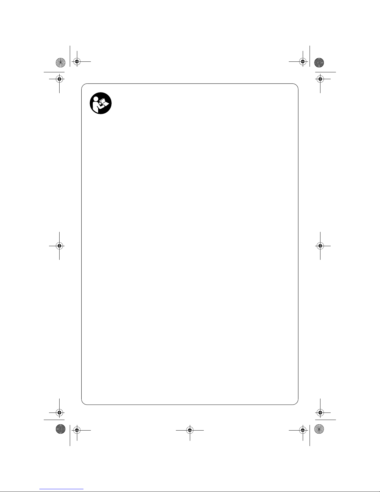
Geräteelemente
Bitte klappen Sie die Aufklappseite mit der Darstellung des Elektrowerkzeugs auf, und lassen Sie diese
Seite aufgeklappt, während Sie die Betriebsanleitung lesen.
Die Nummerierung der Geräteelemente bezieht sich
auf die Darstellung des Elektrowerkzeuges auf der
Grafikseite.
1 Werkzeugaufnahme SDS-plus
2 Staubschutzkappe
3 Verriegelungshülse
4 Verriegelungsring für Werkzeugaufnahme
5 Schlag-/Drehstopp-Schalter
6 Vibrationsdämpfung
7 Ein-/Ausschalter
OBJ_BUCH-820-001.book Page 6 Monday, August 18, 2008 10:25 AM
Page 7
Deutsch–7
18.8.08
8 Drehrichtungsumschalter
9 Taste für Tiefenanschlageinstellung
10 Zusatzgriff
11 Tiefenanschlag
12 Schnellspann-Wechselbohrfutter*
13 Vordere Hülse des Schnellspann-Wechselbohr-
futters*
14 Haltering des Schnellspann-Wechselbohrfutters *
15 Absaugöffnung Absaugvorrichtung*
16 Klemmschraube Absaugvorrichtung*
17 Tiefenanschlag Absaugvorrichtung*
18 Teleskoprohr Absaugvorrichtung*
19 Flügelschraube Absaugvorrichtung*
20 Führungsrohr Absaugvorrichtung *
Abgebildetes oder beschriebenes Zubehör gehört
nicht zum Standard-Lieferumfang.
Technische Daten
Geräusch-/Vibrationsinformation
Messwerte ermittelt entsprechend EN 60745.
Der A-bewertete Geräuschpegel des Elektrowerk-
zeugs beträgt typischerweise: Schalldruckpegel
93 dB(A); Schallleistungspegel 104 dB(A). Unsicherheit K=2 dB.
Gehörschutz tragen!
Schwingungsgesamtwerte (Vektorsumme dreier
Richtungen) ermittelt entsprechend EN 60745:
Hammerbohren in Beton: Schwingungsemissionswert a
h
=8 m/s2, Unsicherheit K=1,5 m/s2,
Meißeln: Schwingungsemissionswert a
h
=7 m/s2,
Unsicherheit K= 1,5 m/s
2
.
Der in diesen Anweisungen angegebene Schwingungspegel ist entsprechend einem in EN 60745
genormten Messverfahren gemessen worden und
kann für den Vergleich von Elektrowerkzeugen miteinander verwendet werden. Er eignet sich auch für
eine vorläufige Einschätzung der Schwingungsbelastung.
Der angegebene Schwingungspegel repräsentiert
die hauptsächlichen Anwendungen des Elektrowerkzeugs. Wenn allerdings das Elektrowerkzeug für
andere Anwendungen, mit abweichenden Einsatzwerkzeugen oder ungenügender Wartung eingesetzt
wird, kann der Schwingungspegel abweichen. Dies
kann die Schwingungsbelastung über den gesamten
Arbeitszeitraum deutlich erhöhen.
Für eine genaue Abschätzung der Schwingungsbelastung sollten auch die Zeiten berücksichtigt werden, in denen das Gerät abgeschaltet ist oder zwar
läuft, aber nicht tatsächlich im Einsatz ist. Dies kann
die Schwingungsbelastung über den gesamten
Arbeitszeitraum deutlich reduzieren.
Legen Sie zusätzliche Sicherheitsmaßnahmen zum
Schutz des Bedieners vor der Wirkung von Schwingungen fest wie zum Beispiel: Wartung von Elektrowerkzeug und Einsatzwerkzeugen, Warmhalten der
Hände, Organisation der Arbeitsabläufe.
Konformitätserklärung
Wir erklären in alleiniger Verantwortung, dass das
unter „Technische Daten“ beschriebene Produkt mit
den folgenden Normen oder normativen Dokumenten übereinstimmt: EN 60745 gemäß den Bestimmungen der Richtlinien 2004/108/EG, 98/37/EG
(bis 28.12.2009), 2006/42/EG (ab 29.12.2009).
Technische Unterlagen bei:
Adolf Würth GmbH & Co.KG, PFW,
D-74650 Künzelsau
Künzelsau, den 09.07.2008
Adolf Würth GmbH & Co. KG
Bohrhammer BMH 32-XE
Art.-Nr. 0702 543 X
Nennaufnahmeleistung W 900
Nenndrehzahl min
-1
0–760
Schlagzahl min
-1
0–3600
Einzelschlagstärke J 5,0
Meißelstellungen 12
Werkzeugaufnahme SDS-plus
Schmierung Zentrale
Dauerschmierung
max. Bohr-Ø
– Beton (mit Wendelboh-
rer)
–Mauerwerk (mit Hohl-
bohrkrone)
–Stahl
–Holz
mm
mm
mm
mm
32
90
13
32
Gewicht entsprechend
EPTA-Procedure
01/2003 kg 4,7
Schutzklasse /II
Angaben gelten für Nennspannungen [U] 230/240 V.
P. Zürn A. Kräutle
OBJ_BUCH-820-001.book Page 7 Monday, August 18, 2008 10:25 AM
Page 8
8–Deutsch
18.8.08
Zusatzgriff
❏ Ziehen Sie vor allen Arbeiten am Elektro-
werkzeug den Netzstecker aus der Steckdose.
❏ Verwenden Sie Ihr Elektrowerkzeug nur
mit dem Zusatzgriff 10.
Sie können den Zusatzgriff 10 beliebig schwenken,
um eine sichere und ermüdungsarme Arbeitshaltung
zu erreichen.
Drehen Sie das untere Griffstück des Zusatzgriffs 10
entgegen dem Uhrzeigersinn und schwenken Sie
den Zusatzgriff 10 in die gewünschte Position.
Danach drehen Sie das untere Griffstück des Zusatzgriffs 10 im Uhrzeigersinn wieder fest.
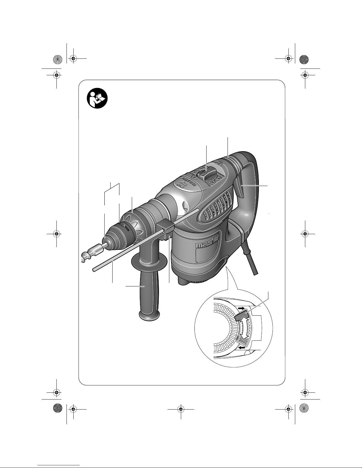
Bohrtiefe einstellen (siehe Bild A)
Mit dem Tiefenanschlag 11 kann die gewünschte
Bohrtiefe X festgelegt werden.
Drücken Sie die Taste für die Tiefenanschlageinstellung 9 und setzen Sie den Tiefenanschlag in den
Zusatzgriff 10 ein.
Schieben Sie das SDS-plus-Einsatzwerkzeug bis zum
Anschlag in die Werkzeugaufnahme SDS-plus 1. Die
Beweglichkeit des SDS-plus-Werkzeugs kann sonst
zu einer falschen Einstellung der Bohrtiefe führen.
Ziehen Sie den Tiefenanschlag so weit heraus, dass
der Abstand zwischen der Spitze des Bohrers und der
Spitze des Tiefenanschlags der gewünschten
Bohrtiefe X entspricht.
Die Riffelung am Tiefenanschlag 11 muss nach
unten zeigen.
Werkzeugaufnahme auswählen
Zum Hammerbohren benötigen Sie SDS-plus-Werkzeuge, die in die Werkzeugaufnahme SDS-plus 1
eingesetzt werden.
Zum Bohren ohne Schlag in Holz, Metall, Keramik
und Kunststoff sowie zum Schrauben und Gewindeschneiden werden Werkzeuge ohne SDS-plus (z. B.
Bohrer mit zylindrischem Schaft) verwendet. Für
diese Werkzeuge benötigen Sie ein Schnellspannbohrfutter.
☞
Hinweis: Verwenden Sie Werkzeuge ohne
SDS-plus nicht zum Hammerbohren oder
Meißeln! Werkzeuge ohne SDS-plus und ihr
Bohrfutter werden beim Hammerbohren und
Meißeln beschädigt.
Die Werkzeugaufnahme SDS-plus 1 kann leicht
gegen das Schnellspann-Wechselbohrfutter 12 ausgetauscht werden.
Werkzeugaufnahme wechseln
Werkzeugaufnahme SDS-plus bzw.
Schnellspann-Wechselbohrfutter
demontieren (siehe Bild B)
Ziehen Sie den Verriegelungsring der Werkzeugaufnahme 4 kräftig in Pfeilrichtung, halten Sie ihn in
dieser Position fest und ziehen Sie die Werkzeugaufnahme 1 bzw. das Schnellspann-Wechselbohrfutter
12 nach vorn ab.
Schützen Sie die Werkzeugaufnahme 1 bzw. das
Schnellspann-Wechselbohrfutter 12 nach dem
Abnehmen vor Verschmutzung. Schmieren Sie bei
Bedarf die Mitnahmeverzahnung leicht.
Werkzeugaufnahme bzw. Schnellspann-Wechselbohrfutter montieren
Umgreifen Sie die Werkzeugaufnahme 1 bzw. das
Schnellspann-Wechselbohrfutter 12 mit der ganzen
Hand. Schieben Sie die Werkzeugaufnahme 1 bzw.
das Schnellspann-Wechselbohrfutter 12 drehend
auf die Bohrfutteraufnahme, bis Sie ein deutliches
Einrastgeräusch hören.
Die Werkzeugaufnahme 1 bzw. das SchnellspannWechselbohrfutter 12 verriegelt sich selbsttätig.
Überprüfen Sie die Verriegelung durch Ziehen an
der Werkzeugaufnahme.
Werkzeugwechsel
Mit der Werkzeugaufnahme SDS-plus können Sie
das Einsatzwerkzeug einfach und bequem ohne Verwendung zusätzlicher Werkzeuge wechseln.
Das SDS-plus-Einsatzwerkzeug ist systembedingt frei
beweglich. Dadurch entsteht beim Leerlauf eine
Rundlaufabweichung. Dies hat keine Auswirkungen
auf die Genauigkeit des Bohrlochs, da sich der Bohrer beim Bohren selbst zentriert.
Die Staubschutzkappe 2 verhindert weitgehend das
Eindringen von Bohrstaub in die Werkzeugaufnahme während des Betriebes. Achten Sie beim Einsetzen des Werkzeuges darauf, dass die
Staubschutzkappe 2 nicht beschädigt wird.
❏ Eine beschädigte Staubschutzkappe ist
sofort zu ersetzen. Es wird empfohlen,
dies von einem Kundendienst vornehmen
zu lassen.
OBJ_BUCH-820-001.book Page 8 Monday, August 18, 2008 10:25 AM
Page 9
Deutsch–9
18.8.08
SDS-plus-Einsatzwerkzeug einsetzen (siehe Bild C)
Reinigen Sie das Einsteckende des Einsatzwerkzeuges und fetten Sie es leicht ein.
Setzen Sie das Einsatzwerkzeug drehend in die
Werkzeugaufnahme ein, bis es selbsttätig verriegelt
wird.
Überprüfen Sie die Verriegelung durch Ziehen am
Werkzeug.
SDS-plus-Einsatzwerkzeug entnehmen (siehe Bild D)
Schieben Sie die Verriegelungshülse 3 nach hinten
und entnehmen Sie das Einsatzwerkzeug.
Einsatzwerkzeuge ohne SDS-plus
einsetzen (siehe Bild E)
☞
Hinweis: Verwenden Sie Werkzeuge ohne
SDS-plus nicht zum Hammerbohren oder
Meißeln! Werkzeuge ohne SDS-plus und ihr
Bohrfutter werden beim Hammerbohren und
Meißeln beschädigt.
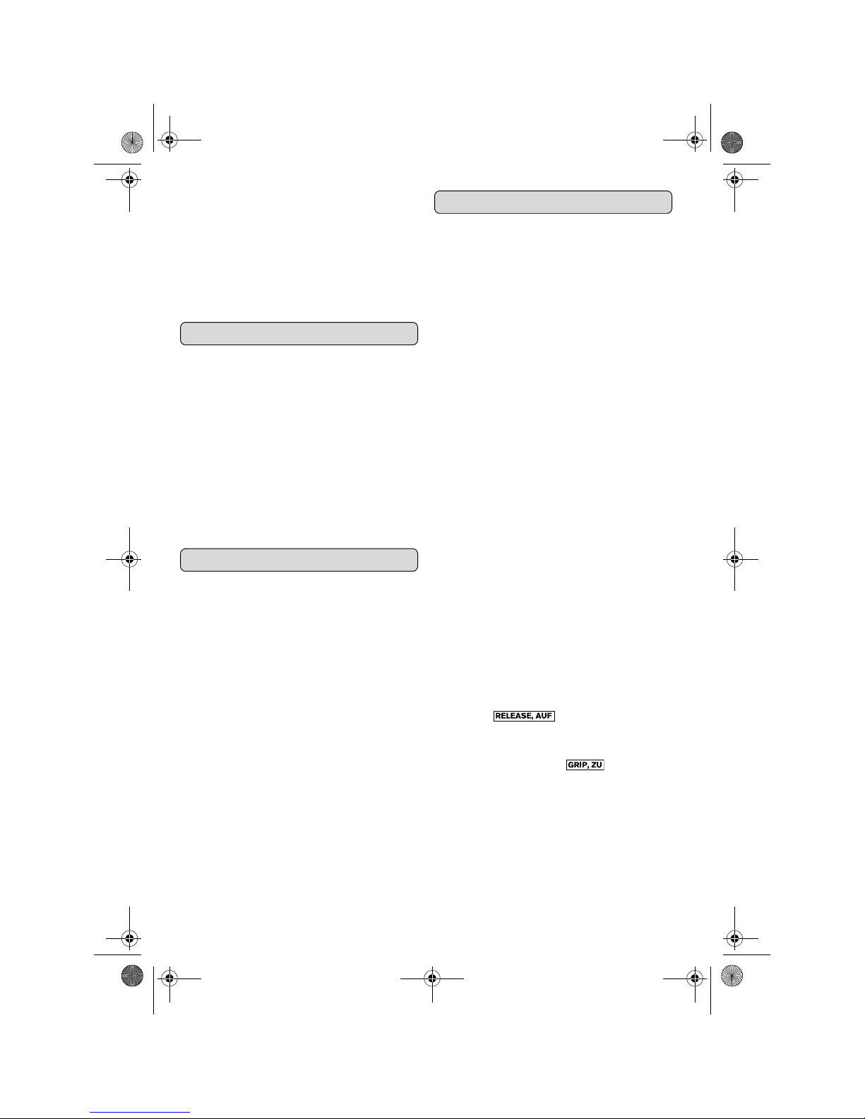
Setzen Sie das Schnellspann-Wechselbohrfutter 12
ein.
Halten Sie den Haltering des Schnellspann-Wechselbohrfutters 12 fest. Öffnen Sie die Werkzeugaufnahme durch Drehen der vorderen Hülse in
Richtung des Symbols „ “.
Setzen Sie das Einsatzwerkzeug in das SchnellspannWechselbohrfutter 12 ein. Halten Sie den Haltering
des Schnellspann-Wechselbohrfutters 12 fest und
drehen Sie die vordere Hülse in Richtung des Symbols „ “.
Prüfen Sie den festen Sitz durch Ziehen am Werkzeug.
☞
Hinweis: Wurde die Werkzeugaufnahme bis
zum Anschlag geöffnet, kann beim Zudrehen
der Werkzeugaufnahme das Ratschengeräusch zu hören sein und die Werkzeugaufnahme schließt sich nicht.
Drehen Sie in diesem Fall die vordere Hülse
13 einmal entgegen der Pfeilrichtung.
Danach kann die Werkzeugaufnahme
geschlossen werden.
Drehen Sie den Schlag-/Drehstopp-Schalter 5 in die
Position „Bohren“.
Einsatzwerkzeuge ohne SDS-plus
entnehmen (siehe Bild E)
Halten Sie den Haltering des Schnellspann-Wechselbohrfutters 12 fest. Öffnen Sie die Werkzeugaufnahme durch Drehen der vorderen Hülse in
Richtung des Symbols „ “.
Entnehmen Sie das Einsatzwerkzeug.
Staubabsaugung mit Absaugvorrichtung
(Zubehör)
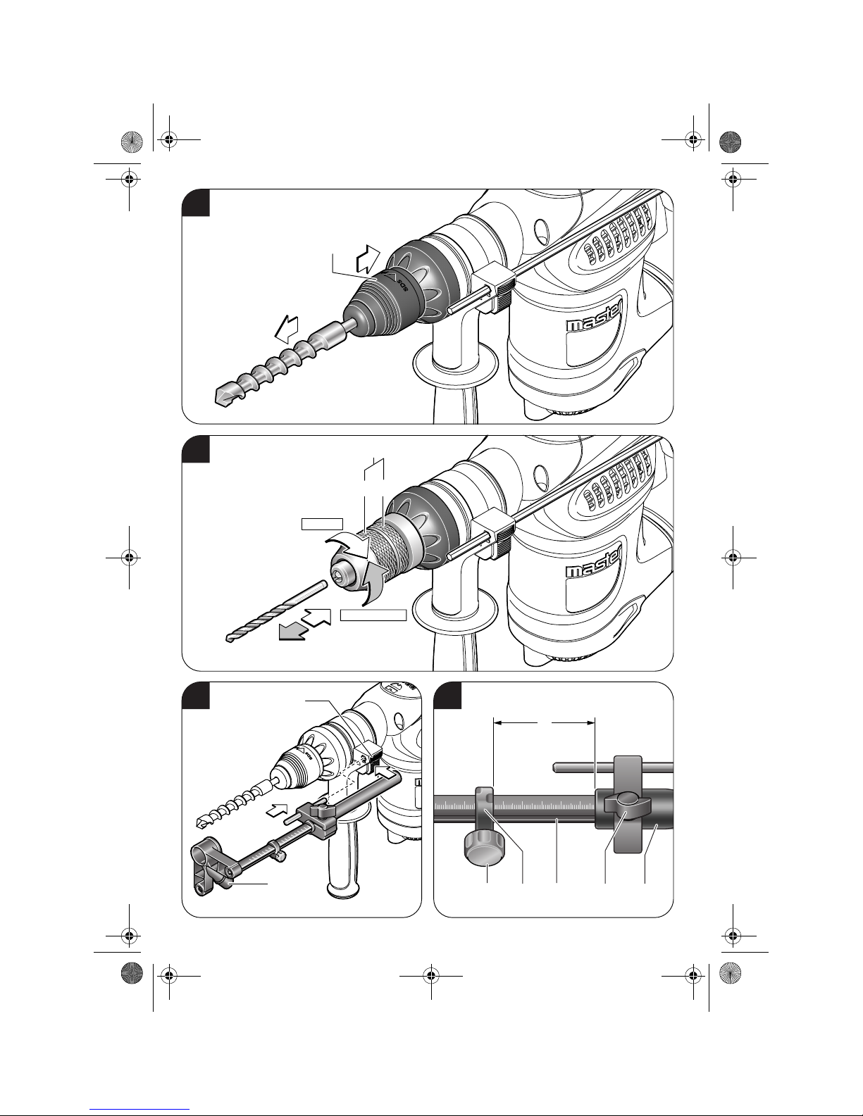
Absaugvorrichtung montieren
(siehe Bild F)
Für die Staubabsaugung wird eine Absaugvorrichtung (Zubehör) benötigt. Beim Bohren federt die
Absaugvorrichtung zurück, sodass der Absaugvorrichtungs-Kopf immer dicht am Untergrund gehalten wird.
Drücken Sie die Taste für die Tiefenanschlageinstellung 9 und entnehmen Sie den Tiefenanschlag 11.
Drücken Sie die Taste 9 erneut und setzen Sie die
Absaugvorrichtung von vorn in den Zusatzgriff 10
ein.
Schließen Sie einen Absaugschlauch an die Absaugöffnung 15 der Absaugvorrichtung an.
Der Staubsauger muss für den zu bearbeitenden
Werkstoff geeignet sein.
Verwenden Sie beim Absaugen von besonders
gesundheitsgefährdenden, krebserzeugenden oder
trockenen Stäuben einen Spezialsauger.
In Deutschland werden für Holzstäube auf Grund
TRGS 553 geprüfte Absaugeinrichtungen gefordert,
die interne Absaugvorrichtung darf im gewerblichen
Bereich nicht verwendet werden. Für andere Materialien muss der gewerbliche Betreiber die speziellen
Anforderungen mit der zuständigen Berufsgenossenschaft klären.
Bohrtiefe am Absaugvorrichtung
einstellen (siehe Bild G)
Sie können die gewünschte Bohrtiefe X auch bei
montierter Absaugvorrichtung festlegen.
Schieben Sie das SDS-plus-Einsatzwerkzeug bis zum
Anschlag in die Werkzeugaufnahme SDS-plus 1. Die
Beweglichkeit des SDS-plus-Werkzeugs kann sonst
zu einer falschen Einstellung der Bohrtiefe führen.
Lösen Sie die Flügelschraube 19 an der Absaugvorrichtung.
Setzen Sie das Elektrowerkzeug ohne es einzuschalten fest auf die zu bohrende Stelle auf. Das SDSplus-Einsatzwerkzeug muss dabei auf der Fläche
aufsetzen.
Verschieben Sie das Führungsrohr 20 der Absaugvorrichtung so in seiner Halterung, dass der Absaugvorrichtungs-Kopf auf der zu bohrenden Fläche
aufliegt. Schieben Sie das Führungsrohr 20 nicht
weiter über das Teleskoprohr 18 als nötig, sodass
ein möglichst großer Teil der Skala auf dem
Teleskoprohr 18 sichtbar bleibt.
Ziehen Sie die Flügelschraube 19 wieder fest. Lösen
Sie die Klemmschraube 16 am Tiefenanschlag der
Absaugvorrichtung.
OBJ_BUCH-820-001.book Page 9 Monday, August 18, 2008 10:25 AM
Page 10
10–Deutsch
18.8.08
Verschieben Sie den Tiefenanschlag 17 so auf dem
Teleskoprohr 18, dass der im Bild gezeigte Abstand
X Ihrer gewünschten Bohrtiefe entspricht.
Ziehen Sie die Klemmschraube 16 in dieser Position
fest.
Inbetriebnahme
❏ Beachten Sie die Netzspannung! Die
Spannung der Stromquelle muss mit den
Angaben auf dem Typenschild des Elektrowerkzeuges übereinstimmen. Mit
230 V gekennzeichnete Elektrowerkzeuge können auch an 220 V betrieben
werden.
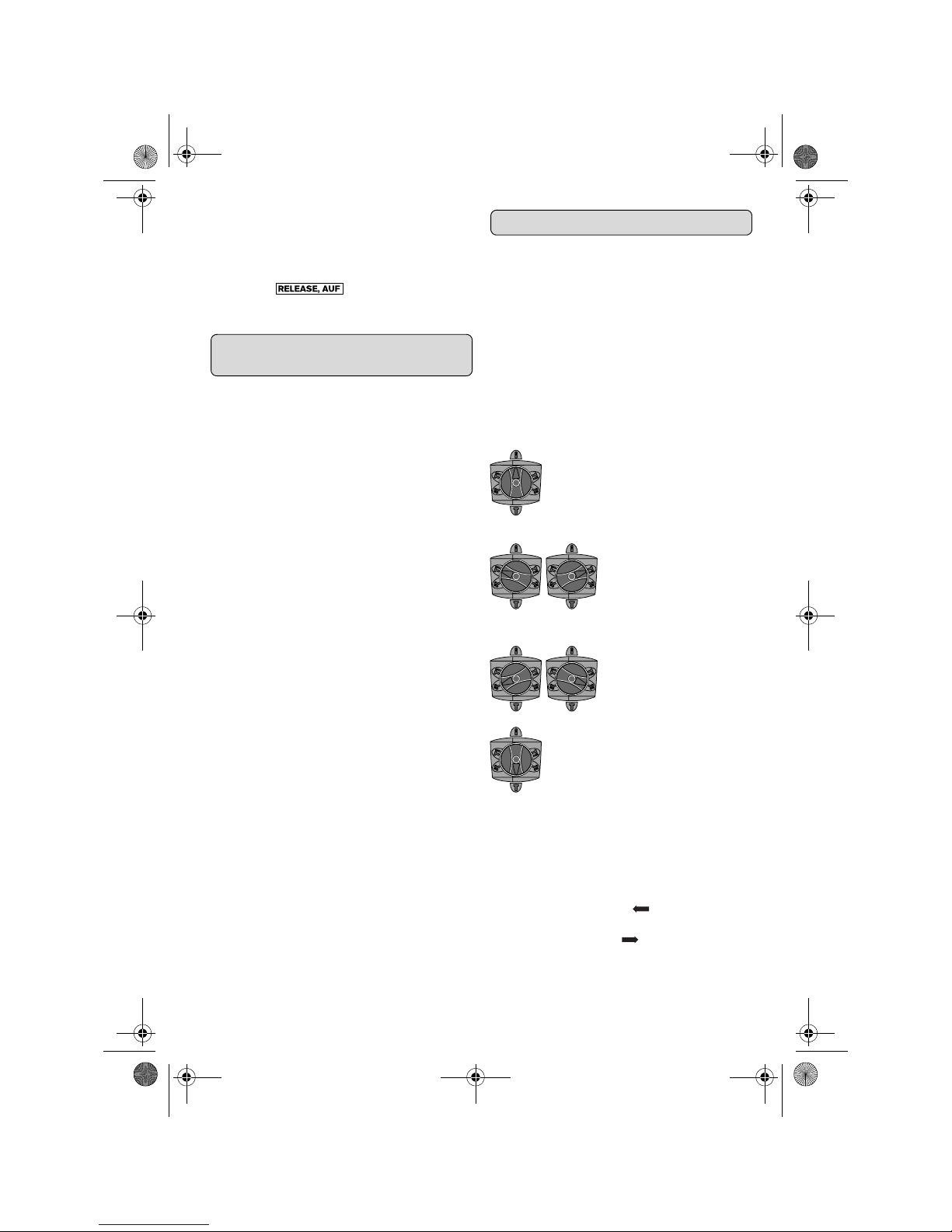
Betriebsart einstellen
Mit dem Schlag-/Drehstopp-Schalter 5 wählen Sie
die Betriebsart des Elektrowerkzeugs.
☞
Hinweis: Ändern Sie die Betriebsart nur bei
ausgeschaltetem Elektrowerkzeug! Das Elektrowerkzeug kann sonst beschädigt werden.
Drehen Sie den Schlag-/Drehstopp-Schalter 5 auf
die gewünschte Stellung.
Drehrichtung einstellen
❏ Betätigen Sie den Drehrichtungsumschal-
ter 8 nur bei Stillstand des Elektrowerkzeuges.
Mit dem Drehrichtungsumschalter 8 können Sie die
Drehrichtung des Elektrowerkzeuges ändern.
Rechtslauf: Drehen Sie den Drehrichtungsumschalter 8 bis zum Anschlag in Position .
Linkslauf: Drehen Sie den Drehrichtungsumschalter 8 bis zum Anschlag in Position .
Stellen Sie die Drehrichtung zum Hammerbohren,
Bohren und Meißeln immer auf Rechtslauf.
Ein-/Ausschalten
Drücken Sie zur Inbetriebnahme des Elektrowerkzeuges den Ein-/Ausschalter 7 und halten Sie ihn
gedrückt.
Um das Elektrowerkzeug auszuschalten lassen Sie
den Ein-/Ausschalter 7 los.
Bei niedrigen Temperaturen erreicht das Elektrowerkzeug erst nach einer gewissen Zeit die volle
Hammerleistung/Schlagleistung.
Drehzahl/Schlagzahl einstellen
Sie können die Drehzahl/Schlagzahl des eingeschalteten Elektrowerkzeugs stufenlos regulieren, je nachdem, wie weit Sie den Ein-/Ausschalter 7
eindrücken.
Leichter Druck auf den Ein-/Ausschalter 7 bewirkt
eine niedrige Drehzahl/Schlagzahl. Mit zunehmendem Druck erhöht sich die Drehzahl/Schlagzahl.
Überlastkupplung
❏ Klemmt oder hakt das Einsatzwerkzeug,
wird der Antrieb zur Bohrspindel unterbrochen. Halten Sie, wegen der dabei auftretenden Kräfte, das Elektrowerkzeug
immer mit beiden Händen gut fest und
nehmen Sie einen festen Stand ein.
❏ Schalten Sie das Elektrowerkzeug aus und
lösen Sie das Einsatzwerkzeug, wenn das
Elektrowerkzeug blockiert. Beim Einschalten mit einem blockierten Bohrwerkzeug
entstehen hohe Reaktionsmomente.
Verändern der Meißelstellung
Sie können den Meißel in 12 Stellungen arretieren.
Dadurch können Sie die jeweils optimale Arbeitsposition einnehmen.
Setzen Sie den Meißel in die Werkzeugaufnahme
ein.
Drehen Sie den Schlag-/Drehstopp-Schalter 5 in die
Position „Meißelverstellung“ (siehe „Betriebsart einstellen“, Seite 10).
Drehen Sie das Einsatzwerkzeug in die gewünschte
Meißelstellung.
Drehen Sie den Schlag-/Drehstopp-Schalter 5 in die
Position „Meißeln“. Die Werkzeugaufnahme ist
damit arretiert.
Stellen Sie die Drehrichtung zum Meißeln auf Rechtslauf.
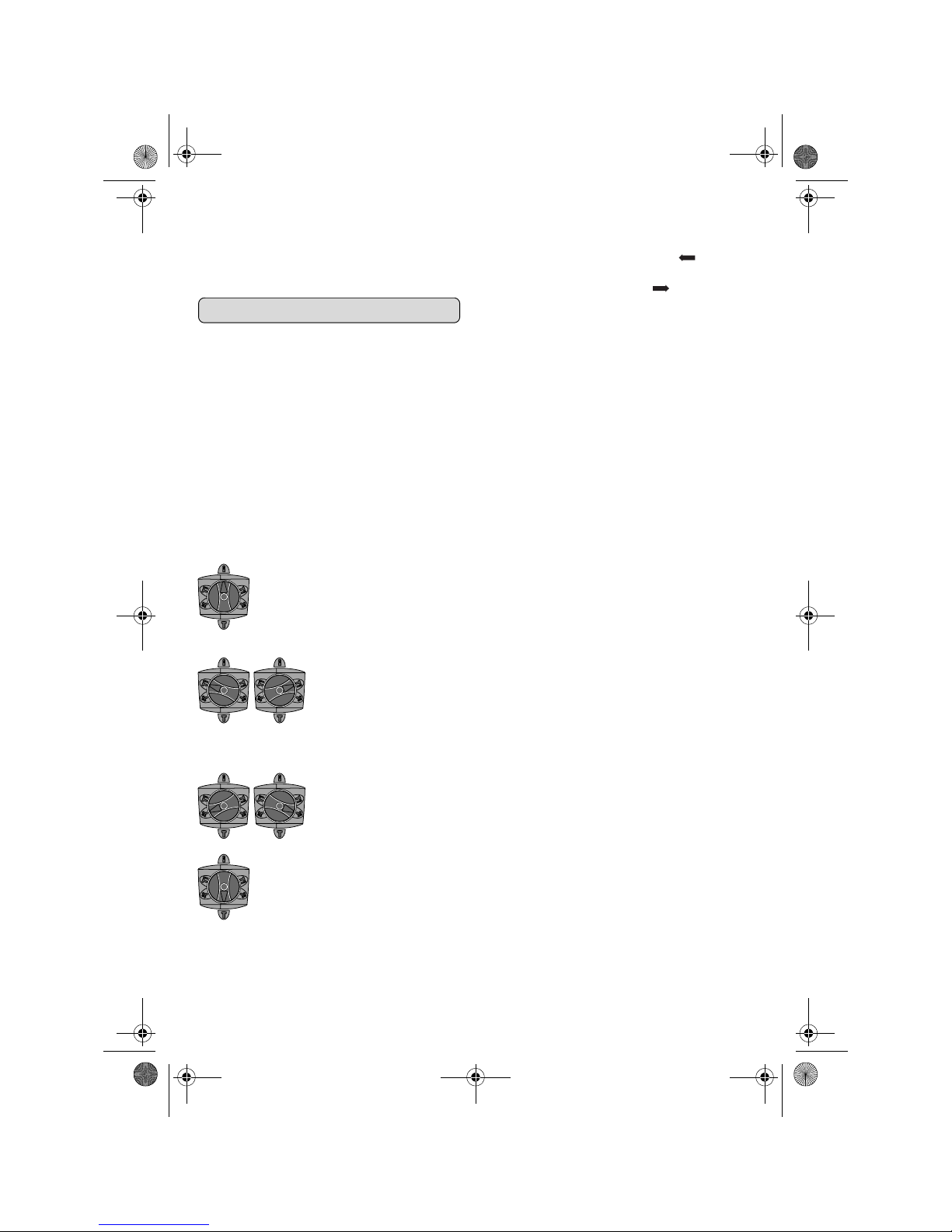
Position zum Bohren ohne
Schlag in Holz, Metall, Keramik und Kunststoff sowie zum
Schrauben und Gewindeschneiden
Position zum Hammerboh-
ren in Beton oder Stein
Falls sich das Einsatzwerkzeug beim Einschalten nicht
sofort dreht, lassen Sie das
Elektrowerkzeug langsam
laufen, bis sich das Einsatzwerkzeug mitdreht.
Position zum Verstellen der
Meißelposition
Position zum Meißeln
OBJ_BUCH-820-001.book Page 10 Monday, August 18, 2008 10:25 AM
Page 11

Deutsch–11
18.8.08
Wartung und Reinigung
❏ Ziehen Sie vor allen Arbeiten am Elektro-
werkzeug den Netzstecker aus der Steckdose.
❏ Halten Sie das Elektrowerkzeug und die
Lüftungsschlitze sauber, um gut und
sicher zu arbeiten.
❏ Eine beschädigte Staubschutzkappe ist
sofort zu ersetzen. Es wird empfohlen,
dies von einem Kundendienst vornehmen
zu lassen.
Sollte das Elektrowerkzeug trotz sorgfältiger Herstellungs- und Prüfverfahren einmal ausfallen, ist die
Reparatur von einem Würth master-Service ausführen zu lassen. In Deutschland erreichen Sie den
Würth master-Service kostenlos unter Tel. 0800WMASTER (0800-9627837), in Österreich unter
Tel. 0800-20 30 13.
Geben Sie bei allen Rückfragen und Ersatzteilbestellungen bitte unbedingt die Artikelnummer laut
Typenschild des Elektrowerkzeuges an.
Die aktuelle Ersatzteilliste dieses Elektrowerkzeuges
kann im Internet unter
„http://www.wuerth.com/partsmanager“
aufgerufen oder von der nächstgelegenen WürthNiederlassung angefordert werden.
Gewährleistung
Für dieses Würth-Elektrowerkzeug bieten wir eine
Gewährleistung gemäß den gesetzlichen/länderspezifischen Bestimmungen ab Kaufdatum (Nachweis durch Rechnung oder Lieferschein).
Entstandene Schäden werden durch Ersatzlieferung
oder Reparatur beseitigt.
Schäden, die auf natürliche Abnutzung, Überlastung
oder unsachgemäße Behandlung zurückzuführen
sind, werden von der Gewährleistung ausgeschlossen.
Beanstandungen können nur anerkannt werden,
wenn Sie das Elektrowerkzeug unzerlegt einer
Würth-Niederlassung, Ihrem Würth-Außendienstmitarbeiter oder einer Würth-autorisierten Kundendienststelle für Elektrowerkzeuge übergeben.
Entsorgung
Elektrowerkzeuge, Zubehör und Verpackungen sollen einer umweltgerechten Wiederverwertung zugeführt werden.
Nur für EU-Länder:
Werfen Sie Elektrowerkzeuge nicht in den
Hausmüll!
Gemäß der Europäischen Richtlinie
2002/96/EG über Elektro- und Elektro-
nik-Altgeräte und ihrer Umsetzung in
nationales Recht müssen nicht mehr gebrauchsfähige Elektrowerkzeuge getrennt gesammelt und
einer umweltgerechten Wiederverwertung zugeführt
werden.
Änderungen vorbehalten.
OBJ_BUCH-820-001.book Page 11 Monday, August 18, 2008 10:25 AM
Page 12
12– English
18.8.08
For Your Safety
Read all safety warnings and all
instructions. Failure to follow the
warnings and instructions may result in
electric shock, fire and/or serious
injury.
❏ See data sheet for further safety warnings
and instructions.
❏ Wear hearing protection. Exposure to noise
can cause hearing loss.
❏ Use auxiliary handle(s), if supplied with
the tool. Loss of control can cause personal
injury.
❏ Use suitable detectors to determine if util-
ity lines are hidden in the work area or
call the local utility company for assistance. Contact with electric lines can lead to fire
and electric shock. Damaging a gas line can lead
to explosion. Penetrating a water line causes
property damage or may cause an electric shock.
❏ Hold the power tool only by the insulated
gripping surfaces when performing an
operation where the cutting tool may contact hidden wiring or its own cord. Contact
with a “live” wire will also make exposed metal
parts of the power tool “live” and shock the operator.
❏ When working with the machine, always
hold it firmly with both hands and provide
for a secure stance. The power tool is guided
more secure with both hands.
❏ Secure the workpiece. A workpiece clamped
with clamping devices or in a vice is held more
secure than by hand.
❏ Do not work materials containing asbes-
tos. Asbestos is considered carcinogenic.
❏ Take protective measures when dust can
develop during working that is harmful to
one’s health, combustible or explosive.
Example: Some dusts are regarded as carcinogenic. Wear a dust mask and work with dust/chip
extraction when connectable.
❏ Keep your workplace clean. Blends of mate-
rials are particularly dangerous. Dust from light
alloys can burn or explode.
❏ Always wait until the machine has come to
a complete stop before placing it down.
The tool insert can jam and lead to loss of control
over the power tool.
❏ Never use the machine with a damaged
cable. Do not touch the damaged cable
and pull the mains plug when the cable is
damaged while working. Damaged cables
increase the risk of an electric shock.
❏ Use only original Würth accessories.
Intended Use
The machine is intended for hammer drilling in concrete, brick and stone, as well as for light chiselling
work. It is also suitable for drilling without impact in
wood, metal, ceramic and plastic.
For damage caused by usage other than intended,
the user is responsible.
Product Features
While reading the operating instructions, unfold the
graphics page for the machine and leave it open.
The numbering of the product features refers to the
illustration of the power tool on the graphics page.
1 SDS-plus tool holder
2 Dust protection cap
3 Locking sleeve
4 Lock ring of the tool holder
5 Mode selector switch
6 Vibration damper
7 On/Off switch
8 Rotational direction switch
9 Button for depth stop adjustment
10 Auxiliary handle
11 Depth stop
12 Quick change keyless chuck*
13 Front sleeve of the quick change keyless chuck*
14 Retaining ring of the quick change keyless chuck*
15 Extraction sleeve of the extraction device*
OBJ_BUCH-820-001.book Page 12 Monday, August 18, 2008 10:25 AM
Page 13
English–13
18.8.08
16 Clamping screw of the extraction device*
17 Depth stop of the extraction device*
18 Telescopic pipe of the extraction device*
19 Wing bolt of the extraction device*
20 Guide tube of the extraction device*
The accessories illustrated or described are not
included as standard delivery.
Technical Data
Noise/Vibration Information
Measured values determined according to
EN 60745.
Typically the A-weighted noise levels of the product
are: Sound pressure level 93 dB(A); Sound power
level 104 dB(A). Uncertainty K =2 dB.
Wear hearing protection!
Vibration total values (triax vector sum) determined
according to EN 60745:
Hammer drilling into concrete: Vibration emission
value a
h
=8 m/s2, Uncertainty K=1.5 m/s2,
Chiselling: Vibration emission value a
h
=7 m/s2,
Uncertainty K= 1.5 m/s
2
.
The vibration emission level given in this information
sheet has been measured in accordance with a
standardised test given in EN 60745 and may be
used to compare one tool with another. It may be
used for a preliminary assessment of exposure.
The declared vibration emission level represents the
main applications of the tool. However if the tool is
used for different applications, with different accessories or poorly maintained, the vibration emission
may differ. This may significantly increase the exposure level over the total working period.
An estimation of the level of exposure to vibration
should also take into account the times when the tool
is switched off or when it is running but not actually
doing the job. This may significantly reduce the
exposure level over the total working period.
Identify additional safety measures to protect the
operator from the effects of vibration such as: maintain the tool and the accessories, keep the hands
warm, organisation of work patterns.
Declaration of Conformity
We declare under our sole responsibility that the
product described under “Technical Data” is in conformity with the following standards or standardization documents: EN 60745 according to the
provisions of the directives 2004/108/EC,
98/37/EC (until 28 Dec 2009), 2006/42/EC (from
29 Dec 2009).
Technical file at:
Adolf Würth GmbH & Co.KG, PFW,
D-74650 Künzelsau
Künzelsau, 09.07.2008
Adolf Würth GmbH & Co. KG
Auxiliary Handle
❏ Before any work on the machine itself,
pull the mains plug.
❏ Operate your machine only with the auxil-
iary handle 10.
The auxiliary handle 10 can be set to any position
for a secure and low-fatigue working posture.
Turn the bottom part of the auxiliary handle 10 in
counterclockwise direction and swivel the auxiliary
handle 10 to the desired position. Then retighten the
bottom part of the auxiliary handle 10 by turning in
clockwise direction.
Adjusting the Drilling Depth
(see figure A)
The required drilling depth X can be set with the
depth stop 11.
Press the button for the depth stop adjustment 9 and
insert the depth stop into the auxiliary handle 10.
Rotary Hammer BMH 32-XE
Art. No. 0702 543 X
Rated power input W 900
Rated speed min
-1
0–760
Impact rate min
-1
0–3600
Impact energy per stroke J 5.0
Chisel positions 12
Tool holder SDS-plus
Lubrication Central
permanent
lubrication
Max. drilling dia.
– Concrete (with twist
drill)
– Brickwork (with core
bit)
–Steel
– Wood
mm
mm
mm
mm
32
90
13
32
Weight according to
EPTA-Procedure
01/2003 kg 4.7
Protection class /II
The values given apply for nominal voltages [U] of
230/240 V.
P. Zürn A. Kräutle
OBJ_BUCH-820-001.book Page 13 Monday, August 18, 2008 10:25 AM
Page 14
14– English
18.8.08
Insert the SDS-plus drilling tool to the stop into the
SDS-plus tool holder 1. Otherwise, the movability of
the SDS-plus drilling tool can lead to incorrect
adjustment of the drilling depth.
Pull out the depth stop until the distance between the
tip of the drill bit and the tip of the depth stop correspond with the desired drilling depth X.
The knurled surface of the depth stop 11 must face
downward.
Selecting the Tool Holder
For hammer drilling, SDS-plus drilling tools that can
be inserted into the SDS-plus tool holder 1 are
required.
For drilling without impact in wood, metal, ceramic
and plastic as well as for screwdriving and tapping,
use non-SDS-plus drilling tools (e. g., drill bits with
cylindrical shank). A keyless drill chuck is required
for such drilling tools.
☞
Note: Do not use tools without SDS-plus for
hammer drilling or chiselling! Tools without
SDS-plus and their drill chucks are damaged
by hammer drilling or chiselling.
The SDS-plus tool holder 1 can easily be exchanged
against the quick change keyless chuck 12.
Changing the Tool Holder
Dismounting the SDS-plus Tool
Holder or the Quick change keyless
chuck (see figure B)
Pull the lock ring of the tool holder 4 firmly in the
direction of the arrow, hold it in this position and pull
off the tool holder 1 or the keyless replacement
chuck 12 toward the front.
After removing, protect the tool holder 1 or the quick
change keyless chuck 12 against contamination.
Lightly lubricate the engaging grooves, if required.
Mounting the SDS-plus Tool Holder
or the Quick change keyless chuck
Grasp the tool holder 1 or the keyless replacement
chuck 12 completely with your hand. Slide the tool
holder 1 or the keyless replacement chuck 12 with a
turning motion onto the drill chuck mounting until a
distinct latching noice is heard.
The tool holder 1 or the quick change keyless chuck
12 is automatically locked. Check the locking effect
by pulling the tool holder.
Changing the Tool
With the SDS-plus tool holder, simple and convenient
tool changing is possible without additional aids.
As a requirement of the system, the SDS-plus drilling
tool can move freely. This causes a certain radial
run-out at no-load, which has no effect on the accuracy of the drill hole, as the drill bit centres itself
upon drilling.
The dust protection cap 2 largely prevents the entry
of drilling dust into the tool holder during operation.
When inserting the tool, take care that the dust protection cap 2 is not damaged.
❏ A damaged dust protection cap should be
changed immediately. We recommend
having this carried out by an after-sales
service.
Inserting SDS-plus Drilling Tools
(see figure C)
Clean and lightly grease the shank end of the tool.
Insert the tool in a twisting manner into the tool
holder until it latches itself.
Check the latching by pulling the tool.
Removing SDS-plus Drilling Tools
(see figure D)
Push back the locking sleeve 3 and remove the tool.
Inserting Drilling Tools without SDSplus (see figure E)
☞
Note: Do not use tools without SDS-plus for
hammer drilling or chiselling! Tools without
SDS-plus and their drill chucks are damaged
by hammer drilling or chiselling.
Insert the quick change keyless chuck 12.
Firmly hold the retaining ring of the quick change
keyless chuck 12. Open the quick change keyless
chuck by turning the front sleeve in the direction of
the symbol “ ”.
Insert the drilling tool into the quick change keyless
chuck 12. Firmly hold the retaining ring of the quick
change keyless chuck 12 and turn the front sleeve in
the direction of the symbol “ ”.
Check the tight seating by pulling the tool.
☞
Note: If the tool holder was opened to the
stop, then the latching noise possibly may be
heard while closing the tool holder and the
tool holder will not close.
In this case, turn the front sleeve 13 once in
the opposite direction of the arrow. Afterwards, the tool holder can be closed (tight-
ened) again.
Turn the mode selector switch 5 to the “drilling”
position.
OBJ_BUCH-820-001.book Page 14 Monday, August 18, 2008 10:25 AM
Page 15
English–15
18.8.08
Removing Drilling Tools without
SDS-plus (see figure E)
Firmly hold the retaining ring of the quick change
keyless chuck 12. Open the quick change keyless
chuck by turning the front sleeve in the direction of
the symbol “ ”.
Remove the drilling tool.
Dust Extraction with the Extraction Device
(Accessory)
Mounting the Extraction Device
(see figure F)
An extraction device (accessory) is required for dust
extraction. When drilling, the extraction device
retracts so that the head of the extraction device is
always positioned close to the surface.
Press the button for depth stop adjustment 9 and
remove the depth stop 11. Press button 9 again and
insert the extraction device from the front into the
auxiliary handle 10.
Connect a vacuum hose to the extraction sleeve 15
of the extraction device.
The vacuum cleaner must be suitable for the material being worked.
When vacuuming dry dust that is especially detrimental to health or carcinogenic, use a special vacuum cleaner.
Adjusting the Drilling Depth on the
Extraction Device (see figure G)
The requested drilling depth X can also be set when
the extraction device is mounted.
Insert the SDS-plus drilling tool to the stop into the
SDS-plus tool holder 1. Otherwise, the movability of
the SDS-plus drilling tool can lead to incorrect
adjustment of the drilling depth.
Loosen wing bolt 19 of the extraction device.
Without switching the power tool on, apply it firmly
to the drilling location. The SDS-plus drilling tool
must face against the surface.
Move the guide tube 20 of the extraction device in its
holder in such a manner that the head of the extraction
device faces against the surface to be drilled. Do not
move guide tube 20 further over the telescopic pipe 18
than necessary, so that as much as possible of the scale
remains visible on the telescopic pipe 18.
Tighten wing bolt 19 again. Loosen clamping screw
16 at the depth stop of the extraction device.
Move the depth stop 17 on the telescopic pipe 18 in
such a manner that the clearance X shown in the figure corresponds with the required drilling depth.
Tighten the clamping screw 16 in this position.
Starting Operation
❏ Observe correct mains voltage! The volt-
age of the power source must agree with
the voltage specified on the nameplate of
the machine. Power tools marked with
230 V can also be operated with 220 V.
Setting the Operating Mode
The operating mode of the power tool is selected
with the mode selector switch 5.
☞
Note: Change the operating mode only
when the machine is switched off! Otherwise,
the machine can be damaged.
Turn the mode selector switch 5 to the requested
position.
Reversing the Rotational Direction
❏ Actuate the rotational direction switch 8
only when the machine is at a standstill.
The rotational direction switch 8 is used to reverse
the rotational direction of the machine.
Right rotation: Turn the rotational direction switch
8 to the stop in the position .
Left rotation: Turn the rotational direction switch 8
to the stop in the position .
Set the direction of rotation for hammer drilling,
drilling and chiselling always to right rotation.
Position for drilling without
impact in wood, metal,
ceramic and plastic as well
as for screwdriving and
thread cutting
Position for hammer drill-
ing in concrete or stone
When the drilling tool does
not immediately rotate upon
switching on, allow the
machine to run slowly until
the drilling tool rotates.
Position for changing the
position of the chisel
Position for chiselling
OBJ_BUCH-820-001.book Page 15 Monday, August 18, 2008 10:25 AM
Page 16
16– English
18.8.08
Switching On and Off
To start the machine, press the On/Off switch 7
and keep it pressed.
To switch off the machine, release the On/Off
switch 7.
For low temperatures, the power tool reaches the full
hammer/impact capacity only after a certain time.
Setting the Speed/Impact Rate
The speed/impact rate of the switched on power tool
can be variably adjusted, depending on how far the
On/Off switch 7 is pressed.
Light pressure on the On/Off switch 7 results in low
speed/impact rate. Further pressure on the switch
increases the speed/impact rate.
Safety Clutch
❏ If the tool insert becomes caught or
jammed, the drive to the drill spindle is
interrupted. Because of the forces that
occur, always hold the power tool firmly
with both hands and provide for a secure
stance.
❏ If the power tool jams, switch the machine
off and loosen the tool insert. When
switching the machine on with the drilling
tool jammed, high reaction torques can
occur.
Changing the position of the chisel
The chisel can be locked in 12 positions. In this manner, the optimum working position can be set for
each application.
Insert the chisel into the tool holder.
Turn the mode selector switch 5 into the position
“changing the position of the chisel” (see “Setting the
Operating Mode”, page 15).
Turn the tool holder to the desired chiselling position.
Turn the mode selector switch 5 to the “chiselling”
position. The tool holder is now locked.
For chiselling, set the rotation direction to right rotation.
Maintenance and Cleaning
❏ Before any work on the machine itself,
pull the mains plug.
❏ For safe and proper working, always keep
the machine and ventilation slots clean.
❏ A damaged dust protection cap should be
changed immediately. We recommend
having this carried out by an after-sales
service.
If the machine should fail despite the care taken in
manufacturing and testing procedures, repair
should be carried out by a Würth master-Service.
In all correspondence and spare parts orders, please
always include the article number given on the type
plate of the machine.
The current spare parts list for this power tool can be
viewed in the Internet under
“http://www.wuerth.com/partsmanager”
or be requested from your next Würth branch office.
Guarantee
For this Würth power tool, we provide a guarantee
in accordance with the legal/country-specific regulations from the date of purchase (verified by invoice
or delivery document). Damage that has occurred
will be corrected by replacement or repair.
Damage caused by normal wear, overloading or
improper handling is excluded from the guarantee.
Claims can only be accepted if the power tool is sent
undisassembled to a Würth branch office, your
Würth sales representative or a customer service
agent for Würth power tools.
Disposal
The machine, accessories and packaging should be
sorted for environmental-friendly recycling.
Only for EC countries:
Do not dispose of power tools into household waste!
According to the European Guideline
2002/96/EC for Waste Electrical and
Electronic Equipment and its implementation into national right, power tools that are no
longer usable must be collected separately and disposed of in an environmentally correct manner.
Subject to change without notice.
OBJ_BUCH-820-001.book Page 16 Monday, August 18, 2008 10:25 AM
Page 17
Italiano–17
18.8.08
Per la Vostra sicurezza
Leggere tutte le avvertenze di
pericolo e le istruzioni operative. In
caso di mancato rispetto delle avvertenze
di pericolo e delle istruzioni operative si
potrà creare il pericolo di scosse elettriche, incendi e/o incidenti gravi.
❏ Per ulteriori istruzioni di sicurezza vedi
allegati.
❏ Portare cuffie di protezione. L’effetto del
rumore può provocare la perdita dell’udito.
❏ Utilizzare le impugnature supplementari
fornite insieme all’elettroutensile. La per-
dita di controllo sull’elettroutensile può comportare il pericolo di incidenti.
❏ Al fine di rilevare linee di alimentazione
nascoste, utilizzare adatte apparecchiature di ricerca oppure rivolgersi alla
locale società erogatrice. Un contatto con
linee elettriche può provocare lo sviluppo di
incendi e di scosse elettriche. Danneggiando
linee del gas si può creare il pericolo di esplosioni. Penetrando una tubazione dell’acqua si
provocano seri danni materiali oppure vi è il
pericolo di provocare una scossa elettrica.
❏ Quando si eseguono lavori in cui vi è peri-
colo che l’accessorio impiegato possa arrivare a toccare cavi elettrici nascosti oppure
anche il cavo elettrico della macchina
stessa, tenere l’elettroutensile afferrandolo
sempre alle superfici di impugnatura isolate. Un contatto con un cavo elettrico mette sotto
tensione anche le parti in metallo dell’elettroutensile e provoca quindi una scossa elettrica.
❏ Durante le operazioni di lavoro è neces-
sario tenere l’elettroutensile sempre con
entrambe le mani ed adottare una posizione di lavoro sicura. Utilizzare con sicu-
rezza l’elettroutensile tenendolo sempre con
entrambe le mani.
❏ Assicurare il pezzo in lavorazione. Un
pezzo in lavorazione può essere bloccato con
sicurezza in posizione solo utilizzando un apposito dispositivo di serraggio oppure una morsa a
vite e non tenendolo con la semplice mano.
❏ Non lavorare mai materiali contenenti
amianto. L’amianto è ritenuto materiale cance-
rogeno.
❏ Prendere dei provvedimenti appropriati
in caso che durante il lavoro dovessero
svilupparsi polveri dannose per la salute,
infiammabili oppure esplosive. Ad esem-
pio: Alcune polveri sono considerate cancerogene. Portare una maschera di protezione contro
la polvere ed utilizzare, se collegabile, un sistema
di aspirazione polvere/aspirazione trucioli.
❏ Mantenere pulita la propria zona di
lavoro. Miscele di materiali di diverso tipo pos-
sono risultare particolarmente pericolose. La polvere di metalli leggeri può essere infiammabile
ed esplosiva.
❏ Prima di posare l’elettroutensile, atten-
dere sempre fino a quando si sarà fermato completamente. L’accessorio può
incepparsi e comportare la perdita di controllo
dell’elettroutensile.
❏ Mai utilizzare l’elettroutensile con un cavo
danneggiato. Non toccare il cavo danneggiato ed estrarre la spina di rete in caso
che si dovesse danneggiare il cavo mentre si lavora. Cavi danneggiati aumentano il
rischio di una scossa di corrente elettrica.
❏ Impiegare solo accessori originali Würth.
Uso conforme alle norme
L’elettroutensile è idoneo per forature battenti in calcestruzzo, in mattoni ed in roccia ed è adatto anche
per leggeri lavori di scalpellatura. Lo stesso è inoltre
adatto per forature non battenti nel legno, nel
metallo, nella ceramica ed in materiali sintetici.
In caso di danni provocati da utilizzo non conforme,
ogni responsabilità ricade sull’operatore.
Elementi dell’apparecchio
Si prega di aprire la pagina ribaltabile su cui si trova
raffigurata schematicamente la macchina e lasciarla
aperta mentre si legg e il manua le delle I struzioni pe r
l’uso.
La numerazione degli elementi dell’apparecchio si
riferisce all’illustrazione dell’elettroutensile riportata
sulla pagina con la rappresentazione grafica.
1 Portautensili SDS-plus
2 Protezione antipolvere
3 Mandrino di serraggio
4 Anello di bloccaggio per mandrino portautensile
5 Interruttore arresto rotazione/percussione
OBJ_BUCH-820-001.book Page 17 Monday, August 18, 2008 10:25 AM
Page 18
18–Italiano
18.8.08
6 Sistema antivibrazione
7 Interruttore di avvio/arresto
8 Commutatore del senso di rotazione
9 Tasto per la regolazione dell’asta di profondità
10 Impugnatura supplementare
11 Guida di profondità
12 Mandrino autoserrante a serraggio rapido*
13 Boccola anteriore del mandrino autoserrante a
serraggio rapido*
14 Anello di tenuta del mandrino autoserrante a
serraggio rapido*
15 Apertura di aspirazione dispositivo di aspira-
zione*
16 Vite d’arresto dispositivo di aspirazione*
17 Asta di profondità dispositivo di aspirazione*
18 Tubo telescopico dispositivo di aspirazione*
19 Vite ad alette dispositivo di aspirazione*
20 Tubo di guida dispositivo di aspirazione*
L’accessorio illustrato o descritto nelle istruzioni per
l’uso non è compreso nella fornitura standard.
Dati tecnici
Informazioni sulla rumorosità e sulla vibra-
zione
Valori misurati conformemente alla norma
EN 60745.
Il livello di pressione acustica stimato A della macchina ammonta a dB(A): livello di rumorosità
93 dB(A); livello di potenza acustica 104 dB(A).
Incertezza della misura K=2 dB.
Usare la protezione acustica!
Valori totali delle oscillazioni (somma di vettori in tre
direzioni) misurati conformemente alla norma
EN 60745:
Foratura a martello nel calcestruzzo: Valore di emissione dell’oscillazione a
h
=8 m/s2, Incertezza della
misura K= 1,5 m/s
2
,
Scalpellatura: Valore di emissione dell’oscillazione
a
h
=7 m/s2, Incertezza della misura K=1,5 m/s2.
Il livello di vibrazioni indicato nelle presenti istruzioni
è stato rilevato seguendo una procedura di misurazione conforme alla norma EN 60745 e può essere
utilizzato per confrontare gli elettroutensili. Lo stesso
è idoneo anche per una valutazione temporanea
della sollecitazione da vibrazioni.
Il livello di vibrazioni indicato rappresenta gli impieghi principali dell’elettroutensile. Qualora l’elettroutensile venisse utilizzato tuttavia per altri impieghi,
con accessori differenti oppure con manutenzione
insufficiente, Il livello di vibrazioni può differire.
Questo può aumentare sensibilmente la sollecitazione da vibrazioni per l’intero periodo di tempo
operativo.
Per una valutazione precisa della sollecitazione da
vibrazioni bisognerebbe considerare anche i tempi
in cui l’apparecchio è spento oppure è acceso ma
non è utilizzato effettivamente. Questo può ridurre
chiaramente la sollecitazione da vibrazioni per
l’intero periodo operativo.
Adottare misure di sicurezza supplementari per la
protezione dell’operatore dall’effetto delle vibrazioni come p. es.: manutenzione dell’elettroutensile
e degli accessori, mani calde, organizzazione dello
svolgimento del lavoro.
Dichiarazione di conformità
Assumendone la piena responsabilità, dichiariamo
che il prodotto descritto nei «Dati tecnici» è conforme
alle seguenti normative ed ai relativi documenti:
EN 60745 in base alle prescrizioni delle direttive
2004/108/CE, 98/37/CE (fino al 28.12.2009),
2006/42/CE (a partire dal 29.12.2009).
Fascicolo tecnico presso:
Adolf Würth GmbH & Co.KG, PFW,
D-74650 Künzelsau
Künzelsau, il 09.07.2008
Adolf Würth GmbH & Co. KG
Martello perforatore BMH 32-XE
Cod. art. 0702 543 X
Potenza nominale
assorbita W 900
Numero giri nominale min
-1
0– 760
Frequenza colpi min
-1
0– 3 600
Forza colpo singolo J 5,0
Regolazione scalpello 12
Mandrino portautensile SDS-plus
Lubrificazione Lubrificazione
continua
centralizzata
Diametro max. foratura
– Calcestruzzo (con
punta elicoidale)
– Muratura (con corona
a punta cava)
– Acciaio
–Legname
mm
mm
mm
mm
32
90
13
32
Peso in funzione della
EPTA-Procedure 01/2003 kg 4,7
Classe di sicurezza /II
I dati sono validi per tensioni nominali [U] 230/240 V.
P. Zürn A. Kräutle
Page 19
Italiano–19
18.8.08
Impugnatura supplementare
❏ Prima di qualunque intervento sull’elet-
troutensile estrarre la spina di rete dalla
presa.
❏ Utilizzare il Vostro elettroutensile soltanto
con l’impugnatura supplementare 10.
L’impugnatura supplementare 10 può essere spostata liberamente e regolata in modo da permettere
di prendere una posizione di lavoro di assoluta
maneggevolezza.
Girare la maniglia inferiore dell’impugnatura supplementare 10 in senso antiorario e spostare
l’impugnatura supplementare 10 alla posizione
richiesta. Avvitare dunque la maniglia inferiore
dell’impugnatura supplementare 10 di nuovo bene
in senso orario.
Regolazione della profondità di
foratura (vedi figura A)
Tramite l’asta di profondità 11 è possibile determinare la profondità della foratura richiesta X.
Premere il pulsante per la regolazione dell’asta di
profondità 9 ed applicare l’asta di profondità
nell’impugnatura supplementare 10.
Spingere l’utensile accessorio SDS-plus fino alla battuta nell’attacco dell’utensile SDS-plus 1. In caso
contrario la mobilità dell’utensile accessorio SDSplus può impedire che la profondità della foratura
possa essere regolata correttamente.
Estrarre l’asta di profondità fino a quando la
distanza tra l’estremità della punta e l’estremità
della guida profondità corrisponde alla richiesta
profondità della foratura X.
La scanalatura all’asta di profondità 11 deve indicare verso il basso.
Scelta del mandrino portautensile
Per eseguire forature battenti sono necessari utensili
SDS-plus che vengono inseriti nel mandrino portapunta SDS-plus 1.
Per forature non battenti nel legname, nel metallo,
nella ceramica e nei materiali sintetici nonché per
l’avvitamento ed il taglio di filettature vengono utilizzati utensili senza SDS-plus (p. es. punta con gambo
cilindrico). Per questi utensili è necessario un mandrino autoserrante.
☞
Nota bene: Per eseguire forature battenti
oppure lavori di scalpellatura non utilizzare
mai utensili senza SDS-plus! Utensili non
dotati del sistema SDS-plus ed i mandrini portapunta vengono danneggiati nel corso di
lavori di foratura a martello e di scalpellatura.
Il mandrino portautensili SDS-plus 1 può essere
sostituito facilmente con il mandrino autoserrante a
serraggio rapido 12.
Sostituzione del mandrino portautensile
Smontaggio del portautensili SDSplus oppure del mandrino autoserrante a serraggio rapido
(vedi figura B)
Tirare con forza l’anello di bloccaggio del mandrino
portautensile 4 in direzione della freccia, tenerlo
forte in questa posizione ed estrarre il mandrino
portautensile 1 oppure il mandrino autoserrante a
serraggio rapido 12 in avanti.
Una volta smontato, avere cura di proteggere il
mandrino portautensile 1 oppure il mandrino autoserrante a serraggio rapido 12 evitando che possa
entrare in contatto con sporcizia. In caso di necessità, lubrificare leggermente la dentatura di trascinamento.
Montaggio del mandrino portautensile o del mandrino autoserrante
a serraggio rapido
Afferrare con la completa mano il mandrino portautensile 1 oppure il mandrino autoserrante a serraggio rapido 12. Spingere il mandrino portautensile 1
oppure il mandrino autoserrante a serraggio rapido
12 ruotandolo sull’attacco del mandrino fino a sentire chiaramente uno scatto di incastro in posizione.
Il mandrino portautensile 1 o il mandrino autoserrante a serraggio rapido 12 si blocca automaticamente. Controllare il bloccaggio tirando al
mandrino portautensile.
Cambio degli utensili
Tramite il mandrino portautensile SDS-plus è possibile sostituire l’utensile accessorio in maniera semplice e comoda senza dover ricorrere all’impiego di
ulteriori attrezzi.
Il sistema dell’accessorio SDS-plus è un sistema
mobile. In questo modo si ha una deviazione della
rotazione nel corso del funzionamento a vuoto.
Questo fatto non ha nessun effetto sulla precisione
della foratura perché la centratura del foro avviene
automaticamente nel corso della foratura.
La protezione antipolvere 2 ha la funzione di impedire in larga misura che la polvere provocata
forando possa arrivare a penetrare nel mandrino
portautensile durante la fase di funzionamento.
Applicando l’accessorio, attenzione a non danneggiare la protezione antipolvere 2.
❏ Una protezione antipolvere danneggiata
deve essere sostituita immediatamente. Si
consiglia di affidare l’operazione ad un
Centro di Assistenza Clienti.
OBJ_BUCH-820-001.book Page 19 Monday, August 18, 2008 10:25 AM
Page 20
20–Italiano
18.8.08
Montaggio dell’utensile accessorio
SDS-plus (vedi figura C)
Pulire il gambo dell’utensile accessorio ed applicarvi
un leggero strato di grasso.
Applicare l’accessorio nel mandrino portautensile
ruotandolo fino a farlo sarà arrivato a bloccarsi
autonomamente.
Controllare il bloccaggio tirando l’accessorio.
Smontaggio dell’utensile accessorio
SDS-plus (vedi figura D)
Spingere il mandrino di serraggio 3 all’indietro ed
estrarre l’accessorio.
Inserimento di accessori senza SDSplus (vedi figura E)
☞
Nota bene: Per eseguire forature battenti
oppure lavori di scalpellatura non utilizzare
mai utensili senza SDS-plus! Utensili non
dotati del sistema SDS-plus ed i mandrini portapunta vengono danneggiati nel corso di
lavori di foratura a martello e di scalpellatura.
Inserire il mandrino autoserrante a serraggio rapido
12.
Tenere fisso l’anello d’arresto del mandrino autoser-
rante 12. Aprire il mandrino portautensile ruotando
la boccola anteriore in direzione del simbolo
«».
Inserire l’accessorio nel mandrino autoserrante a
serraggio rapido 12. Tenere ben saldo l’anello di
tenuta del mandrino autoserrante 12 e ruotare la
boccola anteriore in direzione del simbolo
«».
Controllare la sede fissa tirando sull’utensile.
☞
Nota bene: Qualora il portautensili fosse
stato aperto fino alla battuta è possibile che
chiudendo il portautensili sia udibile il rumore
di grattamento e che il portautensili non si
chiuda.
In questo caso ruotare una volta la boccola
anteriore 13 in senso contrario alla direzione
della freccia. Successivamente sarà possibile
chiudere il portautensili.
Ruotare l’interruttore arresto rotazione/percussione
5 nella posizione «Foratura».
Estrazione di accessori senza SDSplus (vedi figura E)
Tenere fisso l’anello d’arresto del mandrino autoserrante 12. Aprire il mandrino portautensile ruotando
la boccola anteriore in direzione del simbolo
«».
Estrarre l’accessorio.
Aspirazione della polvere con dispositivo di
aspirazione (accessori)
Montaggio del dispositivo di aspirazione (vedi figura F)
Per l’aspirazione della polvere è necessario un
dispositivo di aspirazione (accessorio). Durante la
foratura il dispositivo di aspirazione ritorna indietro
in modo che la testa del dispositivo di aspirazione
venga tenuta sempre ermetica sulla base.
Premere il tasto per la regolazione dell’asta di profondità 9 e togliere l’asta di profondità 11. Premere di
nuovo il tasto 9 ed inserire dal davanti il dispositivo di
aspirazione nell’impugnatura supplementare 10.
Collegare un tubo flessibile di aspirazione all’apertura di aspirazione 15 del dispositivo di aspirazione.
L’aspirapolvere deve essere adatto per il materiale
da lavorare.
Utilizzare un aspiratore speciale per l’aspirazione di
polveri particolarmente nocive per la salute, cancerogene oppure polveri asciutte.
Regolazione della profondità di
foratura sul dispositivo di aspirazione (vedi figura G)
È possibile stabilire la profondità di foratura
desiderata X anche con dispositivo di aspirazione
montato.
Spingere l’utensile accessorio SDS-plus fino alla battuta nell’attacco dell’utensile SDS-plus 1. In caso
contrario la mobilità dell’utensile accessorio SDSplus può impedire che la profondità della foratura
possa essere regolata correttamente.
Allentare la vite ad alette 19 sul dispositivo di aspirazione.
Applicare l’elettroutensile sul punto di foratura poggiandolo bene e senza accenderlo. Così facendo,
l’accessorio SDS-plus deve poggiare sulla superficie.
Introdurre il tubo di guida 20 del dispositivo di aspirazione nel suo supporto in modo che la testa del dispositivo di aspirazione appoggi sulla superficie da forare.
Non continuare ad inserire il tubo di guida 20 sopra al
tubo telescopico 18 più di quanto sia necessario, in
modo che rimanga visibile la massima parte possibile
della scala sul tubo telescopico 18.
Serrare di nuovo saldamente la vite ad alette 19.
Allentare la vite d’arresto 16 sull’asta di profondità
del dispositivo di aspirazione.
Spostare la boccola di profondità 17 sul tubo telescopico 18 in modo tale che la distanza X rappresentata nella figura corrisponda alla profondità di
foratura richiesta.
Avvitare forte la vite di bloccaggio 16 in questa p osi-
zione.
OBJ_BUCH-820-001.book Page 20 Monday, August 18, 2008 10:25 AM
Page 21

Italiano–21
18.8.08
Messa in funzione
❏ Osservare la tensione di rete! La tensione
della rete deve corrispondere a quella
indicata sulla targhetta dell’elettroutensile. Gli elettroutensili con l’indicazione di
230 V possono essere collegati anche alla
rete di 220 V.
Regolazione del modo operativo
Con l’interruttore arresto rotazione/percussione 5
scegliere il modo operativo dell’elettroutensile.
☞
Nota bene: Modificare il modo operativo
solo quando l’elettroutensile è spento! In caso
contrario l’elettroutensile può subire dei
danni.
Ruotare l’interruttore arresto rotazione/percussione
5 nella posizione desiderata.
Impostazione del senso di rotazione
❏ Azionare il commutatore del senso di
rotazione 8 soltanto quando l’elettroutensile si trova in posizione di fermo.
Con il commutatore del senso di rotazione 8 è possibile commutare il senso di rotazione dell’elettroutensile.
Rotazione destrorsa: Ruotare il commutatore del
senso di rotazione 8 fino all’arresto in posizione
.
Rotazione sinistrorsa: Ruotare il commutatore
del senso di rotazione 8 fino all’arresto in posizione
.
Per operazioni di foratura e scalpellatura, regolare il
senso di rotazione sempre su rotazione destrorsa.
Accendere/spegnere
Per accendere l’elettroutensile premere l’interruttore di avvio/arresto 7 e tenerlo premuto.
Per spegnere l’elettroutensile rilasciare di nuovo
l’interruttore di avvio/arresto 7.
In caso di temperature basse, l’elettroutensile raggiunge solo dopo un certo tempo la potenza battente/potenza di percussione completa.
Regolazione del numero di
giri/numero di colpi
È possibile regolare a variazione continua la velocità/frequenza di colpi dell’elettroutensile in funzione operando con la pressione che si esercita
sull’interruttore avvio/arresto 7.
Esercitando una leggera pressione sull’interruttore
di avvio/arresto 7 si ha una riduzione della velocità/numero frequenza colpi. Aumentando la pressione si aumenta la velocità/numero frequenza
colpi.
Frizione di sicurezza contro il
sovraccarico
❏ La trasmissione all’alberino filettato si
blocca se l’accessorio si inceppa oppure
resta bloccato. Per via delle rilevanti forze
che si sviluppano mentre si opera in questo modo, afferrare sempre l’elettroutensile con entrambe le mani ed assicurarsi
una sicura posizione operativa.
❏ Se l’elettroutensile si blocca, spegnere
l’elettroutensile e sbloccare l’accessorio
impiegato. Avviando la macchina con la
punta utensile bloccata si provocano alti
momenti di reazione!
Modifica della posizione per scalpellatura
Si ha la possibilità di bloccare lo scalpello in 12 posizioni. In questo modo è possibile prendere rispettivamente la posizione di lavoro ottimale.
Applicare lo scalpello nel mandrino portautensile.
Ruotare l’interruttore arresto rotazione/percussione
5 nella posizione «Regolazione per scalpellatura»
(vedi «Regolazione del modo operativo»,
pagina 21).
Posizione per foratura
senza percussione nel
legname, metallo, ceramica
e materiale sintetico ed
anche per avvitatura e filettatura
Posizione per forature bat-
tenti nel calcestruzzo
oppure materiale pietroso
Qualora all’accensione
l’utensile accessorio non
dovesse ruotare subito, far
funzionare lentamente l’elettroutensile fino a quando
l’utensile accessorio ruota
anch’esso.
Posizione per la regolazione
della posizione per scalpellatura
Posizione per scalpellatura
OBJ_BUCH-820-001.book Page 21 Monday, August 18, 2008 10:25 AM
Page 22
22–Italiano
18.8.08
Ruotare il mandrino portautensile sulla posizione di
scalpellatura richiesta.
Ruotare l’interruttore arresto rotazione/percussione
5 nella posizione «Scalpellatura». In questo modo il
portautensili è bloccato.
Per lavori di scalpellatura regolare il senso di rotazione su rotazione destrorsa.
Manutenzione e pulizia
❏ Prima di qualunque intervento sull’elet-
troutensile estrarre la spina di rete dalla
presa.
❏ Per poter garantire buone e sicure opera-
zioni di lavoro, tenere sempre puliti l’elettroutensile e le prese di ventilazione.
❏ Una protezione antipolvere danneggiata
deve essere sostituita immediatamente. Si
consiglia di affidare l’operazione ad un
Centro di Assistenza Clienti.
Se nonostante gli accurati procedimenti di produzione e di controllo l’elettroutensile dovesse guastarsi, la riparazione va fatta effettuare da un punto
di assistenza Würth master-Service autorizzato.
Per ogni tipo di richiesta o di ordinazione di pezzi di
ricambio, è indispensabile comunicare sempre il
codice articolo riportato sulla targhetta di fabbricazione dell’elettroutensile.
L’attuale distinta dei pezzi di ricambio del presente
elettroutensile può essere consultata sul sito internet
«http://www.wuerth.com/partsmanager»
oppure è possibile richiederla pressa la più vicina
filiale Würth.
Garanzia
Per questo elettroutensile Würth la garanzia è conforme alle disposizioni di legge vigenti nei singoli
Paesi, a partire dalla data di acquisto (faranno fede
la fattura o la bolla di consegna). I difetti verificatisi
verranno eliminati tramite una fornitura di ricambio
oppure provvedendo alle dovute riparazioni.
La garanzia non copre eventuali danni conseguenti
ad usura, carico eccessivo od uso improprio del prodotto. Si esclude ogni prestazione di garanzia in
caso di danni dovuti a normale usura, a sovraccarico, oppure a trattamento ed impiego inappropriato.
Si accettano reclami soltanto se l’elettroutensile sarà
rimandato indietro non smontato ad una delle filiali
Würth, al Responsabile di zona per il Servizio Clienti
Würth oppure ad un Centro di Assistenza Clienti per
elettroutensili Würth autorizzato.
Smaltimento
Avviare ad un riciclaggio rispettoso dell’ambiente gli
imballaggi, gli elettroutensili e gli accessori
dismessi.
Solo per i Paesi della CE:
Non gettare elettroutensili tra i rifiuti
domestici!
Conformemente alla norma della direttiva CE 2002/96 sui rifiuti di apparec-
chiature elettriche ed elettroniche ed
all’attuazione del recepimento nel diritto nazionale,
gli elettroutensili diventati inservibili devono essere
raccolti separatamente ed essere inviati ad una riutilizzazione ecologica.
Con ogni riserva di modifiche tecniche.
OBJ_BUCH-820-001.book Page 22 Monday, August 18, 2008 10:25 AM
Page 23

Français–23
18.8.08
Pour votre sécurité
Lire tous les avertissements et
indications. Le non-respect des aver-
tissements et instructions indiqués
ci-après peut entraîner un choc électrique, un incendie et/ou de graves blessures sur les personnes.
❏ Pour des informations plus détaillées,
veuillez consulter l’annexe.
❏ Porter une protection acoustique. Une forte
exposition au bruit peut provoquer une perte
d’audition.
❏ Utiliser la(les) poignée(s) auxiliaire(s)
fournie(s) avec l'outil. La perte de contrôle
peut provoquer des blessures.
❏ Utiliser des détecteurs appropriés afin de
déceler des conduites cachées ou consulter les entreprises d’approvisionnement
locales. Un contact avec des lignes électriques
peut provoquer un incendie ou un choc électrique. Un endommagement d’une conduite de
gaz peut provoquer une explosion. La perforation d’une conduite d’eau provoque des dégâts
matériels et peut provoquer un choc électrique.
❏ Tenir l’outil uniquement par les surfaces
de préhension isolantes, pendant les opérations au cours desquelles l’accessoire
coupant peut être en contact avec des conducteurs cachés ou avec son propre câble.
Le contact de l’accessoire coupant avec un fil
« sous tension » peut également mettre « sous
tension » les parties métalliques exposées de
l’outil électrique et provoquer un choc électrique
sur l’opérateur.
❏ Toujours bien tenir l’outil électroportatif
des deux mains et veiller à toujours garder une position de travail stable. Avec les
deux mains, l’outil électroportatif est guidé de
manière plus sûre.
❏ Bloquer la pièce à travailler. Une pièce à
travailler serrée par des dispositifs de serrage ou
dans un étau est fixée de manière plus sûre que
tenue dans les mains.
❏ Ne pas travailler de matériaux contenant
de l’amiante. L’amiante est considérée comme
étant cancérigène.
❏ Prendre des mesures de sécurité, lorsque
des poussières nuisibles à la santé,
inflammables ou explosives peuvent être
générées lors du travail. Par exemple : Cer-
taines poussières sont considérées comme étant
cancérigènes. Porter un masque anti-poussières
et utiliser un dispositif d’aspiration de poussières/de copeaux s’il est possible de raccorder un
tel dispositif.
❏ Tenir propre la place de travail. Les mélan-
ges de matériaux sont particulièrement dangereux. Les poussières de métaux légers peuvent
être explosives ou inflammables.
❏ Avant de déposer l’outil électroportatif,
attendre que celui-ci soit complètement à
l’arrêt. L’outil risque de se coincer, ce qui
entraîne une perte de contrôle de l’outil électroportatif.
❏ Ne jamais utiliser un outil électroportatif
dont le câble est endommagé. Ne pas toucher à un câble endommagé et retirer la
fiche du câble d’alimentation de la prise
du courant, au cas où le câble serait
endommagé lors du travail. Un câble
endommagé augmente le risque d’un choc électrique.
❏ N’utiliser que des accessoires d’origine
Würth.
Utilisation conforme
Cet outil électroportatif est destiné au perçage en
frappe dans le béton, la brique et dans la pierre
naturelle ainsi qu’à des travaux de ciselage légers. Il
est également tout à fait approprié au perçage sans
frappe du bois, du métal, de la céramique ou de
matières plastiques.
L’utilisateur assume toute responsabilité pour les
dommages dus à une utilisation non conforme à la
conception de l’appareil.
Eléments de l’appareil
Déplier le volet sur lequel l’appareil est représenté
de manière graphique. Laisser le volet déplié pendant la lecture de la présente notice d’utilisation.
La numérotation des éléments de l’appareil se réfère
à la représentation de l’outil électroportatif sur la
page graphique.
1 Porte-outil SDS-plus
2 Capuchon anti-poussière
3 Douille de verrouillage
4 Bague de verrouillage pour porte-outil
5 Stop de rotation/de frappe
OBJ_BUCH-820-001.book Page 23 Monday, August 18, 2008 10:25 AM
Page 24
24–Français
18.8.08
6 Dispositif d’amortissement des vibrations
7 Interrupteur Marche/Arrêt
8 Commutateur du sens de rotation
9 Touche pour réglage de la butée de profondeur
10 Poignée supplémentaire
11 Butée de profondeur
12 Mandrin à serrage rapide*
13 Douille de devant du mandrin à serrage rapide*
14 Anneau de retenue du mandrin à serrage
rapide*
15 Ouverture d’aspiration du dispositif d’aspiration*
16 Vis de serrage du dispositif d’aspiration*
17 Butée de profondeur du dispositif d’aspiration*
18 Tige télescopique du dispositif d’aspiration*
19 Vis papillon du dispositif d’aspiration *
20 Tuyau de guidage du dispositif d’aspiration *
Les accessoires décrits ou montrés ne sont pas compris dans l’emballage standard.
Caractéristiques techniques
Bruits et vibrations
Valeurs de mesure déterminées conformément à
EN 60745.
Les mesures réelles (A) des niveaux sonores de
l’appareil sont : Niveau de pression acoustique
93 dB(A) ; niveau d’intensité acoustique 104 dB(A).
Incertitude K=2 dB.
Porter une protection acoustique !
Total des valeurs de vibration (somme vectorielle des
trois directions) déterminée selon EN 60745 :
Perçage en frappe du béton : Coefficient d’émissivité des vibrations a
h
=8 m/s2, aléas K=1,5 m/s2,
Burinage : Coefficient d’émissivité des vibrations
a
h
=7 m/s2, aléas K=1,5 m/s2.
L’amplitude d’oscillation indiquée dans ces instructions d’utilisation a été mesurée conformément à la
norme EN 60745 et peut être utilisée pour une comparaison d’outils électroportatifs. Elle est également
appropriée pour une estimation préliminaire de la
sollicitation vibratoire.
L’amplitude d’oscillation représente les utilisations
principales de l’outil électroportatif. Si l’outil électroportatif est cependant utilisé pour d’autres applications, avec d’autres outils de travail ou avec un
entretien non approprié, l’amplitude d’oscillation
peut être différente. Ceci peut augmenter considérablement la sollicitation vibratoire pendant toute la
durée de travail.
Pour une estimation précise de la sollicitation vibratoire, il est recommandé de prendre aussi en considération les espaces de temps pendant lesquels
l’appareil est éteint ou en fonctionnement, mais pas
vraiment utilisé. Ceci peut réduire considérablement la
sollicitation vibratoire pendant toute la durée de travail.
Déterminez des mesures de protection supplémentaires pour protéger l’utilisateur des effets de vibrations,
telles que par exemple : Entretien de l’outil électroportatif et des outils de travail, maintenir les mains chaudes, organisation des opérations de travail.
Déclaration de conformité
Nous déclarons sous notre propre responsabilité
que le produit décrit sous « Caractéristiques
techniques » est en conformité avec les normes ou
documents normatifs suivants : EN 60745 conformément aux termes des réglementations
2004/108/CE, 98/37/CE (jusqu’au 28.12.2009),
2006/42/CE (à partir du 29.12.2009).
Marteau perforateur BMH 32-XE
N° d’article 0702 543 X
Puissance absorbée
nominale W 900
Vitesse de rotation
nominale
tr/min 0– 760
Nombre de chocs tr/min 0– 3 600
Puissance de frappe
individuelle
J 5,0
Positions du burin 12
Porte-outil SDS-plus
Graissage Graissage
permanent
central
Ø perçage max.
– Béton (avec foret
hélicoïdal)
– Maçonnerie (avec foret
creux à couronne)
–Acier
–Bois
mm
mm
mm
mm
32
90
13
32
Poids suivant
EPTA-Procédure
01/2003 kg 4,7
Classe de protection /II
Ces indications sont valables pour des tensions nominales
de [U] 230/240 V.
OBJ_BUCH-820-001.book Page 24 Monday, August 18, 2008 10:25 AM
Page 25
Français–25
18.8.08
Dossier technique auprès de :
Adolf Würth GmbH & Co.KG, PFW,
D-74650 Künzelsau
Künzelsau, le 09.07.2008
Adolf Würth GmbH & Co. KG
Poignée supplémentaire
❏ Avant d’effectuer des travaux sur l’outil
électroportatif, retirez la fiche de la prise
de courant.
❏ N’utilisez l’outil électroportatif qu’avec la
poignée supplémentaire 10.
La poignée supplémentaire 10 peut être basculée
dans n’importe quelle position, afin d’obtenir une
position de travail sure et peut fatigante.
Tournez la pièce inférieure de la poignée supplémentaire 10 dans le sens inverse des aiguilles d’une
montre et orientez la poignée supplémentaire 10
vers la position souhaitée. Ensuite, resserrez la pièce
inférieure de la poignée supplémentaire 10 en la
tournant dans le sens des aiguilles d’une montre.
Réglage de la profondeur de perçage (voir figure A)
Avec la butée de profondeur 11 la profondeur de
percage souhaitée X peut être déterminée.
Appuyez sur la touche pour le réglage de la butée de
profondeur 9 et placez la butée de profondeur dans
la poignée supplémentaire 10.
Poussez à fond l’outil de travail SDS-plus dans le
porte-outil SDS-plus 1. Sinon, la mobilité de l’outil
SDS-plus pourrait conduire à un réglage erroné de
la profondeur de perçage.
Sortez la butée de profondeur jusqu’à ce que la distance entre la pointe du foret et la pointe de la butée
de profondeur corresponde à la profondeur de perçage souhaitée X.
Le striage de la butée de profondeur 11 doit être
orienté vers le bas.
Choisir le porte-outil approprié
Pour le perçage en frappe, des outils SDS-plus sont
nécessaires qui sont mis en place dans le porte-foret
SDS-plus 1.
Pour le perçage sans frappe du bois, du métal, de la
céramique ou de matières plastiques ainsi que pour
le vissage et le taraudage sont utilisés des outils sans
SDS-plus (par ex. forets à queue cylindrique). Pour
ce type d'outil, vous avez besoin d’un mandrin à serrage rapide.
☞
Note : N’utilisez pas d’outils sans SDS-plus
pour le perçage en frappe ou le burinage !
Les outils sans SDS-plus et leurs mandrins
seront endommagés lors du perçage en
frappe ou du burinage.
Il est facile de remplacer le porte-outil SDS-plus 1
par le mandrin interchangeable à serrage rapide
12.
Changement du porte-outil
Démonter le porte-outil SDS-plus ou
le mandrin porte-foret à tendeur
rapide (voir figure B)
Tirez fermement la bague de verrouillage du porteoutil 4 dans le sens de la flèche, maintenez-le dans
cette position et sortez le porte-outil 1 ou le mandrin
porte-foret à tendeur rapide 12 vers l’avant.
Protégez le porte-outil 1 ou le mandrin porte-foret à
tendeur rapide 12 de manière à ce qu’il ne soit pas
sali une fois enlevé. Au besoin, graissez légèrement
l’engrenage d’entraînement.
Monter le porte-outil SDS-plus ou le
mandrin porte-foret à tendeur
rapide
Prenez le porte-outil 1 ou le mandrin porte-foret à
tendeur rapide 12 à pleine main. Poussez le porteoutil 1 ou le mandrin porte-foret à tendeur rapide
12 en le tournant dans le porte mandrin jusqu’à ce
qu’un clic sonore se fasse entendre.
Le porte-outil 1 ou le mandrin porte-foret à tendeur
rapide 12 se verrouille automatiquement. Contrôlez
qu’il est bien verrouillé en tirant sur le porte-outil.
P. Zürn A. Kräutle
OBJ_BUCH-820-001.book Page 25 Monday, August 18, 2008 10:25 AM
Page 26
26–Français
18.8.08
Changement de l’outil
Grâce au porte-outil SDS-plus, vous pouvez changer
d’outil de travail facilement et confortablement sans
avoir à utiliser d’outil supplémentaire.
Les outils de travail SDS-plus utilisés dans ce système
ne sont pas rigidement fixés, ils peuvent être librement bougés. Ceci provoque un faux-rond au fonctionnement à vide qui n’a cependant aucun effet sur
l’exactitude du perçage puisque le foret se centre
automatiquement pendant le perçage.
Le capuchon anti-poussière 2 empêche dans une
large mesure la poussière d’entrer dans le porteoutil pendant le service de l’appareil. Lors du montage de l’outil, veillez à ne pas endommager le
capuchon anti-poussière 2.
❏ Remplacez immédiatement un capuchon
anti-poussière endommagé. Il est recommandé de faire effectuer ce travail par un
service après-vente.
Mettre un outil de travail SDS-plus
en place (voir figure C)
Nettoyez l’extrémité de l’outil, et graissez-le légèrement.
Introduisez l’outil de travail dans le porte-outil en le
tournant jusqu’à ce qu’il s’encliquette automatiquement.
Contrôlez que l’outil soit bien encliqueté en tirant sur
l’outil.
Retirer un outil de travail SDS-plus
(voir figure D)
Poussez la douille de verrouillage 3 vers l’arrière et
sortir l’outil de travail.
Mettre un outil de travail sans SDSplus en place (voir figure E)
☞
Note : N’utilisez pas d’outils sans SDS-plus
pour le perçage en frappe ou le burinage !
Les outils sans SDS-plus et leurs mandrins
seront endommagés lors du perçage en
frappe ou du burinage.
Mettez le mandrin à serrage rapide 12 en place.
Tenez fermement l’anneau de retenue du mandrin
porte-foret à tendeur rapide 12. Ouvrez le porteoutil en tournant la douille de devant en direction du
symbole « ».
Mettez l’outil de travail en place dans le mandrin
porte-foret à tendeur rapide 12. Maintenez fermement l’anneau de retenue du mandrin porte-foret à
tendeur rapide 12 et tournez la douille de devant en
direction du symbole « ».
Contrôler que l’outil soit bien fixé en tirant dessus.
☞
Note : Si le porte-outil a été ouvert à fond, il
est possible que des grincements se font
entendre lorsque le porte-outil est vissé et que
le porte-outil ne se ferme pas.
Dans un tel cas, tourner la douille avant 13
une fois dans le sens inverse de la flèche.
Ensuite, il est possible de fermer le porte-outil.
Tournez le stop de rotation/de frappe 5 pour le met-
tre dans la position « perçage ».
Retirer un outil de travail sans SDSplus (voir figure E)
Tenez fermement l’anneau de retenue du mandrin
porte-foret à tendeur rapide 12. Ouvrez le porteoutil en tournant la douille de devant en direction du
symbole « ».
Retirez l’outil de travail.
Aspiration des poussières avec dispositif
d’aspiration (accessoire)
Montage du dispositif d’aspiration
(voir figure F)
Pour l’aspiration des poussières, un dispositif d’aspiration (accessoire) est nécessaire. Pendant le perçage, le dispositif d’aspiration s’écarte
automatiquement de manière à ce que la tête du
dispositif d’aspiration soit toujours très près de la
surface travaillée.
Appuyez sur la touche de réglage de la butée de
profondeur 9 et retirez la butée de profondeur 11.
Appuyez à nouveau sur la touche 9 et positionnez le
dispositif d’aspiration par devant sur la poignée
supplémentaire 10.
Raccordez un tuyau d’aspiration sur l’ouverture
d’aspiration 15 du dispositif d’aspiration.
L’aspirateur doit être approprié au matériau à travailler.
Pour l’aspiration de poussières particulièrement nuisibles à la santé, cancérigènes ou sèches, utilisez des
aspirateurs spéciaux.
Réglage de la profondeur de perçage sur le dispositif d’aspiration
(voir figure G)
Vous pouvez aussi régler la profondeur de
perçage X souhaité quand le dispositif d’aspiration
est déjà monté.
Poussez à fond l’outil de travail SDS-plus dans le
porte-outil SDS-plus 1. Sinon, la mobilité de l’outil
SDS-plus pourrait conduire à un réglage erroné de
la profondeur de perçage.
Desserrez la vis papillon 19 sur le dispositif d’aspiration.
Appuyez fermement l’outil électroportatif éteint sur
le point à percer. L’outil de travail SDS-plus doit toucher la surface.
OBJ_BUCH-820-001.book Page 26 Monday, August 18, 2008 10:25 AM
Page 27
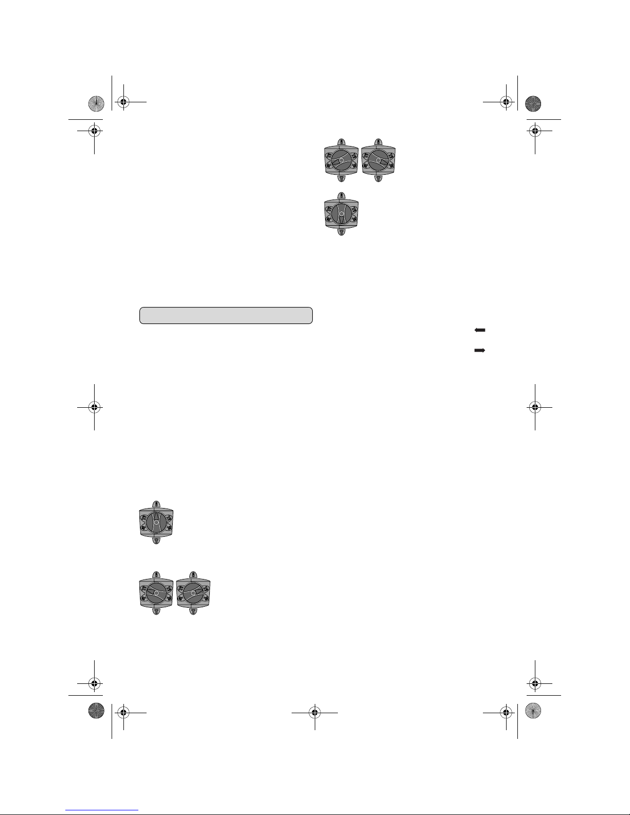
Français–27
18.8.08
Poussez le tuyau de guidage 20 du dispositif d’aspiration dans sa fixation de manière à ce que la tête
du dispositif d’aspiration soit posée sur la surface à
percer. Ne poussez pas le tuyau de guidage 20 plus
que nécessaire par dessus la tige télescopique 18,
de manière à ce que la plus grande partie possible
de la graduation sur la tige télescopique 18 reste
visible.
Resserrez fermement la vis papillon 19. Dévissez la
vis de serrage 16 de la butée de profondeur du dispositif d’aspiration.
Poussez la butée de profondeur 17 sur le tube télescopique 18 de manière à ce que l’écart X montré
sur la figure corresponde à la profondeur de perçage souhaitée.
Resserrez fermement la borne à vis 16 dans cette
position.
Mise en service
❏ Tenez compte de la tension du réseau ! La
tension de la source de courant doit coïncider avec les indications se trouvant sur
la plaque signalétique de l’outil électroportatif. Les outils électroportatifs marqués 230 V peuvent également être mis
en service sous 220 V.
Régler le mode de service
Au moyen du stop de rotation/de frappe 5, sélectionnez le mode d’exploitation souhaité de l’outil
électroportatif.
☞
Note : Ne changez le mode d’exploitation
que quand l’outil électroportatif est éteint !
Sinon, l’outil électroportatif pourrait être
endommagé.
Tournez le stop de rotation/de frappe 5 pour le mettre dans la position souhaitée.
Régler le sens de rotation
❏ N’actionnez le commutateur du sens de
rotation 8 qu’à l’arrêt total de l’appareil
électroportatif.
A l’aide du commutateur du sens de rotation 8, il est
possible de modifier le sens de rotation de l’outil
électroportatif.
Rotation à droite : Tourner le commutateur du
sens de rotation 8 jusqu’à butée en position .
Rotation à gauche : Tourner le commutateur du
sens de rotation 8 jusqu’à butée en position .
Mettez toujours le sens de rotation sur la droite pour
le perçage en frappe, le perçage et le burinage.
Mise en Marche/Arrêt
Pour mettre l’outil électroportatif en marche,
appuyer sur l’interrupteur Marche/Arrêt 7 et le
maintenir vous appuyez.
Pour arrêter l’outil électroportatif vous relâchez
l’interrupteur Marche/Arrêt 7.
Si la température de l’air est très basse, l’appareil
n’atteint sa pleine puissance de percussion/capacité
de frappe qu’au bout d’un certain temps.
Réglage de la vitesse de rotation/de la fréquence de frappe
Vous pouvez régler en continu le nombre de
tours/de coups pendant que l’outil électroportatif est
en marche, en appuyant plus ou moins sur l’interrupteur de Marche/Arrêt 7.
Une légère pression sur l’interrupteur Marche/
Arrêt 7 entraîne un vitesse de rotation/une fréquence de frappe basse. Plus la pression augmente,
plus la vitesse de rotation/la fréquence de frappe est
élevée.
Accouplement de surcharge
❏ Dès que l’outil de travail se coince ou qu’il
s’accroche, l’entraînement de la broche
de perçage est interrompu. En raison des
forces pouvant en résulter, tenez toujours
bien l’outil électroportatif des deux mains
et veiller à garder une position stable et
équilibrée.
Position pour le perçage
sans frappe du bois, du
métal, de la céramique ou de
matières plastiques ainsi que
pour le vissage et le taraudage
Position pour le perçage en
frappe dans le béton et
dans la pierre naturelle
Au cas où l’outil de travail ne
tournerait pas immédiatement après la mise en marche de l’outil électroportatif,
faites tourner lentement ce
dernier jusqu’à ce que l’outil
de travail tourne avec.
Position pour changer la
position du burin
Position pour le burinage
OBJ_BUCH-820-001.book Page 27 Monday, August 18, 2008 10:25 AM
Page 28
28–Français
18.8.08
❏ Arrêtez immédiatement l’outil électropor-
tatif et débloquer l’outil de travail lorsque
l’appareil électroportatif coince.
Lorsqu’on met l’appareil en marche,
l’outil de travail étant bloqué, il peut y
avoir de fortes réactions.
Changer la position du burin
Il est possible d’arrêter le burin dans 12 positions.
Ceci permet de se mettre dans la position de travail
optimale souhaitée.
Montez le burin dans le porte-outil.
Tournez le stop de rotation/de frappe 5 pour le met-
tre dans la position « changement de la position du
burin » (voir « Régler le mode de service », page 27).
Tournez le porte-outil dans la position du burin souhaitée.
Tournez le stop de rotation/de frappe 5 pour le met-
tre dans la position « burinage ». Le porte-outil est
ainsi arrêté.
Mettez le sens de rotation sur la droite pour le burinage.
Nettoyage et entretien
❏ Avant d’effectuer des travaux sur l’outil
électroportatif, retirez la fiche de la prise
de courant.
❏ Tenez toujours propres l’outil électropor-
tatif ainsi que les ouïes de ventilation afin
d’obtenir un travail impeccable et sûr.
❏ Remplacez immédiatement un capuchon
anti-poussière endommagé. Il est recommandé de faire effectuer ce travail par un
service après-vente.
Si, malgré tous les soins apportés à la fabrication et
au contrôle de l’outil électroportatif, celui-ci présentait un défaut, la réparation ne doit être confiée qu’à
un master-Service Würth.
Pour toute demande de renseignement ou commande de pièces de rechange, nous préciser impérativement le numéro d’article de l’outil
électroportatif indiqué sur la plaque signalétique.
La liste actuelle des pièces de rechange de cet outil
électroportatif peut être consultée sous
« http://www.wuerth.com/partsmanager »
ou demandée auprès de la succursale Würth la plus
proche.
Garantie légale
Cet outil électroportatif Würth est légalement
garanti, à partir de la date d’achat, conformément
aux dispositions légales/nationales (contre preuve
d’achat, facture ou bordereau de livraison). Une
livraison de remplacement ou une réparation est
assurée en cas de dommages sur l’appareil.
Les dommages résultant d’une usure naturelle, surcharge ou utilisation non conforme ne sont pas couverts par la garantie.
Les réclamations ne peuvent être reconnues que si
vous retournez l’outil électroportatif non démonté à
une succursale Würth, à votre vendeur Würth ou que
vous le transmettiez à un service après-vente autorisé pour outils électriques Würth.
Elimination des déchets
Les outils électroportatifs, ainsi que leurs accessoires
et emballages, doivent pouvoir suivre chacun une
voie de recyclage appropriée.
Seulement pour les pays de l’Union
Européenne :
Ne pas jeter votre appareil électroportatif
dans les ordures ménagères !
Conformément à la directive européenne
2002/96/CE relative aux déchets d’équi-
pements électriques et électroniques et sa
réalisation dans les lois nationales, les outils électroportatifs dont on ne peut plus se servir doivent être
séparés et suivre une voie de recyclage appropriée.
Sous réserve de modifications.
OBJ_BUCH-820-001.book Page 28 Monday, August 18, 2008 10:25 AM
Page 29
Español–29
18.8.08
Para su seguridad
Lea íntegramente estas advertencias de peligro e instrucciones.
En caso de no atenerse a las advertencias de peligro e instrucciones siguientes, ello puede ocasionar una descarga
eléctrica, un incendio y/o lesión grave.
❏ Instrucciones de seguridad adicionales,
ver suplemento.
❏ Utilice unos protectores auditivos. El ruido
intenso puede provocar sordera.
❏ Emplee las empuñaduras adicionales
suministradas con la herramienta eléctrica. La pérdida de control sobre la herra-
mienta eléctrica puede provocar un accidente.
❏ Utilice unos aparatos de exploración ade-
cuados para detectar posibles tuberías de
agua y gas o cables eléctricos ocultos, o
consulte a la compañía local que le abastece con energía. El contacto con cables eléc-
tricos puede electrocutarle o causar un incendio.
Al dañar las tuberías de gas, ello puede dar
lugar a una explosión. La perforación de una
tubería de agua puede redundar en daños materiales o provocar una electrocución.
❏ Únicamente sujete el aparato por las
empuñaduras aisladas al realizar trabajos en los que el útil pueda tocar conductores eléctricos ocultos o el propio cable
del aparato. El contacto con conductores por-
tadores de tensión puede hacer que las partes
metálicas del aparato le provoquen una descarga eléctrica.
❏ Trabajar sobre una base firme sujetando
la herramienta eléctrica con ambas
manos. La herramienta eléctrica es guiada de
forma más segura con ambas manos.
❏ Asegure la pieza de trabajo. Una pieza de
trabajo fijada con unos dispositivos de sujeción,
o en un tornillo de banco, se mantiene sujeta de
forma mucho más segura que con la mano.
❏ No trabaje materiales que contengan
amianto. El amianto es cancerígeno.
❏ Tome unas medidas de protección ade-
cuadas si al trabajar pudiera generarse
polvo combustible, explosivo, o nocivo
para la salud. Por ejemplo: ciertos tipos de
polvo son cancerígenos. Colóquese una mascarilla antipolvo y, si su aparato viene equipado
con la conexión correspondiente, utilice además
un equipo de aspiración adecuado.
❏ Mantenga limpio su puesto de trabajo. La
mezcla de diversos materiales es especialmente
peligrosa. Las aleaciones ligeras en polvo pueden arder o explotar.
❏ Antes de depositarla, esperar a que se
haya detenido la herramienta eléctrica. El
útil puede engancharse y hacerle perder el control sobre la herramienta eléctrica.
❏ No utilice la herramienta eléctrica si el
cable está dañado. No toque un cable
dañado, y desconecte el enchufe de la
red, si el cable se daña durante el trabajo.
Un cable dañado comporta un mayor riesgo de
electrocución.
❏ Solamente utilice accesorios originales
Würth.
Utilización reglamentaria
La herramienta eléctrica ha sido diseñada para taladrar con percusión en hormigón, ladrillo y piedra, y
para realizar trabajos ligeros de cincelado. También
es apropiada para taladrar sin percutir en madera,
metal, cerámica y plástico.
La responsabilidad por daños derivados de una utilización no reglamentaria corre a cargo del usuario.
Elementos del aparato
Despliegue y mantenga abierta la solapa con la
imagen del aparato mientras lee las instrucciones de
manejo.
La numeración de los elementos del aparato está
referida a la imagen de la herramienta eléctrica en
la página ilustrada.
1 Portaútiles SDS-plus
2 Caperuza antipolvo
3 Casquillo de enclavamiento
4 Anillo de enclavamiento de portaútiles
5 Mando desactivador de percusión y giro
6 Amortiguador de vibraciones
7 Interruptor de conexión/desconexión
8 Selector de sentido de giro
OBJ_BUCH-820-001.book Page 29 Monday, August 18, 2008 10:25 AM
Page 30
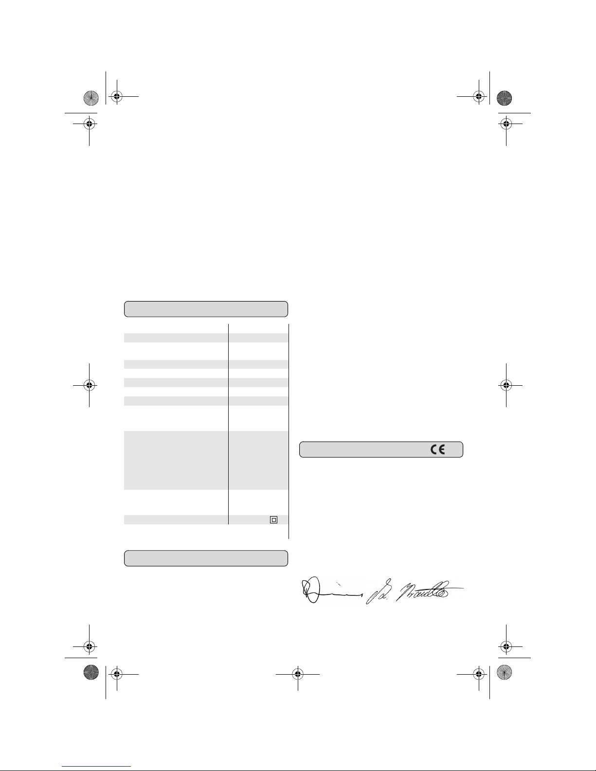
30– Español
18.8.08
9 Botón de ajuste del tope de profundidad
10 Empuñadura adicional
11 Tope de profundidad
12 Portabrocas intercambiable de cierre rápido*
13 Casquillo delantero del portabrocas intercam-
biable de cierre rápido*
14 Anillo de retención del portabrocas intercam-
biable de cierre rápido*
15 Boquilla de aspiración del dispositivo de aspira-
ción*
16 Tornillo de fijación del dispositivo de aspiración*
17 Tope de profundidad del dispositivo de aspira-
ción*
18 Tubo telescópico del dispositivo de aspiración*
19 Tornillo de mariposa del dispositivo de aspira-
ción*
20 Tubo de guía del dispositivo de aspiración*
Los accesorios descritos e ilustrados no corresponden al material que se adjunta de serie.
Datos técnicos
Información sobre ruidos y vibraciones
Determinación de los valores de medición según
EN 60745.
El nivel de presión sonora típico del aparato, determinado con un filtro A, asciende a: Nivel de presión
sonora 93 dB(A); nivel de potencia acústica
104 dB(A). Tolerancia K=2 dB.
¡Colocarse un protector de oídos!
Nivel total de vibraciones (suma vectorial de tres
direcciones) determinado según EN 60745:
Taladrado con percusión en hormigón: Valor de
vibraciones generadas a
h
=8 m/s2, tolerancia
K= 1,5 m/s
2
,
Cincelar: Valor de vibraciones generadas
a
h
=7 m/s2, tolerancia K=1,5 m/s2.
El nivel de vibraciones indicado en estas instrucciones ha sido determinado según el procedimiento de
medición fijado en la norma EN 60745 y puede servir como base de comparación con otras herramientas eléctricas. También es adecuado para
estimar provisionalmente la solicitación experimentada por las vibraciones.
El nivel de vibraciones indicado ha sido determinado para las aplicaciones principales de la herramienta eléctrica. Por ello, el nivel de vibraciones
puede ser diferente si la herramienta eléctrica se utiliza para otras aplicaciones, con útiles diferentes, o
si el mantenimiento de la misma fuese deficiente.
Ello puede suponer un aumento drástico de la solicitación por vibraciones durante el tiempo total de
trabajo.
Para determinar con exactitud la solicitación experimentada por las vibraciones, es necesario considerar también aquellos tiempos en los que el aparato
esté desconectado, o bien, esté en funcionamiento,
pero sin ser utilizado realmente. Ello puede suponer
una disminución drástica de la solicitación por
vibraciones durante el tiempo total de trabajo.
Fije unas medidas de seguridad adicionales para
proteger al usuario de los efectos por vibraciones,
como por ejemplo: Mantenimiento de la herramienta eléctrica y de los útiles, conservar calientes
las manos, organización de las secuencias de trabajo.
Declaración de conformidad
Declaramos bajo nuestra responsabilidad, que el
producto descrito bajo “Datos técnicos” está en conformidad con las normas o documentos normalizados siguientes: EN 60745 de acuerdo con las
regulaciones 2004/108/CE, 98/37/CE (hasta el
28.12.2009), 2006/42/CE (a partir del
29.12.2009).
Expediente técnico en:
Adolf Würth GmbH & Co.KG, PFW,
D-74650 Künzelsau
Künzelsau, a 09.07.2008
Adolf Würth GmbH & Co. KG
Martillo perforador BMH 32-XE
Nº de art. 0702 543 X
Potencia absorbida
nominal W 900
Revoluciones nominales min
-1
0– 760
Frecuencia de percusión min
-1
0– 3 600
Energía por percusión J 5,0
Posiciones del cincel 12
Alojamiento del útil SDS-plus
Lubricación Lubricación
permanente
centralizada
Ø máx. de perforación
– Hormigón (con broca
helicoidal)
– Ladrillo (con corona
perforadora hueca)
–Acero
–Madera
mm
mm
mm
mm
32
90
13
32
Peso según
EPTA-Procedure
01/2003 kg 4,7
Clase de protección /II
Estos datos son válidos para tensiones nominales de [U]
230/240 V.
P. Zürn A. Kräutle
OBJ_BUCH-820-001.book Page 30 Monday, August 18, 2008 10:25 AM
Page 31

Español–31
18.8.08
Empuñadura adicional
❏ Antes de cualquier manipulación en la
herramienta eléctrica, sacar el enchufe de
red de la toma de corriente.
❏ Solamente utilice la herramienta eléctrica
con la empuñadura adicional 10 montada.
La empuñadura adicional 10 puede girarse a cualquier posición para permitirle trabajar manteniendo
una postura firme y cómoda.
Afloje en sentido contrario a las agujas del reloj el
mango de la empuñadura adicional 10 y gire ésta
a la posición deseada. Seguidamente, apriete el
mango en el sentido de las agujas del reloj para
sujetar la empuñadura adicional 10.
Ajuste de la profundidad de perforación (ver figura A)
El tope de profundidad 11 permite ajustar la profundidad de perforación X deseada.
Presione el botón de ajuste del tope de profundidad
9 e introduzca el tope de profundidad en la empuñadura adicional 10.
Inserte hasta el tope el útil SDS-plus en el portaútiles
SDS-plus 1. De no proceder así, el ajuste de la profundidad de perforación es incorrecto debido a la
movilidad que tiene el útil SDS-plus.
Saque el tope de profundidad de manera que la
medida entre la puntas de la broca y del tope de
profundidad corresponda a la profundidad de perforación X.
La cara estriada del tope de profundidad 11 deberá
quedar hacia abajo.
Selección del portaútiles
Para taladrar con percusión se precisan útiles SDS
plus en combinación con el portaútiles SDS plus 1.
Para taladrar sin percusión en madera, metal, cerámica y plástico, así como para atornillar y hacer roscas se utilizan útiles sin vástago SDS-plus (p. ej.
brocas de vástago cilíndrico). Para estos útiles se
precisa un portabrocas de sujeción rápida.
☞
Observación: ¡No utilice útiles sin SDS-plus
ni para taladrar con percusión ni para cincelar! Al taladrar con percusión o cincelar ello
perjudicaría a los útiles sin SDS-plus y al portabrocas.
El portaútiles SDS plus 1 puede ser sustituido fácilmente por el portabrocas intercambiable de cierre
rápido 12.
Cambio del portaútiles
Desmontaje del portaútiles SDS plus
o del portabrocas intercambiable
de cierre rápido (ver figura B)
Empuje firmemente, en dirección de la flecha, el
anillo de enclavamiento del portaútiles 4, manténgalo en esa posición, y retire hacia delante el portaútiles 1 o el portabrocas intercambiable de cierre
rápido 12.
Una vez desmontado, proteja de la suciedad el portaútiles 1 o portabrocas intercambiable de cierre
rápido 12. Si fuese preciso, lubrique levemente el
dentado de arrastre.
Montaje del portaútiles SDS plus o
del portabrocas intercambiable de
cierre rápido
Sujete el portaútiles 1 o portabrocas intercambiable
de cierre rápido 12 abarcándolo con toda la mano.
Inserte girándolo el portaútiles 1 o portabrocas
intercambiable de cierre rápido 12 en el alojamiento del portabrocas hasta percibir claramente su
enclavamiento.
El portaútiles 1 o portabrocas intercambiable de cierre rápido 12 se enclava automáticamente. Tire del
portaútiles para asegurarse de que ha quedado
correctamente sujeto.
Cambio de útil
El portaútiles SDS plus le permite cambiar el útil de
forma sencilla y cómoda sin precisar para ello una
herramienta.
Condicionado por el sistema, el útil SDS-plus puede
moverse libremente. A ello se debe que se presente
un error de redondez al girar en vacío. Esto no
afecta para nada a la precisión del taladro realizado, ya que la broca se autocentra al taladrar.
La caperuza antipolvo 2 evita en gran medida que
el polvo que se va produciendo al trabajar no logre
penetrar en el portaútiles. Al montar el útil, preste
atención a no dañar la caperuza antipolvo 2.
❏ Haga sustituir de inmediato una caperuza
antipolvo deteriorada. Se recomienda
que este trabajo sea realizado por un servicio técnico.
OBJ_BUCH-820-001.book Page 31 Monday, August 18, 2008 10:25 AM
Page 32

32– Español
18.8.08
Montaje del útil SDS-plus
(ver figura C)
Limpie primero y aplique a continuación una capa
ligera de grasa al extremo de inserción del útil.
Inserte girando el útil en el portaútiles hasta conseguir que éste quede sujeto automáticamente.
Tire del útil para cerciorarse de que ha quedado
correctamente sujeto.
Desmontaje del útil SDS-plus
(ver figura D)
Empuje hacia atrás el casquillo de enclavamiento 3
y retire el útil.
Aplicación de útiles sin SDS-plus
(ver figura E)
☞
Observación: ¡No utilice útiles sin SDS-plus
ni para taladrar con percusión ni para cincelar! Al taladrar con percusión o cincelar ello
perjudicaría a los útiles sin SDS-plus y al portabrocas.
Monte el portabrocas intercambiable de cierre
rápido 12.
Sujete firmemente el anillo de retención del portabrocas intercambiable de cierre rápido 12. Abra
el portaútiles girando el casquillo anterior en dirección al símbolo “ ”.
Inserte el útil en el portabrocas intercambiable de
cierre rápido 12. Sujete firmemente el anillo de
retención del portabrocas intercambiable de cierre
rápido 12 y gire el casquillo anterior en dirección al
símbolo “ ”.
Verifique la sujeción firme del útil tirando del mismo.
☞
Observación: En caso de haber abierto
hasta el tope el portabrocas, puede ocurrir
que al intentar cerrar éste se perciba un ruido
de carraca y que no se consiga cerrar el portabrocas.
En este caso, gire una vez el casquillo anterior
13 en sentido contrario a la dirección de la
flecha. A continuación es posible cerrar el
portaútiles.
Gire el mando desactivador de percusión y giro 5 a
la posición “Taladrar”.
Desmontaje de útiles sin SDS-plus
(ver figura E)
Sujete firmemente el anillo de retención del portabrocas intercambiable de cierre rápido 12. Abra
el portaútiles girando el casquillo anterior en dirección al símbolo “ ”.
Retire el útil.
Aspiración de polvo con el dispositivo de
aspiración (accesorio especial)
Montaje del dispositivo de aspiración (ver figura F)
Para aspirar el polvo se requiere un dispositivo de
aspiración de polvo (accesorio opcional). Al taladrar, el dispositivo de aspiración es presionado continuamente contra la base por la fuerza de un
resorte, consiguiéndose así que éste asiente continuamente contra la misma.
Pulse el botón de ajuste del tope de profundidad 9 y
retire el tope de profundidad 11. Vuelva a presionar
la tecla 9 y monte por el frente el dispositivo de aspiración en la empuñadura adicional 10.
Conecte una manguera a la boquilla de aspiración
15 del dispositivo de aspiración.
El aspirador debe ser adecuado para el material a
trabajar.
Para aspirar polvo especialmente nocivo para la
salud, cancerígeno, o polvo seco utilice un aspirador especial.
Ajuste de la profundidad de perforación en el dispositivo de aspiración (ver figura G)
Ud. puede fijar también la profundidad de perforación X deseada estando montado el dispositivo de
aspiración.
Inserte hasta el tope el útil SDS-plus en el portaútiles
SDS-plus 1. De no proceder así, el ajuste de la profundidad de perforación es incorrecto debido a la
movilidad que tiene el útil SDS-plus.
Afloje el tornillo de mariposa 19 del dispositivo de
aspiración.
Asiente firmemente el útil, estando éste detenido,
contra el punto a taladrar. Al realizar esto, el útil
SDS-plus deberá asentar contra la superficie.
Desplace el tubo de guía 20 del dispositivo de aspiración en el soporte, de forma que el cabezal del
dispositivo de aspiración asiente contra la superficie
a taladrar. No desplace el tubo de guía 20 más de
lo necesario sobre el tubo telescópico 18 con el fin
de que sea visible la mayor parte posible de la
escala del tubo telescópico 18.
Apriete nuevamente el tornillo de mariposa 19.
Afloje el tornillo de fijación 16 del tope de profundidad del dispositivo de aspiración.
Desplace el tope de profundidad 17 sobre el tubo
telescópico 18 de manera que la distancia X mostrada en la figura corresponda a la profundidad de
perforación deseada.
Apriete el tornillo de fijación 16 en esa posición.
OBJ_BUCH-820-001.book Page 32 Monday, August 18, 2008 10:25 AM
Page 33

Español–33
18.8.08
Puesta en marcha
❏ ¡Observe la tensión de red! La tensión de
la fuente de energía deberá coincidir con
las indicaciones en la placa de características de la herramienta eléctrica. Las
herramientas eléctricas marcadas con
230 V pueden funcionar también a 220 V.
Ajuste del modo de operación
Con el mando desactivador de percusión y giro 5
puede Ud. ajustar el modo de operación de la
herramienta eléctrica.
☞
Observación: ¡Únicamente cambie el modo
de operación estando desconectada la herramienta eléctrica! En caso contrario podría
dañarse la herramienta eléctrica.
Gire el mando desactivador de percusión y giro 5 a
la posición deseada.
Ajuste del sentido de giro
❏ Solamente accione el selector de sentido
de giro 8 con la herramienta eléctrica
detenida.
El selector de sentido de giro 8 le permite modificar
el sentido de giro de la herramienta eléctrica.
Giro a derechas: Gire hasta el tope el selector de
sentido de giro 8 a la posición .
Giro a izquierdas: Gire hasta el tope el selector
de sentido de giro 8 a la posición .
Al taladrar con o sin percusión, y al cincelar, ajuste
siempre el sentido de giro a derechas.
Conexión/desconexión
Para la puesta en marcha de la herramienta eléctrica accionar y mantener en esa posición el interruptor de conexión/desconexión 7.
Para desconectar la herramienta eléctrica soltar el
interruptor de conexión/desconexión 7.
A bajas temperaturas, la herramienta eléctrica
deberá funcionar primero durante cierto tiempo
hasta que alcance su pleno rendimiento de percusión/impacto.
Ajuste del nº de revoluciones/frecuencia de percusión
Variando la presión ejercida sobre el interruptor de
conexión/desconexión 7 puede Ud. regular de
forma continua las revoluciones/nº de impactos de
la herramienta eléctrica.
Accionando ligeramente el interruptor de conexión/
desconexión 7 se obtienen unas revoluciones/frecuencia de percusión reducida. Aumentando paulatinamente la presión se van aumentando en igual
medida las revoluciones/frecuencia de percusión.
Embrague limitador de par
❏ En caso de engancharse o bloquearse el
útil se desacopla el husillo de la unidad de
accionamiento. Debido a la elevada
fuerza de reacción resultante, siempre
sujete la herramienta eléctrica con ambas
manos y trabaje sobre una base firme.
❏ En caso de bloquearse el útil, desconectar
la herramienta eléctrica y liberar el útil. Si
el aparato se conecta estando bloqueado
el útil de taladrar se producen unos pares
de reacción muy elevados.
Modificación de la posición del cincel
El cincel puede sujetarse en 12 posiciones diferentes. Ello le permite adoptar en cada caso una posición de trabajo óptima.
Monte el cincel en el portaútiles.
Gire el mando desactivador de percusión y giro 5 a
la posición “Ajuste del cincel” (ver “Ajuste del modo
de operación”, página 33).
Gire el portaútiles hasta conseguir la posición del
cincel deseada.
Gire el mando desactivador de percusión y giro 5 a
la posición “Cincelar”. El portaútiles queda retenido
entonces en esa posición.
Para cincelar ajuste el sentido de giro a derechas.
Posición para Taladrar, sin
percutir, en madera, metal,
cerámica y plástico, así como
para atornillar y para hacer
roscas
Posición para Taladrar con
percusión en hormigón o
piedra
Si el útil no comienza a girar
inmediatamente nada más
conectar la herramienta
eléctrica, déjela funcionar a
bajas revoluciones hasta que
gire también el útil.
Posición para modificar la
posición del cincel
Posición para Cincelar
OBJ_BUCH-820-001.book Page 33 Monday, August 18, 2008 10:25 AM
Page 34

34– Español
18.8.08
Mantenimiento y limpieza
❏ Antes de cualquier manipulación en la
herramienta eléctrica, sacar el enchufe de
red de la toma de corriente.
❏ Mantenga limpia la herramienta eléctrica
y las rejillas de refrigeración para trabajar con eficacia y seguridad.
❏ Haga sustituir de inmediato una caperuza
antipolvo deteriorada. Se recomienda
que este trabajo sea realizado por un servicio técnico.
Si a pesar de los esmerados procesos de fabricación
y control, la herramienta eléctrica llegara a averiarse, la reparación deberá encargarse a un servicio técnico Würth master.
Para cualquier consulta o pedido de piezas de
repuesto es imprescindible indicar el nº de artículo
que figura en la placa de características de la herramienta eléctrica.
La lista de piezas de repuesto actual de esta herramienta eléctrica puede consultarse en internet bajo
“http://www.wuerth.com/partsmanager”
o solicitarse al establecimiento Würth más cercano.
Garantía
Para esta herramienta eléctrica Würth concedemos
una garantía a partir de la fecha de compra (comprobación mediante factura o albarán de entrega)
según las disposiciones legales específicas de cada
país. Los daños serán subsanados mediante reposición o reparación del aparato, según se estime conveniente.
No quedan cubiertos por la garantía los daños ocasionados por desgaste natural, sobrecarga o
manejo inadecuado.
Las reclamaciones solamente podrán tenerse en
cuenta si Ud. entrega la herramienta eléctrica, sin
desmontar, a un establecimiento Würth, al personal
del Servicio Exterior Técnico Würth, o a un servicio
técnico oficial para herramientas eléctricas Würth.
Eliminación
Recomendamos que las herramientas eléctricas,
accesorios y embalajes sean sometidos a un proceso de recuperación que respete el medio
ambiente.
Sólo para los países de la UE:
¡No arroje las herramientas eléctricas a
la basura!
Conforme a la Directriz Europea
2002/96/CE sobre aparatos eléctricos y
electrónicos inservibles, tras su transposición en ley nacional, deberán acumularse por separado las herramientas eléctricas para ser sometidas
a un reciclaje ecológico.
Reservado el derecho de modificación.
OBJ_BUCH-820-001.book Page 34 Monday, August 18, 2008 10:25 AM
Page 35

Português– 35
18.8.08
Para sua segurança
Devem ser lidas todas as indicações de advertência e todas as
instruções. O desrespeito das adver-
tências e instruções apresentadas
abaixo pode causar choque eléctrico,
incêndio e/ou graves lesões.
❏ Mais indicações de segurança encon-
tram-se no anexo.
❏ Usar protecção auricular. Ruídos podem
provocar a surdez.
❏ Utilizar os punhos adicionais fornecidos
com a ferramenta eléctrica. A perda de con-
trole pode provocar lesões.
❏ Utilizar detectores apropriados, para
encontrar cabos escondidos, ou consulte a
companhia eléctrica local. O contacto com
cabos eléctricos pode provocar fogo e choques
eléctricos. Danos em tubos de gás podem levar
à explosão. A penetração num cano de água
causa danos materiais ou pode provocar um
choque eléctrico.
❏ Ao executar trabalhos durante os quais
possam ser atingidos cabos eléctricos ou o
próprio cabo de rede, deverá sempre
segurar a ferramenta eléctrica pelas
superfícies isoladas do punho. O contacto
com um cabo sob tensão pode colocar peças de
metal da ferramenta eléctrica sob tensão e levar
a um choque eléctrico.
❏ Segurar a ferramenta eléctrica firme-
mente com ambas as mãos durante o trabalho e manter uma posição firme. A
ferramenta eléctrica é conduzida com segurança
com ambas as mãos.
❏ Fixar a peça a ser trabalhada. Uma peça a
ser trabalhada fixa com dispositivos de aperto ou
com torno de bancada está mais firme do que
segurada com a mão.
❏ Não processar material que contenha
asbesto. Asbesto é considerado como sendo
cancerígeno.
❏ Tomar medidas de protecção, se durante
o trabalho houver a possibilidade de
serem produzidos pós nocivos à saúde,
inflamáveis ou explosivos. Por exemplo:
Alguns pós são considerados como sendo cancerígenos. Usar uma máscara de protecção contra o pó e, se for possível, utilizar uma aspiração
de pó/aparas.
❏ Manter o seu local de trabalho limpo. Mis-
turas de material são especialmente perigosas.
Pó de metal leve pode queimar ou explodir.
❏ Espere a ferramenta eléctrica parar com-
pletamente, antes de depositá-la. A ferra-
menta de aplicação pode emperrar e levar à
perda de controlo sobre a ferramenta eléctrica.
❏ Não utilizar a ferramenta eléctrica com
um cabo danificado. Não tocar no cabo
danificado nem puxar a ficha da tomada,
se o cabo for danificado durante o trabalho. Cabos danificados aumentam o risco de
um choque eléctrico.
❏ Só utilizar acessórios originais Würth.
Utilização conforme as disposições
A ferramenta eléctrica é destinada para furar com
percussão em betão, tijolos e pedras, assim como
para cinzelar. Ela também é apropriada para furar
sem percussão em madeira, metal, cerâmica e plástico.
O utente é responsável por danos devido a utilização não conforme às disposições.
Elementos do aparelho
Abrir a página basculante contendo a apresentação
do aparelho, e deixar esta página aberta enquanto
estiver lendo a instrução de serviço.
A numeração dos elementos do aparelho refere-se
à apresentação da ferramenta eléctrica na página
de esquemas.
1 Fixação da ferramenta SDS-plus
2 Capa para protecção contra pó
3 Bucha de travamento
4 Anel de travamento da fixação da ferramenta
5 Comutador de percussão/paragem de rotação
6 Amortecimento de vibrações
7 Interruptor de ligar-desligar
8 Comutador do sentido de rotação
9 Tecla para ajuste do esbarro de profundidade
OBJ_BUCH-820-001.book Page 35 Monday, August 18, 2008 10:25 AM
Page 36

36– Português
18.8.08
10 Punho adicional
11 Esbarro de profundidade
12 Mandril de substituição de aperto rápido*
13 Luva dianteira do mandril de substituição de
aperto rápido*
14 Anel de fixação do mandril de substituição de
aperto rápido*
15 Abertura de aspiração, dispositivo de aspiração*
16 Parafuso de aperto, dispositivo de aspiração*
17 Limitador de profundidade, dispositivo de aspi-
ração*
18 Tubo telescópico, dispositivo de aspiração*
19 Parafuso de orelhas, dispositivo de aspiração*
20 Tubo de guia, dispositivo de aspiração*
Acessórios apresentados ou descritos não pertencem ao volume de fornecimento.
Dados técnicos
Informação sobre ruídos/vibrações
Valores de medição averiguados conforme
EN 60745.
O nível de ruído avaliado como A do aparelho é
tipicamente: Nível de pressão acústica 93 dB(A);
Nível de potência acústica 104 dB(A). Incerteza
K=2dB.
Usar protecção auricular!
Valores totais de vibração (soma dos vectores das
três direcções) determinados conforme EN 60745:
Furar com percussão em betão: Valor de emissão
de vibrações a
h
=8 m/s2, incerteza K=1,5 m/s2,
Cinzelar: Valor de emissão de vibrações
a
h
=7 m/s2, incerteza K=1,5 m/s2.
O nível de oscilações indicado nestas instruções de
serviço foi medido de acordo com um processo de
medição normalizado pela norma EN 60745 e
pode ser utilizado para a comparação de aparelhos. Ele também é apropriado para uma avaliação
provisória da carga de vibrações.
O nível de vibrações indicado representa as aplicações principais da ferramenta eléctrica. Se a ferramenta eléctrica for utilizada para outras aplicações,
com outras ferramentas de trabalho ou com manutenção insuficiente, é possível que o nível de vibrações seja diferente. Isto pode aumentar
sensivelmente a carga de vibrações para o período
completo de trabalho.
Para uma estimação exacta da carga de vibrações,
também deveriam ser considerados os períodos nos
quais o aparelho está desligado ou funciona, mas
não está sendo utilizado. Isto pode reduzir a carga
de vibrações durante o completo período de trabalho.
Além disso também deverão ser estipuladas medidas de segurança para proteger o operador contra
o efeito de vibrações, como por exemplo: Manutenção de ferramentas eléctricas e de ferramentas de
trabalho, manter as mãos quentes e organização
dos processos de trabalho.
Declaração de conformidade
Declaramos sob nossa exclusiva responsabilidade
que o produto descrito em “Dados técnicos” cumpre
as seguintes normas ou documentos normativos:
EN 60745 conforme as disposições das directivas
2004/108/CE, 98/37/CE (até 28.12.2009),
2006/42/CE (a partir de 29.12.2009).
Processo técnico em:
Adolf Würth GmbH & Co.KG, PFW,
D-74650 Künzelsau
Künzelsau, 09.07.2008
Adolf Würth GmbH & Co. KG
Martelo perfurador BMH 32-XE
N° do artigo 0702 543 X
Potência nominal
consumida W 900
Número de rotações
nominal
min
-1
0– 760
N° de percussões min
-1
0– 3 600
Força de impactos
individuais
J 5,0
Ajustes para cinzelar 12
Fixação da ferramenta SDS-plus
Lubrificação Lubrificação cen-
tral permanente
máx. Ø de perfuração
– Betão (com brocas
helicoidais)
– Alvenaria (com brocas
de coroa oca)
–Aço
–Madeira
mm
mm
mm
mm
32
90
13
32
Peso conforme EPTAProcedure 01/2003 kg 4,7
Classe de protecção /II
As indicações valem para tensões nominais [U]
230/240 V.
P. Zürn A. Kräutle
OBJ_BUCH-820-001.book Page 36 Monday, August 18, 2008 10:25 AM
Page 37

Português– 37
18.8.08
Punho adicional
❏ Antes de todos trabalhos na ferramenta
eléctrica deverá puxar a ficha de rede da
tomada.
❏ Só utilizar a sua ferramenta eléctrica com
o punho adicional 10.
O punho adicional 10 pode ser movimentado como
desejar, para alcançar uma posição de trabalho
segura e livre de fadiga.
Girar a parte inferior do punho adicional 10 no sentido contrário dos ponteiros do relógio e deslocar o
punho adicional 10 para a posição desejada. Em
seguida girar a parte inferior do punho adicional 10
no sentido dos ponteiros do relógio para reapertar.
Ajustar a profundidade de perfuração (vejafiguraA)
Com o esbarro de profundidade 11 é possível
determinar a profundidade de perfuração X desejada.
Pressionar a tecla para o ajuste do esbarro de profundidade 9 e colocar o esbarro de profundidade
no punho adicional 10.
Introduzir a ferramenta de trabalho SDS-plus completamente na fixação da ferramenta SDS-plus 1.
Caso contrário a mobilidade da ferramenta SDSplus pode levar a um ajuste incorrecto da profundidade de perfuração.
Puxar o esbarro de profundidade para fora, de
modo que a distância entre a ponta da broca e a
ponta do esbarro de profundidade corresponda à
profundidade de perfuração desejada X.
O estriamento no esbarro de profundidade 11 deve
mostrar para baixo.
Seleccionar a fixação da ferramenta
Para furar com percussão são necessárias ferramentas SDS-plus, que são encaixadas na fixação de
ferramenta SDS-plus 1.
Para furar, sem percussão, em madeira, metal,
cerâmica e plástico, assim como para furar e para
cortar roscas são usadas ferramentas sem SDS-plus
(p. ex. brocas com encabadouro cilíndrico). Para
estas ferramentas são necessários um mandril de
brocas de aperto rápido.
☞
Nota: Não utilizar ferramentas sem SDS-plus
para furar com percussão ou para cinzelar!
Ferramentas sem SDS-plus e o seus mandris
de broca são danificados ao furar com percussão ou ao cinzelar.
A fixação de ferramentas SDS-plus 1 pode ser facilmente substituída pelo mandril de substituição de
aperto rápido 12.
Substituir a admissão da ferramenta
Desmontar a fixação de ferramentas SDS-plus ou o mandril de substiuição de aperto rápido
(veja figura B)
Apertar o anel de travamento da fixação da ferramenta 4 firmemente no sentido da seta, segurar
nesta posição e retirar a fixação da ferramenta 1 ou
o mandril de substituição de aperto rápido 12
puxando pela frente.
Proteger a fixação da ferramenta 1 ou o mandril de
substituição de aperto rápido 12 contra sujidade
após retirar. Lubrificar os dentes de arrastamento
sempre que necessário.
Montar a fixação de ferramenta ou
o mandril de substiuição de aperto
rápido
Segurar a fixação da ferramenta 1 ou o mandril de
substituição de aperto rápido 12 com a mão toda.
Introduzir a fixação da ferramenta 1 ou o mandril
de substituição de aperto rápido 12 na fixação do
mandril de brocas, girando, até ouvir um nítido
ruído de engate.
A fixação da ferramenta 1 ou o mandril de substituição de aperto rápido 12 travam automaticamente.
Puxar a fixação da ferramenta para controlar o travamento.
Troca de ferramenta
Com a fixação de ferramenta SDS-plus é possível
trocar fácil e confortavelmente as ferramentas de
trabalho, sem ter que utilizar ferramentas.
O sistema prevê que a ferramenta de trabalho SDSplus possa se movimentar livremente. Com isto há
uma excentricidade na marcha em vazio. Esta
excentricidade não tem qualquer efeito sobre a
exactidão do orifício, porque a broca é automaticamente centrada durante a perfuração.
A capa de protecção contra pó 2 evita, consideravelmente, que penetre pó de perfuração no encabadouro durante o funcionamento. Ao introduzir a
ferramenta deverá assegurar-se de que a capa de
protecção contra pó 2 não seja danificada.
❏ Uma capa de protecção contra pó deve
ser substituida imediatamente. Recomendamos que esta tarefa seja efectuada por
uma oficina de serviço pós-venda.
OBJ_BUCH-820-001.book Page 37 Monday, August 18, 2008 10:25 AM
Page 38

38– Português
18.8.08
Introduzir a ferramenta de trabalho
SDS-plus (veja figura C)
Limpar a extremidade de encaixe da ferramenta de
trabalho e lubrificá-la levemente.
Introduzir a ferramenta de trabalho no encabadouro, girando até travar-se automaticamente.
Puxar a ferramenta para controlar o travamento.
Retirar a ferramenta de trabalho
SDS-plus (veja figura D)
Empurrar a bucha de travamento 3 para trás e retirar a ferramenta de trabalho.
Introduzir ferramentas de trabalho
sem SDS-plus (veja figura E)
☞
Nota: Não utilizar ferramentas sem SDS-plus
para furar com percussão ou para cinzelar!
Ferramentas sem SDS-plus e o seus mandris
de broca são danificados ao furar com per-
cussão ou ao cinzelar.
Introduzir o mandril de brocas de aperto rápido 12.
Segurar o anel de fixação do mandril de brocas de
aperto rápido 12. Abrir a fixação da ferramenta
girando a luva dianteira no sentido do símbolo
“”.
Introduzir a ferramenta de trabalho no mandril de
brocas de aperto rápido 12. Segurar o anel de fixação do mandril de brocas de aperto rápido 12 e
girar a luva dianteira no sentido do símbolo
“”.
Puxar a ferramenta para verificar se está firme.
☞
Nota: Se a fixação da ferramenta estiver
completamente aberta, é possível que ao
fechar a fixação da ferramenta seja escutado
o ruído de engate, mas que a fixação da fer-
ramenta não se feche.
Neste caso, a bucha dianteira 13 deve ser
girada uma vez no sentido contrário da seta.
Em seguida será possível fechar a fixação da
ferramenta.
Girar o interruptor de percussão/paragem de rota-
ção 5 para a posição “Furar”.
Retirar ferramentas de trabalho
sem SDS-plus (veja figura E)
Segurar o anel de fixação do mandril de brocas de
aperto rápido 12. Abrir a fixação da ferramenta
girando a luva dianteira no sentido do símbolo
“”.
Retirar a ferramenta de trabalho.
Aspiração de pó com o dispositivo de aspi-
ração (acessório)
Montar o dispositivo de aspiração
(vejafiguraF)
Para a aspiração de pó é necessário um dispositivo
de aspiração (acessório). Ao furar, o dispositivo de
aspiração é retraído por uma mola, de modo que a
ponta do dispositivo de aspiração é mantida sempre
rente à superfície.
Premir a tecla para o ajuste do limitador de profundidade 9 e retirar o limitador de profundidade 11.
Premir novamente a tecla 9 e colocar o dispositivo
de aspiração, pela frente, no punho adicional 10.
Conectar uma mangueira de aspiração à abertura
de aspiração 15 do dispositivo de aspiração.
O aspirador de pó deve ser apropriado para o
material a ser trabalhado.
Utilizar um aspirador especial para aspirar pó que
seja extremamente nocivo à saúde, cancerígeno ou
seco.
Ajustar a profundidade de perfuração no dispositivo de aspiração
(vejafiguraG)
A profundidade de perfuração X desejada, também
pode ser determinada com o dispositivo de aspiração montado.
Introduzir a ferramenta de trabalho SDS-plus completamente na fixação da ferramenta SDS-plus 1.
Caso contrário a mobilidade da ferramenta SDSplus pode levar a um ajuste incorrecto da profundidade de perfuração.
Soltar o parafuso de orelhas 19 do dispositivo de
aspiração.
Apoiar a ferramenta eléctrica, desligada, firmemente sobre o local a ser furado. A ferramenta de
trabalho SDS-plus deve estar apoiada sobre a
superfície.
Deslocar o tubo de guia 20 do dispositivo de aspiração em seu dispositivo de fixação, de modo que a
ponta do dispositivo de aspiração esteja apoiada
sobre a superfície a ser furada. Não deslocar o tubo
de guia 20 mais do que necessário sobre o tubo
telescópico 18, de modo que a maior parte possível
da escala do tubo telescópico 18 permaneça visível.
Reapertar a porca de orelhas 19. Soltar o parafuso
de aperto 16 no limitador de profundidade do dispositivo de aspiração.
Deslocar o limitador de profundidade 17 sobre o
tubo telescópico 18, de modo que a distância X,
indicada na figura, corresponda à profundidade de
perfuração desejada.
Apertar o parafuso de aperto 16 nesta posição.
OBJ_BUCH-820-001.book Page 38 Monday, August 18, 2008 10:25 AM
Page 39

Português– 39
18.8.08
Colocação em funcionamento
❏ Observar a tensão de rede! A tensão da
fonte de corrente deve coincidir com a
indicada na chapa de identificação da ferramenta eléctrica. Ferramentas eléctricas
marcadas para 230 V também podem ser
operadas com 220 V.
Ajustar o tipo de funcionamento
Com o interruptor de percussão/paragem de rotação 5 é possível seleccionar o tipo de funcionamento.
☞
Nota: Só mudar de tipo de funcionamento
com a ferramenta eléctrica desligada! Caso
contrário, é possível que a ferramenta eléctrica seja danificada.
Girar o interruptor de percussão/paragem de rotação 5 para a posição desejada.
Ajustar o sentido de rotação
❏ Só accionar o comutador de sentido de
rotação 8 com a ferramenta eléctrica
parada.
Com o comutador do sentido de rotação 8 é possível mudar o sentido de rotação da ferramenta eléctrica.
Rotação à direita: Girar o comutador do sentido
de rotação 8 completamente para a posição .
Rotação à esquerda: Girar o comutador do sentido de rotação 8 completamente para a posição
.
Ajustar o sentido de rotação para furar com percussão, furar e cinzelar sempre na marcha à direita.
Ligar e desligar
Para a colocação em funcionamento da ferramenta eléctrica deverá pressionar o interruptor de
ligar-desligar 7 e manter pressionado.
Para desligar a ferramenta eléctrica, deverá soltar
novamente o interruptor de ligar-desligar 7.
A temperaturas baixas a ferramenta eléctrica só
alcança a sua plena potência de impacto/de percussão após um certo tempo.
Ajustar o n° de rotações/de percussões
O número de rotações/de percussões da ferramenta eléctrica ligada pode ser regulado sem escalonamento, dependendo de quanto premir o
interruptor de ligar-desligar 7.
Uma leve pressão sobre o interruptor de ligar-desligar 7 provoca um baixo n° de rotações/n° de percussões. Aumentando a pressão, é aumentado o n°
de rotações/n° de percussões.
Acoplamento de sobrecarga
❏ O accionamento do veio de perfuração é
interrompido se a ferramenta de trabalho
emperrar ou enganchar. Sempre segurar,
devido às forças produzidas, a ferramenta eléctrica firmemente com ambas as
mãos e manter uma posição firme.
❏ Desligar a ferramenta eléctrica e soltar a
ferramenta de trabalho, se a ferramenta
eléctrica bloquear. Ao ligar o aparelho
com uma broca bloqueada são produzidos altos momentos de reacção.
Modificar a posição do cinzel
O cinzel pode ser travado em 12 posições. Desta
forma é possível colocá-lo na posição optimizada
para o respectivo trabalho.
Introduzir o cinzel no encabadouro.
Girar o interruptor de percussão/paragem de rotação 5 para a posição “Ajuste do cinzel” (veja “Ajustar o tipo de funcionamento”, página 39).
Girar o encabadouro para a posição do cinzel desejada.
Girar o interruptor de percussão/paragem de rotação 5 para a posição “cinzelar”. Desta forma a fixação da ferramenta é travada.
Para cinzelar, o sentido de rotação deve ser colocado na marcha à direita.
Posição para furar sem percussão, em madeira, metal,
cerâmica e plástico, assim
como para aparafusar e cortar roscas
Posição para furar com
percussão em betão ou
pedra
Se após ligar a ferramenta
eléctrica, a ferramenta de
trabalho não girar imediatamente, deverá deixar a ferramenta eléctrica funcionar
lentamente até a ferramenta
de trabalho girar também.
Posição para ajustar a posição do cinzel
Posição para cinzelar
OBJ_BUCH-820-001.book Page 39 Monday, August 18, 2008 10:25 AM
Page 40

40– Português
18.8.08
Manutenção e limpeza
❏ Antes de todos trabalhos na ferramenta
eléctrica deverá puxar a ficha de rede da
tomada.
❏ Manter a ferramenta eléctrica e as aber-
turas de ventilação sempre limpas, para
trabalhar bem e de forma segura.
❏ Uma capa de protecção contra pó deve
ser substituida imediatamente. Recomendamos que esta tarefa seja efectuada por
uma oficina de serviço pós-venda.
Se a ferramenta eléctrica falhar apesar de cuidadosos processos de fabricação e de teste, a reparação
deverá ser executada por um serviço pós-venda
Würth Master.
Para todas as questões e encomendas de peças
sobressalentas é imprescindível indicar o número de
artigo de como consta na placa de características da
ferramenta eléctrica.
A lista actual de peças sobressalentes desta ferramenta eléctrica encontra-se no internet em
“http://www.wuerth.com/partsmanager”
ou pode ser obtida na sua concessionária Würth.
Garantia de qualidade
Nós oferecemos para esta ferramenta eléctrica
Würth, uma garantia de qualidade conforme as disposições legais/específicas de cada país a partir da
data de compra (comprovada pela factura ou guia
de remessa). Danos originados são eliminados através de um fornecimento de substituição ou reparação.
Danos provocados por um desgaste natural, sobrecarga ou tratamento incorrecto são excluidos da
garantia de qualidade.
Só é possível aceitar reclamações, se a ferramenta
eléctrica for enviada sem ser desmontada a uma
sucursal Würth, ao seu revendedor Würth ou a um
serviço pós-venda autorizado para ferramentas
eléctricas da Würth.
Eliminação
Ferramentas eléctricas, acessórios e embalagens
devem ser enviados a uma reciclagem ecológica de
matérias primas.
Apenas países da União Europeia:
Não deitar ferramentas eléctricas no lixo
doméstico!
De acordo com a directiva européia
2002/96/CE para aparelhos eléctricos e
electrónicos velhos, e com as respectivas
realizações nas leis nacionais, as ferramentas eléctricas que não servem mais para a utilização, devem
ser enviadas separadamente a uma reciclagem ecológica.
Sob reserva de alterações.
OBJ_BUCH-820-001.book Page 40 Monday, August 18, 2008 10:25 AM
Page 41

Nederlands– 41
18.8.08
Voor uw veiligheid
Lees alle veiligheidswaarschuwingen en alle voorschriften. Als
de waarschuwingen en voorschriften
niet worden opgevolgd, kan dit een
elektrische schok, brand of ernstig letsel tot gevolg hebben.
❏ Zie voor meer veiligheidsvoorschriften de
bijgevoegde brochure.
❏ Draag een gehoorbescherming. De bloot-
stelling aan lawaai kan gehoorverlies tot gevolg
hebben.
❏ Gebruik de bij het gereedschap gele-
verde extra handgrepen. Het verlies van de
controle kan tot verwondingen leiden.
❏ Gebruik een geschikt detectieapparaat
om verborgen stroom-, gas- of waterleidingen op te sporen of raadpleeg het
plaatselijke energie- of waterleidingbedrijf. Contact met elektrische leidingen kan tot
brand of een elektrische schok leiden. Beschadiging van een gasleiding kan tot een explosie leiden. Breuk van een waterleiding veroorzaakt
materiële schade en kan een elektrische schok
veroorzaken.
❏ Houd het elektrische gereedschap alleen
vast aan de geïsoleerde greepvlakken als
u werkzaamheden uitvoert waarbij het
inzetgereedschap verborgen stroomleidingen of de eigen netkabel kan raken.
Contact met een onder spanning staande leiding
zet ook de metalen delen van het elektrische
gereedschap onder spanning en leidt tot een
elektrische schok.
❏ Houd het elektrische gereedschap tijdens
de werkzaamheden stevig met beide
handen vast en zorg ervoor dat u stevig
staat. Het elektrische gereedschap wordt met
twee handen veiliger geleid.
❏ Zet het werkstuk vast. Een met spanvoorzie-
ningen of een bankschroef vastgehouden werkstuk wordt beter vastgehouden dan u met uw
hand kunt doen.
❏ Bewerk geen asbesthoudend materiaal.
Asbest geldt als kankerverwekkend.
❏ Tref veiligheidsmaatregelen wanneer er
bij werkzaamheden stoffen kunnen ontstaan die schadelijk voor de gezondheid,
brandbaar of explosief zijn. Bijvoorbeeld:
sommige soorten stof gelden als kankerverwekkend. Draag een stofmasker en gebruik een
afzuiging voor stof en spanen, als deze kan worden aangesloten.
❏ Houd uw werkplek schoon. Materiaalmeng-
sels zijn bijzonder gevaarlijk. Stof van lichte
metalen kan ontvlammen of exploderen.
❏ Wacht tot het elektrische gereedschap tot
stilstand is gekomen voordat u het neerlegt. Het inzetgereedschap kan vasthaken en dit
kan tot het verlies van de controle over het elektrische gereedschap leiden.
❏ Gebruik het elektrische gereedschap niet
met een beschadigde kabel. Raak de
beschadigde kabel niet aan en trek de
stekker uit het stopcontact als de kabel tijdens de werkzaamheden wordt beschadigd. Beschadigde kabels vergroten het risico
van een elektrische schok.
❏ Gebruik uitsluitend origineel Würth-toe-
behoren.
Gebruik volgens bestemming
Het elektrische gereedschap is bestemd om te
hameren in beton, baksteen en steen en voor lichte
hakwerkzaamheden. Het is eveneens geschikt voor
boorwerkzaamheden zonder slag in hout, metaal,
keramiek en kunststof.
De gebruiker is aansprakelijk voor schade als het
gereedschap niet volgens de bestemming wordt
gebruikt.
Bestanddelen van het gereedschap
Vouw de uitvouwbare pagina met de afbeelding van
het gereedschap open en laat deze pagina opengevouwen terwijl u de gebruiksaanwijzing leest.
De onderdelen van het gereedschap zijn genummerd zoals op de afbeelding van het elektrische
gereedschap op de pagina met afbeeldingen.
1 SDS-plus gereedschapopname
2 Stofbeschermkap
3 Vergrendelingshuls
4 Vergrendelingsring voor gereedschapopname
5 Slagstop-/draaistopschakelaar
6 Trillingsdemping
7 Aan/uit-schakelaar
OBJ_BUCH-820-001.book Page 41 Monday, August 18, 2008 10:25 AM
Page 42

42–Nederlands
18.8.08
8 Draairichtingschakelaar
9 Knop voor instelling van de diepteaanslag
10 Extra handgreep
11 Diepteaanslag
12 Snelspanboorhouder*
13 Voorste huls van de snelspanboorhouder*
14 Vasthoudring van de snelspanboorhouder*
15 Afzuigopening afzuigvoorziening*
16 Klemschroef afzuigvoorziening*
17 Diepteaanslag afzuigvoorziening*
18 Telescoopbuis afzuigvoorziening*
19 Vleugelschroef afzuigvoorziening*
20 Geleidingsbuis afzuigvoorziening*
Niet elk afgebeeld en beschreven toebehoren
wordt standaard meegeleverd.
Technische gegevens
Informatie over geluid en trillingen
Meetwaarden bepaald volgens EN 60745.
Het A-gewogen geluidsniveau van het gereedschap
bedraagt kenmerkend: geluidsdrukniveau 93 dB(A);
geluidsvermogenniveau 104 dB(A). Onzekerheid
K=2dB.
Draag een gehoorbescherming.
Totale trillingswaarden (vectorsom van drie richtingen) bepaald volgens EN 60745:
hamerboren in beton: trillingsemissiewaarde
a
h
=8 m/s2, onzekerheid K= 1,5 m/s2,
hakken: trillingsemissiewaarde a
h
=7 m/s2,
onzekerheid K=1,5 m/s
2
.
Het in deze gebruiksaanwijzing vermelde trillingsniveau is gemeten met een volgens EN 60745 genormeerde meetmethode en kan worden gebruikt om
elektrische gereedschappen met elkaar te vergelijken. Het is ook geschikt voor een voorlopige inschatting van de trillingsbelasting.
Het aangegeven trillingsniveau representeert de
voornaamste toepassingen van het elektrische
gereedschap. Als echter het elektrische gereedschap
wordt gebruikt voor andere toepassingen, met afwijkende inzetgereedschappen of onvoldoende onderhoud, kan het trillingsniveau afwijken. Dit kan de
trillingsbelasting gedurende de gehele arbeidsperiode duidelijk verhogen.
Voor een nauwkeurige schatting van de trillingsbelasting moet ook rekening worden gehouden met de
tijd waarin het gereedschap uitgeschakeld is, of
waarin het gereedschap wel loopt, maar niet werkelijk wordt gebruikt. Dit kan de trillingsbelasting
gedurende de gehele arbeidsperiode duidelijk verminderen.
Leg aanvullende veiligheidsmaatregelen ter
bescherming van de bediener tegen het effect van
trillingen vast, zoals: Onderhoud van elektrische
gereedschappen en inzetgereedschappen, warm
houden van de handen, organisatie van het arbeidsproces.
Conformiteitsverklaring
Wij verklaren als alleen verantwoordelijke dat het
onder „Technische gegevens” beschreven product
voldoet aan de volgende normen en normatieve
documenten: EN 60745 volgens de bepalingen van
de richtlijnen 2004/108/EG, 98/37/EG (tot
28-12-2009) en 2006/42/EG (vanaf 29-12-2009).
Technisch dossier bij:
Adolf Würth GmbH & Co.KG, PFW,
D-74650 Künzelsau
Künzelsau, 09.07.2008
Adolf Würth GmbH & Co. KG
Boorhamer BMH 32-XE
Art. nr. 0702 543 X
Opgenomen vermogen W 900
Nominaal toerental min
-1
0– 760
Aantal slagen min
-1
0– 3 600
Slagkracht J 5,0
Hakstanden 12
Gereedschapopname SDS-plus
Smering Centrale
permanente
smering
Max. boor-Ø
– Beton (met spiraal-
boor)
– Metselwerk (met holle
boorkroon)
– Staal
–Hout
mm
mm
mm
mm
32
90
13
32
Gewicht volgens
EPTA-Procedure
01/2003 kg 4,7
Isolatieklasse /II
Gegevens gelden voor nominale spanningen [U]
230/240 V.
P. Zürn A. Kräutle
OBJ_BUCH-820-001.book Page 42 Monday, August 18, 2008 10:25 AM
Page 43

Nederlands– 43
18.8.08
Extra handgreep
❏ Trek altijd voor werkzaamheden aan het
elektrische gereedschap de stekker uit
het stopcontact.
❏ Gebruik het elektrische gereedschap
alleen met de extra handgreep 10.
U kunt de extra handgreep 10 naar wens draaien
voor een veilige houding tijdens de werkzaamheden
zonder vermoeidheid.
Draai het onderste greepstuk van de extra handgreep
10 tegen de wijzers van de klok in en zet de extra
handgreep 10 in de g ewenste sta nd. Vervolgens draait
u het onderste greepstuk van de extra handgreep 10
met de wijzers van de klok mee weer vast.
Boordiepte instellen
(zie afbeelding A)
Met de diepteaanslag 11 kan de gewenste boordiepte X worden vastgelegd.
Druk op de knop voor de instelling van de diepteaanslag 9 en zet de diepteaanslag in de extra
hangreep 10.
Duw het SDS-plus inzetgereedschap tot aan de aanslag in de SDS-plus gereedschapopname 1. De
beweegbaarheid van het SDS-plus gereedschap kan
anders tot een verkeerde instelling van de boordiepte leiden.
Trek de diepteaanslag zo ver naar buiten dat de
afstand tussen de punt van de boor en de punt van
de diepteaanslag overeenkomt met de gewenste
boordiepte X.
De ribbels op de diepteaanslag 11 moeten naar
onderen wijzen.
Gereedschapopname kiezen
Voor hamerwerkzaamheden heeft u SDS-plus inzetgereedschappen nodig, die in een SDS-plus gereedschapopname 1 worden geplaatst.
Voor boorwerkzaamheden zonder slag in hout,
metaal, keramiek en kunststof, voor het in- en uitdraaien van schroeven en voor het snijden van
schroefdraad worden inzetgereedschappen zonder
SDS-plus (bijv. boren met cilindrische schacht)
gebruikt. Voor deze inzetgereedschappen heeft u
een snelspanboorhouder nodig.
☞
Opmerking: Gebruik inzetgereedschap
zonder SDS-plus niet voor hamerboor- of
hakwerkzaamheden. Inzetgereedschap zonder SDS-plus en uw boorhouder worden
anders bij hamerboor- of hakwerkzaamheden beschadigd.
De gereedschapopname SDS-plus 1 kunt u gemakkelijk vervangen door de snelspanboorhouder 12.
Gereedschapopname wisselen
Gereedschapopname SDS-plus
resp. snelspanboorhouder demonteren (zie afbeelding B)
Trek de vergrendelingsring van de gereedschapopname 4 stevig in de richting van de pijl. Houd de
ring in deze stand vast en trek de gereedschapopname 1 of de snelspanboorhouder 12 naar voren
los.
Zorg ervoor dat de gereedschapopname 1 of de
snelspanboorhouder 12 na het verwijderen niet vuil
wordt. Smeer de meeneemvertanding indien nodig
licht.
Gereedschapopname of snelspanboorhouder monteren
Grijp de gereedschapopname 1 of de snelspanboorhouder 12 met uw hele hand vast. Duw de
gereedschapopname 1 of de snelspanboorhouder
12 draaiend op de boorhouderopname tot een duidelijk klikgeluid hoorbaar is.
De gereedschapopname 1 of de snelspanboorhouder 12 wordt automatisch vergrendeld. Controleer
de vergrendeling door aan de gereedschapopname
te trekken.
Inzetgereedschap wisselen
Met de gereedschapopname SDS-plus kunt u het
inzetgereedschap eenvoudig en gemakkelijk vervangen zonder gebruik te maken van extra gereedschap.
Het SDS-plus inzetgereedschap is systeemafhankelijk vrij beweegbaar. Daardoor ontstaat bij onbelast
lopen een rondloopafwijking. Dit heeft geen effect
op de nauwkeurigheid van het boorgat, omdat de
boor zich bij het boren zelf centreert.
De stofbeschermkap 2 voorkomt zoveel mogelijk het
binnendringen van boorstof in de gereedschapopname tijdens het gebruik. Let er bij het inzetten van
het inzetgereedschap op dat de stofbeschermkap 2
niet wordt beschadigd.
❏ Een beschadigde stofbeschermkap moet
onmiddellijk worden vervangen. Geadviseerd wordt, dit door een klantenservice
te laten doen.
OBJ_BUCH-820-001.book Page 43 Monday, August 18, 2008 10:25 AM
Page 44

44–Nederlands
18.8.08
SDS-plus inzetgereedschap inzetten (zie afbeelding C)
Reinig de schacht van het inzetgereedschap en
smeer het licht met vet.
Zet het inzetgereedschap draaiend in de gereedschapopname tot het automatisch wordt vergrendeld.
Controleer de vergrendeling door aan het inzetgereedschap te trekken.
SDS-plus inzetgereedschap verwijderen (zie afbeelding D)
Duw de vergrendelingshuls 3 naar achteren en verwijder het inzetgereedschap.
Inzetgereedschappen zonder SDSplus inzetten (zie afbeelding E)
☞
Opmerking: Gebruik inzetgereedschap
zonder SDS-plus niet voor hamerboor- of
hakwerkzaamheden. Inzetgereedschap zonder SDS-plus en uw boorhouder worden
anders bij hamerboor- of hakwerkzaamhe-
den beschadigd.
Zet de snelspanboorhouder 12 in.
Houd de vasthoudring 12 van de snelspanboorhou-
der vast. Open de gereedschapopname door de
voorste huls in de richting van het symbool te
draaien „ ”.
Zet het inzetgereedschap in de snelspanboorhouder
12. Houd de vasthoudring van de snelspanwisselboorhouder 12 vast en draai de voorste huls in de
richting van het symbool „ ”.
Controleer of het inzetgereedschap stevig vastzit
door eraan te trekken.
☞
Opmerking: Als de gereedschapopname
tot aan de aanslag geopend is, kan bij het
dichtdraaien van de gereedschapopname het
ratelgeluid te horen zijn en sluit de gereed-
schapopname niet.
Draai in dit geval de voorste huls 13 eenmaal
tegen de richting van de pijl in. Vervolgens
kan de gereedschapopname worden geslo-
ten.
Draai de slagstop-/draaistopschakelaar 5 in de
stand „Boren”.
Inzetgereedschappen zonder SDSplus verwijderen (zie afbeelding E)
Houd de vasthoudring 12 van de snelspanboorhouder vast. Open de gereedschapopname door de
voorste huls in de richting van het symbool te
draaien „ ”.
Verwijder het inzetgereedschap.
Stofafzuiging met afzuigvoorziening
(toebehoren)
Afzuigvoorziening monteren
(zie afbeelding F)
Voor de stofafzuiging is een afzuigvoorziening (toebehoren) nodig. Bij het boren veert de afzuigvoorziening terug, zodat de kop van de
afzuigvoorziening altijd dicht tegen de ondergrond
wordt gehouden.
Druk op de knop voor de diepteaanslaginstelling 9
en verwijder de diepteaanslag 11. Druk opnieuw op
de knop 9 en zet de afzuigvoorziening van voren in
de extra handgreep 10.
Sluit een afzuigslang aan de afzuigopening 15 van
de afzuigvoorziening aan.
De stofzuiger moet geschikt zijn voor het te bewerken materiaal.
Gebruik bij het afzuigen van voor de gezondheid
bijzonder gevaarlijk, kankerverwekkend of droog
stof een speciale zuiger.
Boordiepte op afzuigvoorziening
instellen (zie afbeelding G)
U kunt de gewenste boordiepte X ook instellen als
de afzuigvoorziening gemonteerd is.
Duw het SDS-plus inzetgereedschap tot aan de aanslag in de SDS-plus gereedschapopname 1. De
beweegbaarheid van het SDS-plus gereedschap kan
anders tot een verkeerde instelling van de boordiepte leiden.
Draai de vleugelschroef 19 van de afzuigvoorziening los.
Plaats het elektrische gereedschap zonder het in te
schakelen stevig op de plaats waar moet worden
geboord. Het SDS-plus inzetgereedschap moet
daarbij het oppervlak raken.
Verschuif de geleidingsbuis 20 van de afzuigvoorziening zo in de houder dat de kop van de afzuigvoorziening het oppervlak waarin moet worden
geboord raakt. Schuif de geleidingsbuis 20 niet verder over de telescoopbuis 18 dan nodig, zodat een
zo groot mogelijk gedeelte van de schaalverdeling
op de telescoopbuis 18 zichtbaar blijft.
Draai de vleugelschroef 19 weer vast. Draai de
klemschroef 16 op de diepteaanslag van de afzuigvoorziening los.
Verschuif de diepteaanslag 17 zodanig op de telescoopbuis 18, dat de in de afbeelding getoonde
afstand X met de door u gewenste boordiepte overeenkomt.
Draai de klemschroef 16 in deze stand vast.
OBJ_BUCH-820-001.book Page 44 Monday, August 18, 2008 10:25 AM
Page 45

Nederlands– 45
18.8.08
Ingebruikneming
❏ Let op de netspanning! De spanning van
de stroombron moet overeenkomen met
de gegevens op het typeplaatje van het
elektrische gereedschap. Met 230 V aangeduide elektrische gereedschappen
kunnen ook met 220 V worden gebruikt.
Functie instellen
Met de slagstop-/draaistopschakelaar 5 kiest u de
functie van het elektrische gereedschap.
☞
Opmerking: Wijzig de functie alleen wanneer het elektrische gereedschap uitgeschakeld is. Anders kan het elektrische
gereedschap beschadigd raken.
Draai de slagstop-/draaistopschakelaar 5 in de
gewenste stand.
Draairichting instellen
❏ Bedien de draairichtingomschakelaar 8
alleen als het elektrische gereedschap
stilstaat.
Met de draairichtingomschakelaar 8 kunt u de
draairichting van het elektrische gereedschap wijzigen.
Rechtsdraaien: Draai de draairichtingomschakelaar 8 tot aan de aanslag in stand .
Linksdraaien: Draai de draairichtingomschakelaar 8 tot aan de aanslag in stand .
Zet de draairichting voor hamerboor-, boor- en hakwerkzaamheden altijd op rechtsdraaien.
In- en uitschakelen
Als u het elektrische gereedschap wilt inschakelen
drukt u op de aan/uit-schakelaar 7 en houdt u deze
ingedrukt.
Als u het elektrische gereedschap wilt uitschakelen
laat u de aan-/uitschakelaar 7 los.
Bij lage temperaturen bereikt het elektrische gereedschap pas na een bepaalde tijd zijn volledige
hamer- of slagcapaciteit.
Toerental of aantal slagen instellen
U kunt het toerental of aantal slagen van het ingeschakelde elektrische gereedschap traploos regelen
naarmate u de aan/uit-schakelaar 7 indrukt.
Lichte druk op de aan/uit-schakelaar 7 heeft een
lager toerental of aantal slagen tot gevolg. Met toenemende druk wordt het toerental of het aantal slagen hoger.
Overbelastingskoppeling
❏ Als het inzetgereedschap vastklemt of
vasthaakt, wordt de aandrijving van de
uitgaande as onderbroken. Houd, vanwege de daarbij optredende krachten,
het elektrische gereedschap altijd met
beide handen goed vast en zorg ervoor
dat u stevig staat.
❏ Schakel het elektrische gereedschap uit
en maak het inzetgereedschap los als het
elektrische gereedschap blokkeert. Er
ontstaan grote reactiemomenten als u de
machine inschakelt terwijl het boorgereedschap geblokkeerd is.
Hakpositie veranderen
U kunt de beitel in 12 standen vergrendelen. Daardoor kunt u telkens de optimale werkstand innemen.
Zet de beitel in de gereedschapopname.
Draai de slagstop-/draaistopschakelaar 5 in de
stand „hakverstelling” (zie „Functie instellen”,
pagina 45).
Draai de gereedschapopname in de gewenste
hakstand.
Draai de slagstop-/draaistopschakelaar 5 in de
stand „Hakken”. De gereedschapopname is daarmee vergrendeld.
Stel de draairichting voor hakwerkzaamheden in op
rechtsdraaien.
Positie voor boorwerk-
zaamheden zonder slag in
hout, metaal, keramiek en
kunststof, voor het in- en losdraaien van schroeven en
voor het snijden van schroefdraad
Positie voor hamerboor-
werkzaamheden in beton
of steen
Als het inzetgereedschap bij
het inschakelen niet meteen
draait, laat u het elektrische
gereedschap langzaam
lopen tot het inzetgereedschap mee draait.
Positie voor het verstellen van
de hakpositie
Positie voor hakwerk-
zaamheden
OBJ_BUCH-820-001.book Page 45 Monday, August 18, 2008 10:25 AM
Page 46

46–Nederlands
18.8.08
Onderhoud en reiniging
❏ Trek altijd voor werkzaamheden aan het
elektrische gereedschap de stekker uit
het stopcontact.
❏ Houd het elektrische gereedschap en de
ventilatieopeningen altijd schoon om
goed en veilig te werken.
❏ Een beschadigde stofbeschermkap moet
onmiddellijk worden vervangen. Geadviseerd wordt, dit door een klantenservice
te laten doen.
Mocht het elektrische gereedschap ondanks zorgvuldige fabricage- en testmethoden toch defect raken,
dient de reparatie door een Würth master-Service te
worden uitgevoerd.
Vermeld bij vragen en bestellingen van vervangingsonderdelen altijd het artikelnummer volgens het
typeplaatje van het elektrische gereedschap.
De actuele onderdelenlijst van dit elektrische
gereedschap kunt u bekijken op
„http://www.wuerth.com/partsmanager”
of aanvragen bij de Würth-vestiging bij u in de
buurt.
Garantie
Voor dit elektrische gereedschap van Würth bieden
wij de wettelijke garantie vanaf de aankoopdatum
(factuur of leverbon geldt als bewijs) volgens de in
uw land geldende bepalingen. Opgetreden defecten
worden verholpen door een vervangingslevering of
reparatie.
Schade die terug te voeren is op natuurlijke slijtage,
overbelasting of onoordeelkundig gebruik, is van
garantie uitgesloten.
Klachten worden alleen in behandeling genomen
wanneer u het elektrische gereedschap in compleet
gemonteerde toestand overdraagt aan een Würthvestiging, een Würth-buitendienstmedewerker of
een door Würth erkende klantenservice voor elektrische gereedschappen.
Afvalverwijdering
Elektrische gereedschappen, toebehoren en verpakkingen moeten op een voor het milieu verantwoorde
wijze worden hergebruikt.
Alleen voor landen van de EU:
Gooi elektrische gereedschappen niet bij
het huisvuil.
Volgens de Europese richtlijn
2002/96/EG over elektrische en elektro-
nische oude apparaten en de omzetting
van de richtlijn in nationaal recht moeten niet meer
bruikbare elektrische gereedschappen apart worden
ingezameld en op een voor het milieu verantwoorde
wijze worden hergebruikt.
Wijzigingen voorbehouden.
OBJ_BUCH-820-001.book Page 46 Monday, August 18, 2008 10:25 AM
Page 47

Dansk–47
18.8.08
For din egen sikkerheds skyld
Læs alle advarselshenvisninger
og instrukser. I tilfælde af mang-
lende overholdelse af advarselshenvisningerne og instrukserne er der risiko
for elektrisk stød, brand og/eller alvorlige kvæstelser.
❏ Yderligere sikkerhedshenvisninger se bilag.
❏ Brug høreværn. Støjpåvirkning kan føre til tab
af hørelse.
❏ Brug de ekstra håndgreb, der følger med
el-værktøjet. Tabes kontrollen over el-værktø-
jet, kan det føre til kvæstelser.
❏ Anvend egnede søgeinstrumenter til at
finde frem til skjulte forsyningsledninger
eller kontakt det lokale forsyningsselskab.
Kontakt med elektriske ledninger kan føre til brand
og elektrisk stød. Beskadigelse af en gasledning
kan føre til eksplosion. Brud på et vandrør kan føre
til materiel skade eller elektrisk stød.
❏ Hold altid kun el-værktøjet i de isolerede
gribeflader, når du udfører arbejde, hvor
indsatsværktøjet kan ramme bøjede
strømledninger eller værktøjets eget
kabel. Kontakt med en spændingsførende led-
ning sætter også metaldele under spænding,
hvilket fører til elektrisk stød.
❏ Hold altid maskinen fast med begge hæn-
der og sørg for at stå sikkert under arbejdet. El-værktøjet føres sikkert med to hænder.
❏ Sikr emnet. Et emne holdes bedre fast med
spændeanordninger eller skruestik end med
hånden.
❏ Bearbejd ikke asbestholdigt materiale.
Asbest er kræftfremkaldende.
❏ Træf de nødvendige foranstaltninger, hvis
sundhedsskadeligt, brændbart eller eksplosivt støv kan opstå under arbejdet.
F.eks.: Noget støv kan være kræftfremkaldende.
Brug en støvbeskyttelsesmaske samt en
støv-/spåneopsugning, hvis en sådan kan tilsluttes.
❏ Renhold arbejdspladsen. Blandede materia-
ler er særlig farlige. Letmetalstøv kan brænde
eller eksplodere.
❏ El-værktøjet må først lægges fra, når det
står helt stille. Indsatsværktøjet kan sætte sig i
klemme, hvilket kan medføre, at man taber kontrollen over el-værktøjet.
❏ El-værktøjet må ikke benyttes, hvis led-
ningen er beskadiget. Berør ikke den
beskadigede ledning og træk netstikket
ud, hvis ledningen beskadiges under
arbejdet. Beskadigede ledninger øger risikoen
for elektrisk stød.
❏ Brug kun originalt tilbehør fra Würth.
Beregnet anvendelse
El-værktøjet er beregnet til at hammerbore i beton,
tegl og sten samt til let mejselarbejde. Det er også
egnet til boring uden slag i træ, metal, keramik og
plast.
Brugeren bærer ansvaret for skader, der opstår som
følge af forkert brug.
Maskinens enkelte dele
Klap venligst foldesiden med illustration af produktet
ud og lad denne side være foldet ud, mens du læser
betjeningsvejledningen.
Nummereringen af produktets enkelte dele refererer
til illustrationen af el-værktøjet på illustrationssiden.
1 Værktøjsholder SDS-plus
2 Støvbeskyttelseskappe
3 Låsekappe
4 Låsering til værktøjsholder
5 Slag-/drejestop-kontakt
6 Vibrationsdæmpning
7 Start-stop-kontakt
8 Retningsomskifter
9 Taste til indstilling af dybdeanslag
10 Ekstrahåndtag
11 Dybdeanslag
12 Udskiftningsborepatron med lynspændefunktion. *
13 Forreste kappe på udskiftningsborepatron med
lynspændefunktion. *
14 Holdering på udskiftningsborepatron med
lynspændefunktion*
OBJ_BUCH-820-001.book Page 47 Monday, August 18, 2008 10:25 AM
Page 48

48–Dansk
18.8.08
15 Opsugningsåbning opsugningsanordning *
16 Klemmeskrue opsugningsanordning*
17 Dybdeanslag opsugningsanordning*
18 Teleskoprør opsugningsanordning*
19 Vingeskrue opsugningsanordning*
20 Føringsrør opsugningsanordning*
Tilbehør, som er illustreret eller beskrevet i betjeningsvejledningen, hører ikke til standard-leveringen.
Tekniske data
Støj-/vibrationsinformation
Måleværdier er beregnet iht. EN 60745.
Værktøjets A-vægtede støjniveau er typisk: Lydtryks-
niveau 93 dB(A); lydeffektniveau 104 dB(A). Usikkerhed K=2 dB.
Brug høreværn!
Samlede vibrationsværdier (vektorsum for tre retninger) beregnet iht. EN 60745:
Hammerboring i beton: Vibrationseksponering
a
h
=8 m/s2, usikkerhed K=1,5 m/s2,
Mejsling: Vibrationseksponering a
h
=7 m/s2, usik-
kerhed K=1,5 m/s
2
.
Det svingningsniveau, der er angivet i nærværende
instruktioner, er blevet målt iht. en standardiseret
måleproces i EN 60745, og kan bruges til at sammenligne el-værktøjer. Det er også egnet til en foreløbig vurdering af svingningsbelastningen.
Det angivede svingningsniveau repræsenterer de
væsentlige anvendelser af el-værktøjet. Hvis
el-værktøjet dog anvendes til andre formål, med
afvigende indsatsværktøj eller utilstrækkelig vedligeholdelse, kan svingningsniveauet afvige. Dette kan
føre til en betydelig forøgelse af svingningsbelastningen i hele arbejdstidsrummet.
Til en nøjagtig vurdering af svingningsbelastningen
bør der også tages højde for de tider, i hvilke værktøjet er slukket eller godt nok kører, men rent faktisk
ikke anvendes. Dette kan føre til en betydelig reduktion af svingningsbelastningen i hele arbejdstidsrummet.
Fastlæg ekstra sikkerhedsforanstaltninger til beskyttelse af brugeren mod svingningers virkning som
f.eks.: Vedligeholdelse af el-værktøj og indsatsværktøj, holde hænder varme, organisation af arbejdsforløb.
Overensstemmelseserklæring
Vi erklærer under almindeligt ansvar, at det produkt,
der er beskrevet under „Tekniske data“, er i overensstemmelse med følgende standarder eller normative
dokumenter: EN 60745 iht. bestemmelserne i direktiverne 2004/108/EF, 98/37/EF (indtil
28.12.2009), 2006/42/EF (fra 29.12.2009).
Teknisk dossier hos:
Adolf Würth GmbH & Co.KG, PFW,
D-74650 Künzelsau
Künzelsau, den 09.07.2008
Adolf Würth GmbH & Co. KG
Ekstrahåndtag
❏ Træk stikket ud af stikkontakten, før der
udføres arbejde på el-værktøjet.
❏ Brug altid el-værktøjet med ekstrahånd-
taget 10.
Du kan svinge ekstrahåndtaget 10 efter ønske for at
opnå en sikker arbejdsholdning, hvor du ikke bliver
så hurtigt træt.
Drej det nederste grebstykke på ekstrahåndtaget 10
mod venstre (imod uret) og sving ekstrahåndtaget
10 i den ønskede position. Drej herefter det nederste
grebstykke på ekstrahåndtaget 10 mod højre (med
uret) igen.
Indstil boredybde (se Fig. A)
Med dybdeanslaget 11 kan den ønskede boredybde
X fastlægges.
Tryk på tasten til indstilling af dybdeanslag 9 og sæt
dybdeanslaget ind i ekstrahåndtaget 10.
Borehammer BMH 32-XE
Art.-nr. 0702 543 X
Nominel optagen effekt W 900
Nominelt omdrejningstal min
-1
0– 760
Slagtal min
-1
0– 3 600
Enkelt slagstyrke J 5,0
Mejselstillinger 12
Værktøjsholderen SDS-plus
Smøring Central konstant
smøring
Max. bore-Ø
– Beton (med spiralbor)
–Murværk (med hulbo-
rekrone)
–Stål
–Træ
mm
mm
mm
mm
32
90
13
32
Vægt svarer til
EPTA-Procedure
01/2003 kg 4,7
Beskyttelsesklasse /II
Informationerne gælder for nominelle spændinger [U]
230/240 V.
P. Zürn A. Kräutle
OBJ_BUCH-820-001.book Page 48 Monday, August 18, 2008 10:25 AM
Page 49

Dansk–49
18.8.08
Skub SDS-plus-indsatsværtøjet helt ind i værktøjsholderen SDS-plus 1. Ellers kan SDS-plus-værktøjets
bevægelighed føre til en forkert indstilling af boredybden.
Træk dybdeanslaget så meget ud, at afstanden mellem borets spids og dybdeanslagets spids svarer til
den ønskede boredybde X.
Den riflede side på dybdeanslaget 11 skal pege
nedad.
Værktøjsholder vælges
Til hammerboring har man brug for SDS-plus-værktøj, der anbringes i værktøjsholderen SDS-plus 1.
Til boring uden slag i træ, metal, keramik og plast
samt til skruning og gevindskæring anvendes værktøj uden SDS-plus (f.eks. bor med cylindrisk skaft). Til
sådant værktøj skal der bruges en hurtigspændeborepatron.
☞
Bemærk: Brug ikke værktøjer uden SDS-plus
til hammerboring eller mejsling! Værktøj
uden SDS-plus og dets borepatron beskadiges under hammerboring og mejsling.
Værktøjsholderen SDS-plus 1 kan nemt erstattes af
udskiftningsborepatronen med lynspændefunktion 12.
Værktøjsholder skiftes
Værktøjsholder SDS-plus hhv.
udskiftningsborepatron med lynspændefunktion demonteres
(se Fig. B)
Træk låseringen på værktøjsholderen 4 kraftigt i
pilens retning, hold den fast i denne position og træk
værktøjsholderen 1 hhv. udskiftningsborepatronen
med lynspændefunktion 12 af fremad.
Beskyt værktøjsholderen 1 hhv. udskiftningsborepa-
tronen med lynspændefunktion 12 mod snavs, når
den er fjernet. Smør efter behov et tyndt lag smøremiddel på medbringerfortandingen.
Værktøjsholder hhv. udskiftningsborepatron med lynspændefunktion monteres
Grib fat omkring værktøjsholderen 1 hhv. udskiftningsborepatronen med lynspændefunktion 12 med
hele hånden. Skub værktøjsholderen 1 hhv. udskiftningsborepatronen med lynspændefunktion 12 drejende fast på borepatronholderen, til der høres et
tydeligt klik.
Værktøjsholderen 1 hhv. udskiftningsborepatronen
med lynspændefunktion 12 fastlåses automatisk.
Kontrollér at værktøjet sidder rigtigt fast ved at
trække i værktøjsholderen.
Værktøjsskift
Værktøjsholderen SDS-plus bruges til at skifte indsatsværktøj nemt og hurtigt uden brug af ekstra
værktøj.
SDS-plus-indsatsværktøjet er systembetinget frit
bevægeligt. Derved opstår en rundløbafvigelse i
tomgang. Dette påvirker ikke borehullets nøjagtighed, da boret centrerer sig af sig selv under borearbejdet.
Støvbeskyttelseskappen 2 forhindrer i stort omfang,
at borestøv trænger ind i værktøjsholderen under
brug. Når værktøjet sættes i, skal man være
opmærksom på, at støvbeskyttelseskappen 2 ikke
beskadiges.
❏ En beskadiget støvbeskyttelseskappe skal
skiftes med det samme. Det anbefales, at
få dette gjort af en servicetekniker.
SDS-plus-indsatsværktøj sættes i
(se Fig. C)
Rengør istikningsenden på indsatsværktøjet og smør
et tyndt lag fedt på den.
Sæt indsatsværktøjet drejende ind i værktøjsholderen, til det fastlåses af sig selv.
Kontrollér at værktøjet sidder rigtigt fast ved at
trække i låsen.
SDS-plus-indsatsværktøj tages ud
(se Fig. D)
Skub låsekappen 3 bagud og tag indsatsværktøjet
ud.
Indsatsværktøj uden SDS-plus sættes i (se Fig. E)
☞
Bemærk: Brug ikke værktøjer uden SDS-plus
til hammerboring eller mejsling! Værktøj
uden SDS-plus og dets borepatron beskadiges under hammerboring og mejsling.
Sæt udskiftningsborepatronen med lynspændefunktion 12 i.
Hold fast i holderingen på udskiftningsborepatronen
med lynspændefunktion 12. Åbn værktøjsholderen
ved at dreje den forreste kappe hen imod symbolet
„“.
Sæt indsatsværktøjet i udskiftningsborepatronen
med lynspændefunktion 12 ein. Hold fast i holderingen på udskiftningsborepatronen med lynspændefunktion 12 og drej den forreste kappe hen imod
symbolet „ “.
Kontrollér at værktøjet sidder rigtigt fast ved at
trække i låsen.
OBJ_BUCH-820-001.book Page 49 Monday, August 18, 2008 10:25 AM
Page 50

50–Dansk
18.8.08
☞
Bemærk: Er værktøjsholderen blevet åbnet
helt, kan der evt. høres en skraldende lyd, når
værktøjsholderen drejes i, og værktøjsholderen lukker ikke.
Drej i dette tilfælde den forreste kappe 13 en
gang imod pilens retning. Herefter kan værktøjsholderen lukkes.
Drej slag-/drejestop-kontakten 5 i position „Boring“.
Indsatsværktøj uden SDS-plus tages
ud (se Fig. E)
Hold fast i holderingen på udskiftningsborepatronen
med lynspændefunktion 12. Åbn værktøjsholderen
ved at dreje den forreste kappe hen imod symbolet
„“.
Tag indsatsværktøjet ud.
Støvopsugning med opsugningsanordning
(tilbehør)
Opsugningsanordning monteres
(se Fig. F)
Til støvopsugningen benyttes en opsugningsanordning
(tilbehør). Under borearbejdet fjedrer opsugningsanordningen tilbage, så opsugningsanordnings-hovedet
altid holdes tæt mod undergrunden.
Tryk på tasten til dybdeanslagsindstillingen 9 og tag
dybdeanslaget ud 11. Tryk på tasten 9 igen og sæt
opsugningsanordningen forfra ind i ekstragrebet 10.
Tilslut en opsugningsslangen til opsugningsåbningen 15 på opsugningsanordningen.
Støvsugeren skal være egnet til det materiale, som
skal opsuges.
Anvend en specialstøvsuger til opsugning af særligt
sundhedsfarligt, kræftfremkaldende eller tørt støv.
Boredybde på opsugningsanordning indstilles (se Fig. G)
Den ønskede boredybde X kan også fastlægges,
opsugningsanordningen er monteret.
Skub SDS-plus-indsatsværtøjet helt ind i værktøjsholderen SDS-plus 1. Ellers kan SDS-plus-værktøjets bevægelighed føre til en forkert indstilling af boredybden.
Løsne vingeskruen 19 på opsugningsanordningen.
Anbring el-værktøjet fast det sted, der skal bores i,
uden at tænde for værktøjet. SDS-plus-indsatsværktøjet skal befinde sig på fladen.
Forskyd føringsrøret 20 på opsugningsanordningen
på en sådan måde, at opsugningsanordning-hovedet hviler på den flade, der skal bores i. Skub ikke
føringsrøret 20 mere end nødvendigt hen over teleskoprøret 18, så en så stor del af skalaen forbliver
synlig på teleskoprøret 18.
Spænd vingeskruen 19 igen. Løsne klemmeskruen
16 på dybdeanslaget på opsugningsanordningen.
Forskyd dybdeanslaget 17 på teleskoprøret 18 på
en sådan måde, at den afstand X, der vises på billedet, er i overensstemmelse med den ønskede
boredybde.
Spænd klemmeskruen 16 i denne position.
Ibrugtagning
❏ Kontrollér netspændingen! Strømkildens
spænding skal stemme overens med
angivelserne på el-værktøjets typeskilt.
El-værktøj til 230 V kan også tilsluttes
220 V.
Indstil funktion
Med slag-/drejestop-kontakten 5 vælges funktionen
til el-værktøjet.
☞
Bemærk: Ændre kun funktionen, når elværktøjet er slukket! Ellers kan el-værktøjet
blive beskadiget.
Drej slag-/drejestop-kontakten 5 hen på den
ønskede position.
Indstil drejeretning
❏ Tryk på retningsomskifteren 8 kun når el-
værktøjet står stille.
Med retningsomskifteren 8 kan du ændre el-værktøjets drejeretning.
Højreløb: Drej retningsomskifteren 8 helt i position
.
Position til boring uden slag
i træ, metal, keramik og plast
samt til skruning og gevindskruning
Position til hammerboring
i beton eller sten
Hvis indsatsværktøjet ikke
drejer med det samme, når
det tændes, skal el-værktøjet
køre langsomt, til indsatsværktøjet drejer med.
Position til indstilling af mejselpositionen
Position til mejsling
OBJ_BUCH-820-001.book Page 50 Monday, August 18, 2008 10:25 AM
Page 51

Dansk–51
18.8.08
Venstreløb: Drej retningsomskifteren 8 helt i position .
Stil altid drejeretningen til hammerboring, boring og
mejsling på højreløb.
Tænd/sluk
Til ibrugtagning af el-værktøjet tryk på start-stopkontakten 7 og hold den nede.
El-værktøjet slukkes ved at slippe start-stop-kontakten 7.
Ved lave temperaturer når el-værktøjet først efter et
vist stykke tid den fulde hammerkapacitet/slagkapacitet.
Omdrejningstal/slagtal indstilles
Omdrejningstallet/slagtallet indstilles trinløst til det
tændte el-værktøj, afhængigt af hvor meget startstop-kontakten 7 trykkes ind.
Let tryk på start-stop-kontakten 7 fører til et lavt
omdrejningstal/slagtal. Med tiltagende tryk øges
omdrejningstallet/slagtallet.
Overbelastningskobling
❏ Sidder indsatsværktøjet i klemme, afbry-
des rotationen. I den forbindelse opstår
store kræfter. Hold derfor altid el-værktøjet sikkert med begge hænder og sørg for
at stå fast under arbejdet.
❏ Sluk for el-værktøjet og løsne indsatsværk-
tøjet, hvis el-værktøjet blokerer. Der opstår
store reaktionsmomenter, hvis maskinen
tændes med et blokeret boreværktøj.
Ændring af mejselpositionen
Du kan fastlåse mejslen i 12 stillinger. Dette gør det
muligt altid at indtage den optimale arbejdsposition.
Anbring mejslen i værktøjsholderen.
Drej slag-/drejestop-kontakten 5 i positionen „ind-
stilling af mejsel“ (se „Indstil funktion“, side 50).
Drej værktøjsholderen i den ønskede mejselstilling.
Drej slag-/drejestop-kontakten 5 i position „mejs-
ling“. Dermed er værktøjsholderen låst fast.
Stil omdrejningsretningen til mejsling på højreløb.
Vedligeholdelse og rengøring
❏ Træk stikket ud af stikkontakten, før der
udføres arbejde på el-værktøjet.
❏ El-værktøj og el-værktøjets ventilations-
åbninger skal altid holdes rene for at
sikre et godt og sikkert arbejde.
❏ En beskadiget støvbeskyttelseskappe skal
skiftes med det samme. Det anbefales, at
få dette gjort af en servicetekniker.
Skulle el-værktøjet svigte trods omhyggelig fabrikation og kontrol, skal reparationen udføres af Würth
master-Service.
Artikelnummeret på el-værktøjets typeskilt skal altid
angives ved forespørgsler og bestilling af reservedele.
Den aktuelle reservedelsliste for dette el-værktøj findes på nettet under
„http://www.wuerth.com/partsmanager“
eller kan bestilles hos det nærmeste Würth center.
Reklamationsret
Vi yder garanti på dette Würth el-værktøj i henhold
til de lovbestemmelser, som gælder i det enkelte
land, fra købsdagen (købsbevis i form af faktura
eller følgeseddel skal fremlægges/medsendes). Skader, der opstår, repareres, eller defekte dele udskiftes.
Reklamationsretten dækker ikke skader, der skyldes
naturligt slid, overbelastning eller forkert behandling.
Reklamationer kan kun anerkendes, hvis du sender
el-værktøjet uadskilt til et Würth center, din Würth
kontakperson eller Würth Master Service.
Bortskaffelse
El-værktøj, tilbehør og emballage skal genbruges på
en miljøvenlig måde.
Gælder kun i EU-lande:
Smid ikke el-værktøj ud sammen med det
almindelige husholdningsaffald!
Iht. det europæiske direktiv 2002/96/EF
om affald af elektrisk og elektronisk
udstyr skal kasseret elektrisk udstyr indsamles separat og genbruges iht. gældende miljøforskrifter.
Ret til ændringer forbeholdes.
OBJ_BUCH-820-001.book Page 51 Monday, August 18, 2008 10:25 AM
Page 52

52–Norsk
18.8.08
For din egen sikkerhet
Les gjennom alle advarslene og
anvisningene. Feil ved overholdel-
sen av advarslene og nedenstående
anvisninger kan medføre elektriske
støt, brann og/eller alvorlige skader.
❏ Ytterligere sikkerhetsinformasjoner se
vedlegget.
❏ Bruk hørselvern. Innvirkning av støy kan føre
til at man mister hørselen.
❏ Bruk ekstrahåndtakene som leveres
sammen med elektroverktøyet. Hvis du
mister kontrollen, kan dette føre til skader.
❏ Bruk egnede detektorer til å finne skjulte
strøm-/gass-/vannledninger, eller spør
hos det lokale el-/gass-/vannverket. Kon-
takt med elektriske ledninger kan medføre brann
og elektrisk støt. Skader på en gassledning kan
føre til eksplosjon. Inntrenging i en vannledning
forårsaker materielle skader og kan medføre
elektriske støt.
❏ Ta kun tak i elektroverktøyet på de iso-
lerte gripeflatene, hvis du utfører arbeid
der innsatsverktøyet kan treffe på skjulte
strømledninger eller den egne strømledningen. Kontakt med en spenningsførende led-
ning setter også elektroverktøyets metalldeler
under spenning og fører til elektriske støt.
❏ Hold elektroverktøyet fast med begge
hender under arbeidet og sørg for å stå
stødig. Elektroverktøyet føres sikrere med to
hender.
❏ Sikre arbeidsstykket. Et arbeidsstykke som
holdes fast med spenninnretninger eller en skrustikke, holdes sikrere enn med hånden.
❏ Ikke bearbeid asbestholdig material.
Asbest kan fremkalle kreft.
❏ Utfør beskyttelsestiltak hvis det kan opp-
stå helsefarlig, brennbart eller eksplosivt
støv under arbeidet. For eksempel: Enkelte
støvtyper kan være kreftfremkallende. Bruk en
støvmaske og bruk et støv-/sponavsug – hvis
dette kan koples til.
❏ Hold arbeidsplassen ren. Materialblandin-
ger er spesielt farlige. Lettmetallstøv kan brenne
eller eksplodere.
❏ Vent til elektroverktøyet er stanset helt før
du legger det ned. Innsatsverktøyet kan kile
seg fast og føre til at du mister kontrollen over
elektroverktøyet.
❏ Bruk aldri elektroverktøyet med skadet
ledning. Ikke berør den skadede ledningen og trekk støpselet ut hvis ledningen
skades i løpet av arbeidet. Med skadet led-
ning øker risikoen for elektriske støt.
❏ Bruk kun originalt Würth-tilbehør.
Formålsmessig bruk
Elektroverktøyet er beregnet til hammerboring i
betong, murstein og stein og til lette meiselarbeider.
Det er også egnet til boring uten slag i tre, metall,
keramikk og kunststoff.
Brukeren overtar ansvaret for skader som oppefstår
på grunn av ikke formålsmessig bruk.
Maskinens enkeltdeler
Brett ut utbrettssiden med bildet av maskinen, og la
denne siden være utbrettet mens du leser bruksanvisningen.
Nummereringen av apparatelementene gjelder for
bildet av el-verktøyet på illustrasjonssiden.
1 Verktøyfeste SDS-plus
2 Støvkappe
3 Låsehylse
4 Låsering for verktøyfeste
5 Slag-/dreiestopp-bryter
6 Vibrasjonsdemping
7 På-/av-bryter
8 Høyre-/venstrebryter
9 Tast for dybdeanleggsinnstilling
10 Ekstrahåndtak
11 Dybdeanlegg
12 Selvspennende byttechuck*
13 Fremre hylse til den selvspennende byttechuc-
ken*
OBJ_BUCH-820-001.book Page 52 Monday, August 18, 2008 10:25 AM
Page 53

Norsk– 53
18.8.08
14 Holdering til den selvspennende byttechucken*
15 Avsugåpning avsuginnretning*
16 Klemskrue avsuginnretning *
17 Dybdeanlegg avsuginnretning*
18 Teleskoprør avsuginnretning*
19 Vingeskrue avsuginnretning*
20 Føringsrør avsuginnretning*
Illustrert eller beskrevet tilbehør inngår ikke i standard-leveransen.
Tekniske data
Støy-/vibrasjonsinformasjon
Måleverdier funnet i henhold til EN 60745.
Maskinens typiske A-bedømte støynivå er: Lydtrykk-
nivå 93 dB(A); lydeffektnivå 104 dB(A). Usikkerhet
K=2dB.
Bruk hørselvern!
Totale svingningsverdier (vektorsum fra tre
retninger) beregnet jf. EN 60745:
Hammerboring i betong: Svingningsemisjonsverdi
a
h
=8 m/s2, usikkerhet K=1,5 m/s2,
Meisling: Svingningsemisjonsverdi a
h
=7 m/s2, usik-
kerhet K= 1,5 m/s
2
.
Vibrasjonsnivået som er angitt i disse anvisningene
er målt iht. en målemetode som er standardisert i
EN 60745 og kan brukes til sammenligning av elektroverktøy med hverandre. Den egner seg til en foreløbig vurdering av svingningsbelastningen.
Det angitte svingningsnivået representerer de
hovedsakelige anvendelsene til elektroverktøyet.
Men hvis elektroverktøyet brukes til andre anvendel-
ser, med avvikende innsatsverktøy eller utilstrekkelig
vedlikehold, kan svingningsnivået avvike. Dette kan
føre til en tydelig øking av svingningsbelastningen
over hele arbeidstidsrommet.
Til en nøyaktig vurdering av svingningsbelastningen
skal det også tas hensyn til de tidene maskinen er
slått av eller går, men ikke virkelig brukes. Dette kan
tydelig redusere svingningsbelastningen over hele
arbeidstidsrommet.
Bestem ekstra sikkerhetstiltak til beskyttelse av brukeren mot svingningenes virkning, som for eksempel: Vedlikehold av elektroverktøy og innsatsverktøy,
holde hendene varme, organisere arbeidsforløpene.
Samsvarserklæring
Vi erklærer som eneansvarlig at produktet som
beskrives under «Tekniske data» stemmer overens
med følgende normer eller normative dokumenter:
EN 60745 jf. bestemmelsene i direktivene
2004/108/EF, 98/37/EF (frem til 28.12.2009),
2006/42/EF (fra 29.12.2009).
Tekniske underlag hos:
Adolf Würth GmbH & Co.KG, PFW,
D-74650 Künzelsau
Künzelsau, den 09.07.2008
Adolf Würth GmbH & Co. KG
Ekstrahåndtak
❏ Før alle arbeider på elektroverktøyet
utføres må støpselet trekkes ut av stikkkontakten.
❏ Bruk elektroverktøyet kun med ekstra-
håndtaket 10.
Du kan svinge ekstrahåndtaket 10 hvor som helst,
for å oppnå en sikker og lite anstrengende arbeidsposisjon.
Drei den nedre delen på ekstrahåndtaket 10 mot
urviserne og sving ekstrahåndtaket 10 til ønsket
posisjon. Deretter dreier du nedre del av ekstrahåndtaket 10 fast igjen med urviserne.
Innstilling av boredybden
(sebildeA)
Med dybdeanlegget 11 kan ønsket boredybde X
bestemmes.
Trykk tasten til innstilling av dybdeanlegget 9 og sett
dybdeanlegget inn i ekstrahåndtaket 10.
Borhammer BMH 32-XE
Art.-nr. 0702 543 X
Opptatt effekt W 900
Nominelt turtall min
-1
0–760
Slagtall min
-1
0–3600
Enkeltslagstyrke J 5,0
Meiselstillinger 12
Verktøyfeste SDS-plus
Smøring Sentral livstids-
møring
Max. bor-Ø
– Betong (med spiralbor)
– Murverk (med hullbor-
krone)
–Stål
–Tre
mm
mm
mm
mm
32
90
13
32
Vekt tilsvarende
EPTA-Procedure 01/2003 kg 4,7
Beskyttelsesklasse /II
Angivelsene gjelder for nominelle spenninger [U]
230/240 V.
P. Zürn A. Kräutle
OBJ_BUCH-820-001.book Page 53 Monday, August 18, 2008 10:25 AM
Page 54

54–Norsk
18.8.08
Skyv SDS-plus-innsatsverktøyet helt inn verktøyfestet
SDS-plus 1. Bevegeligheten til SDS-plus-verktøyet
kan ellers føre til en gal innstilling av boredybden.
Trekk dybdeanlegget så langt ut at avstanden mellom spissen på boret og spissen på dybdeanlegget
tilsvarer ønsket boredybde X.
Riflingen på dybdeanlegget 11 må peke nedover.
Valg av verktøyfeste
Til hammerboring trenger du SDS-plus-verktøy, som
settes inn i et SDS-plus-verktøyfeste 1.
Til boring uten slag i tre, metall, keramikk og kunststoff pluss skruing og gjengeskjæring brukes verktøy
uten SDS-plus (f. eks. bor med sylindrisk tange). For
disse verktøyene trenger du en selvspennende
chuck.
☞
Merk: Bruk ikke verktøy uten SDS-plus til
hammerboring eller meisling! Verktøy uten
SDS-plus og deres chucker tar skade ved
hammerboring og meisling.
SDS-plus-verktøyfestet 1 kan ganske enkelt skiftes ut
mot den selvspennende byttechucken 12.
Skifting av verktøyfeste
Demontering av verktøyfeste SDSplus hhv. selvspennende byttechuck
(se bilde B)
Trekk låseringen til verktøyfestet 4 kraftig i pilretning, hold den fast i denne posisjonen og trekk verktøyfestet 1 hhv. den selvspennende byttechucken 12
av fremover.
Beskytt verktøyfestet 1 hhv. den selvspennende
byttechucken 12 mot smuss etter at du har tatt dem
av. Smør medgjengerfortanningen litt etter behov.
Montering av verktøyfeste hhv.
selvspennende byttechuck
Ta tak med hele hånden rundt verktøyfestet 1 hhv.
den selvspennende byttechucken 12. Skyv verktøyfestet 1 hhv. den selvspennende byttechucken 12
dreiende inn på chuckfestet til du tydelig hører en
låselyd.
Verktøyfestet 1 hhv. den selvspennende byttechucken 12 låses automatisk. Kontroller låsen ved å
trekke i verktøyfestet.
Verktøyskifte
Med verktøyfestet SDS-plus kan du skifte innsatsverktøy på en enkel og behagelig måte uten å bruke
ekstra verktøy.
SDS-plus-innsatsverktøy kan av systemgrunner
beveges fritt. Slik oppstår et rundløpsavvik i tomgang. Dette kan ingen virkning på borehullets nøyaktighet, for boret sentrerer seg selv ved boringen.
Støvkappen 2 forhindrer at det trenger borestøv inn
i verktøyfestet i løpet av driften. Ved innsetting av
verktøy må du passe på at støvkappen 2 ikke tar
skade.
❏ En skadet støvkappe skal straks skiftes ut.
Det anbefales å la en kundeservice utføre
dette.
Innsetting av SDS-plus-innsatsverktøy (sebildeC)
Rengjør innstikksenden og smør den litt inn.
Sett innsatsverktøyet dreiende inn i verktøyfestet til
det låses automatisk.
Kontroller låsen ved å trekke i verktøyet.
Fjerning av SDS-plus-innsatsverktøy (sebildeD)
Skyv låsehylsen 3 bakover og ta ut innsatsverktøyet.
Innsetting av innsatsverktøy uten
SDS-plus (sebildeE)
☞
Merk: Bruk ikke verktøy uten SDS-plus til
hammerboring eller meisling! Verktøy uten
SDS-plus og deres chucker tar skade ved
hammerboring og meisling.
Sett inn den selvspennende byttechucken 12.
Hold holderingen til den selvspennende byttechuc-
ken 12 fast. Åpne verktøyfestet ved å dreie den
fremre hylsen i retning symbolet « ».
Sett inn innsatsverktøyet 12. Hold holderingen til
den selvspennende byttechucken 12 fast og drei den
fremre hylsen i retning av symbolet « ».
Kontroller om verktøyet sitter godt fast ved å trekke i
det.
☞
Merk: Hvis verktøyfestet ble åpnet helt, kan
det høres slurelyder når verktøyfestet skrus
fast igjen og verktøyfestet lukkes ikke.
Drei da den fremre hylsen 13 en gang mot
pilretningen. Deretter kan verktøyfestet luk-
kes.
Drei slag-/dreiestopp-bryteren 5 inn i posisjon
«Boring».
Fjerning av innsatsverktøy uten
SDS-plus (sebildeE)
Hold holderingen til den selvspennende byttechucken 12 fast. Åpne verktøyfestet ved å dreie den
fremre hylsen i retning symbolet « ».
Fjern innsatsverktøyet.
OBJ_BUCH-820-001.book Page 54 Monday, August 18, 2008 10:25 AM
Page 55

Norsk– 55
18.8.08
Støvavsuging med avsuginnretning
(tilbehør)
Montering av avsuginnretning
(sebildeF)
Til støvavsugingen trenger man en avsuginnretning
(tilbehør). Ved boring fjærer avsuginnretningen tilbake, slik at avsuginnretnings-hodet alltid holdes tett
mot undergrunnen.
Trykk på tasten for dybdeanleggsinnstilling 9 og ta
dybdeanlegget 11 ut. Trykk på tasten 9 igjen og sett
avsuginnretningen forfra inn i ekstrahåndtaket 10.
Kople en avsugslange til avsugåpningen 15 på
avsuginnretningen.
Støvsugeren må være egnet til materialet som skal
bearbeides.
Ved avsuging av spesielt helsefarlig, kreftfremkallende eller tørt støv må du bruke en spesialstøvsuger.
Innstilling av boredybden på avsuginnretningen (se bilde G)
Du kan bestemme den ønskede bordybden X også
ved montert avsuginnretning.
Skyv SDS-plus-innsatsverktøyet helt inn verktøyfestet
SDS-plus 1. Bevegeligheten til SDS-plus-verktøyet
kan ellers føre til en gal innstilling av boredybden.
Løsne vingeskruen 19 på avsuginnretningen.
Sett elektroverktøyet godt på stedet som skal bores
uten å slå det på. SDS-plus-innsatsverktøyet må da
ligge mot flaten.
Forskyv føringsrøret 20 til avsuginnretningen slik i
holderen at avsuginnretnings-hodet ligger på flaten
som skal bores. Skyv føringsrøret 20 ikke lenger
over teleskoprøret 18 enn nødvendig, slik at en så
stor del av skalaen på teleskoprøret 18 som mulig er
synlig.
Trekk vingeskruen 19 fast igjen. Løsne klemskruen
16 på dybdeanlegget til avsuginnretningen.
Forskyv dybdeanlegget 17 slik på teleskoprøret 18
at avstanden X som vises på bildet tilsvarer ønsket
boredybde.
Trekk klemskruen 16 fast i denne posisjonen.
Igangsetting
❏ Ta hensyn til strømspenningen! Spennin-
gen til strømkilden må stemme overens
med angivelsene på elektroverktøyets
typeskilt. Elektroverktøy som er merket
med 230 V kan også brukes med 220 V.
Innstilling av driftstypen
Med slag-/dreiestopp-bryteren 5 velger du driftstypen til elektroverktøyet.
☞
Merk: Du må kun endre driftstypen når elektroverktøyet er slått av! Elektroverktøyet kan
ellers ta skade.
Drei slag-/dreiestopp-bryteren 5 til ønsket stilling.
Innstilling av rotasjonsretningen
❏ Bruk høyre-/venstrebryteren 8 kun når
elektroverktøyet står stille.
Med høyre-/venstre-bryteren 8 kan du endre
dreieretningen til elektroverktøyet.
Høyregang: Drei høyre-/venstrebryteren 8 helt inn
i posisjon .
Venstregang: Drei høyre-/venstrebryteren 8 helt
inn i posisjon .
Sett dreieretningen til hammerboring, boring og
meisling alltid på Høyregang.
Inn-/utkobling
Trykk til igangsetting av elektroverktøyet på
på-/av-bryteren 7 og hold den trykt inne.
Til utkobling av elektroverktøyet slipper du på-/avbryteren 7.
Ved lave temperaturer oppnår elektroverktøyet først
etter en viss tid den fulle hammer-/slageffekten.
Posisjon til boring uten slag
i tre, metall, keramikk og
kunststoff pluss til skruing og
gjengeskjæring
Posisjon til hammerboring
i betong eller stein
Hvis innsatsverktøyet ikke
straks dreier seg ved innkopling, må du la elektroverktøyet gå langsomt til
innsatsverktøyet dreies med.
Posisjon til innstilling av meiselposisjonen
Posisjon til meisling
OBJ_BUCH-820-001.book Page 55 Monday, August 18, 2008 10:25 AM
Page 56

56–Norsk
18.8.08
Innstilling av turtallet/slagtallet
Du kan innstille turtallet/slagtallet på innkoplet elektroverktøy trinnløst, avhengig av hvor langt du trykker på-/av-bryteren 7 inn.
Svakt trykk på på-/av-bryteren 7 fører til et lavt turtall/slagtall. Slag-/turtallet økes med økende trykk.
Overlastkopling
❏ Hvis innsatsverktøyet er fastklemt og har
hengt seg opp, avbrytes driften av borespindelen. På grunn av de kreftene som
da oppstår må du alltid holde elektroverktøyet godt fast med begge hendene
og sørge for å stå stødig.
❏ Slå av elektroverktøyet og løsne innsats-
verktøyet hvis elektroverktøyet blokkerer.
Ved innkobling med blokkert boreverktøy
oppstår det høye reaksjonsmomenter.
Endring av meiselstillingen
Du kan låse meiselen i 12 stillinger. Slik kan du innta
den mest optimale arbeidsposisjonen.
Sett meiselen inn i verktøyfestet.
Drei slag-/dreiestopp-bryteren 5 inn i posisjon «Mei-
selinnstilling» (se «Innstilling av driftstypen»,
side 55).
Drei verktøyfestet til ønsket meiselstilling.
Drei slag-/dreiestopp-bryteren 5 inn i posisjon
«Meisling». Verktøyfestet er da låst.
Sett dreieretningen til meisling på Høyregang.
Vedlikehold og rengjøring
❏ Før alle arbeider på elektroverktøyet
utføres må støpselet trekkes ut av stikkkontakten.
❏ Hold elektroverktøyet og ventilasjons-
spaltene alltid rene, for å kunne arbeide
bra og sikkert.
❏ En skadet støvkappe skal straks skiftes ut.
Det anbefales å la en kundeservice utføre
dette.
Hvis elektroverktøyet til tross for omhyggelige produksjons- og kontrollmetoder en gang skulle svikte,
må reparasjonen utføres av et Würth-master-serviceverksted.
Ved alle forespørsler og reservedelsbestillinger må
du oppgi artikkelnummeret som er angitt på elektroverktøyets typeskilt.
Den aktuelle reservedelslisten for dette elektroverktøyet finner du på internett under
«http://www.wuerth.com/partsmanager»
eller du kan bestille den hos nærmeste Würth-filial.
Reklamasjonsrett
For dette Würth-elektroverktøyet gir vi reklamasjonsrett i henhold til lovens hhv. landets bestemmelser
fra kjøpsdato (bevis er regning eller følgebrev). Skader som er oppstått utbedres med nytt produkt eller
reparasjon.
Skader som kan tilbakeføres til naturlig slitasje,
overbelastning eller usakkyndig behandling er utelukket fra garantien.
Reklamasjoner kan kun aksepteres hvis elektroverktøyet leveres inn i sammenbygd tilstand til en Würthfilial, Würth-servicemedarbeider eller et autorisert
Würth serviceverksted for elektroverktøy.
Deponering
Elektroverktøy, tilbehør og emballasje må leveres
inn til miljøvennlig gjenvinning.
Kun for EU-land:
Ikke kast elektroverktøy i vanlig søppel!
Jf. det europeiske direktivet 2002/96/EF
vedr. gamle elektriske og elektroniske
apparater og tilpassingen til nasjonale
lover må gammelt elektroverktøy som
ikke lenger kan brukes samles inn og leveres inn til
en miljøvennlig resirkulering.
Rett til endringer forbeholdes.
OBJ_BUCH-820-001.book Page 56 Monday, August 18, 2008 10:25 AM
Page 57

Suomi– 57
18.8.08
Turvallisuussyistä
Lue kaikki turvallisuus- ja muut
ohjeet. Turvallisuusohjeiden noudat-
tamisen laiminlyönti saattaa johtaa
sähköiskuun, tulipaloon ja/tai vakavaan loukkaantumiseen.
❏ Katso muut turvallisuusohjeet liitteestä.
❏ Käytä kuulonsuojainta. Melu saattaa aiheut-
taa kuulon menetystä.
❏ Käytä sähkötyökalun mukana toimitet-
tuja lisäkahvoja. Hallinnan menettäminen
saattaa johtaa loukkaantumisiin.
❏ Käytä sopivia etsintälaitteita piilossa ole-
vien syöttöjohtojen paikallistamiseksi, tai
käänny paikallisen jakeluyhtiön puoleen.
Kosketus sähköjohtoon saattaa johtaa tulipaloon
ja sähköiskuun. Kaasuputken vahingoittaminen
saattaa johtaa räjähdykseen. Vesijohtoon tunkeutuminen aiheuttaa aineellista vahinkoa tai
saattaa johtaa sähköiskuun.
❏ Tartu sähkötyökaluun ainoastaan eriste-
tyistä pinnoista, tehdessäsi työtä, jossa
saattaisit osua piilossa olevaan sähköjohtoon tai sahan omaan sähköjohtoon. Kos-
ketus jännitteiseen johtoon saattaa myös
sähkötyökalun metalliosat jännitteisiksi ja johtaa
sähköiskuun.
❏ Pidä työn aikana sähkötyökalua kaksin
käsin ja ota tukeva seisoma-asento. Säh-
kötyökalua pystyy ohjaamaan varmemmin kahdella kädellä.
❏ Varmista työkappale. Kiinnityslaitteilla tai
ruuvipenkissä kiinnitetty työkappale pysyy tukevammin paikoillaan, kuin kädessä pidettynä.
❏ Älä koskaan työstä asbestipitoista
ainetta. Asbestia pidetään karsinogeenisena.
❏ Noudata suojatoimenpiteitä, jos työssä
saattaa syntyä terveydelle vaarallista,
palavaa tai räjähdysaltista pölyä. Esimer-
kiksi: Monia pölyjä pidetään karsinogeenisina.
Käytä pölynsuojanaamaria ja pölyn-/lastunimua, jos se on liitettävissä.
❏ Pidä työpaikka puhtaana. Materiaalien
sekoitukset ovat erityisen vaarallisia. Kevytmetallipöly saattaa syttyä palamaan tai räjähtää.
❏ Odota, kunnes sähkötyökalu on pysähty-
nyt, ennen kuin asetat sen pois käsistäsi.
Vaihtotyökalu saattaa juuttua kiinni johtaen sähkötyökalun hallinnan menettämiseen.
❏ Älä koskaan käytä sähkötyökalua, jonka
verkkojohto on viallinen. Älä kosketa
vaurioitunutta johtoa ja irrota pistotulppa
pistorasiasta, jos johto vaurioituu työn
aikana. Vahingoittunut johto kasvattaa sähköis-
kun vaaraa.
❏ Ainoastaan alkuperäisiä Würth-lisäva-
rusteita saa käyttää.
Määräyksenmukainen käyttö
Sähkötyökalu on tarkoitettu vasaraporaukseen betoniin, tiileen ja kiveen, sekä kevyeeseen talttaustyöhön. Se soveltuu myös poraamiseen ilman iskua
puuhun, metalliin, keramiikkaan ja muoviin.
Käyttäjä on vastuussa vaurioista, jotka syntyvät asiattoman käytön johdosta.
Laitteen osat
Käännä auki taittosivu, jossa on laitteen kuva ja pidä
se uloskäännettynä lukiessasi käyttöohjetta.
Laitteen osien numerointi viittaa grafiikkasivussa
olevaan sähkötyökalun kuvaan.
1 Työkalunpidin, SDS-plus
2 Pölynsuojus
3 Lukkoholkki
4 Työkalunpitimen lukkorengas
5 Isku-/kiertopysäytyskytkin
6 Tärinänvaimennus
7 Käynnistyskytkin
8 Suunnanvaihtokytkin
9 Syvyydenrajoittimen säätöpainike
10 Lisäkahva
11 Syvyydenrajoitin
12 Pikavaihtoistukka*
13 Pikavaihtoistukan etummainen hylsy*
14 Pikavaihtoistukan lukkorengas *
OBJ_BUCH-820-001.book Page 57 Monday, August 18, 2008 10:25 AM
Page 58

58– Suomi
18.8.08
15 Poistoimulaitteen imuaukko *
16 Poistoimulaitteen kiristysruuvi*
17 Poistoimulaitteen syvyydenrajoitin*
18 Poistoimulaitteen teleskooppiputki*
19 Poistoimulaitteen siipiruuvi*
20 Poistoimulaitteen johdeputki*
Kuvassa tai selostuksessa esiintyvä lisätarvike ei
kuulu vakiotoimitukseen.
Tekniset tiedot
Melu-/tärinätiedot
Mittausarvot määritetty EN 60745 mukaan.
Laitteen tyypillinen A-painotettu äänen painetaso
on: Äänen painetaso 93 dB(A); äänen tehotaso
104 dB(A). Epävarmuus K=2 dB.
Käytä kuulonsuojaimia!
Värähtelyn yhteisarvot (kolmen suunnan vektorisumma) mitattuna EN 60745 mukaan:
Vasaraporaus betoniin: Värähtelyemissioarvo
a
h
=8 m/s2, epävarmuus K=1,5 m/s2,
Talttaus: Värähtelyemissioarvo a
h
=7 m/s2, epävar-
muus K=1,5 m/s
2
.
Näissä ohjeissa mainittu värähtelytaso on mitattu
EN 60745 standardoidun mittausmenetelmän
mukaisesti ja sitä voidaan käyttää sähkötyökalujen
vertailussa. Se soveltuu myös värähtelyrasituksen
väliaikaiseen arviointiin.
Ilmoitettu värähtelytaso vastaa sähkötyökalun pääasiallisia käyttötapoja. Jos sähkötyökalua kuitenkin
käytetään muissa töissä, poikkeavilla vaihtotyökaluilla tai riittämättömästi huollettuna, saattaa väräh-
telytaso poiketa. Tämä saattaa kasvattaa koko
työaikajakson värähtelyrasitusta huomattavasti.
Värähtelyrasituksen tarkkaa arviointia varten määrätyn työaikajakson aikana tulisi ottaa huomioon
myös se aika, jolloin laite on sammutettuna tai käy,
mutta sitä ei tosiasiassa käytetä. Tämä voi selvästi
pienentää koko työaikajakson värähtelyrasitusta.
Määrittele lisävarotoimenpiteet käyttäjän suojaksi
värähtelyn vaikutukselta, kuten esimerkiksi: Shkötyökalujen ja vaihtotyökalujen huolto, käsien pitäminen
lämpiminä, työnkulun organisointi.
Standardinmukaisuusvakuutus
Vakuutamme yksin vastaavamme siitä, että kohdassa ”Tekniset tiedot” selostettu tuote vastaa seuraavia standardeja tai standardoituja asiakirjoja:
EN 60745 direktiivien 2004/108/EY, 98/37/EY
(28.12.2009 asti), 2006/42/EY (29.12.2009
alkaen) määräysten mukaan.
Tekninen tiedosto kohdasta:
Adolf Würth GmbH & Co.KG, PFW,
D-74650 Künzelsau
Künzelsau, 09.07.2008
Adolf Würth GmbH & Co. KG
Lisäkahva
❏ Irrota pistotulppa pistorasiasta ennen
kaikkia sähkötyökaluun kohdistuvia
töitä.
❏ Käytä supistushylsyä vain lisäkahvan 10
kanssa.
Voit mielivaltaisesti kääntää lisäkahvaa 10, löytääksesi varman ja vaivattoman työskentelyasennon.
Kierrä lisäkahvan 10 alempi osa vastapäivään ja
käännä lisäkahva 10 haluttuun asentoon. Kiristä
tämän jälkeen lisäkahva 10 uudelleen, kiertämällä
sitä myötäpäivään.
Poraussyvyyden asetus
(katso kuva A)
Syvyydenrajoittimella 11 voidaan haluttu poraussyvyys X määrätä.
Paina syvyydenrajoittimen painiketta 9 ja aseta
syvyydenrajoitin lisäkahvaan 10.
Työnnä SDS-plus-vaihtotyökalu vasteeseen asti SDSplus-työkalunpitimeen 1. SDS-plus-työkalun liikkuminen saattaa muuten johtaa väärän poraussyvyyden asetukseen.
Poravasara BMH 32-XE
Tuote nro: 0702 543 X
Ottoteho W 900
Nimellinen kierrosluku min
-1
0– 760
Iskuluku min
-1
0– 3 600
Iskun voimakkuus J 5,0
Talttausasennot 12
Työkalunpidin SDS-plus
Voitelu Keskitetty
kestovoitelu
maks. poranterän Ø
– Betoni (kierukkaporan-
terällä)
–Muuraus (rengasmai-
sella kairankruunulla)
–Teräs
–Puu
mm
mm
mm
mm
32
90
13
32
Paino vastaa
EPTA-Procedure 01/2003 kg 4,7
Suojausluokka /II
Tiedot voimassa verkkojännitteellä [U] 230/240 V.
P. Zürn A. Kräutle
OBJ_BUCH-820-001.book Page 58 Monday, August 18, 2008 10:25 AM
Page 59

Suomi– 59
18.8.08
Vedä syvyydenrajoitin niin kauas ulos, että poranterän kärjen ja syvyydenrajoittimen kärjen väli vastaa
haluttua poraussyvyyttä X.
Syvyydenrajoittimen 11 rihlat tulee osoittaa alaspäin.
Työkalunpitimen valinta
Vasaraporaukseen tarvitset SDS-plus-työkaluja,
jotka asennetaan SDS-plus-istukkaan 1.
Poraamiseen ilman iskua puuhun, metalliin, keramiikkaan ja muoviin sekä ruuvinvääntöön ja kierteitykseen käytetään työkaluja ilman SDS-pluskiinnitystä (esim. lieriövartiset poranterät). Näitä työkaluja varten tarvitset pikavaihtoistukan.
☞
Huomio: Älä käytä työkaluja, joissa ei ole
SDS-plus-kiinnitystä vasaraporaukseen tai
talttaukseen! Työkalut, ilman SDS-plus-kiinnitystä ja niiden istukat vaurioituvat vasaraporauksessa ja talttauksessa.
SDS-plus-työkalunpidin 1 voidaan helposti vaihtaa
pikavaihtoistukkaan 12.
Työkalunpitimen vaihto
SDS-plus-työkalunpitimen tai pikavaihtoistukan irrotus (katso kuva B)
Vedä työkalunpitimen lukkorengas 4 voimakkaasti
nuolen suuntaan, pidä se siinä ja vedä irti työkalunpidin 1 tai pikavaihtoistukka 12 eteenpäin.
Suojaa irrotettu työkalunpidin 1 tai pikavaihtoistukka 12 lialta. Voitele tarvittaessa vääntiöhammastusta vähän.
SDS-plus-työkalunpitimen tai pikavaihtoistukan asennus
Tartu työkalunpitimeen 1 tai pikavaihtoistukkaan 12
koko kädellä. Työnnä työkalunpidin 1 tai pikavaihtoistukka 12 kiertäen istukan kiinnittimeen, kunnes
kuulet selvän lukkiutumisäänen.
Työkalunpidin 1 tai pikavaihtoistukka 12 lukkiutuu
automaattisesti. Tarkista lukkiutuminen työkalunpitimestä vetämällä.
Työkalunvaihto
SDS-max-työkalunpitimellä voit yksinkertaisesti ja
kätevästi vaihtaa vaihtotyökalut ilman lisätyökaluja.
SDS-plus-vaihtotyökalu liikkuu järjestelmästä johtuen
vapaasti. Täten syntyy tyhjäkäynnillä pyörintäheitto.
Tämä ei vaikuta porausreiän tarkkuuteen, koska
poranterä keskittää itsensä porauksen aikana.
Pölynsuojus 2 estää pitkälti poranpölyn tunkeutumisen työkalunpitimeen käytön aikana. Varo työkaluja
vaihdettaessa, ettei pölynsuojus 2 vaurioidu.
❏ Vaurioitunut pölynsuojus on heti vaihdet-
tava. Suosittelemme, että tämä työ jätetään asiakaspalvelun suoritettavaksi.
SDS-plus-vaihtotyökalujen asennus (katso kuva C)
Puhdista vaihtotyökalun istukkaan tuleva varsi
ennen asennusta ja rasvaa sitä kevyesti.
Aseta vaihtotyökalu kiertäen työkalunpitimeen, kunnes se lukkiutuu itesestään.
Tarkista lukkiutuminen työkalusta vetämällä.
SDS-plus-vaihtotyökalujen irrotus
(katso kuva D)
Työnnä lukkoholkki 3 taaksepäin ja poista vaihtotyökalu.
Vaihtotyökalujen kiinnitys ilman
SDS-plus-järjestelmää
(katso kuva E)
☞
Huomio: Älä käytä työkaluja, joissa ei ole
SDS-plus-kiinnitystä vasaraporaukseen tai
talttaukseen! Työkalut, ilman SDS-plus-kiinnitystä ja niiden istukat vaurioituvat vasarapo-
rauksessa ja talttauksessa.
Asenna pikavaihtoistukka 12.
Pidä kiinni pikavaihtoistukan lukkorenkaasta 12.
Avaa työkalunpidin kiertämällä etummaista hylsyä
tunnuksen suuntaan ” ”.
Asenna vaihtotyökalu pikavaihtoistukkaan 12. Pidä
kiinni pikavaihtoistukan 12 lukkorenkaasta ja
käännä etummainen hylsy tunnuksen suuntaan
””.
Tarkista, että työkalu on tiukasti kiinni, vetämällä
siitä.
☞
Huomio: Jos työkalunpidin avataan vastee-
seen asti, saattaa työkalunpidintä suljettaessa
kuulua räikkä-ääni, eikä työkalunpidin sul-
keudu.
Kierrä siinä tapauksessa etummainen hylsy
13 kerran nuolen suuntaa vasten. Tämän jäl-
keen voidaan työkalunpidin sulkea.
Kierrä isku-/kiertopysäytyskytkin 5 asentoon
”poraus”.
Vaihtotyökalujen irrotus ilman SDSplus-järjestelmää (katso kuva E)
Pidä kiinni pikavaihtoistukan lukkorenkaasta 12.
Avaa työkalunpidin kiertämällä etummaista hylsyä
tunnuksen suuntaan ” ”.
Irrota vaihtotyökalu.
OBJ_BUCH-820-001.book Page 59 Monday, August 18, 2008 10:25 AM
Page 60

60– Suomi
18.8.08
Pölynimu poistoimulaitteella (lisätarvike)
Poistoimulaitteen asennus
(katso kuva F)
Pölyn imuun tarvitaan poistoimulaite (lisätarvike).
Porattaessa poistoimulaite joustaa takaisin niin, että
poistoimulaitteen pää aina pysyy tiiviisti alustaa vasten.
Paina syvyydenrajoittimen säätöpainiketta 9 ja
poista syvyydenrajoitin 11. Paina painiketta 9 uudelleen ja aseta poistoimulaite edestä lisäkahvaan 10.
Liitä imuletku imuaukkoon 15.
Pölynimurin tulee soveltua työstettävälle materiaa-
lille.
Käytä erikoisimuria terveydelle erityisen vaarallisten,
karsinogeenisten tai kuivien pölyjen imurointiin.
Poraussyvyyden asetus poistoimulaitteeseen (katso kuva G)
Voit määritellä halutun poraussyvyyden X myös
poistoimulaitteen ollessa asennettuna.
Työnnä SDS-plus-vaihtotyökalu vasteeseen asti SDSplus-työkalunpitimeen 1. SDS-plus-työkalun liikkuminen saattaa muuten johtaa väärän poraussyvyyden asetukseen.
Avaa poistoimulaitteen siipiruuvi 19.
Aseta sähkötyökalu tiukasti porattavaa kohtaa vas-
ten, käynnistämättä konetta. SDS-plus-vaihtotyökalun tulee tällöin tukea pintaan.
Siirrä poistoimulaiteen johdeputkea 20 pidikkeessään niin, että poistoimulaiteen pää tukee porattavaan pintaan. Älä työnnä johdeputkea 20
kauemmas teleskooppiputkeen 18, kuin on tarvetta,
jotta mahdollisimman suuri osa teleskooppiputken
18 asteikosta jää näkyviin.
Kiristä siipiruuvi 19 uudelleen. Avaa poistoimulaitteen syvyydenrajoittimessa oleva kiristysruuvi 16.
Siirrä syvyydenrajoitin 17 teleskooppiputkessa 18
niin, että kuvassa näkyvä etäisyys X vastaa
haluamasi poraussyvyyttä.
Kiristä kiristysruuvi 16 tässä asennossa.
Käyttöönotto
❏ Ota huomioon verkkojännite! Virtaläh-
teen jännitteen tulee vastata laitteen
tyyppikilvessä olevia tietoja. 230 V merkittyjä laitteita voidaan käyttää myös
220 V verkoissa.
Käyttömuodon asetus
Valitse sähkötyökalun toimintamuoto isku-/kiertopysäytyskytkimellä 5.
☞
Huomio: Toimintamuodon muutos on sallittu vain sähkötyökalun ollessa poiskytkettynä! Muussa tapauksessa sähkötyökalu
saattaa vaurioitua.
Kierrä isku-/kiertopysäytyskytkin 5 haluttuun asentoon.
Kiertosuunnan asetus
❏ Käytä suunnanvaihtokytkintä 8 ainoas-
taan sähkötyökalun ollessa pysähdyksissä.
Suunnanvaihtokytkimellä 8 voit muuttaa sähkötyökalun kiertosuunnan.
Kierto oikealle: Kierrä suunnanvaihtokytkin 8
vasteeseen asti asentoon .
Kierto vasemmalle: Kierrä suunnanvaihtokytkin
8 vasteeseen asti asentoon .
Aseta aina kiertosuunta oikealle vasaraporausta,
porausta ja talttausta varten.
Käynnistys ja pysäytys
Paina sähkötyökalun käynnistystä varten käynnistyskytkintä 7 ja pidä se painettuna.
Sähkötyökalun pysäytys päästämällä käynnistyskytkin 7 vapaaksi.
Alhaisessa lämpötilassa sähkötyökalu saavuttaa täyden vasara-/iskuteehonsa vasta määrätyn ajan
kuluttua.
Asento poraus ilman iskua
puuhun, metalliin, keramiikkaan ja muoviin sekä ruuvinvääntöön ja kierteitykseen
Asento vasaraporauk-
seen betoniin tai kiveen
Jos vaihtotyökalu ei heti
käynnistettäessä pyöri, tulee
antaa sähkötyökalun pyöriä
hitaasti, kunnes vaihtotyökalu alkaa pyöriä.
Asento talttausasennon
muuttamiseen
Asento talttausta varten
OBJ_BUCH-820-001.book Page 60 Monday, August 18, 2008 10:25 AM
Page 61

Suomi– 61
18.8.08
Kierrosluvun/iskuluvun asetus
Voit säätää käynnissä olevan sähkötyökalun kierroslukua/iskulukua portaattomasti, riippuen siitä miten
syvälle painat käynnistyskytkintä 7.
Kevyt käynnistyskytkimen 7 painallus aikaansaa
alhaisen kierrosluvun/iskuluvun. Paineen kasvaessa
nousee kierrosluku/iskuluku.
Ylikuormituskytkin
❏ Jos vaihtotyökalu juuttuu kiinni, katkeaa
poraistukan vetovoima. Pidä tällöin syntyvien voimien takia, aina sähkötyökalua
kaksin käsin ja huolehdi tukevasta seisoma-asennosta.
❏ Pysäytä sähkötyökalu välittömästi, jos
vaihtotyökalu lukkiutuu ja vapauta se. Jos
sähkötyökalu käynnistetään poratyökalun ollessa lukkiutunut, syntyy suuria vastavoimia.
Talttausasennon muuttaminen
Voit lukita taltan 12 asentoon. Täten voit aina käyttää parasta mahdollista työskentelyasentoa.
Aseta taltta työkalunpitimeen.
Kierrä isku-/kiertopysäytyskytkin 5 asentoon ”taltta-
usasennon muutos” (katso ”Käyttömuodon asetus”,
sivu 60).
Kierrä työkalunpidin haluttuun talttausasentoon.
Kierrä isku-/kiertopysäytyskytkin 5 asentoon ”talt-
taus”. Tällöin työkalunpidin on lukkiutunut.
Aseta aina kiertosuunta oikealle talttausta varten.
Huolto ja puhdistus
❏ Irrota pistotulppa pistorasiasta ennen
kaikkia sähkötyökaluun kohdistuvia
töitä.
❏ Pidä aina sähkötyökalua ja sähkötyöka-
lun tuuletusaukkoja puhtaana, jotta voit
työskennellä hyvin ja turvallisesti.
❏ Vaurioitunut pölynsuojus on heti vaihdet-
tava. Suosittelemme, että tämä työ jätetään asiakaspalvelun suoritettavaksi.
Jos sähkötyökalu huolellisesta valmistus- ja testausmenetelmästä huolimatta joskus tulisi vika, tulee
korjauksen suorittaa valtuutettu asiakaspalvelu.
Ilmoita ehdottomasti kaikissa kyselyissä ja varaosatilauksissa tuotenumero, joka löytyy sähkötyökalun
tyyppikilvestä.
Tämän laitteen reaaliaikainen varaosaluettelo löytyy
Internetistä osoitteesta
”http://www.wuerth.com/partsmanager”
tai voit pyytää sitä lähimmästä Würth-sivuliikkeestä.
Takuu
Myönnämme tälle Würth-sähkötyökalulle lainmukaisen maakohtaisten määräysten mukaisen takuun
ostohetkestä (osoitettava laskulla tai lähetteellä).
Syntyneet viat hoidetaan korjaamalla tai toimittamalla uusi laite.
Vauriot, jotka johtuvat luonnollisesta kulumisesta,
ylikuormasta tai asiattomasta käsittelystä eivät kuulu
takuun piiriin.
Reklamaatiot voidaan huomoioda vain, jos sähkötyökalu toimitetaan purkamattomana Würth-sivuliikkeeseen, Würth-kenttähenkilölle tai valtuutettuun
Würth-sähkötyökalujen asiakaspalveluun.
Hävitys
Sähkötyökalu, lisätarvikkeet ja pakkaukset tulee toimittaa ympäristöystävälliseen uusiokäyttöön.
Vain EU-maita varten:
Älä heitä sähkötyökaluja talousjätteisiin!
Eurooppalaisen vanhoja sähkö- ja elektroniikkalaitteita koskevan direktiivin
2002/96/EY ja sen kansallisten lakien
muunnosten mukaan, tulee käyttökelvottomat sähkötyökalut kerätä erikseen ja toimittaa
ympäristöystävälliseen uusiokäyttöön.
Oikeus teknisiin muutoksiin pidätetään.
OBJ_BUCH-820-001.book Page 61 Monday, August 18, 2008 10:25 AM
Page 62

62–Svenska
18.8.08
För din säkerhet
Läs noga igenom alla anvisningar. Fel som uppstår till följd av att
anvisningarna nedan inte följts kan
orsaka elstöt, brand och/eller allvarliga kroppsskador.
❏ För ytterligare säkerhetsanvisningar se
bilaga.
❏ Bär hörselskydd. Risk finns för att buller leder
till hörselskada.
❏ Använd elverktyget med medlevererade
stödhandtag. Risk finns för personskada om
du förlorar kontrollen över elverktyget.
❏ Använd lämpliga detektorer för att loka-
lisera dolda försörjningsledningar eller
konsultera det lokala eldistributionsbolaget. Kontakt med elledningar kan orsaka brand
och elstöt. En skadad gasledning kan leda till
explosion. Inträngning i en vattenledning kan
orsaka skador på föremål eller elstöt.
❏ Håll fast elverktyget endast vid de isole-
rade handtagen när arbeten utförs på
ställen där insatsverktyget kan skada
dolda elledningar eller egen nätsladd.
Om elverktyget kommer i kontakt med en spänningsförande ledning sätts elverktygets metalldelar under spänning som sedan leder till elstöt.
❏ Håll i elverktyget med båda händerna
under arbetet och se till att du står stadigt.
Elverktyget kan styras säkrare med två händer.
❏ Säkra arbetsstycket. Ett arbetsstycke som är
fastspänt i en uppspänningsanordning eller ett
skruvstycke hålls säkrare än med handen.
❏ Asbesthaltigt material får inte bearbetas.
Asbest anses vara cancerframkallande.
❏ Vidta skyddsåtgärder om risk finns för att
hälsovådligt, brännbart eller explosivt
damm uppstår under arbetet. Till exempel:
Vissa damm klassificeras som cancerframkallande ämnen. Använd en dammfiltermask och
om möjligt damm-/spånutsugning.
❏ Håll arbetsplatsen ren. Materialblandningar
är särskilt farliga. Lättmetalldamm kan brinna
och explodera.
❏ Vänta tills elverktyget stannat helt innan
du lägger bort det. Insatsverktyget kan haka
upp sig och leda till att du kan förlora kontrollen
över elverktyget.
❏ Elverktyget får inte användas med defekt
sladd. Berör inte skadad nätsladd, dra
sladden ur vägguttaget om den skadats
under arbetet. Skadade nätsladdar ökar ris-
ken för elstöt.
❏ Använd endast original Würth-tillbehör.
Ändamålsenlig användning
Elverktyget är avsett för slagborrning i betong, tegel
och sten samt för lätt mejsling. Det är även lämpligt
för borrning utan slag i trä, metall, keramik och
plast.
Användaren ansvarar för skador som uppstår till
följd av icke ändamålsenlig användning.
Komponenter
Fäll upp sidan med illustration av elverktyget och
håll sidan uppfälld när du läser bruksanvisningen.
Numreringen av komponenterna hänvisar till illustration av elverktyget på grafiksidan.
1 Verktygsfäste SDS-plus
2 Dammskyddskåpa
3 Spärrhylsa
4 Låsring för verktygsfäste
5 Slag-/vridstoppsomkopplaren
6 Vibrationsdämpning
7 Strömställare Till/Från
8 Riktningsomkopplare
9 Knapp för djupinställning
10 Stödhandtag
11 Djupanslag
12 Snabbväxelborrchuck*
13 Främre hylsan på snabbchucken*
14 Hållring för snabbchucken *
15 Utsugningsöppning för dammutsugningsanord-
ning*
OBJ_BUCH-820-001.book Page 62 Monday, August 18, 2008 10:25 AM
Page 63

Svenska–63
18.8.08
16 Klämskruv för dammutsugningsanordning *
17 Djupanslag för dammutsugningsanordning *
18 Teleskoprör för dammutsugningsanordning*
19 Vingskruv för dammutsugningsanordning *
20 Styrrör för dammutsugningsanordning *
I bruksanvisningen avbildat och beskrivet tillbehör
ingår inte standardleveransen.
Tekniska data
Buller-/vibrationsdata
Mätvärdena har bestämts baserande på EN 60745.
Maskinens A-vägda ljudnivå uppnår i typiska fall:
Ljudtrycksnivå 93 dB(A); ljudeffektnivå 104 dB(A).
Onoggrannhet K=2 dB.
Använd hörselskydd!
Totala vibrationsvärden (vektorsumma ur tre riktningar) framtaget enligt EN 60745:
Slagborrning i betong: Vibrationsemissionsvärde
a
h
=8 m/s2, onoggrannhet K=1,5 m/s2 ,
Mejsling: Vibrationsemissionsvärde a
h
=7 m/s2,
onoggrannhet K= 1,5 m/s
2
.
Mätningen av den vibrationsnivå som anges i denna
anvisning har utförts enligt en mätmetod som är
standardiserad i EN 60745 och kan användas vid
jämförelse av olika elverktyg. Mätmetoden är även
lämplig för preliminär bedömning av vibrationsbelastningen.
Den angivna vibrationsnivån representerar den huvudsakliga användningen av elverktyget. Om däremot
elverktyget används för andra ändamål och med
andra insatsverktyg eller inte underhållits ordentligt
kan vibrationsnivån avvika. Härvid kan vibrationsbelastningen under arbetsperioden öka betydligt.
För en exakt bedömning av vibrationsbelastningen
bör även de tider beaktas när elvektyget är frånkopplat eller är igång men inte används. Detta reducerar tydligt vibrationsbelastningen för den totala
arbetsperioden.
Bestäm extra säkerhetsåtgärder för att skydda operatören mot vibrationernas inverkan t.ex.: underhåll
av elverktyget och insatsverktygen, att hålla händerna varma, organisation av arbetsförloppen.
Försäkran om överensstämmelse
Vi försäkrar härmed under exklusivt ansvar att
denna produkt som beskrivs i ”Tekniska data” överensstämmer med följande normer och normativa
dokument: EN 60745 enligt bestämmelserna i
direktiven 2004/108/EG, 98/37/EG (till
28.12.2009), 2006/42/EG (from 29.12.2009).
Teknisk tillverkningsdokumentation finns hos:
Adolf Würth GmbH & Co.KG, PFW,
D-74650 Künzelsau
Künzelsau, den 09.07.2008
Adolf Würth GmbH & Co. KG
Stödhandtag
❏ Dra stickproppen ur nätuttaget innan
arbeten utförs på elverktyget.
❏ Använd alltid elverktyget med stödhand-
tag 10.
Stödhandtaget 10 kan valfritt svängas för att uppnå
en säker och vilsam kroppsställning.
Vrid undre greppdelen på stödhandtaget 10 moturs och
sväng stödhandtaget 10 till önskat läge. Dra sedan fast
undre greppdelen på stödhandtaget 10 medurs.
Inställning av borrdjup (se bild A)
Med djupanslaget 11 kan önskat borrdjup X ställas in.
Tryck in knappen för djupanslagets inställning 9 och
sätt in djupanslaget i stödhandtaget 10.
Skjut in SDS-plus-insatsverktyget mot anslag i verk-
tygsfästet SDS-plus 1. SDS-plus-verktygets rörlighet
kan i annat fall leda till fel inställning av borrdjupet.
Dra ut djupanslaget så att avståndet mellan borrens
spets och djupanslagets spets motsvarar önskat
borrdjup X.
Räfflingen på djupanslaget 11 måste vara riktad
nedåt.
Borrhammare BMH 32-XE
Artikelnr 0702 543 X
Upptagen märkeffekt W 900
Märkvarvtal min
-1
0–760
Slagtal min
-1
0–3600
Slagstyrka J 5,0
Mejsellägen 12
Verktygsfäste SDS-plus
Smörjning Central perma-
nentsmörjning
max. borr-Ø
– Betong (med spiralborr)
–Murverk (med hålborr-
krona)
–Stål
–Trä
mm
mm
mm
mm
32
90
13
32
Vikt enligt EPTA-Procedure
01/2003 kg 4,7
Skyddsklass /II
Uppgifterna gäller för märkspänningarna [U] 230/240 V.
P. Zürn A. Kräutle
OBJ_BUCH-820-001.book Page 63 Monday, August 18, 2008 10:25 AM
Page 64

64–Svenska
18.8.08
Välj verktygsfäste
För slagborrning behövs SDS-plus verktyg som kan
sättas in i verktygsfästet SDS-plus 1.
För borrning utan slag i trä, metall, keramik och plast
samt för skruvdragning och gängskärning används
verktyg utan SDS-plus (t. ex. borrar med cylindriskt
skaft). Dessa verktyg kräver en snabbchuck.
☞
Anvisning: Verktyg utan SDS-plus får inte
användas för slagborrning eller mejsling!
Verktyg utan SDS-plus och dess borrchuck
skadas vid slagborrning och mejsling.
SDS-plus verktygsfästet 1 kan lätt bytas ut mot medlevererad snabbväxelborrchuck 12.
Byte av verktygsfäste
Ta bort verktygsfästet SDS-plus
resp. snabbväxelborrchucken
(se bild B)
Dra låsringen på verktygsfästet 4 kraftigt i pilens riktning, håll den i detta läge och dra bort verktygsfästet
1 resp. snabbväxelborrchucken 12 framåt.
Skydda verktygsfästet 1 resp. snabbväxelborrchucken 12 mot nedsmutsning. Smörj vid behov lätt
medbringarkuggarna.
Montering av verktygsfäste resp.
snabbväxelborrchuck
Grip med hela handen om verktygsfästet 1 eller
snabbväxelborrchucken 12. Skjut med vridande
rörelse upp verktygsfästet 1 eller snabbväxelborrchucken 12 på chuckfästet tills ett tydligt låsningsljud
hörs.
Verktygsfästet 1 resp. snabbväxelborrchucken 12
låses automatiskt. Kontrollera låsningen genom att
dra i verktygsfästet.
Verktygsbyte
Med verktygsfästet SDS-plus kan insatsverktyget lätt
och bekvämt bytas utan användning av extra verktyg.
SDS-plus insatsverktyget är enligt systemet fritt rörligt.
På tomgång uppstår därför en rundgångsavvikelse.
Detta har ingen betydelse för borrhålets noggrannhet
eftersom borren centreras vid borrning.
Dammskyddskåpan 2 hindrar i stor utsträckning
borrdamm från att tränga in i verktygsfästet under
användningen. Se till att inte dammskyddskåpan 2
skadas vid monteringen av verktyget.
❏ Byt omedelbart ut en skadad damm-
skyddskåpa. Låt en serviceverkstad
utföra detta.
Insättning av SDS-plus verktyg
(se bild C)
Rengör insatsverktygets insticksända och smörj lätt
med fett.
Placera insatsverktyget med en vridrörelse i verktygshållaren tills verktyget automatiskt låser.
Kontrollera låsningen genom att dra i verktyget.
Så här tas SDS-plus insatsverktyget
bort (se bild D)
Skjut spärrhylsan 3 bakåt och ta ut insatsverktyget.
Användning av insatsverktyg utan
SDS-plus (se bild E)
☞
Anvisning: Verktyg utan SDS-plus får inte
användas för slagborrning eller mejsling!
Verktyg utan SDS-plus och dess borrchuck
skadas vid slagborrning och mejsling.
Sätt in snabbväxelborrchucken 12.
Håll fast hållringen på snabbväxelborrchucken 12.
Öppna verktygsfästet genom att vrida den främre
hylsan i symbolens riktning ” ”.
Sätt in insatsverktyget i snabbväxelborrchucken 12.
Håll fast hållringen på snabbväxelborrchucken 12
och vrid den främre hylsan i symbolens riktning
””.
Kontrollera låsningen genom att dra i verktyget.
☞
Anvisning: Om verktygsfästet har öppnats
fullständigt mot stopp, kan det hända att frik-
tionsljud uppstår och att verktygsfästet inte
stängs ordentligt.
Vrid i detta fall den främre hylsan 13 ett varv
motsatt pilriktningen. Därefter kan verktygs-
fästet stängas.
Vrid slag-/vridstoppsomkopplaren 5 till läget
”Borra”.
Så här tas insatsverktyget utan
SDS-plus bort (se bild E)
Håll fast hållringen på snabbväxelborrchucken 12.
Öppna verktygsfästet genom att vrida den främre
hylsan i symbolens riktning ” ”.
Ta bort insatsverktyget.
Dammutsugning med utsugningsanordning
(tillbehör)
Montering av utsugningsanordning
(se bild F)
För utsugning av damm krävs en utsugningsanordning (tillbehör). Vid borrning fjädrar dammutsugningsanordningen så att dess huvud alltid hålls nära
underlaget.
OBJ_BUCH-820-001.book Page 64 Monday, August 18, 2008 10:25 AM
Page 65

Svenska–65
18.8.08
Tryck ned knappen för inställning av djupanslaget 9
och ta bort djupanslaget 11. Tryck på nytt ned knappen 9 och skjut framifrån in utsugningsanordningen
i stödhandtaget 10.
Anslut en utsugningsslang till utsugningsanordningens utsugningsöppning 15.
Dammsugaren måste vara lämplig för det material
som ska bearbetas.
Använd för utsugning av hälsovådligt och cancerframkallande eller torrt damm en specialdammsugare.
Ställ in borrdjupet på utsugningsanordningen (se bild G)
Önskat borrdjup X kan ställas in även när dammutsugningsanordningen är monterad.
Skjut in SDS-plus-insatsverktyget mot anslag i verktygsfästet SDS-plus 1. SDS-plus-verktygets rörlighet
kan i annat fall leda till fel inställning av borrdjupet.
Lossa vingskruven 19 på utsugningsanordningen.
Lägg stadigt an avstängt elverktyg mot ytan som ska
borras. SDS-plus insatsverktyget måste härvid
beröra ytan.
Förskjut dammutsugningsanordningens styrrör 20 i
dess hållare så att utsugningsanordningens huvud
ligger an mot ytan som ska borras. Skjut inte upp
styrröret 20 på teleskopröret 18 mer än vad som
behövs, så att en möjligast stor del av skalan på teleskopröret 18 förblir synlig.
Dra åter fast vingskruven 19. Lossa klämskruven 16
på utsugningsanordningens djupanslag.
Förskjut djupanslaget 17 på teleskopröret 18 så att
det på bilden visade avståndet X motsvarar önskat
borrdjup.
Dra fast klämskruven 16 i detta läge.
Driftstart
❏ Beakta nätspänningen! Kontrollera att
strömkällans spänning överensstämmer
med uppgifterna på elverktygets typskylt.
Elverktyg märkta med 230 V kan även
anslutas till 220 V.
Inställning av driftsätt
Välj med slag-/vridstoppsomkopplaren 5 önskat
driftsätt för elverktyget.
☞
Anvisning: Ändring av driftsätt får endast
ske på frånkopplat elverktyg! I annat fall kan
elverktyget skadas.
Vrid slag-/vridstoppsomkopplaren 5 till önskat läge.
Inställning av rotationsriktning
❏ Påverka riktningsomkopplaren 8 endast
på frånkopplat elverktyg.
Med riktningsomkopplaren 8 kan elverktygets rotationsriktning kopplas om.
Högergång: Vrid riktningsomkopplaren 8 mot
stopp till läget .
Vänstergång: Vrid riktningsomkopplaren 8 mot
stopp till läget .
Ställ alltid in högergång för slagborrning, borrning
och mejsling.
In- och urkoppling
Tryck för start av elverktyget ned strömställaren
Till/Från 7 och håll den nedtryckt.
För frånkoppling av elverktyget släpp strömställaren Till/Från 7.
Vid låg temperatur uppnår elverktyget först efter en
viss tid full hammar-/slageffekt.
Inställning av varvtal/slagtal
Varvtalet/slagtalet på inkopplat elverktyg kan justeras steglöst genom att mer eller mindre trycka ned
strömställaren Till/Från 7.
Ett lätt tryck på strömställaren Till/Från 7 ger ett lågt
varvtal/slagtal. Mid tilltagande tryck ökar varvtalet/slagtalet.
Läge för Borrning utan slag
i trä, metall, keramik och
plast samt för skruvdragning
och gängskärning
Läge för Slagborrning i
betong eller sten
Om insatsverktyget inte roterar genast vid inkoppling, låt
elverktyget gå på lågt varvtal
tills insatsverktyget startar.
Läge för justering av mejseln
Läge för Mejsling
OBJ_BUCH-820-001.book Page 65 Monday, August 18, 2008 10:25 AM
Page 66

66–Svenska
18.8.08
Överlastkoppling
❏ Om insatsverktyget kommer i kläm eller
hakar fast kopplas borrspindelns drivning från. Håll stadigt i elverktyget med
båda händerna och stå stadigt för att
motverka de krafter som uppstår.
❏ Slå genast ifrån elverktyget och ta loss
insatsverktyget om elverktyget fastnar.
Om ett elverktyg slås till när borrverktyget har fastnat uppstår höga reaktionsmoment.
Ändring av mejselläge
Mejseln kan spärras i 12 lägen. Därför är det alltid
möjligt att inta en optimal arbetsposition.
Lägg in mejseln i verktygsfästet.
Vrid slag-/vridstoppsomkopplaren 5 till läget ”Mej-
seljustering” (se ”Inställning av driftsätt”, sidan 65).
Vrid insatsverktyget till mejselläget.
Vrid slag-/vridstoppsomkopplaren 5 till läget ”Mejs-
ling”. Verktygsfästet är nu låst.
Ställ in högergång för mejsling.
Underhåll och rengöring
❏ Dra stickproppen ur nätuttaget innan
arbeten utförs på elverktyget.
❏ Håll elverktyget och dess ventilationsöpp-
ningar rena för bra och säkert arbete.
❏ Byt omedelbart ut en skadad damm-
skyddskåpa. Låt en serviceverkstad
utföra detta.
Om i elverktyget trots exakt tillverkning och sträng
kontroll störning skulle uppstå, bör reparation utföras hos en Würth masterserviceverkstad.
Var vänlig ange vid förfrågningar och reservdelsbeställningar artikelnummer som finns på elverktygets
typskylt.
Aktuell reservdelslista för elverktyget kan hämtas i
Internet under adressen
”http://www.wuerth.com/partsmanager”
eller beställas hos lokal Würth-representation.
Garanti
För detta Würth-elverktyg lämnar vi garanti enligt
lagens/respektive lands bestämmelser utgående
från köpdatum (köpet måste styrkas med faktura
eller följesedel). Skador som uppstått åtgärdas
genom ersättningsleverans eller reparation.
Skador som orsakats av normalt slitage, överbelastning eller osakkunnigt handhavande omfattas ej av
leveratörsansvaret.
Reklamation kan godkännas endast om elverktyget
lämnas in i odemonterat skick till en Würth-representation, en Würth-fältsäljare eller en auktoriserad
Würth-serviceverkstad för elverktyg.
Avfallshantering
Elverktyg, tillbehör och förpackning ska omhändertas på miljövänligt sätt för återvinning.
Endast för EU-länder:
Släng inte elverktyg i hushållsavfall!
Enligt europeiska direktivet 2002/96/EG
för kasserade elektriska och elektroniska
apparater och dess modifiering till natio-
nell rätt måste obrukbara elverktyg
omhändertas separat och på miljövänligt sätt lämnas in för återvinning.
Ändringar förbehålles.
OBJ_BUCH-820-001.book Page 66 Monday, August 18, 2008 10:25 AM
Page 67

Eλληνικά–67
18.8.08
Για την ασφάλειά σας
Διαβάστε λες τις προειδοποιητικές υποδείξεις. Αμέλειες κατά την
τήρηση των προειδοποιητικών
υποδείξεων μπορεί να
προκαλέσουν ηλεκτροπληξία,
κίνδυνο πυρκαγιάς ή/και σοβαρούς
τραυματισμούς.
❏ Για περισστερες υποδείξεις ασφαλείας
βλέπε το προσάρτημα.
❏ Φοράτε ωτασπίδες. Η επίδραση του
θορύβου μπορεί να οδηγήσει σε απώλεια
της ακοής.
❏ Να χρησιμοποιείτε τις πρσθετες λαβές που
συνοδεύουν το μηχάνημα. Η απώλεια του
ελέγχου μπορεί να οδηγήσει σε
τραυματισμούς.
❏ Χρησιμοποιείτε κατάλληλες ανιχνευτικές
συσκευές για να εντοπίσετε τυχν μη ορατές τροφοδοτικές γραμμές ή να συμβουλεύεστε την τοπική εταιρία παροχής
ενέργειας. Η επαφή με ηλεκτρικές γραμμές
μπορεί να οδηγήσει σε πυρκαγιά και
ηλεκτροπληξία. Η πρ"κληση ζημιάς σ’ έναν
αγωγ" φωταερίου (γκαζιού) μπορεί να
οδηγήσει σε έκρηξη. Το τρύπημα εν"ς
σωλήνα νερού προκαλεί ζημιά σε πράγματα
ή/και μπορεί να οδηγήσει σε ηλεκτροπληξία.
❏ Να πιάνετε το ηλεκτρικ εργαλείο μνο απ
τις προβλεπμενες γι’ αυτ το σκοπ
μονωμένες επιφάνειές του, ταν εκτελείτε
εργασίες στις οποίες υπάρχει κίνδυνος το
εργαλείο που χρησιμοποιείτε να συναντήσει
ηλεκτροφρους αγωγούς ή το δικ του
ηλεκτρικ καλώδιο. Η επαφή μ’ ένα
ηλεκτροφ"ρο αγωγ" θέτει τα μεταλλικά
τμήματα του ηλεκτρικού εργαλείου επίσης
υπ" τάση και οδηγεί έτσι σε ηλεκτροπληξία.
❏ &ταν εργάζεσθε κρατάτε το ηλεκτρικ
εργαλείο καλά και με τα δυο σας χέρια και
φροντίζετε για την ασφαλή θέση του σώματς σας. Το ηλεκτρικ" εργαλείο οδηγείται
ασφαλέστερα "ταν το κρατάτε και με τα δυο
σας χέρια.
❏ Ασφαλίζετε το υπ κατεργασία τεμάχιο. Ένα
υπ" κατεργασία τεμάχιο συγκρατιέται
ασφαλέστερα με μια διάταξη σύσφιγξης ή με
μια μέγγενη παρά με το χέρι σας.
❏ Μην κατεργάζεστε υλικά που περιέχουν
αμίαντο. Το αμίαντο θεωρείται σαν καρκινο-
γ"νο υλικ".
❏ Να λαμβάνετε προστατευτικά μέτρα ταν
κατά την εργασία σας υπάρχει η περίπτωση
να δημιουργηθεί ανθυγιεινή, εύφλεκτη ή
εκρηκτική σκνη. Για παράδειγμα: Μερικά
είδη σκ"νης θεωρούνται καρκινογ"να. Να
φοράτε μάσκα προστασίας σκ"νης και να
χρησιμοποιείτε αναρρ"φηση σκ"νης/ροκανιδιών/ γρεζιών.
❏ Διατηρείτε πάντα καθαρ το χώρο που
εργάζεσθε. Μίγματα απ" διάφορα υλικά είναι
ιδιαιτέρως επικίνδυνα. Σκ"νη απ" ελαφρά
μέταλλα μπορεί να αναφλεχθεί ή να εκραγεί.
❏ Πριν αποθέσετε το ηλεκτρικ εργαλείο
περιμένετε πρώτα να σταματήσει εντελώς
να κινείται. Το τοποθετημένο εργαλείο
μπορεί να σφηνώσει και να οδηγήσει στην
απώλεια του ελέγχου του μηχανήματος.
❏ Μη χρησιμοποιήσετε το ηλεκτρικ εργαλείο
ταν το ηλεκτρικ καλώδι του είναι χαλασμένο. Μην αγγίξετε το χαλασμένο καλώδιο
και βγάλτε το φις απ την πρίζα ταν το
καλώδιο υποστεί βλάβη/χαλάσει κατά τη
διάρκεια της εργασίας σας. Τυχ"ν
χαλασμένα καλώδια αυξάνουν τον κίνδυνο
ηλεκτροπληξίας.
❏ Να χρησιμοποιείτε μνο γνήσια εξαρτήματα
της Würth.
Χρήση σύμφωνα με τον προορισμ
Το ηλεκτρικ" εργαλείο προορίζεται για το
τρύπημα με κρούση σε μπετ"ν, τούβλα και
πετρώματα καθώς και για ελαφρές
καλεμοδουλειές. Είναι επίσης κατάλληλο για
τρύπημα χωρίς κρούση σε ξύλο, μέταλλα και σε
κεραμικά και πλαστικά υλικά.
Για βλάβες εξαιτίας αντικανονικής χρήσης
ευθύνεται ο χρήστης.
Στοιχεία συσκευής
Παρακαλούμε ανοίξτε τη διπλωμένη σελίδα με
την απεικ"νιση της συσκευής κι αφήστε την
ανοιχτή "σο θα διαβάζετε τις οδηγίες χειρισμού.
Η αριθμοδ"τηση των στοιχείων της συσκευής
βασίζεται στην απεικ"νιση του ηλεκτρικού
εργαλείου στη σελίδα με τα γραφικά.
1 Υποδοχή εργαλείου SDS-plus
2 Κάλυμμα προστασίας απ" σκ"νη
3 Κέλυφος μανδάλωσης
4 Δακτύλιος μανδάλωσης για υποδοχή
εργαλείου
OBJ_BUCH-820-001.book Page 67 Monday, August 18, 2008 10:25 AM
Page 68

68–Eλληνικά
18.8.08
5 Διακ"πτης αναστολής κρούσης/περιστροφής
6 Απ"σβεση κραδασμών
7 Διακ"πτης ON/OFF
8 Διακ"πτης αλλαγής φοράς περιστροφής
9 Πλήκτρο για ρύθμιση οδηγού βάθους
10 Πρ"σθετη λαβή
11 Οδηγ"ς βάθους
12 Ταχυτσ"κ*
13 Μπροστιν" κέλυφος του ταχυτσ"κ *
14 Δακτύλιος συγκράτησης του ταχυτσ"κ*
15 Άνοιγμα αναρρ"φησης διάταξης
αναρρ"φησης*
16 Άνοιγμα αναρρ"φησης διάταξης
αναρρ"φησης*
17 Οδηγ"ς βάθους της διάταξης
αναρρ"φησης*
18 Τηλεσκοπικ"ς σωλήνας της διάταξης
αναρρ"φησης*
19 Βίδα με μοχλ" της διάταξης αναρρ"φησης*
20 Σωλήνας οδήγησης της διάταξης
αναρρ"φησης*
Εξαρτήματα που απεικονίζονται ή περιγράφονται δεν
περιέχονται στη στάνταρ συσκευασία.
Τεχνικά χαρακτηριστικά
Πληροφορίες για θρυβο και
δονήσεις
Οι τιμές μέτρησης εξακριβώθηκαν σύμφωνα με
την προδιαγραφή EN 60745.
Η σύμφωνα με την καμπύλη A εκτιμηθείσα
χαρακτηριστική στάθμη ακουστικής πίεσης του
μηχανήματος ανέρχεται σε 93 dB(A). Στάθμη
ακουστικής πίεσης 104 dB(A). Ανασφάλεια
μέτρησης K=2 dB.
Φοράτε ωτασπίδες!
Οι ολικές τιμές κραδασμών (άθροισμα
ανυσμάτων τριών διευθύνσεων)
εξακριβώθηκαν σύμφωνα με το πρ"τυπο
EN 60745:
Τρύπημα με κρούση σε μπετ"ν: Τιμή εκπομπής
κραδασμών a
h
=8 m/s2, ανασφάλεια K=1,5 m/s2,
Καλέμισμα: Τιμή εκπομπής κραδασμών
a
h
=7 m/s2, ανασφάλεια K=1,5 m/s2.
Η στάθμη κραδασμών που αναφέρεται σ΄ αυτές
τις οδηγίες έχει μετρηθεί σύμφωνα με μια
διαδικασία μέτρησης τυποποιημένη στο
πλαίσιο του προτύπου EN 60745 και μπορεί να
χρησιμοποιηθεί στη σύγκριση των διάφορων
μηχανημάτων. Είναι επίσης κατάλληλη για έναν
προσωριν" υπολογισμ" της επιβάρυνσης απ"
τους κραδασμούς.
Η στάθμη κραδασμών που αναφέρεται αντιπροσωπεύει τις βασικές χρήσεις του ηλεκτρικού
εργαλείου. Σε περίπτωση, "μως, που το
ηλεκτρικ" εργαλείο θα χρησιμοποιηθεί
διαφορετικά, με παρεκκλίνοντα εργαλεία ή
χωρίς επαρκή συντήρηση, τ"τε η στάθμη
κραδασμών μπορεί να είναι κι αυτή
διαφορετική. Αυτ" μπορεί να αυξήσει
σημαντικά την επιβάρυνση απ" τους
κραδασμούς κατά τη συνολική διάρκεια
ολ"κληρου του χρονικού διαστήματος που
εργάζεσθε.
Για την ακριβή εκτίμηση της επιβάρυνσης απ"
τους κραδασμούς θα πρέπει να λαμβάνονται
επίσης υπ"ψη και οι χρ"νοι κατά τη διάρκεια
των οποίων το μηχάνημα βρίσκεται εκτ"ς
λειτουργίας ή λειτουργεί, χωρίς "μως στην
πραγματικ"τητα να χρησιμοποιείται. Αυτ"
μπορεί να μειώσει σημαντικά την επιβάρυνση
απ" τους κραδασμούς κατά τη διάρκεια
ολ"κληρου του χρονικού διαστήματος που
εργάζεσθε.
Γι’ αυτ", πριν αρχίσει η δράση των κραδασμών,
να καθορίζετε πρ"σθετα μέτρα ασφαλείας για
την προστασία του χειριστή "πως: συντήρηση
του ηλεκτρικού εργαλείου και των εργαλείων
που χρησιμοποιείτε, ζέσταμα των χεριών,
οργάνωση της εκτέλεσης των διάφορων
εργασιών.
Περιστροφικ
πιστολέτο
BMH 32-XE
Κωδ. Αριθ. 0702 543 X
Ονομαστική ισχύς W 900
Ονομαστικ"ς αριθμ"ς
στροφών
min
-1
0– 760
Αριθμ"ς κρούσεων min
-1
0–3600
Ισχύς κάθε κρούσης J 5,0
Θέσεις καλεμιού 12
Υποδοχή εργαλείου SDS-plus
Λίπανση Κεντρική
διαρκής
λίπανση
μέγιστη διάμετρος
τρυπήματος
– Μπετ"ν (με
ελικοειδές τρυπάνι)
– Τοιχοδομή (με
ποτηροκορ"να)
– Χάλυβας
–Ξύλο
mm
mm
mm
mm
32
90
13
32
Βάρος σύμφωνα με
EPTA-Procedure
01/2003 kg 4,7
Κατηγορία μ"νωσης /II
Τα στοιχεία ισχύουν για ονομαστικές τάσεις [U]
230/240 V.
OBJ_BUCH-820-001.book Page 68 Monday, August 18, 2008 10:25 AM
Page 69

Eλληνικά–69
18.8.08
Δήλωση συμβαττητας
Δηλώνουμε υπευθύνως "τι το προϊ"ν που περιγράφεται στα «Τεχνικά χαρακτηριστικά»
εκπληρώνει τους εξής κανονισμούς ή
κατασκευαστικές συστάσεις: EN 60745
σύμφωνα με τις διατάξεις των οδηγιών
2004/108/ΕΚ, 98/37/EΚ (έως 28.12.2009),
2006/42/EΚ (απ" 29.12.2009).
Τεχνικ"ς φάκελος απ":
Adolf Würth GmbH & Co.KG, PFW,
D-74650 Künzelsau
Künzelsau στις 09.07.2008
Adolf Würth GmbH & Co. KG
Πρσθετη λαβή
❏ Βγάζετε το φις απ την πρίζα πριν απ οποια-
δήποτε εργασία στο ηλεκτρικ εργαλείο.
❏ Χρησιμοποιείτε το ηλεκτρικ εργαλείο
πάντοτε με συναρμολογημένη την
πρσθετη λαβή 10.
Η πρ"σθετη λαβή 10 μπορεί να ρυθμιστεί σε
οποιαδήποτε θέση επιθυμείτε για να μπορέσετε
έτσι να εργαστείτε άνετα και αναπαυτικά.
Γυρίστε το κάτω μέρος της πρ"σθετης λαβής
10 με φορά αντίθετη της ωρολογιακής και
οδηγήστε την πρ"σθετη λαβή 10 στην επιθυμητή θέση. Ακολούθως γυρίστε το κάτω μέρος
της πρ"σθετης λαβής 10 με ωρολογιακή φορά
μέχρι να σφίξει καλά.
Ρύθμιση βάθους τρυπήματος
(βλέπε εικνα A)
Με τον οδηγ" βάθους 11 μπορείτε να ρυθμίσετε το επιθυμητ" βάθος τρυπήματος X.
Πατήστε το πλήκτρο ρύθμισης του βάθους τρυπήματος 9 και εισάγετε τον οδηγ" βάθους στην
πρ"σθετη λαβή 10.
Ωθήστε το εργαλείο SDS-plus τέρμα στην υποδοχή εργαλείου SDS-plus 1. Διαφορετικά η
κινητικ"τητα του εργαλείου SDS-plus μπορεί
να οδηγήσει σε λάθος ρύθμιση του βάθους
τρυπήματος.
Τραβήξτε τον οδηγ" βάθους προς τα έξω,
μέχρι η απ"σταση ανάμεσα στην αιχμή του
τρυπανιού και την αιχμή του οδηγού βάθους να
ανταποκρίνεται στο επιθυμητ" βάθος
τρυπήματος X.
Οι αυλακώσεις στον οδηγ" βάθους 11 πρέπει
να δείχνουν προς τα κάτω.
Επιλογή υποδοχής εργαλείου
Για το τρύπημα με κρούση χρειάζεσθε
εργαλεία SDS-plus που τοποθετούνται στην
υποδοχή εργαλείου SDS-plus 1.
Για τρύπημα χωρίς κρούση σε ξύλο, μέταλλα
και σε κεραμικά και πλαστικά υλικά καθώς και
για βίδωμα και για άνοιγμα σπειρωμάτων
απαιτούνται εργαλεία χωρίς SDS-plus (π. χ.
τρυπάνια με κυλινδρικ" στέλεχος). Για τα
εργαλεία αυτά χρειάζεσθε ένα ταχυτσ"κ.
☞
Υπδειξη: Μη χρησιμοποιήσετε ποτέ
εργαλεία χωρίς SDS-plus για τρύπημα με
κρούση ή για καλέμισμα! Τα εργαλεία
χωρίς SDS-plus και τα αντίστοιχα τσοκ
καταστρέφονται "ταν χρησιμοποιούνται
για τρύπημα με κρούση και για
καλέμισμα.
Η υποδοχή εργαλείου SDS-plus 1 μπορεί να
αντικατασταθεί εύκολα με το τσοκ
ταχυσύσφιξης 12.
Αλλαγή υποδοχής εργαλείου
Αποσυναρμολογήστε την υποδοχή
εργαλείου SDS-plus ή το ταχυτσκ
(βλέπε εικνα B)
Ωθήστε γερά το δακτύλιο μανδάλωσης της
υποδοχής εργαλείου 4 "πως δείχνει το βέλος,
συγκρατήστε το σ΄ αυτήν τη θέση και
αφαιρέστε απ" μπροστά την υποδοχή
εργαλείου 1 ή, ανάλογα, το ταχυτσ"κ 12.
Να προστατεύετε την υποδοχή εργαλείου 1 ή
το ταχυτσ"κ 12, μετά την αφαίρεσή τους, απ"
βρωμιές. Αν χρειαστεί, λαδώστε ελαφρά την
οδ"ντωση σύσφιξης.
Συναρμολγηση της υποδοχής
εργαλείου/του ταχυτσκ
Συγκρατήστε καλά με ολ"κληρο το χέρι σας
την υποδοχή εργαλείου 1 ή το ταχυτσ"κ 12.
Περάστε την υποδοχή εργαλείου 1 ή το
ταχυτσ"κ 12 με περιστροφή επάνω στην
υποδοχή του τσοκ μέχρι να ακούσετε καθαρά
"τι μανδάλωσε.
Η υποδοχή εργαλείου 1 ή, ανάλογα, το
ταχυτσ"κ, 12 μανδαλώνει αυτ"ματα. Ελέγξτε
τη μανδάλωση τραβώντας την υποδοχή
εργαλείου.
Αντικατάσταση εξαρτήματος
Με την υποδοχή εργαλείου SDS-plus μπορείτε
να αλλάξετε το εργαλείο που χρησιμοποιείτε
άνετα, χωρίς πρ"σθετα εργαλεία.
P. Zürn A. Kräutle
OBJ_BUCH-820-001.book Page 69 Monday, August 18, 2008 10:25 AM
Page 70

70–Eλληνικά
18.8.08
Το εργαλείο SDS-plus ελεύθερα κινητ". Έτσι,
στην περιστροφή χωρίς φορτίο, το τρυπάνι δεν
περιστρέφεται ακριβώς κυκλικά. Αυτ", "μως,
δεν επιδρά στην ακρίβεια τρυπήματος επειδή
το τρυπάνι αυτοκεντράρεται.
Το κάλυμμα προστασίας απ" σκ"νη 2 εμποδίζει
ικανοποιητικά τη διείσδυση σκ"νης τρυπήματος στην υποδοχή εργαλείου κατά τη διάρκεια
της λειτουργίας. `ταν τοποθετείτε το εργαλείο πρέπει να προσέχετε, να μην υποστεί
βλάβη το κάλυμμα προστασίας απ" σκ"νη 2.
❏ Ένα χαλασμένο κάλυμμα προστασίας απ
σκνη πρέπει να αντικαθίσταται αμέσως.
Σας συμβουλεύουμε, η αντικατάσταση να
διεξάγεται απ το Service.
Τοποθέτηση εργαλείου SDS-plus
(βλέπε εικνα C)
Καθαρίζετε και λιπαίνετε ελαφρά το στέλεχος
του εργαλείου.
Τοποθετήσετε το εργαλείο στην υποδοχή
εργαλείου γυρίζοντάς το μέχρι να μανδαλώσει
απ" μ"νο του.
Τραβήξτε το εργαλείο για να ελέγξετε τη
μανδάλωση.
Αφαίρεση εργαλείου SDS-plus
(βλέπε εικνα D)
Ωθήστε το κέλυφος μανδάλωσης 3 προς τα
πίσω και αφαιρέστε το εργαλείο.
Τοποθέτηση εργαλείου χωρίς SDSplus (βλέπε εικνα E)
☞
Υπδειξη: Μη χρησιμοποιήσετε ποτέ
εργαλεία χωρίς SDS-plus για τρύπημα με
κρούση ή για καλέμισμα! Τα εργαλεία
χωρίς SDS-plus και τα αντίστοιχα τσοκ
καταστρέφονται "ταν χρησιμοποιούνται
για τρύπημα με κρούση και για καλέμισμα.
Τοποθετήστε το ταχυτσ"κ 12.
Συγκρατήστε γερά το δακτύλιο συγκράτησης
του ταχυτσ"κ 12. Ανοίξτε την υποδοχή
εργαλείου γυρίζοντας το δακτύλιο "πως
δείχνει το σύμβολο « ».
Τοποθετήστε το εργαλείο στο ταχυτσ"κ 12.
Συγκρατήστε γερά το δακτύλιο συγκράτησης
του ταχυτσ"κ 12 και γυρίστε το μπροστιν"
κέλυφος "πως δείχνει το σύμβολο « ».
Ελέγξτε τη μανδάλωση με τράβηγμα του
εργαλείου.
☞
Υπδειξη: Σε περίπτωση που η υποδοχή
εργαλείου άνοιξε τέρμα τ"τε, "ταν
γυρίζετε την υποδοχή εργαλείου για να
κλείσει, ο θ"ρυβος καστάνιας μπορεί να
ακούγεται, χωρίς να κλείνει η υποδοχή
εργαλείου.
Σε μια τέτοια περίπτωση γυρίστε μια φορά
την υποδοχή εργαλείου 13 με φορά
αντίθετη απ" αυτή που δείχνει το βέλος.
Ακολούθως μπορείτε να κλείσετε την
υποδοχή εργαλείου.
Γυρίστε το διακ"πτη αναστολής κρούσης/περιστροφής 5 στη θέση «Τρύπημα».
Αφαίρεση εργαλείου χωρίς SDS-plus
(βλέπε εικνα E)
Συγκρατήστε γερά το δακτύλιο συγκράτησης
του ταχυτσ"κ 12. Ανοίξτε την υποδοχή
εργαλείου γυρίζοντας το δακτύλιο "πως
δείχνει το σύμβολο « ».
Αφαιρέστε το εργαλείο.
Αναρρφηση σκνης με διάταξη
αναρρφησης (ειδικ εξάρτημα)
Συναρμολγηση της διάταξης
αναρρφησης (βλέπε εικνα F)
Για την αναρρ"φηση σκ"νης απαιτείται μια
διάταξη αναρρ"φησης (ειδικ" εξάρτημα). Κατά
το τρύπημα η διάταξη αναρρ"φησης
επανέρχεται χάρη στο ελατήριο ώστε έτσι η
κεφαλή της διάταξης αναρρ"φησης να πιέζεται
διαρκώς επάνω στην επιφάνεια.
Πατήστε το πλήκτρο 9 για τη ρύθμιση του
οδηγού βάθους και αφαιρέστε τον οδηγ"
βάθους 11. Πατήστε πάλι το πλήκτρο 9 και
περάστε τη διάταξη αναρρ"φησης απ"
μπροστά στην πρ"σθετη λαβή 10.
Συνδέστε έναν σωλήνα αναρρ"φησης στο
άνοιγμα αναρρ"φησης 15 της διάταξης
αναρρ"φησης.
Ο απορροφητήρας σκ"νης πρέπει να είναι κατάλληλος για το εκάστοτε υπ" κατεργασία
υλικ".
Για την αναρρ"φηση ιδιαίτερα ανθυγιεινής,
καρκινογ"νου ή ξηρής σκ"νης πρέπει να χρησιμοποιείτε ειδικούς απορροφητήρες σκ"νης.
Ρύθμιση του βάθους τρυπήματος στη
διάταξη αναρρφησης
(βλέπε εικνα G)
Μπορείτε να καθορίσετε το επιθυμητ" βάθος
τρυπήματος X ακ"μη και "ταν η διάταξη
αναρρ"φησης είναι συναρμολογημένη.
Ωθήστε το εργαλείο SDS-plus τέρμα στην υποδοχή εργαλείου SDS-plus 1. Διαφορετικά η
κινητικ"τητα του εργαλείου SDS-plus μπορεί
να οδηγήσει σε λάθος ρύθμιση του βάθους
τρυπήματος.
OBJ_BUCH-820-001.book Page 70 Monday, August 18, 2008 10:25 AM
Page 71

Eλληνικά–71
18.8.08
Λύστε στη διάταξη αναρρ"φησης τη βίδα με
μοχλ" 19.
Τοποθετήστε το ηλεκτρικ" εργαλείο, χωρίς να
το θέσετε προηγουμένως σε λειτουργία, γερά
επάνω στη θέση που θέλετε να τρυπήσετε. Το
τοποθετημένο εργαλείο SDS-plus πρέπει να
ακουμπήσει επάνω στην επιφάνεια.
Ωθήστε το σωλήνα οδήγησης 20 της διάταξης
αναρρ"φησης κατά τέτοιο τρ"πο μέσα στο
συγκρατήρα του, ώστε η κεφαλή της διάταξης
αναρρ"φησης να ακουμπήσει επάνω στην
επιφάνεια. Ωθήσετε το σωλήνα οδήγησης 20
πάνω στον τηλεσκοπικ" σωλήνα 18 "χι
περισσ"τερο απ" "σο είναι αναγκαίο, για να
παραμείνει έτσι ορατ" ένα "σο το δυνατ" πιο
μεγάλο κομμάτι της κλίμακας στον
τηλεσκοπικ" σωλήνα 18.
Σφίξτε πάλι καλά τη βίδα με μοχλ" 19. Λύστε
στον οδηγ" βάθους της διάταξης
αναρρ"φησης τη βίδα σύσφιξης 16.
Μετατοπίστε τον οδηγ" βάθους 17 επάνω στον
τηλεσκοπικ" σωλήνα 18, ώστε η απ"σταση X
που δείχνεται στην εικ"να να αντιστοιχεί στο
επιθυμητ" βάθος τρυπήματος.
Σφίξτε καλά τη βίδα συγκράτησης 16 σ΄ αυτήν
τη θέση.
Εκκίνηση
❏ Δώστε προσοχή στην τάση δικτύου! Η τάση
της ηλεκτρικής πηγής πρέπει να ταυτίζεται
με την τάση που είναι αναγραμμένη στην
πινακίδα κατασκευαστή του ηλεκτρικού
εργαλείου. Ηλεκτρικά εργαλεία με
χαρακτηριστική τάση 230 V λειτουργούν και
με τάση 220 V.
Ρύθμιση του τρπου λειτουργίας
Με το διακ"πτη αναστολής κρούσης/περιστροφής 5 επιλέγετε τον τρ"πο λειτουργίας του
ηλεκτρικού εργαλείου.
☞
Υπδειξη: Να αλλάζετε τον τρ"πο
λειτουργίας μ"νο "ταν το ηλεκτρικ"
εργαλείο βρίσκεται εκτ"ς λειτουργίας!
Διαφορετικά το ηλεκτρικ" εργαλείο
μπορεί να υποστεί ζημιά.
Γυρίστε το διακ"πτη αναστολής
κρούσης/περιστροφής 5 στην επιθυμητή θέση.
Ρύθμιση φοράς περιστροφής
❏ Ο χειρισμς του διακπτη αλλαγής φοράς
περιστροφής 8 επιτρέπεται μνο ταν το
ηλεκτρικ εργαλείο είναι ακινητοποιημένο.
Με το διακ"πτη αλλαγής φοράς περιστροφής 8
μπορείτε να αλλάξετε τη φορά περιστροφής
του ηλεκτρικού εργαλείου.
Δεξιστροφη κίνηση: Γυρίστε το διακ"πτη
αλλαγής φοράς περιστροφής 8 τέρμα στη θέση
.
Αριστερστροφη κίνηση: Γυρίστε το διακ"πτη
αλλαγής φοράς περιστροφής 8 τέρμα στη θέση
.
Για τρύπημα με κρούση, για τρύπημα και για
καλέμισμα πρέπει να ρυθμίζετε πάντοτε τη
δεξι"στροφη κίνηση.
Θέση σε λειτουργία κι εκτς
λειτουργίας
Για να θέσετε σε λειτουργία το ηλεκτρικ"
εργαλείο πατήστε το διακ"πτη ΟΝ/OFF 7 και
κρατήστε τον πατημένο.
Για να θέσετε εκτς λειτουργίας το ηλεκτρικ"
εργαλείο αφήστε ελεύθερο το διακ"πτη
ON/OFF 7.
Υπ" χαμηλές θερμοκρασίες το ηλεκτρικ"
εργαλείο αποκτά την πλήρη ισχύ
κρούσης/σπασίματος μετά απ" ένα ορισμένο
χρονικ" διάστημα.
Θέση για τρύπημα χωρίς
κρούση σε ξύλα, μέταλλα
και σε κεραμικά και
πλαστικά υλικά καθώς και
για βίδωμα και άνοιγμα
σπειρωμάτων
Θέση για τρύπημα με
κρούση σε μπετ"ν ή
πέτρωμα
Σε περίπτωση που "ταν
θέσετε το ηλεκτρικ"
εργαλείο σε λειτουργία το
εργαλείο δεν αρχίσει
αμέσως να γυρίζει, τ"τε
αφήστε το ηλεκτρικ"
εργαλείο να κινηθεί σιγάσιγά έως το εργαλείο να
αρχίσει κι αυτ" να γυρίζει.
Θέση για ρύθμιση της
θέσης καλεμιού
Θέση για καλέμισμα
OBJ_BUCH-820-001.book Page 71 Monday, August 18, 2008 10:25 AM
Page 72

72–Eλληνικά
18.8.08
Ρύθμιση αριθμού στροφών/κρούσεων
Μπορείτε να ρυθμίσετε τον αριθμ" στροφών/
κρούσεων του ευρισκ"μενου σε λειτουργία
ηλεκτρικού εργαλείου αδιαβάθμιστα, ανάλογα
με την πίεση που ασκείστε στο διακ"πτη
ON/OFF 7.
Ελαφριά πίεση του διακ"πτη ON/OFF 7 έχει σαν
αποτέλεσμα μικρή αύξηση του αριθμού στροφών/κρούσεων. Ο αριθμ"ς στροφών/κρούσεων
αυξάνει με αύξηση της πίεσης του διακ"πτη.
Συμπλέκτης υπερφρτισης
❏ Σε περίπτωση που το εξάρτημα σφηνώσει ή
προσκρούσει κάπου, διακπτεται η
μετάδοση κίνησης στον άξονα. Να κρατάτε,
λγω των εμφανιζμενων δυνάμεων, το
ηλεκτρικ εργαλείο καλά και με τα δυο σας
χέρια και να παίρνετε με το σώμα σας
σταθερή στάση.
❏ &ταν μπλοκάρει το ηλεκτρικ εργαλείο
θέστε το εκτς λειτουργίας και λύστε το
τοποθετημένο εργαλείο. &ταν θέσετε το
ηλεκτρικ εργαλείο σε λειτουργία με μπλοκαρισμένο το εργαλείο τρυπήματος δημιουργούνται ισχυρές αντιδραστικές δυνάμεις (κλοτσήματα).
Αλλαγή της θέσης καλεμιού
Μπορείτε να μανδαλώσετε το καλέμι σε
12 θέσεις. Έτσι μπορείτε να πάρετε την
καλύτερη δυνατή θέση εργασίας.
Τοποθετήστε το καλέμι στην υποδοχή
εργαλείου.
Γυρίστε το διακ"πτη αναστολής
κρούσης/περιστροφής 5 στη θέση «Ρύθμιση
καλεμιού» (βλέπε «Ρύθμιση του τρ"που
λειτουργίας», σελίδα 71).
Γυρίστε την υποδοχή εργαλείου στην
επιθυμητή θέση καλεμιού.
Γυρίστε το διακ"πτη αναστολής κρούσης/περιστροφής 5 στη θέση «Καλέμισμα». Έτσι μανδαλώνει η υποδοχή εργαλείου.
Για το καλέμισμα επιλέξτε δεξι"στροφη κίνηση.
Συντήρηση και καθαρισμς
❏ Βγάζετε το φις απ την πρίζα πριν απ
οποιαδήποτε εργασία στο ηλεκτρικ
εργαλείο.
❏ Διατηρείτε το ηλεκτρικ εργαλείο και τις
σχισμές αερισμού καθαρές για να μπορείτε
να εργάζεσθε καλά και ασφαλώς.
❏ Ένα χαλασμένο κάλυμμα προστασίας απ
σκνη πρέπει να αντικαθίσταται αμέσως.
Σας συμβουλεύουμε, η αντικατάσταση να
διεξάγεται απ το Service.
Σε περίπτωση που το ηλεκτρικ" εργαλείο, παρ’
"λες τις επιμελείς μεθ"δους κατασκευής και
ελέγχου, σταματήσει κάποτε να λειτουργεί,
τ"τε η επισκευή του πρέπει να ανατεθεί σε ένα
master-Service της Würth.
`ταν ζητάτε διασαφητικές πληροφορίες
καθώς και "ταν παραγγέλνετε ανταλλακτικά
πρέπει να αναφέρετε οπωσδήποτε τον κωδικ"
αριθμ" που αναγράφεται στην πινακίδα
κατασκευαστή του ηλεκτρικού εργαλείου.
Μπορείτε να καλέσετε τον επίκαιρο κατάλογο
ανταλλακτικών αυτού του ηλεκτρικού
εργαλείου στο Internet, στην ιστοσελίδα
«http://www.wuerth.com/partsmanager»
ή να τον ζητήσετε απ" το αρμ"διο για σας
υποκατάστημα της Würth.
Εγγύηση
Γι’ αυτ" το ηλεκτρικ" εργαλείο της Würth
παρέχουμε εγγύηση σύμφωνα με τις
νομικές/ειδικές για την εκάστοτε χώρα
διατάξεις. Η εγγύηση ισχύει απ" την
ημερομηνία αγοράς (απ"δειξη με το τιμολ"γιο
ή το δελτίο αποστολής). Τυχ"ν βλάβες
αποκαθίστανται με αποστολή ανταλλακτικών η
με επισκευή.
Βλάβες που προκύπτουν απ" φυσιολογική
φθορά, υπερφ"ρτωση ή αντικανονική
μεταχείριση δεν καλύπτονται απ" την εγγύηση.
Τυχ"ν παράπονα αναγνωρίζονται μ"νο "ταν το
ηλεκτρικ" εργαλείο αποσταλεί χωρίς να έχει
ανοιχτεί σε ένα υποκατάστημα της Würth ή
στον αρμ"διο για σας εξωτερικ" αντιπρ"σωπο
της Würth ή σε ένα απ" την Würth
εξουσιοδοτημένο κατάστημα Service για
ηλεκτρικά εργαλεία.
Απσυρση
Τα ηλεκτρικά εργαλεία, τα εξαρτήματα και οι
συσκευασίες πρέπει να ανακυκλώνονται με
τρ"πο φιλικ" προς το περιβάλλον.
Μνο για χώρες της ΕΕ:
Μην ρίχνετε τα ηλεκτρικά εργαλεία
στα απορρίμματα του σπιτιού σας!
Σύμφωνα με την Κοινοτική οδηγία
2002/96/EΚ σχετικά με τις παλαιές
ηλεκτρικές και ηλεκτρονικές
συσκευές και τη μεταφορά της οδηγίας αυτής
σε εθνικ" δίκαιο δεν είναι πλέον υποχρεωτικ"
τα άχρηστα ηλεκτρικά εργαλεία να
συλλέγονται ξεχωριστά για να ανακυκλωθούν
με τρ"πο φιλικ" προς το περιβάλλον.
Τηρούμε το δικαίωμα αλλαγών.
OBJ_BUCH-820-001.book Page 72 Monday, August 18, 2008 10:25 AM
Page 73

Türkçe–73
18.8.08
Güvenliğiniz için
Bütün uyarıları ve talimat hükümlerini okuyun. Açıklanan uyarılara ve
talimat hükümlerine uyulmadığı takdirde elektrik çarpmalarına, yangınlara
ve/veya ağır yaralanmalara neden
olunabilir.
❏ Diğer güvenlik uyarıları için ekteki belgeye
bakınız.
❏ Koruyucu kulaklık kullanın. Çalışırken çıkan
gürültü kalıcı işitme kayıplarına neden olabilir.
❏ Elektrikli el aleti ile birlikte teslim edilen ek
tutamağı kullanın. Aletin kontrolünün kaybı
yaralanmalara neden olabilir.
❏ Görünmeyen ikmal hatlarını tespit etmek
üzere uygun tarama cihazları kullanın veya
mahalli ikmal şirketlerinden yardım alın.
Elektrik kablolarıyla temas yanıklara ve elektrik
çarpmasına neden olabilir. Bir gaz borusuna
hasar vermek patlamalar ortaya çıkarabilir. Bir
su borusuna girmek maddi hasara veya elektrik
çarpmasına neden olabilir.
❏ Çalışırken alet ucunun görünmeyen elektrik
akımı ileten kablolara veya aletin kendi şebeke kablosuna temas etme olasılığı varsa
elektrikli el aletini sadece izolasyonlu tutamağından tutun. Elektrik gerilimi ileten kab-
lolarla temasa gelinince elektrikli el aletinin
metal parçaları da elektrik gerilimine maruz kalır
ve elektrik çarpmasına neden olunur.
❏ Çalışırken elektrikli el aletini iki elinizle sıkıca
tutun ve duruş pozisyonunuzun güvenli
olmasına dikkat edin. Elektrikli el aleti iki elle
daha güvenli kullanılır.
❏ İş parçasını emniyete alın. Bir germe tertibatı
veya mengene ile sabitlenen iş parçası elle tutmaya oranla daha güvenli tutulur.
❏ Bu aletle asbest içeren malzemeleri işleme-
yin. Asbest kanserojen madde kabul edilir.
❏ Çalışma sırasında sağlığa zararlı, yan
ıcı veya
patlayıcı tozların çıkma olasılığı varsa gerekli
koruyucu önlemleri alın. Örneğin: Bazı tozlar
kanserojen sayılır. Koruyucu toz maskesi takın
ve eğer aletinize takılabiliyorsa bir toz/talaş
emme tertibatı bağlayın.
❏ Çalışma yerinizi daima temiz tutun. Malzeme
karışımları özellikle tehlikelidir. Hafif metal
tozları yanabilir veya patlayabilir.
❏ Elinizden bırakmadan önce elektrikli el ale-
tinin tam olarak durmasını bekleyin. Alete ta-
kılan uç sıkışabilir ve elektrikli el aletinin kontrolünü kaybedebilirsiniz.
❏ Elektrikli el aletinizi hasarlı kablo ile kullan-
mayın. Çalışma sırasında kablo hasar
görecek olursa, dokunmayın ve kabloyu
hemen prizden çekin.
Hasarlı koblolar elektrik
çarpma tehlikesini artırır.
❏ Sadece orijinal Würth aksesuar kullanın.
Usulüne uygun kullanım
Bu elektrikli el aleti; beton, tuğla ve taş malzemede
darbeli delme ile hafif keskileme işleri için
geliştirilmiştir. Bu alet aynı zamanda ahşap, metal,
seramik ve plastik malzemede darbesiz delme
işlerine de uygundur.
Usulüne uygun olmayan kullanım sonucu ortaya
çıkacak hasarlardan kullanıcı sorumludur.
Aletin elemanları
Lütfen aletin resminin göründüğü sayfayı açın ve bu
kullanım kılavuzunu okuduğunuz sürece bu sayfayı
açık tutun.
Aletin elemanlarının numaraları grafik sayfasında
bulunan elektrikli el aleti şeklinde gösterilen
numaralarla aynıdır.
1 SDS-plus uç kovanı
2 Tozdan koruma kapağı
3 Kilitleme kovanı
4 Uç kovanı kilitleme halkası
5 Darbe-/dönme stobu şalteri
6 Titreşim sönümlendirme
7 Açma/kapama şalteri
8 Dönme yönü değiştirme şalteri
9 Derinlik mesnedi ayar düğmesi
10 Ek tutamak
11 Derinlik mesnedi
12 Değiştirilebilir anahtarsız uç takma mandreni *
13 Değiştirilebilir anahtars ız uç takma mandreni ön
kovanı *
OBJ_BUCH-820-001.book Page 73 Monday, August 18, 2008 10:25 AM
Page 74

74–Türkçe
18.8.08
14 Değiştirilebilir anahtarsız uç takma mandreni
tutma halkası *
15 Emme donanımı emme deliği*
16 Emme donanımı kıskaç vidası*
17 Emme donanımı derinlik mesnedi*
18 Emme donanımı teleskop borusu*
19 Emme donanımı kelebek vidası*
20 Emme donanımı kılavuz borusu*
Şekli gösterilen veya tanımlanan aksesuar standart
teslimat kapsamında değildir.
Teknik veriler
Gürültü/Titreşim bilgisi
Ölçüm değerleri EN 60745’e göre tespit edilmiştir.
Aletin A olarak değerlendirilen gürültü seviyesi tipik
olarak şöyledir: Ses basıncı seviyesi 93 dB(A); gürültü emisyonu seviyesi 104 dB(A). Tolerans
K=2dB.
Koruyucu kulaklık kullanın!
Toplam titreşim değeri (üç yönün vektör toplamı)
EN 60745’e göre tespit edilmiştir:
Betonda darbeli delme: Titreşim emisyon değeri
a
h
=8 m/s2, tolerans K=1,5 m/s2,
Keskileme: Titreşim emisyon değeri a
h
=7 m/s2,
tolerans K=1,5 m/s
2
.
Bu talimatta belirtilen titreşim seviyesi EN 60745’e
göre normlandırılmış bir ölçme yöntemi ile tespit
edilmiştir ve elektrikli el aletlerinin karşılaştırılmasında
kullanılabilir. Bu değer geçici olarak titreşim
seviyesinin tahmin edilmesine uygundur.
Belirtilen titreşim seviyesi elektrikli el aletinin temel
kullanım alanlarını temsil eder. Ancak elektrikli el
aleti başka kullanım alanlarında kullanılırken, farklı
uçlarla kullanılırken veya yetersiz bakımla
kullanılırken, titreşim seviyesi belirtilen değerden
farklı olabilir. Bu da toplam çalışma süresi içindeki
titreşim yükünü önemli ölçüde artırabilir.
Titreşim yükünü tam olarak tahmin edebilmek için
aletin kapalı olduğu veya çalıştığı halde
kullan
ılmadığı süreler de dikkate alınmalıdır. Bu,
toplam çalışma süresi içindeki titreşim yükünü
önemli ölçüde azaltabilir.
Titreşimin kullanıcıya bindirdiği yük için önceden ek
güvenlik önlemleri alın. Örneğin: Elektrikli el aletinin
ve uçların bakımı, ellerin sıcak tutulması, iş
aşamalarının organize edilmesi.
Uygunluk beyanı
Tek sorumlu olarak “Teknik verilerö” bölümünde
tanımlanan bu ürünün: 2004/108/AT ile 98/37/AT
yönetmelikleri hükümleri uyarınca (28.12.2009
tarihine kadar) ve 2006/42/AT yönetmelikle
hükümleri uyarınca da (29.12.2009 tarihinden
itibaren) EN 60745 normlarına veya bu normlara ait
normatif belgelere uygunluğunu beyan ederiz.
Teknik belgelerin bulunduğu merkez:
Adolf Würth GmbH & Co.KG, PFW,
D-74650 Künzelsau
Künzelsau, 09.07.2008
Adolf Würth GmbH & Co. KG
Ek tutamak
❏ Elektrikli el aletinin kendinde bir çalışma
yapmadan önce her defasında fişi prizden
çekin.
❏ Elektrikli el aletinizi her zaman ek tutamakla
10 kullanın.
Güvenli ve yorulmadan çalışabilmek için ek tutamağın 10 konumunu istediğiniz gibi ayarlayabilirsiniz.
Ek tutamağın alt parçasını 10 saat hareket yönünün
tersine çevirin ve ek tutamağı 10 istediğiniz
pozisyona getirin. Daha sonra tutamağın alt parçasını 10 saat hareket yönünde çevirerek sıkın.
Kırıcı-delici BMH 32-XE
Ürün kodu 0702 543 X
Giriş gücü W 900
Devir sayısı
dev/
dak
0– 760
Darbe sayısı
dev/
dak 0–3600
Tek darbe kuvveti J 5,0
Keskileme pozisyonları 12
Uç kovanı SDS-plus
Yağlama Merkezi daimi
yağlama
maks. delme çapı Ø
– Beton (helezonik
matkap uçlarıyla)
– Duvar (karot uçlarıyla)
–Çelikte
–Ahşapta
mm
mm
mm
mm
32
90
13
32
Ağırlığı
EPTA-Procedure
01/2003’e göre kg 4,7
Koruma sınıfı /II
veriler [U] 230/240 V’luk anma gerilimleri için geçerlidir.
P. Zürn A. Kräutle
OBJ_BUCH-820-001.book Page 74 Monday, August 18, 2008 10:25 AM
Page 75

Türkçe–75
18.8.08
Delik derinliğinin ayarlanması
(Bakınız: Şekil A)
Derinlik mesnedi 11 ile istenen delik derinliği X
ayarlanabilir.
Derinlik mesnedi konumu ayar düğmesine 9 basın
ve derinlik mesnedini ek tutamak 10 içine
yerleştirin.
SDS-plus ucu SDS-plus uç kovanına 1 sonuna
kadar itin. SDS-plus uç hareket edecek olursa
delme derinliği ayarı yanlış olabilir.
Derinlik mesnedini, matkap ucunun sivri tarafı ile
derinlik mesnedinin ucu arasındaki mesafe istenen
delik derinliğine eşit olacak biçimde X dışarı doğru
çekin.
Derinlik mesnedindeki 11 yivler yukarıyı göstermelidir.
Uç kovanının seçilmesi
Darbeli delme için SDS-plus ucu SDS-plus uç
kovanına 1 yerleştirmelisiniz.
Ahşap, metal, seramik ve plastikte darbesiz delme
ile vidalama ve diş açma için SDS-plus’suz uçlar
(örneğin silindir şaftlı uçlar) kullanılır. Bu uçlar için
anahtarsız uç takma mandrenine ihtiyacınız vardır.
☞
Açıklama: SDS-plus’suz uçları darbeli
delme ve keskileme işlerinde kullanmayın!
SDS-plus’suz uçlar ve mandreniniz darbeli
delme ve keskileme işlerinde hasar görür.
SDS-plus uç kovanı 1 değiştirilebilir anahtarsız uç
takma mandreni 12 ile kolaylıkla karıştırılabilir.
Uç kovanının değiştirilmesi
SDS-plus uç kovanının veya
değiştirilebilir anahtarsız uç takma
mandreninin sökülmesi
(Bakınız: Şekil B)
Uç kovanının kilitleme halkasını 4 ok yönüne
kuvvetlice çekin, bu konumda tutun ve uç kovanını
1 veya değiştirilebilir anahtarsız uç takma
mandrenini 12 öne doğru çekerek çıkarın.
Uç kovanını 1 veya değiştirilebilir anahtarsız uç
takma mandrenini 12 çıkardıktan sonra kirlenmeye
karşı koruyun. Gerektiğinde sürücü dişleri hafifçe
yağlayın.
Uç kovanının veya değiştirilebilir
anahtarsız uç takma mandreninin
takılması
Uç kovanını 1 veya değiştirilebilir anahtarsız uç
takma mandrenini 12 elinizle çepeçevre kavrayın.
Uç kovanını 1 veya değiştirilebilir anahtarsız uç
takma mandrenini 12 hissedilir bir kavrama sesi
duyuluncaya kadar çevirerek mandren girişine itin.
Uç kovanı 1 veya değiştirilebilir anahtarsız uç
takma mandreni 12 kendiliğinden kilitlenir. Uç
kovanını çekerek kilitlemenin olup olmadığını
kontrol edin.
Uç değiştirme
SDS-plus uç kovanı ile uçları basit biçimde ve
yardımcı bir anahtar kullanmadan değiştirebilirsiniz.
SDS-plus uç sistem gereği hafif boşluklu ve serbest
hareket eder. Bu nedenle alet boşta çalışırken uç
tam konsantrik olarak dönmez. Ancak bunun
matkap deliğinin hassaslığına bir etkisi olmaz,
çünkü matkap ucu delme esnasından kendilğinden
merkezleme yapar.
Tozdan koruma kapağı 2 çalışma sırasında matkap
tozunun uç kovanına girmesini büyük oranda önler.
Alete ucu takarken 2 tozdan koruma kapağının
hasar görmemesine dikkat edin.
❏ Hasar gören tozdan koruma kapağını hemen
değiştirin. Bu işlemin bir müşteri servisi
tarafından yapılması önemle tavsiye olunur.
SDS-plus ucun takılması
(Bakınız: Şekil C)
Ucun alete giren tarafını temizleyin ve hafifçe
yağlayın.
Ucu, otomatik olarak kilitleme yapıncaya kadar
döndürerek uç kovanına takın.
Ucu çekerek kilitlemenin tam olarak olup olmadığını
kontrol edin.
SDS-plus ucun çıkarılması
(Bakınız: Şekil D)
Kilitleme kovanını 3 arkaya itin ve ucu çıkarın.
SDS-plus’suz ucun takılması
(Bakınız: Şekil E)
☞
Açıklama: SDS-plus’suz uçları darbeli
delme ve keskileme işlerinde kullanmayın!
SDS-plus’suz uçlar ve mandreniniz darbeli
delme ve keskileme işlerinde hasar görür.
Değiştirilebilir anahtarsız uç takma mandrenini 12
takın.
Değiştirilebilir anahtarsız uç takma mandreninin 12
tutuma halkasını sıkıca tutun. Ön kovanı sembol
yönünde çevirerek uç kovanını açın
“”.
Ucu değiştirilebilir anahtarsız uç takma mandrenine
12 takın. Deığiştirilebilir anahtarsız uç takma
mandreninin 12 tutuma halkasını sıkıca tutun ve ön
kovanı sembol yönünde çevirin “ ”.
Ucu çekerek sağlam oturuş olup olmadığını kontrol
edin.
OBJ_BUCH-820-001.book Page 75 Monday, August 18, 2008 10:25 AM
Page 76

76–Türkçe
18.8.08
☞
Açıklama: Uç kovanı sonuna kadar
açıldığında, kovan kapatılınca kavrama sesi
duyulursa kovan kapanmaz.
Bu durumda ön kovanı 13 bir kez ok yönünün
tersine çevirin. Bundan sonra uç kovanı
kapanır.
Darbe/dönme stobu şalterini 5 “delme” pozisyonuna çevirin.
SDS-plus’suz ucun çıkarılması
(Bakınız: Şekil E)
Değiştirilebilir anahtarsız uç takma mandreninin 12
tutuma halkasını sıkıca tutun. Ön kovanı sembol
yönünde çevirerek uç kovanını açın
“”.
Ucu çıkarın.
Emme donanımlı toz emme
(aksesuar)
Emme donanımının takılması
(Bakınız: Şekil F)
Toz emme için bir emme donanımına (aksesuar)
ihtiyacınız vardır. Delme işlemi esnasında emme
donanımı geri yaylanır ve bu sayede emme
donanımının başı her zaman sıkı sıkıya yüzeye
dayalı tutulur.
Derinlik mesnedi ayar tuşuna 9 basın ve derinlik
mesnedini 11 alın. Tuşa 9 yeniden basın ve emme
donanımını ön taraftan ek tutamağa 10 takın.
Emme hortumunu emme donanımının emme
deliğine 15 bağlayın.
Elektrik süpürgesi işlenen malzemeye uygun
olmalıdır.
Özellikle sağ
lığa zararlı, kanserojen veya kuru
tozları emdirirken özel elektrik süpürgesi (sanayi tipi
elektrik süpürgesi) kullanın.
Emme donanımında delik derinliğinin
ayarlanması (Bakınız: Şekil G)
İstediğiniz X delik derinliğini emme donanımı takılı
iken de tespit edebilirsiniz.
SDS-plus ucu SDS-plus uç kovanına 1 sonuna
kadar itin. SDS-plus uç hareket edecek olursa
delme derinliği ayarı yanlış olabilir.
Emme donanımındaki kelebek vidayı 19 gevşetin.
Elektrikli el aletini çalıştırmadan delinecek noktaya
sıkıcı yerleştirin. Bu sırada SDS-plus uç yüzeye düz
ve tam olarak oturmalıdır.
Emme donanımının kılavuz borusunu 20
tutucusuna öyle itin ki, emme donanımı başı
delinecek yüzeye otursun. Kılavuz boruyu 20
teleskop boru 18 üzerine gereğin fazla itmeyin ve
sklanın mümkün olan büyük bir kısmı teleskop boru
18 üzerinde görünsün.
Kelebek vidayı 19 tekrar sıkın. Emme donanımı
derinlik mesnedindeki kıskaç vidayı 16 gevşetin.
Derinlik mesnedini 17 teleskop boruya 18 o ölçüde
itin ki, şekilde gösterilen mesafe X istediğiniz delme
derinliğine eşit olsun.
Kıskaç vidayı 16 bu pozisyonda sıkın.
Çalıştırma
❏ Şebeke gerilimine dikkat edin! Akım
kaynağının gerilimi elektrikli el aletinin tip
etiketi üzerindeki verilere uygun olmalıdır.
230 V ile işaretlenmiş elektrikli el aletleri
220 V ile de çalıştırılabilir.
İşletim türünün ayarlanması
Darbe/dönme stobu şalteri 5 ile elektrikli el aletinin
işletim türünü seçin.
☞
Açıklama: İşletim türünü sadece alet
dururken değiştirin! Aksi takdirde elektrikli el
aleti hasar görebilir.
Darbe/dönme stobu şalterini 5 istediğiniz konuma
çevirin.
Ahşap, metal, seramik ve
plastikte darbesiz delme ile
vidalama ve diş açma
pozisyonu
Beton veya taşta darbeli
delme pozisyonu
uç elektrikli el aleti açıldıktan
sonra hemen dönmezse, uç
birlikte dönünceye kadar
elektrikli el aletini yavaşça
çalıştırın.
Keski pozisyonu ayarlama
pozisyonu
Keskileme pozisyonu
OBJ_BUCH-820-001.book Page 76 Monday, August 18, 2008 10:25 AM
Page 77

Türkçe–77
18.8.08
Dönme yönünün ayarlanması
❏ Dönme yönü değiştirme şalterini 8 sadece
elektrikli el aleti dururken kullanın.
Dönme yönü değiştirme şalteri 8 ile elektrikli el
aletinin dönme yönünü değiştirebilirsiniz.
Sağa dönüş: Dönme yönü değiştirme şalterini 8
sonuna kadar pozisyona çevirin.
Sola dönüş: Dönme yönü değiştirme şalterini 8
sonuna kadar pozisyona çevirin.
Darbeli delme, delme ve keskileme için dönme
yönünü daima sağa dönüşe ayarlayın.
Açma/kapama
Aleti çalıştırmak için açma/kapama şalterine 7
basın ve şalteri basılı tutun.
Elektrikli el aletini kapamak için açma/kapama
şalterini 7 bırakın.
Düşük sıcaklıklarda elektrikli el aleti ancak belirli bir
süre sonra tam darbeleme performansına ulaşır.
Devir sayısının ve darbe sayısının
ayarlanması
Açma/kapama şalteri üzerine uyguladığınız
bastırma kuvvetini 7 azaltıp çoğaltarak alet çalışır
durumda iken de devir sayısını ve darbe sayısını
ayarlayabilirsiniz.
Açma/kapama şalteri 7 üzerine uygulanan düşük
bastırma kuvveti düşük bir devir/darbe sayısı
sağlar. Uygulanan bastırma kuvveti artırıldıkça
devir/darbe sayısı yükselir.
Torklu kavrama
❏ Uç malzmeme içinde sıkışırsa veya takılırsa
matkap miline giden tahrik kesilir. Bu gibi
durumlarda ortaya çıkan kuvvetler nedeniyle, elektrikli el aletini daima iki elinizle
sıkıca tutun ve duruş pozisyonununuzun
güvenli olmasını sağlayın.
❏ Elektrikli el aletini kapatın ve elektrikli el aleti
bloke olursa ucu gevşetin. Uç blokeli durumda iken elektrikli el aletini tekrar çalıştırmak
yüksek reaksiyon momentlerine neden olur.
Keski pozisyonunun değiştirilmesi
Keskiyi 12 çeşitli çalışma konumlarına getirerek
kilitleyebilirsiniz. Bu sayede yaptığnınız işe göre
optimum pozisyonu sağlayabilirsiniz.
Keskiyi uç kovanına takın.
Darbe-/Dönme stobu şalterini 5 keski “değiştirme”
pozisyonuna çevirin (Bakınız: “İşletim türünün
ayarlanması”, sayfa 76).
Uç kovanını istediğiniz kesme pozisyonuna çevirin.
Darbe/dönme stobu şalterini 5 “keskileme”
pozisyonuna çevirin. Uç kovanı kilitlenir.
Keskileme yapmak için dönme yönünü sağa
ayarlayın.
Bakım ve temizlik
❏ Elektrikli el aletinin kendinde bir çalışma
yapmadan önce her defasında fişi prizden
çekin.
❏ İyi ve güvenli çalışabilmek için elektrikli el
aletini ve havalandırma deliklerini daima
temiz tutun.
❏ Hasar gören tozdan koruma kapağını hemen
değiştirin. Bu işlemin bir müşteri servisi
tarafından yapılması önemle tavsiye olunur.
Dikkatli üretim ve test yöntemlerine rağmen aletiniz
arıza yapacak olursa, onarım sadece bir Würth
master-servis tarafından yapılmalıdır.
Lütfen bütün başvuru ve yedek parça
siparişlerinizde elektrikli el aletinizin tip etiketi
üzerinde bulunan ürün kodunu belirtiniz.
Bu elektrikli el aletinin güncel yedek parça listesi
İnternette “http://www.wuerth.com/partsmanager”
adresinden çağrılabilir ve en yakındaki Würth
şubesinden istenebilir.
Garanti
Bu Würth elektrikli el aleti için satın alma tarihinden
itibaren yasal çerçevelerde ve ülkelere özgü
yönetmelik hükümlerine göre garanti veriyoruz
(Fatura veya irsaliyenin ibraz edilmesi zorunludur).
Ortaya çıkan hasarlar, yenisinin verilmesi veya
onarım yoluyla karşılanır.
Doğal yıpranma, aşırı zorlanma veya usulüne aykırı
kullanımdan doğan hasarlar garanti kapsamında
değildir.
Şikayetleriniz ancak elektrikli el aleti sökülmemiş
durumda bir Würth şubesine, bir Würth dış ilişkiler
sorumlusuna veya yetkili bir Würth servisine teslim
edildiği takdirde kabul edilir.
Tasfiye
Elektrikli el aleti, aksesuar ve ambalaj malzemesi
çevre dostu bir yöntemle tasfiye edilmek üzere
tekrar kazanım merkezine gönderilmelidir.
Sadece AB üyesi ülkeler için:
Elektrikli el aletlerini evsel çöplerin içine
atmayın!
Eski elektro ve elektronik aletlere ilişkin
2002/96/EG Avrupa Yönetmeliği
hükümleri ve bunların ulusal
yönetmeliklere uyarlanmış biçimleri uyarınca
kullanım ömrünü tamamlamış elektrikli el aletleri
ayrı ayrı toplanmak ve çevre dostu yeniden
kazanım merkezine yollanmak zorundadır.
Değişiklik haklarımız saklıdır.
OBJ_BUCH-820-001.book Page 77 Monday, August 18, 2008 10:25 AM
Page 78

78–Polski
18.8.08
Dla własnego bezpieczeństwa
Należy przeczytać wszystkie wskazówki i przepisy. Błędy w przestrze-
ganiu poniższych wskazówek mogą
spowodować porażenie prądem,
pożar i/lub ciężkie obrażenia ciała.
❏ Dalsze wskazówki bezpieczeństwa znajdują
się w załączonej ulotce.
❏ Należy stosować środki ochrony słuchu.
Wpływ hałasu może spowodować utratę
słuchu.
❏ Narzędzia używać z dodatkowymi
rękojeściami dostarczonymi z narzędziem.
Utrata kontroli może spowodować osobiste
obrażenia operatora.
❏ Należy używać odpowiednich przyrządów
poszukiwawczych w celu lokalizacji ukrytych przewodów zasilających lub poprosić
o pomoc zakłady miejskie. Kontakt z przewo-
dami znajdującymi się pod napięciem może doprowadzić do powstania pożaru lub porażenia
elektrycznego. Uszkodzenie przewodu
gazowego może doprowadzić do wybuchu.
Wniknięcie do przewodu wodociągowego
powoduje szkody rzeczowe lub może spowodować porażenie elektryczne.
❏ Podczas prac, przy których elektronarzędzie
mogłoby natrafić na ukryte przewody
elektryczne lub na własny przewód, należy je
trzymać tylko za izolowaną rękojeść. Pod
wpływem kontaktu z przewodami będącymi
pod napięciem, wszystkie części metalowe
elektronarzędzia znajdą się również pod
napięciem i mogą spowodować porażenie
prądem osoby obsługującej.
❏ Elektronarzędzie należy trzymać podczas
pracy mocno w obydwu rękach i zapewnić
bezpieczną pozycję pracy. Elektronarzędzie
prowadzone jest bezpieczniej w obydwu rękach.
❏ Należy zabezpieczyć obrabiany przedmiot.
Zamocowanie obrabianego przedmiotu
w urządzeniu mocującym lub imadle jest bezpieczniejsze niż trzymanie go w ręku.
❏ Nie należy obrabiać materiału zawierającego
azbest. Azbest jest rakotwórczy.
❏ Jeżeli podczas pracy elektronarzędzia
powstają szkodliwe dla zdrowia, łatwopalne
lub wybuchowe pyły, należy zastosować
odpowiednie środki ochronne. Na przykład
niektóre pyły są rakotwórcze. Zaleca się używanie maski przeciwpyłowej, a po zakończeniu
pracy odsysanie pyłu i wiórów.
❏ Miejsce pracy należy utrzymywać w czysto-
ści. Mieszanki materiałów są szczególnie
niebezpieczne. Pył z metalu lekkiego może się
zapalić lub wybuchnąć.
❏ Przed odłożeniem elektronarzędzia, należy
poczekać, aż znajdzie się ono w bezruchu.
Narzędzie robocze może się zablokować
i doprowadzić do utraty kontroli nad elektronarzędziem.
❏ Nie wolno używać elektronarzędzia z uszko-
dzonym przewodem. Nie należy dotykać
uszkodzonego przewodu; w przypadku uszkodzenia przewodu podczas pracy, należy
wyciągnąć wtyczkę z gniazda. Uszkodzone
przewody podwyższają ryzyko porażenia
prądem.
❏ Stosować należy wyłącznie oryginalny
osprzęt firmy Würth.
Użycie zgodne z przeznaczeniem
Elektronarzędzie jest przeznaczone do wiercenia
udarowego w betonie, cegle i kamieniu oraz do
lżejszych prac związanych z dłutowaniem.
Narzędzie jest również przystosowane do
wiercenia bez udaru w drewnie, metalu, ceramice i
tworzywie sztucznym.
Za szkody spowodowane użyciem narzędzia
w sposób niezgodny z przeznaczeniem odpowiedzialność ponosi użytkownik.
Elementy urządzenia
Należy otworzyć rozkładaną stronę z rysunkiem
urządzenia i pozostawić ją rozłożoną podczas
czytania instrukcji obsługi.
Numeracja elementów urządzenia odnosi się do
umieszczonego na stronie graficznej rysunku
elektronarzędzia.
1 Uchwyt narzędzia SDS-plus
2 Osłona przeciwpyłowa
3 Tuleja zaryglowania
4 Pierścień ryglujący uchwytu narzędzia
5 Przełącznik udarów/zatrzymanie obrotów
6 Tłumienie drgań
7 Włącznik/wyłącznik
8 Przełącznik kierunku obrotów
OBJ_BUCH-820-001.book Page 78 Monday, August 18, 2008 10:25 AM
Page 79

Polski– 79
18.8.08
9 Przycisk nastawczy ogranicznika głębokości
10 Uchwyt dodatkowy
11 Ogranicznik głębokości
12 Wymienny szybkomocujący uchwyt wiertarski*
13 Przednia tuleja szybkomocującego wymien-
nego uchwytu wiertarskiego*
14 Pierścień mocujący szybkomocującego
wymiennego uchwytu wiertarskiego*
15 Otwór urządzenia odsysającego*
16 Śruba zaciskowa urządzenia odsysającego*
17 Ogranicznik głębokości urządzenia
odsysającego*
18 Rura teleskopowa urządzenia odsysającego*
19 Śruba motylkowa urządzenia odsysającego*
20 Prowadnica urządzenia odsysającego*
Przedstawiony na rysunkach lub opisany osprzęt nie
wchodzi w skład wyposażenia standardowego.
Dane techniczne
Informacja na temat hałasu i wibracji
Wartości pomiarowe wyznaczone zgodnie
z EN 60745.
Określony wg skali A poziom hałasu emitowanego
przez urządzenie wynosi standardowo: poziom
ciśnienia akustycznego 93 dB(A); poziom mocy akustycznej 104 dB(A). Niepewność pomiaru K=2 dB.
Stosować środki ochrony słuchu!
Wartości łączne drgań (suma wektorowa dla trzech
składowych kierunkowych) wyznaczone zgodnie z
normą EN 60745 wynoszą:
wiercenie udarowe w betonie: wartość emisji drgań
a
h
=8 m/s2, błąd pomiaru K= 1,5 m/s2,
dłutowanie: wartość emisji drgań a
h
=7 m/s2, błąd
pomiaru K= 1,5 m/s
2
.
Podany w niniejszej instrukcji poziom drgań
pomierzony został zgodnie z określoną przez
normę EN 60745 procedurą pomiarową i może
zostać użyty do porównywania elektronarzędzi.
Można go też użyć do wstępnej oceny ekspozycji
na drgania.
Podany poziom drgań jest reprezentatywny dla
podstawowych zastosowań elektronarzędzia.
Jeżeli elektronarzędzie użyte zostanie do innych
zastosowań lub z innymi narzędziami roboczymi, a
także jeśli nie będzie wystarczająco konserwowane, poziom drgań może odbiegać od podanego.
Podane powyżej przyczyny mogą spowodować
podwyższenie ekspozycji na drgania podczas
całego czasu pracy.
Aby dokładnie ocenić ekspozycję na drgania,
trzeba wziąć pod uwagę także okresy, gdy urządzenie jest wyłączone, lub gdy jest wprawdzie
włączone, ale nie jest używane do pracy. W ten
sposób łączna (obliczana na pełny wymiar czasu
pracy) ekspozycja na drgania może okazać się
znacznie niższa.
Należy wprowadzić dodatkowe środki bezpieczeństwa, mające na celu ochronę operatora
przed skutkami ekspozycji na drgania, np.: Konserwacja elektronarzędzia i narzędzi roboczych,
zabezpieczenie odpowiedniej temperatury rąk,
ustalenie kolejności operacji roboczych.
Deklaracja zgodności
Oświadczamy z pełną odpowiedzialnością, że
produkt, przedstawiony w „Dane techniczne“,
odpowiada wymaganiom następujących norm
i dokumentów normatywnych: EN 60745 – zgodnie
z wymaganiami dyrektyw: 2004/108/EU, 98/37/EU
(do 28.12.2009), 2006/42/EU (od 29.12.2009).
Dokumentacja techniczna:
Adolf Würth GmbH & Co.KG, PFW,
D-74650 Künzelsau
Künzelsau, dn. 09.07.2008
Adolf Würth GmbH & Co. KG
Wiertarka udarowa BMH 32-XE
Nr art. 0702 543 X
Znamionowa moc
pobierania W 900
Znamionowa prędkość
obrotowa
min
-1
0– 760
Częstotliwość udarów min
-1
0–3600
Energia pojedynczego
udaru
J 5,0
Ustawienia dłuta 12
Uchwyt narzędziowy SDS-plus
Smarowanie Stałe smarowanie
centralne
maks. średnica
wiercenia
Beton (wiertła kręte)
Mur (koronka
wiertnicza)
Stal
Drewno
mm
mm
mm
mm
32
90
13
32
Ciężar odpowiednio do
EPTA-Procedure
01/2003 kg 4,7
Klasa ochrony /II
Dane aktualne są dla napięcia znamionowego [U]
230/240 V.
P. Zürn A. Kräutle
OBJ_BUCH-820-001.book Page 79 Monday, August 18, 2008 10:25 AM
Page 80

80–Polski
18.8.08
Uchwyt dodatkowy
❏ Przed wszystkimi pracami przy elektronarzę-
dziu należy wyciągnąć wtyczkę z gniazda.
❏ Urządzenie należy używać jedynie z uchwy-
tem dodatkowym 10.
Aby móc zająć stabilną i niemęczącą pozycję
pracy, można dowolnie wychylić uchwyt dodatkowy 10.
Po przekręceniu dolnej części uchwytu dodatkowego 10 w kierunku przeciwnym do kierunku ruchu
wskazówek zegara, należy wychylić uchwyt dodatkowy 10 na żądaną pozycję. Następnie ponownie
dokręcić dolną część uchwytu dodatkowego 10
w kierunku zgodnym z ruchem wskazówek zegara.
Ustawianie głębokości wiercenia
(zob. rys. A)
Ogranicznikiem głębokości 11 można ustalić
pożądaną głębokość wiercenia X.
Nacisnąć przycisk nastawczy ogranicznika głębokości 9 i wsunąć ogranicznik do uchwytu dodatkowego 10.
Wsunąć narzędzie robocze SDS-plus do oporu do
uchwytu narzędzia SDS-plus 1. W przeciwnym
razie ruchomość narzędzia SDS-plus może spowodować nieprawidłowe ustawienie głębokości
wiercenia.
Wyciągnąć ogranicznik głębokości wyciągnąć na
tyle, by odległość pomiędzy końcówką wiertła,
a końcówką ogranicznika głębokości wynosiła
pożądaną głębokość wiercenia X.
Rowki na ograniczniku głębokości 11 muszą być
zwrócone do dołu.
Wymiana uchwytu narzędzia
Do wiercenia udarowego potrzebne są narzędzia
robocze SDS, wkładane do uchwytu narzędzia
SDS-plus 1.
Do wiercenia bez udaru w drewnie, metalu,
ceramice i tworzywach sztucznych, a także do
wkręcania śrub oraz gwintowania otworów używa
się narzędzia bez systemu SDS-plus (np. wiertła
cylindryczne). Dla tego rodzaju narzędzi konieczny
jest szybkozaciskowy uchwyt wiertarski.
☞
Wskazówka: Narzędzi roboczych bez SDSplus nie używać do wiercenia udarowego lub
do dłutowania! Narzędzia robocze bez SDSplus oraz ich uchwyty wiertarskie ulegają
zniszczeniu podczas wiercenia udarowego i
dłutowania.
Uchwyt narzędziowy typu SDS-plus 1 można łatwo
zastąpić szybkowymiennym uchwytem
wiertarskim 12.
Wymiana uchwytu narzędzia
Demontaż uchwytu narzędzia SDSplus lub szybkomocującego
wymiennego uchwytu wiertarskiego
(zob. rys. B)
Mocno pociągnąć pierścień ryglujący uchwytu
narzędzia 4 w kierunku strzałki i przytrzymać go
w tej pozycji. Ściągnąć uchwyt narzędzia 1 lub
szybkomocujący wymienny uchwyt wiertarski 12
do przodu.
Po zdemontowaniu należy chronić uchwyt
narzędzia 1 lub szybkomocujący wymienny uchwyt
wiertarski 12 przed zabrudzeniem. W razie
potrzeby należy lekko nasmarować uzębienie
zabieraka.
Montaż uchwytu narzędzia lub
szybkomocującego wymiennego
uchwytu wiertarskiego
Chwycić uchwyt narzędzia 1 lub szybkomocujący
wymienny uchwyt wiertarski 12 całą dłonią.
Obracając uchwyt narzędzia 1 lub
szybkomocujący wymienny uchwyt wiertarski 12
nasunąć go na obsadę uchwytu wiertarskiego aż
do usłyszenia wyraźnego odgłosu ryglowania.
Uchwyt narzędzia 1 bądź szybkomocujący wymienny uchwyt wiertarski 12 zostaje automatycznie zaryglowany. Sprawdzić zaryglowanie przez
pociągnięcie za uchwyt narzędzia.
Wymiana narzędzi
Za pomocą uchwytu narzędzia SDS-plus można
łatwo i wygodnie wymienić narzędzie robocze bez
używania dodatkowych narzędzi.
Ze względów systemowych narzędzie robocze
SDS-plus ma swobodę poruszania. Dlatego na
biegu jałowym występuje bicie. Nie ma to żadnego
wpływu na dokładność wierconego otworu, ponieważ wiertło samoczynnie centruje się podczas
wiercenia.
Osłona przeciwpyłowa 2 zapobiega w dalekiej
mierze wnikaniu pyłu do uchwytu narzędzi podczas
pracy. Należy uważać przy wkładaniu narzędzia na
to, by nie uszkodzić osłony przeciwpyłowej 2.
❏ Uszkodzoną osłonę przeciwpyłową należy
natychmiast wymienić. Poleca się zlecić
przeprowadzenie wymiany w punkcie
serwisu.
OBJ_BUCH-820-001.book Page 80 Monday, August 18, 2008 10:25 AM
Page 81

Polski– 81
18.8.08
Wkładanie narzędzia roboczego SDSplus (zob. rys. C)
Końcówkę montowanego narzędzia należy
oczyścić i lekko nasmarować.
Oprzyrządowanie należy wkładać do uchwytu
narzędziowego kręcąc nim aż do momentu, gdy się
ono samodzielnie zarygluje.
Zaryglowanie należy skontrolować przez pociągnięcie narzędzia.
Wyjmowanie narzędzia roboczego
SDS-plus (zob. rys. D)
Przesunąć tuleję zaryglowania 3 do tyłu i wyjąć
narzędzie.
Wkładanie narzędzi roboczych bez
SDS-plus (zob. rys. E)
☞
Wskazówka: Narzędzi roboczych bez SDSplus nie używać do wiercenia udarowego lub
do dłutowania! Narzędzia robocze bez SDSplus oraz ich uchwyty wiertarskie ulegają
zniszczeniu podczas wiercenia udarowego i
dłutowania.
Założyć szybkomocujący wymienny uchwyt wiertarski 12.
Przytrzymać pierścień mocujący
szybkomocującego wymiennego uchwytu
wiertarskiego 12. Otworzyć uchwyt narzędzia
przez obracanie przedniej tulejki w kierunku
symbolu „“.
Włożyć narzędzie robocze do szybkomocującego
wymiennego uchwytu wiertarskiego 12.
Przytrzymać pierścień mocujący
szybkomocującego wymiennego uchwytu
wiertarskiego 12 i obracać przednią tulejkę
w kierunku symbolu „“.
Skontrolować prawidłowe osadzenie przez
pociągnięcie za narzędzie robocze.
☞
Wskazówka: Jeżeli uchwyt narzędziowy
został otwarty do oporu, podczas próby
zamykania mogą być słyszalne
grzechoczące odgłosy i uchwyt narzędziowy
może nie dać się zamknąć.
W tym wypadku należy przekręcić przednią
tulejkę 13 jeden raz w kierunku przeciwnym
do kierunku wskazywanego przez strzałki.
Po tym zabiegu możliwe jest zamknięcie
uchwytu narzędziowego.
Ustawić przełącznik wiercenia udarowego/blokady
obrotów 5 w pozycji „Wiercenie“.
Wyjmowanie narzędzi roboczych bez
SDS-plus (zob. rys. E)
Przytrzymać pierścień mocujący
szybkomocującego wymiennego uchwytu
wiertarskiego 12. Otworzyć uchwyt narzędzia
przez obracanie przedniej tulejki w kierunku
symbolu „“.
Wyjąć narzędzie robocze.
System odsysania pyłu z
urządzeniem odsysającym (osprzęt)
Montaż urządzenia odsysającego
(zob. rys. F)
Do odsysania pyłu potrzebne będzie urządzenie
odsysające (akcesoria). Podczas wiercenia
urządzenie odsysające jest dociskane sprężyną,
dzięki czemu głowica urządzenia odsysającego
zawsze szczelnie przylega do podłoża.
Nacisnąć przycisk regulacji głębokości wiercenia 9
i wyjąć ogranicznik głębokości 11. Ponownie
nacisnąć przycisk 9 i wsunąć urządzenie
odsysające od przodu do uchwytu dodatkowego
10.
Podłączyć wąż ssący do otworu odsysania 15
urządzenia odsysającego.
Odkurzacz musi być dostosowany do rodzaju
obrabianego materiału.
Do odsysania szczególnie niebezpiecznych dla
zdrowia pyłów rakotwórczych należy używać
odkurzacza specjalnego.
Ustawianie głębokości wiercenia
w urządzeniu odsysającym
(zob. rys. G)
Wymaganą głębokość wiercenia X można
ustawiać również z zamontowanym urządzeniem
odsysającym.
Wsunąć narzędzie robocze SDS-plus do oporu do
uchwytu narzędzia SDS-plus 1. W przeciwnym
razie ruchomość narzędzia SDS-plus może spowodować nieprawidłowe ustawienie głębokości
wiercenia.
Odkręcić śrubę motylkową 19 na urządzeniu
odsysającym.
Bez dobijania, ale mocno przyłożyć elektronarzędzie w miejscu wiercenia. Narzędzie robocze SDSplus musi przy tym dotknąć powierzchni.
OBJ_BUCH-820-001.book Page 81 Monday, August 18, 2008 10:25 AM
Page 82

82–Polski
18.8.08
Tak przesunąć rurę prowadzącą 20 urządzenia
odsysającego w uchwycie, aby głowica urządze nia
odsysającego przylegała do wierconej
powierzchni. Nie przesuwać rury prowadzącej 20
na rurze teleskopowej 18 dalej niż jest to
konieczne, aby widoczna pozostała możliwie jak
największa część skali na rurze teleskopowej 18.
Ponownie dokręcić śrubę motylkową 19. Odkręcić
śrubę zaciskową 16 na ograniczniku głębokości
urządzenia odsysającego.
Przesunąć ogranicznik głębokości 17 na rurze
teleskopowej 18, aby odstęp X na rysunku
odpowiadał wymaganej głębokości wiercenia.
Dokręcić śrubę zaciskową 16 wtej pozycji.
Uruchomienie
❏ Należy zwrócić uwagę na napięcie sieci!
Napięcie źródła prądu musi zgadzać się z
danymi na tabliczce znamionowej elektronarzędzia. Elektronarzędzia przeznaczone do
pracy pod napięciem 230 V można
przyłączać również do sieci 220 V.
Ustawianie rodzaju pracy
Za pomocą przełącznika wiercenia udarowego/blokady obrotów 5 wybrać tryb pracy elektronarzędzia.
☞
Wskazówka: Zmiany trybu pracy
dokonywać tylko wtedy, gdy
elektronarzędzie jest wyłączone! W innym
wypadku elektronarzędzie może ulec
uszkodzeniu.
Ustawić przełącznik wiercenia udarowego/blokady
obrotów 5 w żądanym położeniu.
Ustawianie kierunku obrotów
❏ Uruchamiać przełącznik obrotów 8 tylko
podczas bezruchu elektronarzędzia.
Za pomocą przełącznika obrotów 8 można zmienić
kierunek obrotów elektronarzędzia.
Obroty w prawo: Przekręcić przełącznik kierunku
obrotów 8 aż do oporu, ustawiając go w pozycji
.
Obroty w lewo: Przekręcić przełącznik kierunku
obrotów 8 aż do oporu, ustawiając go w pozycji
.
W celu wiercenia udarowego, wiercenia i dłutowania ustawiać kierunek obrotów zawsze na obroty
wprawo.
Włączanie/wyłączanie
W celu włączenia elektronarzędzia nacisnąć
włącznik/wyłącznik 7 i przytrzymać w tej pozycji.
Aby wyłączyć elektronarzędzie, należy zwolnić
włącznik/wyłącznik 7.
W przypadku rozpoczęcia pracy w niskich
temperaturach, elektronarzędzie osiąga pełną
wydajność udarową dopiero po upływie
określonego czasu.
Nastawianie prędkości
obrotowej/ilości udarów
Prędkość obrotową i liczbę udarów włączonego
elektronarzędzia można bezstopniowo regulować
przez głębokość wciśnięcia włącznika/wyłącznika 7.
Lekki nacisk na włącznik/wyłącznik 7 powoduje
małą prędkość obrotową/ilość udarów. Zwiększony nacisk podwyższa prędkość obrotową/ilość
udarów.
Sprzęgło przeciążeniowe
❏ W przypadku, gdy używane narzędzie za-
kleszczyło się lub zablokowało się, to napęd
do wrzeciona wiertarki zostaje przerwany.
Elektronarzędzie należy trzymać zawsze, ze
względu na występujące przy tym siły,
mocno w obydwu rękach i zająć pewną
pozycję pracy.
Pozycja do Wiercenia bez
udaru w drewnie, metalu,
ceramice i tworzywie
sztucznym jak również do
wkręcania i wykręcania śrub
oraz do gwintowania
Pozycja do wiercenia
zudarem wbetonie lub
kamieniu
Jeżeli narzędzie robocze nie
zaczęło się obracać
natychmiast po włączeniu,
należy utrzymywać niskie
obroty elektronarzędzia,
dopóki narzędzie robocze
nie zacznie się obracać.
Pozycja do zmieniania
pozycji dłuta
Pozycja do dłutowania
OBJ_BUCH-820-001.book Page 82 Monday, August 18, 2008 10:25 AM
Page 83

Polski– 83
18.8.08
❏ W przypadku zablokowania elektronarzę-
dzia, należy je wyłączyć i zwolnić narzędzie
robocze. Podczas włączania zablokowanej
wiertarki powstają momenty silnego
odrzutu.
Zmiana pozycji dłuta
Dłuto można ustalić w 12 pozycjach. Przez to
możliwe jest każdorazowo zajęcie optymalnej
pozycji pracy.
Włożyć dłuto do uchwytu narzędziowego.
Przekręcić przełącznik udarów/zatrzymanie
obrotów 5, ustawiając go w pozycji „dłutowanie“
(zob. „Ustawianie rodzaju pracy“, str. 82).
Uchwyt narzędziowy ustawić w pożądanej pozycji
dłuta.
Ustawić przełącznik wiercenia udarowego/blokady
obrotów 5 w pozycji do „dłutowania“. Uchwyt
narzędziowy jest w tej pozycji zablokowany.
Kierunek obrotów przy dłutowaniu należy ustawić
na prawostronny.
Konserwacja i czyszczenie
❏ Przed wszystkimi pracami przy elektro-
narzędziu należy wyciągnąć wtyczkę z gniazda.
❏ Aby zapewnić bezpieczną i wydajną pracę,
elektronarzędzie i szczeliny wentylacyjne
należy utrzymywać w czystości.
❏ Uszkodzoną osłonę przeciwpyłową należy
natychmiast wymienić. Poleca się zlecić
przeprowadzenie wymiany w punkcie
serwisu.
Jeśli elektronarzędzie, mimo starannych metod
produkcji i kontroli uległoby awarii, naprawę
powinien przeprowadzić jeden z punktów
serwisowych (master-service) firmy Würth.
Przy wszystkich zgłoszeniach i zamówieniach
części zamiennych konieczne jest podanie numeru
katalogowego znajdującego się na tabliczce
znamionowej elektronarzędzia.
Aktualną listę części zamiennych niniejszego
elektronarzędzia można znaleźć w Internecie na
stronach
„http://www.wuerth.com/partsmanager“
względnie zamówić w najbliższej placówce firmy
Würth.
Gwarancja
Niniejsze elektronarzędzie, wyprodukowane przez
firmę Würth, objęte jest gwarancją od daty zakupu
zgodnie z wymaganiami ustawowymi i postanowieniami danego kraju (udokumentowanie praw
gwarancyjnych przez fakturę lub dowód dostawy).
Powstałe szkody będą usuwane w drodze wymiany lub naprawy urządzenia.
Szkody spowodowane naturalnym zużyciem,
przeciążeniem lub niewłaściwym obchodzeniem
się z urządzeniem, nie są objęte gwarancją.
Prawo do roszczeń gwarancyjnych uznawane jest
tylko wtedy, gdy elektronarzędzie zostanie
dostarczone w stanie nierozbieranym do oddziału
firmy Würth, do przedstawiciela handlowego firmy
Würth lub do autoryzowanego punktu
serwisowego elektronarzędzi firmy Würth.
Usuwanie odpadów
Elektronarzędzia, osprzęt i opakowanie należy
poddać utylizacji zgodnie z obowiązującymi zasadami ochrony środowiska.
Tylko dla państw należących do UE:
Nie należy wyrzucać elektronarzędzi do
odpadów domowych!
Zgodnie z europejską wytyczną
2002/96/EG o starych, zużytych narzę-
dziach elektrycznych i elektronicznych i
jej stosowania w prawie krajowym, wyeliminowane
niezdatne do użycia elektronarzędzia należy
zbierać osobno i doprowadzić do ponownego
użytkowania zgodnego z zasadami ochrony
środowiska.
Zastrzega się prawo dokonywania zmian.
OBJ_BUCH-820-001.book Page 83 Monday, August 18, 2008 10:25 AM
Page 84

84–Magyar
18.8.08
Az Ön biztonságáért
Olvassa el az összes biztonsági
figyelmeztetést és előírást.
A következőkben leírt előírások
betartásának elmulasztása
áramütésekhez, tűzhöz és/vagy
súlyos testi sérülésekhez vezethet.
❏ További biztonsági figyelmeztetéseket lásd
a mellékletben.
❏ Viseljen fülvédőt. Ennek elmulasztása esetén a
zaj hatása a hallóképesség elvesztéséhez
vezethet.
❏ Használja az elektromos kéziszerszámmal
együtt szállított pótfogantyúkat. Ha elveszti
az uralmát a berendezés felett, ez sérülésekhez
vezethet.
❏ A rejtett vezetékek felkutatásához
használjon alkalmas fémkereső készüléket,
vagy kérje ki a helyi energiaellátó vállalat
tanácsát. Ha egy elektromos vezetékeket a
berendezéssel megérint, ez tűzhöz és
áramütéshez vezethet. Egy gázvezeték
megrongálása robbanást eredményezhet. Ha
egy vízvezetéket szakít meg, anyagi károk
keletkeznek, vagy villamos áramütést kaphat.
❏ Az elektromos kéziszerszámot csak a
szigetelt fogantyúfelületeknél fogva tartsa,
ha olyan munkát végez, amelynek során a
betétszerszám feszültség alatt álló, kívülről
nem látható vezetékekhez, vagy a készülék
saját hálózati csatlakozó kábeljéhez érhet.
Ha a berendezés egy feszültség alatt álló
vezetékhez ér, az elektromos kéziszerszám
fémrészei szintén feszültség alá kerülnek és
áramütéshez vezetnek.
❏ A munka során mindig mindkét kezével
tartsa az elektromos kéziszerszámot és
gondoskodjon arról, hogy szilárd, biztos
alapon álljon. Az elektromos kéziszerszámot
két kézzel biztosabban lehet vezetni.
❏ A megmunkálásra kerülő munkadarabot
megfelelően rögzítse. Egy befogó szerkezettel
vagy satuval rögzített munkadarab biztonságosabban van rögzítve, mintha csak a
kezével tartaná.
❏ Ne munkáljon meg a berendezéssel
azbesztet tartalmazó anyagokat. Az
azbesztnek rákkeltő hatása van.
❏ Hozza meg a szükséges védőintézkedése-
ket, ha a munkák során egészségkárosító
hatású, éghető vagy robbanékony porok
keletkezhetnek. Példa: Egyes porfajták
rákkeltő hatásúak. Viseljen porvédő álarcot és
használjon, ha hozzá lehet csatlakoztatni a
berendezéshez, egy por-/forgácselszívó
berendezést.
❏ Tartsa tisztán a munkahelyét. Az anyag-
keverékek különösen veszélyesek. A könnyű
fémek pora éghető és robbanásveszélyes.
❏ Várja meg, amíg az elektromos kéziszer-
szám teljesen leáll, mielőtt letenné. A betét-
szerszám beékelődhet, és a kezelő elvesztheti
az uralmát az elektromos kéziszerszám felett.
❏ Sohase használja az elektromos kéziszer-
számot, ha a kábel megrongálódott. Ha a
hálózati csatlakozó kábel a munka során
megsérül, ne érintse meg a kábelt, hanem
azonnal húzza ki a csatlakozó dugót a dugaszoló aljzatból. Egy megrongálódott kábel
megnöveli az áramütés veszélyét.
❏ Csak eredeti Würth gyártmányú tartozéko-
kat használjon.
Rendeltetésszerű használat
Az elektromos kéziszerszám betonban, téglában
és terméskőben végzett ütvefúrásra, valamint
könnyebb vésési munkákra szolgál. A berendezést
fában, fémekben, kerámiákban és műanyagokban
ütés nélküli fúrásra is lehet használni.
A nem rendeltetésszerű használatból eredő
károkért a felhasználó felel.
A készülék részei
Kérjük hajtsa ki a kihajtható ábrás oldalt, és hagyja
így kihajtva, miközben ezt a kezelési útmutatót
olvassa.
A készülék elemeinek sorszámozása az elektromos
kéziszerszámnak az ábra-oldalon található képére
vonatkozik.
1 SDS-plus szerszámbefogó egység
2 Porvédő sapka
3 Reteszelő hüvely
4 Szerszámbefogó egység reteszelő gyűrű
5 Ütés-/forgásleállító gomb
6 Rezgéscsillapítás
7 Be-/kikapcsoló
OBJ_BUCH-820-001.book Page 84 Monday, August 18, 2008 10:25 AM
Page 85

Magyar–85
18.8.08
8 Forgásirány-átkapcsoló
9 Mélységi ütköző beállító gomb
10 Pótfogantyú
11 Mélységi ütköző
12 Cserélhető gyorsbefogó fúrótokmány*
13 Cserélhető gyorsbefogó fúrótokmány első
hüvelye*
14 Cserélhető gyorsbefogó fúrótokmány
szorítóhüvelye*
15 Elszívó berendezés elszívó nyílás*
16 Elszívó berendezés szorítócsavar *
17 Elszívó berendezés mélységi ütköző*
18 Elszívó berendezés teleszkópos csöve*
19 Elszívó berendezés szárnyascsavar *
20 Elszívó berendezés vezetőcsöve*
A képeken látható vagy a szövegben leírt tartozékok
részben nem tartoznak a standard szállítmányhoz.
Műszaki adatok
Zaj és vibráció értékek
A mérési eredmények az EN 60745 szabványnak
megfelelően kerültek meghatározásra.
A készülék A-értékelésű zajszintjének tipikus
értékei: hangnyomásszint 93 dB(A); hangteljesítményszint 104 dB(A). Szórás K=2 dB.
Viseljen fülvédőt!
A rezgési összérték (a három irányban mért rezgés
vektorösszege) az EN 60745 szabványnak megfelelően került kiértékelésre:
Ütvefúrás betonban: Rezgéskibocsátási érték,
a
h
=8 m/s2, szórás, K=1,5 m/s2,
vésés: Rezgéskibocsátási érték, a
h
=7 m/s2, szórás,
K=1,5 m/s
2
.
Az ezen előírásokban megadott rezgésszint az
EN 60745 szabványban rögzített mérési módszerrel került meghatározásra és az elektromos
kéziszerszámok összehasonlítására ez az érték
felhasználható. Ez az érték a rezgési terhelés
ideiglenes becslésére is alkalmas.
A megadott rezgésszint az elektromos kéziszerszám fő alkalmazási területein való használat során
fellépő érték. Ha az elektromos kéziszerszámot
más alkalmazásokra, eltérő betétszerszámokkal
vagy nem kielégítő karbantartás mellett használják,
a rezgésszint a fenti értéktől eltérhet. Ez az egész
munkaidőre vonatkozó rezgési terhelést
lényegesen megnövelheti.
A rezgési terhelés pontos megbecsüléséhez
figyelembe kell venni azokat az időszakokat is,
amikor a berendezés kikapcsolt állapotban van,
vagy amikor be van ugyan kapcsolva, de nem kerül
ténylegesen használatra. Ez az egész munkaidőre
vonatkozó rezgési terhelést lényegesen
csökkentheti.
Hozzon kiegészítő biztonsági intézkedéseket a
kezelőnek a rezgések hatása elleni védelmére,
például: Az elektromos kéziszerszám és a betétszerszámok karbantartása, a kezek melegen
tartása, a munkamenetek megszervezése.
Megfelelőségi nyilatkozat
Egyedüli felelőséggel kijelentjük, hogy a „Műszaki
adatok” alatt leírt termék megfelel a következő
szabványoknak, illetve irányadó dokumentumoknak: EN 60745 a 2004/108/EK, 98/37/EK
(2009.12.28-ig), 2006/42/EK (2009.12.29-től
kezdve) irányelveknek megfelelően.
A műszaki dokumentáció a következő helyen
található:
Adolf Würth GmbH & Co.KG, PFW,
D-74650 Künzelsau
Künzelsau, 09.07.2008
Adolf Würth GmbH & Co. KG
Fúrókalapács BMH 32-XE
Cikkszám 0702 543 X
Névleges felvett
teljesítmény W 900
Névleges fordulatszám perc
-1
0– 760
Ütésszám perc
-1
0–3600
Különálló ütések ereje J 5,0
Vésőhelyzetek 12
Szerszámbefogó
egység
SDS-plus
Kenés Központi tartós
kenés
Legnagyobb fúró-Ø
Beton (csigafúróval)
Téglafal (koronás
fúróval)
Acélban
Fában
mm
mm
mm
mm
32
90
13
32
Súly az
„EPTA-Procedure
01/2003” (2003/01
EPTA-eljárás) szerint kg 4,7
Érintésvédelmi osztály /II
Az adatok [U] = 230/240 V névleges feszültségre
vonatkoznak.
P. Zürn A. Kräutle
OBJ_BUCH-820-001.book Page 85 Monday, August 18, 2008 10:25 AM
Page 86

86–Magyar
18.8.08
Pótfogantyú
❏ Az elektromos kéziszerszámon végzendő
bármely munka megkezdése előtt húzza ki a
csatlakozó dugót a dugaszoló aljzatból.
❏ Az elektromos kéziszerszámot csak az arra
felszerelt 10 pótfogantyúval együtt szabad
használni.
A 10 pótfogantyút tetszőleges helyzetbe el lehet
forgatni, hogy így a munkát a lehető leginkább
fáradságmentes módon lehessen végezni.
Forgassa el a 10 pótfogantyú alsó részét az
óramutató járásával ellenkező irányba és forgassa
el a 10 pótfogantyút a kívánt helyzetbe. Ezután
forgassa el ismét az óramutató járásával
megegyező irányba a 10 pótfogantyú alsó részét,
és így rögzítse azt.
A furatmélység beállítása
(lásd az „A” ábrát)
A 11 mélységi ütköző a kívánt X furatmélység
beállítására szolgál.
Nyomja be a 9 mélységi ütköző beállító gombot és
helyezze be a mélységi ütközőt a 10 pótfogantyúba.
Tolja be ütközésig az SDS-plus betétszerszámot az
1 SDS-plus szerszámbefogó egységbe. Ellenkező
esetben az SDS-plus szerszám mozoghat és ez
hibás furatmélység beállításához vezethet.
Húzza ki annyira a mélységi ütközőt, hogy a fúró
csúcsa és a mélységi ütköző csúcsa közötti távolság megfeleljen a kívánt X furatmélységnek.
A 11 mélységi ütköző recézett részének lefelé kell
mutatnia.
A szerszámbefogó egység
kiválasztása
A kalapácsos fúráshoz SDS-plus sze rszámokat kell
használni, amelyeket a 1 SDS-plus
szerszámbefogó egységbe lehet befogni.
Fában, fémekben, kerámikus anyagokban és
műanyagban ütés nélküli fúrásra, valamint
csavarozásra és menetmetszésre SDS-plus nélküli
szerszámokat (például hengeres szárú fúrót) kell
használni. Ezekhez a szerszámokhoz egy
gyorsbefogó fúrótokmányt kell használni.
☞
Megjegyzés: Sohase használja az SDS-plus
nélküli szerszámokat ütvefúráshoz vagy
véséshez! Az SDS-plus és a megfelelő
fúrótokmány nélküli szerszámok az
ütvefúrás és vésés során megrongálódnak.
Az 1 SDS-plus szerszámbefogó egységet könnyen
ki lehet cserélni a 12 cserélhető gyorsbefogó
fúrótokmányra.
A szerszámbefogó egység
kicserélése
Az SDS-plus szerszámbefogó egység,
illetve a cserélhető gyorsbefogó
fúrótokmány leszerelése
(lásd a „B” ábrát)
Húzza ki erőteljesen a szerszámbefogó egység 4
reteszelő gyűrűjét a nyíl által jelzett irányban, tartsa
ebben a helyzetben fogva és előre mutató irányban
húzza le az 1 szerszámbefogó egységet, illetve a
12 cserélhető gyorsbefogó fúrótokmányt.
A leszerelés után óvja meg az 1 szerszámbefogó
egységet, illetve a 12 cserélhető gyorsbefogó
fúrótokmányt az elszennyeződéstől. Szükség
esetén kissé kenje meg a menesztőfogazatot.
A szerszámbefogó egység, illetve
cserélhető gyorsbefogó fúrótokmány
felszerelése
Fogja át az egész kezével az 1 szerszámbefogó
egységet, illetve a 12 cserélhető gyorsbefogó
fúrótokmányt. Tolja rá forgatva az 1
szerszámbefogó egységet, illetve a 12 cserélhető
gyorsbefogó fúrótokmányt a fúrótokmánybefogó
egységre, amíg egy jól hallható bepattanási hang
hallatszik.
Az 1 szerszámbefogó egység, illetve a 12
cserélhető gyorsbefogó fúrótokmány magától
elreteszelődik. A szerszámbefogó egység
meghúzásával ellenőrizze a reteszelést.
Szerszámcsere
Az SDS-plus szerszámbefogó egységgel a
betétszerszámot további eszközök vagy
szerszámok alkalmazása nélkül is egyszerűen ki
lehet cserélni.
Az SDS-plus betétszerszám a rendszer koncepciójának megfelelően szabadon mozoghat. Így
üresjáratnál a szerszám eltér a körkörös futástól. Ez
nincs kihatással a furat pontosságára, mivel a fúró
a fúrás során saját magát központosítja.
A 2 porvédősapka a munka során messzemenően
meggátolja a fúrás során keletkező por behatolását
a szerszámbefogó egységbe. A szerszám
behelyezésekor ügyeljen arra, hogy ne rongálja
meg a 2 porvédő sapkát.
❏ Ha egy porvédő sapka megsérült, azt
azonnal ki kell cserélni. Ezzel a munkával
célszerű egy Vevőszolgálatot megbízni.
OBJ_BUCH-820-001.book Page 86 Monday, August 18, 2008 10:25 AM
Page 87

Magyar–87
18.8.08
Az SDS-plus betétszerszám
behelyezése (lásd a „C” ábrát)
Tisztítsa meg és zsírozza kissé be a betétszerszám
behelyezésre kerülő végét.
Helyezze be forgatva a betétszerszámot a szerszámbefogó egységbe, amíg az magától nem
reteszelődik.
Húzza meg a szerszámot, és ellenőrizze így a megfelelő reteszelést.
Az SDS-plus betétszerszám kivétele
(lásd a „D” ábrát)
Tolja hátra a 3 reteszelő hüvelyt és vegye ki a
betétszerszámot.
Betétszerszámok behelyezése SDSplus nélkül (lásd az „E” ábrát)
☞
Megjegyzés: Sohase használja az SDS-plus
nélküli szerszámokat ütvefúráshoz vagy
véséshez! Az SDS-plus és a megfelelő
fúrótokmány nélküli szerszámok az
ütvefúrás és vésés során megrongálódnak.
Tegye be a 12 cserélhető gyorsbefogó fúrótokmányt.
Tartsa fogva a 12 cserélhető gyorsbefogó
fúrótokmány szorítógyűrűjét. Az első hüvelynek az
alábbi jel felé való elfordításával nyissa szét a
szerszámbefogó egységet: „”.
Helyezzen bele egy betétszerszámot a 12
cserélhető gyorsbefogó fúrótokmányba. Tartsa
szorosan fogva a 12 cserélhető gyorsbefogó
fúrótokmány szorítógyűrűjét és forgassa el az első
hüvelyt az alábbi jel felé: „”.
A szerszám meghúzásával ellenőrizze a reteszelést.
☞
Megjegyzés: Ha ütközésig szétnyítja a
szerszámbefogó egységet, akkor az ezután
következő összezárásnál előfordulhat, hogy
a funkcióval kapcsolatos kattogás hallható
ugyan, de a szerszámbefogó egység
mégsem zár össze.
Ebben az esetben forgassa el egyszer a 13
első hüvelyt a nyíl által jelzett iránnyal
ellentétes irányba. Ezután már össze lehet
zárni a szerszámbefogó egységet.
Forgassa el az 5 Ütésleállítás/Forgásleállítás átkapcsolót a „Fúrás” helyzetbe.
A betétszerszámok kivétele SDS-plus
nélkül (lásd az „E” ábrát)
Tartsa fogva a 12 cserélhető gyorsbefogó
fúrótokmány szorítógyűrűjét. Az első hüvelynek az
alábbi jel felé való elfordításával nyissa szét a
szerszámbefogó egységet: „”.
Vegye ki a betétszerszámot.
Porelszívás elszívó berendezéssel
(külön tartozék)
Az elszívó berendezés felszerelése
(lásd az „F” ábrát)
A porelszíváshoz egy elszívó berendezésre (külön
tartozék) van szükség. Fúrás közben az elszívó
berendezés visszarugózik, így az elszívó
berendezés feje mindig rátapad a megmunkálásra
kerülő felületre.
Nyomja meg a 9 mélységi ütköző beállító gombot
és vegye ki a 11 mélységi ütközőt. Nyomja meg
még egyszer a 9 gombot és helyezze be előlről az
elszívó berendezést a 10 pótfogantyúba.
Csatlakoztasson egy elszívó tömlőt az elszívó
berendezés 15 elszívó nyílásához.
A porszívónak alkalmasnak kell lennie a megmunkálásra kerülő anyagból keletkező por elszívására.
Az egészségre különösen ártalmas, rákkeltő
hatású vagy száraz porok elszívásához egy
speciálisan erre a célra gyártott porszívót kell
használni.
A furatmélység beállítása felszerelt
elszívó berendezés esetén
(lásd a „G” ábrát)
A kívánt X furatmélységet felszerelt elszívó
berendezés mellett is be lehet állítani.
Tolja be ütközésig az SDS-plus betétszerszámot az
1 SDS-plus szerszámbefogó egységbe. Ellenkező
esetben az SDS-plus szerszám mozoghat és ez
hibás furatmélység beállításához vezethet.
Oldja ki az elszívó berendezés 19
szárnyascsavarjátt.
Anélkül hogy bekapcsolná, nyomja rá erőteljesen
az elektromos kéziszerszámot a kifúrásra kerülő
felületre. Az SDS-plus betétszerszámnak fel kell
ülnie a felületre.
Tolja el annyira a tartójában az elszívó berendezés
20 vezetőcsövét, hogy az elszívó berendezés feje
felfeküdjön a furásra kerülő felületre. Ne tolja el
jobban a 20 vezetőcsövet a 18 teleszkópos
csövön, mint amennyire szükséges, hogy a 18
teleszkópos cső skálájának minél nagyobb része
látható maradjon.
Húzza meg ismét szorosra a 19 szárnyascsavart.
Lazítsa ki az elszívó berendezés mélységi
ütközőjének 16 szorítócsavarját.
Tolja el úgy a 17 mélységi ütközőt a 18 teleszkópos
csövön, hogy az ábrán látható X távolság megfeleljen a kívánt furatmélységnek.
Húzza meg ebben a helyzetben szorosra a 16
szorítócsavart.
OBJ_BUCH-820-001.book Page 87 Monday, August 18, 2008 10:25 AM
Page 88

88–Magyar
18.8.08
Üzembe helyezés
❏ Ügyeljen a helyes hálózati feszültségre! Az
áramforrás feszültségének meg kell
egyeznie az elektromos kéziszerszám
típustábláján található adatokkal. A 230 V-os
berendezéseket 220 V hálózati feszültségről
is szabad üzemeltetni.
Az üzemmód beállítása
Az 5 Ütésleállítás/Forgásleállítás átkapcsolóval az
elektromos kéziszerszám üzemmódját lehet
kiválasztani.
☞
Megjegyzés: Az üzemmódot csak
kikapcsolt elektromos kéziszerszámon
szabad átkapcsolni! Ellenkező esetben az
elektromos kéziszerszám megrongálódhat.
Forgassa el az 5 Ütésleállítás/Forgásleállítás
átkapcsolót a kívánt helyzetbe.
Forgásirány beállítása
❏ A 8 forgásirányváltó kapcsolót csak álló
elektromos kéziszerszám mellett szabad
átkapcsolni.
Az elektromos kéziszerszám forgásirányát a 8
forgásirány átkapcsolóval lehet átkapcsolni.
Jobbra forgás: Forgassa el ütközésig a 8
forgásirány-átkapcsolót az alábbi helyzetbe: .
Balra forgás: Forgassa el ütközésig a 8
forgásirány-átkapcsolót az alábbi helyzetbe: .
A forgásirányt ütvefúráshoz, fúráshoz és véséshez
mindig jobbra kell beállítani.
Be- és kikapcsolás
Az elektromos kéziszerszám üzembe
helyezéséhez nyomja be és tartsa benyomva a 7
be-/kikapcsolót.
Az elektromos kéziszerszám kikapcsolásához
engedje el a 7 be-/kikapcsolót.
Az elektromos kéziszerszám alacsony
hőmérsékletek esetén csak bizonyos idő elteltével
éri el a teljes kalapácsolóütő teljesítményét.
A fordulatszám/ütésszám beállítása
A bekapcsolt elektromos kéziszerszám fordulatszámát/ütésszámát a 7 be-/kikapcsoló különböző
mértékű benyomásával fokozatmentesen lehet
szabályozni.
A 7 be-/kikapcsolóra gyakorolt enyhébb nyomás
egy alacsonyabb fordulatszámhoz/ütésszámhoz
vezet. A nyomás növelésekor a fordulatszám/ütésszám is megnövekszik.
Biztonsági tengelykapcsoló
❏ Ha a betétszerszám beszorul, vagy beakad,
a fúróorsó meghajtása megszakad. Tartsa
ezért, az ekkor fellépő erők felvételére, az
elektromos kéziszerszámot mindkét kezével, és ügyeljen arra, hogy szilárd talajon,
biztosan álljon.
❏ Kapcsolja ki az elektromos kéziszerszámot
és oldja ki a betétszerszámot, ha az
elektromos kéziszerszám leblokkolt. Ha
leblokkolt fúrószerszám mellett kapcsolja be
a kéziszerszámot, igen magas reakciós
nyomatékok lépnek fel.
A véső helyzetének megváltoztatása
A vésőt összesen 12 különböző helyzetben lehet
reteszelni. Ezzel mindig beállíthatja a mindenkori
legkényelmesebb munkavégzési helyzetet.
Helyezze be a vésőt a szerszámbefogó egységbe.
Forgassa el az 5 Ütésleállítás/Forgásleállítás
átkapcsolót a „Vésőbeállítás” helyzetbe (lásd „Az
üzemmód beállítása”, a 88. oldalon).
Forgassa el a szerszámbefogó egységet a kívánt
vésőhelyzetbe.
Forgassa el az 5 Ütésleállítás/Forgásleállítás
átkapcsolót a „Vésés” helyzetbe. A szerszámbefogó egység ezzel reteszelésre került.
Állítsa be a véséshez a forgásirányt jobbraforgásra.
A fában, fémekben, kerámiában és műanyagokban
ütés nélkül végzett Fúrás-
hoz, valamint csavarozáshoz és menetmetszéshez
szükséges helyzet
Betonban vagy kőben végzett Ütvefúrásra szolgáló
helyzet
Ha a betétszerszám a
bekapcsoláskor nem kezd el
azonnal forogni, akkor
járassa lassan az
elektromos kéziszerszámot,
amíg a betétszerszám is
forogni kezd.
Helyzet a véső helyzetének
beállítására
Vésésre szolgáló helyzet
OBJ_BUCH-820-001.book Page 88 Monday, August 18, 2008 10:25 AM
Page 89

Magyar–89
18.8.08
Karbantartás és tisztítás
❏ Az elektromos kéziszerszámon végzendő
bármely munka megkezdése előtt húzza ki a
csatlakozó dugót a dugaszoló aljzatból.
❏ Tartsa mindig tisztán az elektromos kézi-
szerszámot és annak szellőzőnyílásait, hogy
jól és biztonságosan dolgozhasson.
❏ Ha egy porvédő sapka megsérült, azt
azonnal ki kell cserélni. Ezzel a munkával
célszerű egy Vevőszolgálatot megbízni.
Ha az elektromos kéziszerszám a gondos gyártási
és ellenőrzési eljárás ellenére egyszer mégis
meghibásodna, akkor a javítással csak egy Würth
master vevőszolgálatot szabad megbízni.
Ha kérdései vannak, vagy pótalkatrészeket akar
megrendelni, okvetlenül adja meg az elektromos
kéziszerszám típustábláján található
árucikkszámot.
Ennek az elektromos kéziszerszámnak az aktuális
pótalkatrész-jegyzékét az Internetben a
„http://www.wuerth.com/partsmanager”
címen lehet felhívni, vagy a legközelebbi Würthkirendeltségnél lehet megrendelni.
Szavatosság
Erre a Würth gyártmányú elektromos
kéziszerszámra a vásárlási dátumról kezdődően
(ezt számlával vagy szállítólevéllel lehet igazolni) a
törvényes/az érintett országban érvényes
előírásoknak megfelelő szavatosságot vállalunk. A
mérőműszer hibáit egy másik mérőműszer
szállításával vagy javítással hárítjuk el.
A természetes elhasználódás, túlterhelés, illetve
szakszerűtlen kezelés következtében bekövetkezett károkra a szavatosság nem vonatkozik.
A reklamációkat csak akkor tudjuk figyelembe
venni, ha az elektromos kéziszerszámot
szétszereletlen állapotban egy Würth lerakatnak, a
Würth cég egy külső munkatársának vagy a Würth
cég által az elektromos kéziszerszámok javítására
feljogosított Vevőszolgálatnak átadja.
Eltávolítás
Az elektromos kéziszerszámokat, a tartozékokat és
a csomagolást a környezetvédelmi szempontoknak megfelelően kell újrafelhasználásra
előkészíteni.
Csak az EU-tagországok számára:
Ne dobja ki az elektromos
kéziszerszámokat a háztartási
szemétbe!
A használt villamos és elektronikus
berendezésekre vonatkozó 2002/96/EK
sz. Európai Irányelvnek és ennek a megfelelő
országok jogharmonizációjának megfelelően a már
használhatatlan elektromos kéziszerszámokat
külön össze kell gyűjteni és a környezetvédelmi
szempontból megfelelő újra felhasználásra le kell
adni.
A változtatások joga fenntartva.
OBJ_BUCH-820-001.book Page 89 Monday, August 18, 2008 10:25 AM
Page 90

90–Česky
18.8.08
Pro Vaši bezpečnost
Čtěte všechna varovná upozornění
a pokyny. Zanedbání při dodržování
varovných upozornění a pokynů
mohou mít za následek úraz elektrickým proudem, požár a/nebo těžká
poranění.
❏ Další bezpečnostní upozornění viz příloha.
❏ Noste ochranu sluchu. Působení hluku může
způsobit ztrátu sluchu.
❏ Používejte přídavné rukojeti dodávané s
elektronářadím. Ztráta kontroly může vést ke
zraněním.
❏ Použijte vhodné detekční přístroje na
vyhledání skrytých rozvodných vedení nebo
kontaktujte místní dodavatelskou
společnost. Kontakt s elektrickým vedením
může vést k požáru a úderu elektrickým
proudem. Poškození vedení plynu může vést k
výbuchu. Proniknutí do vodovodního potrubí
způsobí věcné škody nebo může způsobit úder
elektrickým proudem.
❏ Pokud provádíte práce, při kterých může
nasazovací nástroj zasáhnout skrytá
elektrická vedení nebo vlastní síový kabel,
pak uchopte elektronářadí pouze na
izolovaných plochách držadla. Kontakt s
vedením pod napětím přivádí napětí i na kovové
díly elektronářadí a vede k úderu elektrickým
proudem.
❏ Elektronářadí držte při práci pevně oběma
rukama a zajistěte si bezpečný postoj.
Oběma rukama je elektronářadí vedeno
bezpečněji.
❏ Zajistěte obrobek. Obrobek pevně uchycený
upínacím přípravkem nebo svěrákem je držen
bezpečněji než Vaší rukou.
❏ Neopracovávajte žádný materiál obsahující
azbest. Azbest je karcinogenní.
❏ Učiňte ochranná opatření, pokud při práci
může vzniknout zdraví škodlivý, hořlavý
nebo výbušný prach. Například: některý prach
je karcinogenní. Noste ochrannou masku proti
prachu a použijte, lze-li jej připojit, odsávání
prachu či třísek.
❏ Udržujte své pracovní místo čisté. Směsi
materiálů jsou obzvláš škodlivé. Prach lehkých
kovů může hořet nebo explodovat.
❏ Než jej odložíte, počkejte až se elektronářadí
zastaví. Nasazovací nástroj se může vzpříčit a
vést ke ztrátě kontroly nad elektronářadím.
❏ Nepoužívejte elektronářadí s poškozeným
kabelem. Pokud se kabel během práce
poškodí, pak se jej nedotýkejte a vytáhněte
síovou zástrčku. Poškozené kabely zvyšují
riziko elektrického úderu.
❏ Používejte pouze originální příslušenství
Würth.
Určující použití
Elektronářadí je určeno k příklepovému vrtání do
betonu, cihel a kamene a též pro lehké sekací
práce. Je rovněž vhodné k vrtání bez příklepu do
dřeva, kovu, keramiky a umělé hmoty.
Za škody při používání, pro které není stroj určen,
ručí uživatel.
Prvky stroje
Vyklopte prosím odklápěcí stranu se zobrazením
stroje a nechte tuto stranu během čtení návodu k
obsluze otevřenou.
Číslování prvků stroje se vztahuje na zobrazení
elektronářadí na grafické straně.
1 Nástrojový držák SDS-plus
2 Ochranná protiprachová krytka
3 Uzamykací pouzdro
4 Uzamykací kroužek pro nástrojový držák
5 Přepínač údery/zastavené otáčky
6 Tlumení vibrací
7 Spínač
8 Přepínač směru otáčení
9 Tlačítko pro nastavení hloubkového dorazu
10 Přídavná rukoje
11 Hloubkový doraz
12 Rychloupínací výměnné sklíčidlo*
13 Přední pouzdro rychloupínacího výměnného
sklíčidla*
OBJ_BUCH-820-001.book Page 90 Monday, August 18, 2008 10:25 AM
Page 91

Česky–91
18.8.08
14 Přidržovací kroužek rychloupínacího
výměnného sklíčidla*
15 Odsávací otvor odsávacího nástavce*
16 Svěrný šroub odsávacího nástavce*
17 Hloubkový doraz odsávacího nástavce*
18 Teleskopická trubka odsávacího nástavce *
19 Křídlový šroub odsávacího nástavce*
20 Vodící trubka odsávacího nástavce*
Zobrazené nebo popsané příslušenství nepatří do
standardní dodávky.
Technická data
Informace o hluku a vibracích
Měřené hodnoty byly zjištěny podle EN 60745.
Hodnocená hladina hluku stroje A činí typicky:
hladina akustického tlaku 93 dB(A); hladina
akustického výkonu 104 dB(A). Nepřesnost
K=2dB.
Noste chrániče sluchu!
Celková hodnota vibrací (vektorový součet tří os)
zjištěna podle EN 60745:
Příklepové vrtání do betonu: hodnota emise vibrací
a
h
=8 m/s2, nepřesnost K=1,5 m/s2,
sekání: hodnota emise vibrací a
h
=7 m/s2,
nepřesnost K=1,5 m/s
2
.
V těchto pokynech uvedená úroveň vibrací byla
změřena podle měřících metod normovaných v
EN 60745 a může být použita pro vzájemné
porovnání elektronářadí. Hodí se i pro předběžný
odhad zatížení vibracemi.
Uvedená úroveň vibrací reprezentuje hlavní použití
elektronářadí. Pokud ovšem bude elektronářadí
nasazeno pro jiná použití, s odlišnými
nasazovacími nástroji nebo s nedostatečnou
údržbou, může se úroveň vibrací lišit. To může
zatíženi vibracemi po celou pracovní dobu zřetelně
zvýšit.
Pro přesný odhad zatížení vibracemi by měly být
zohledněny i doby, v nichž je stroj vypnutý nebo
sice běží, ale fakticky není nasazen. To může
zatíženi vibracemi po celou pracovní dobu zřetelně
zredukovat.
Stanovte dodatečná bezpečnostní opatření k
ochraně obsluhy před účinky vibrací jako např.:
údržba elektronářadí a nasazovacích nástrojů,
udržování teplých rukou, organizace pracovních
procesů.
Prohlášení o shodě
Prohlašujeme v plné naší zodpovědnosti, že v
odstavci „Technická data“ popsaný výrobek je v
souladu s následujícími normami nebo
normativními dokumenty: EN 60745 podle
ustanovení směrnic 2004/108/ES, 98/37/ES (do
28.12.2009), 2006/42/ES (od 29.12.2009).
Technická dokumentace u:
Adolf Würth GmbH & Co.KG, PFW,
D-74650 Künzelsau
Künzelsau, 09.07.2008
Adolf Würth GmbH & Co. KG
Přídavná rukoje
❏ Před každou prací na elektronářadí vytáh-
něte zástrčku ze zásuvky.
❏ Používejte Vaše elektronářadí pouze s
přídavnou rukojetí 10.
Abyste dosáhli bezpečné a bezúnavové pracovní
držení, můžete přídavné držadlo 10 libovolně
natočit.
Otáčejte spodní částí přídavné rukojeti 10 proti
směru hodinových ručiček a přídavnou rukoje 10
natočte do požadované polohy. Poté otáčením
spodní části přídavné rukojeti 10 ve směru
hodinových ručiček ji opět upevněte.
Vrtací kladivo BMH 32-XE
Obj. č. 0702 543 X
Jmenovitý příkon W 900
Jmenovité otáčky min
-1
0– 760
Počet úderů min
-1
0–3600
Energie jednotlivých
úderů
J 5,0
Polohy sekání 12
Nástrojový držák SDS-plus
Mazání centrální trvalá
náplň
max. průměr vrtání
Beton (se spirálovým
vrtákem)
Zdivo (s dutou vrtací
korunkou)
Ocel
Dřevo
mm
mm
mm
mm
32
90
13
32
Hmotnost podle
EPTA-Procedure
01/2003 kg 4,7
Třída ochrany /II
Údaje platí pro jmenovitá napětí [U] 230/240 V.
P. Zürn A. Kräutle
OBJ_BUCH-820-001.book Page 91 Monday, August 18, 2008 10:25 AM
Page 92

92–Česky
18.8.08
Nastavení hloubky vrtání (viz obr. A)
Pomocí hloubkového dorazu 11 lze stanovit
požadovanou hloubku vrtání X.
Stlačte tlačítko pro nastavení hloubky dorazu 9 a
nasate hloubkový doraz do přídavné rukojeti 10.
Vsuňte nasazovací nástroj SDS-plus až na doraz
do nástrojového držáku SDS-plus 1. Pohyblivost
nástroje SDS-plus jinak může vést k chybnému
nastavení hloubky vrtání.
Hloubkový doraz vytáhněte natolik ven, aby vzdálenost mezi špičkou vrtáku a špičkou hloubkového
dorazu odpovídala požadované hloubce vrtání X.
Rýhování na hloubkovém dorazu 11 musí ukazovat
nahoru.
Volba nástrojového držáku
Pro příklepové vrtání a sekání potřebujete nástroje
SDS-plus, jež se nasazují do sklíčidla SDS-plus 1.
Pro vrtání bez příklepu do dřeva, kovu, keramiky a
umělé hmoty a též pro šroubování a řezání závitů
se používají nástroje bez SDS-plus (např. vrták s
válcovou stopkou). Pro tyto nástroje potřebujete
rychloupínací sklíčidlo.
☞
Upozornění: Nástroje bez SDS-plus nepoužívejte k příklepovému vrtání nebo sekání!
Nástroje bez SDS-plus a jejich sklíčidlo se při
příklepovém vrtání a sekání poškodí.
Nástrojový držák SDS-plus 1 lze lehce vyměnit za
rychloupínací výměnné sklíčidlo 12.
Výměna nástrojového držáku
Demontáž nástrojového držáku SDSplus resp. rychloupínacího
výměnného sklíčidla (viz obr. B)
Zatáhněte za uzamykací kroužek nástrojového
držáku 4 silou ve směru šipky, pevně jej podržte v této
poloze a nástrojový držák 1 resp. rychloupínací
výměnné sklíčidlo 12 stáhněte dopředu.
Chraňte nástrojový držák 1 resp. rychloupínací
výměnné sklíčidlo 12 po sejmutí před znečištěním.
Podle potřeby lehce namažte unášecí ozubení.
Montáž nástrojového držáku resp.
rychloupínacího výměnného sklíčidla
Uchopte nástrojový držák 1 resp. rychloupínací
výměnné sklíčidlo 12 celou rukou. Nasuňte
nástrojový držák 1 resp. rychloupínací výměnné
sklíčidlo 12 otáčivě na držák sklíčidla, až uslyšíte
zřetelný zvuk zapadnutí.
Nástrojový držák 1 resp. rychloupínací výměnné
sklíčidlo 12 se automaticky zajistí. Zajištění
prověřte tahem za nástrojový držák.
Výměna nástroje
Pomocí nástrojového držáku SDS-plus můžete
nasazovací nástroj jednoduše a pohodlně vyměnit
bez použití dodatečných nástrojů.
Nástroj SDS-plus je systémově volně pohyblivý.
Tím vzniká při běhu naprázdno obvodová házivost.
To nemá žádné důsledky na přesnost vrtaného
otvoru, poněvadž vrták se při vrtání automaticky
vystředí.
Ochranná protiprachová krytka 2 zabraňuje
dalekosáhlému vniknutí prachu z vrtání do
nástrojového držáku během provozu. Dbejte při
nasazování nástroje na to, aby ochranná
protiprachová krytka 2 nebyla poškozena.
❏ Poškozenou protiprachovou krytku ihned
nahrate. Doporučuje se nechat to provést
odborným servisem.
Nasazení nástroje SDS-plus
(viz obr. C)
Zasouvací konec nasazovacího nástroje očistěte a
lehce namažte.
Nasazovací nástroj vsate s otočením do nástrojového držáku až se automaticky zajistí.
Zajištění prověřte tahem za nástroj.
Odejmutí nástroje SDS-plus
(viz obr. D)
Přesuňte uzamykací pouzdro 3 vzad a nasazovací
nástroj odejměte.
Nasazení nástrojů bez SDS-plus
(viz obr. E)
☞
Upozornění: Nástroje bez SDS-plus
nepoužívejte k příklepovému vrtání nebo
sekání! Nástroje bez SDS-plus a jejich
sklíčidlo se při příklepovém vrtání a sekání
poškodí.
Nasate rychloupínací výměnné sklíčidlo 12.
Podržte pevně přidržovací kroužek
rychloupínacího výměnného sklíčidla 12. Otevřete
nástrojový držák otáčením předního pouzdra ve
směru symbolu „“.
Nasate nástroj do rychloupínacího výměnného
sklíčidla 12. Podržte pevně přidržovací kroužek
rychloupínacího výměnného sklíčidla 12 a otáčejte
předním pouzdrem ve směru symbolu „“.
Pevné usazení zkontrolujte tahem za nástroj.
OBJ_BUCH-820-001.book Page 92 Monday, August 18, 2008 10:25 AM
Page 93

Česky–93
18.8.08
☞
Upozornění: Byl-li nástrojový držák otevřen
až na doraz, může být při upínání slyšet zvuk
přeskakování a nástrojový držák se
neuzavře.
V tom případě otočte přední pouzdro 13
jednou proti směru šipky. Poté lze nástrojový
držák uzavřít.
Přepínač údery/zastavené otáčky 5 otočte do
polohy „vrtání“.
Odejmutí nástrojů bez SDS-plus
(viz obr. E)
Podržte pevně přidržovací kroužek
rychloupínacího výměnného sklíčidla 12. Otevřete
nástrojový držák otáčením předního pouzdra ve
směru symbolu „“.
Nástroj odejměte.
Odsávání prachu s odsávacím
nástavcem (příslušenství)
Montáž odsávacího nástavce
(viz obr. F)
Pro odsávání prachu je potřeba odsávací nástavec
(příslušenství). Odsávací nástavec při vrtání pruží
zpátky, takže hlava odsávacího nástavce je vždy
těsně přidržována na podkladu.
Stiskněte tlačítko pro nastavení hloubkového
dorazu 9 a hloubkový doraz 11 odejměte. Stiskněte
znovu tlačítko 9 a zepředu nasate odsávací
nástavec do přídavné rukojeti 10.
Odsávací hadici připojte na odsávací otvor 15
odsávacího nástavce.
Vysavač musí být vhodný pro opracovávaný
materiál.
Při odsávání obzvláš zdraví škodlivého, karcinogenního nebo suchého prachu použijte speciální
vysavač.
Nastavení hloubky vrtání na
odsávacím nástavci (viz obr. G)
Požadovanou hloubku vrtání X můžete stanovit i
při namontovaném odsávacím nástavci.
Vsuňte nasazovací nástroj SDS-plus až na doraz
do nástrojového držáku SDS-plus 1. Pohyblivost
nástroje SDS-plus jinak může vést k chybnému
nastavení hloubky vrtání.
Povolte křídlový šroub 19 na odsávacím nástavci.
Nasate nezapnuté elektronářadí pevně na vrtané
místo. Nástroj SDS-plus přitom musí dosednout na
plochu.
Přesuňte vodící trubku 20 odsávacího nástavce ve
svém uchycení tak, aby hlava odsávacího nástavce
dolehla na vrtanou plochu. Neposouvejte vodící
trubku 20 více přes teleskopickou trubku 18 než je
nutné, takže pokud možno velká část stupnice na
teleskopické trubce 18 zůstane viditelná.
Křídlový šroub 19 opět utáhněte. Povolte svěrný
šroub 16 na hloubkovém dorazu odsávacího
nástavce.
Přesuňte hloubkový doraz 17 na teleskopické
trubce 18 tak, aby v obrázku zobrazená vzdálenost
X odpovídala Vaší požadované hloubce vrtání.
Svěrný šroub 16 v této poloze utáhněte.
Uvedení do provozu
❏ Dbejte síového napětí! Napětí zdroje proudu
musí souhlasit s údaji na typovém štítku
elektronářadí. Elektronářadí označené 230 V
smí být provozováno i na 220 V.
Nastavení druhu provozu
Pomocí přepínače údery/zastavené otáčky 5 zvolte
druh provozu elektronářadí.
☞
Upozornění: Druh provozu změňte pouze
při vypnutém elektronářadí! Elektronářadí se
jinak může poškodit.
Přepínač údery/zastavené otáčky 5 otočte na
požadovanou polohu.
Poloha pro vrtání bez
příklepu do dřeva, kovu,
keramiky a umělé hmoty a
též pro šroubování a řezání
závitů
Poloha pro příklepové
vrtání do betonu nebo
kamene
Jestliže se nasazovací
nástroj při zapnutí okamžitě
neotáčí, nechte
elektronářadí pomalu běžet,
až se nástroj začne točit.
Poloha pro přestavení
pozice sekáče
Poloha pro sekání
OBJ_BUCH-820-001.book Page 93 Monday, August 18, 2008 10:25 AM
Page 94

94–Česky
18.8.08
Nastavení směru otáčení
❏ Přepínač směru otáčení 8 ovládejte jen za
stavu klidu elektronářadí.
Pomocí přepínače směru otáčení 8 můžete změnit
směr otáčení elektronářadí.
Běh vpravo: přepínač směru otáčení 8 otočte až
na doraz do polohy .
Běh vlevo: přepínač směru otáčení 8 otočte až na
doraz do polohy .
Pro příklepové vrtání, vrtání a sekání nastavte směr
otáčení vždy na běh vpravo.
Zapnutí – vypnutí
K uvedení elektronářadí do provozu stlačte spínač
7 a podržte jej stlačený.
K vypnutí elektronářadí spínač 7 uvolněte.
Při nízkých teplotách dosáhne elektronářadí plného
výkonu sekání/příklepů teprve po určitém čase.
Nastavení počtu otáček/úderů
Počet otáček/úderů zapnutého elektronářadí
můžete plynule regulovat podle toho, jak dalece
stlačíte spínač 7.
Lehký tlak na spínač 7 vyvolá nízký počet
otáček/příklepů. S přibývajícím tlakem se
otáčky/příklepy zvyšují.
Spojka při přetížení
❏ Pokud se nasazovací nástroj vzpříčí nebo
zasekne, přeruší se pohon k vrtacímu
vřetenu. Držte, kvůli přitom se vyskytujícím
silám, elektronářadí vždy pevně oběma
rukama a zaujměte pevný postoj.
❏ Elektronářadí vypněte a nasazovací nástroj
uvolněte, je-li elektronářadí zablokované. Při
zapnutí se zablokovaným vrtacím nástrojem
vznikají vysoké reakční momenty.
Změna polohy sekáče
Sekáč můžete zaaretovat ve 12 polohách. Tím
můžete zaujmout vždy optimální pracovní polohu.
Nasate sekáč do nástrojového držáku.
Přepínač údery/zastavené otáčky 5 otočte do
polohy „přestavení sekáče“ (viz „Nastavení druhu
provozu“, strana 93).
Otočte nástrojový držák do požadované polohy
sekání.
Přepínač údery/zastavené otáčky 5 otočte do
polohy „sekání“. Nástrojový držák se tím zaaretuje.
Směr otáčení nastavte při sekání na běh vpravo.
Údržba a čištění
❏ Před každou prací na elektronářadí vytáh-
něte zástrčku ze zásuvky.
❏ Udržujte elektronářadí a větrací otvory čisté,
abyste pracovali dobře a bezpečně.
❏ Poškozenou protiprachovou krytku ihned
nahrate. Doporučuje se nechat to provést
odborným servisem.
Pokud dojde i přes pečlivou výrobu a zkoušky k
poruše elektronářadí, svěřte provedení opravy
master servisu firmy Würth.
Při všech dotazech a objednávkách náhradních
dílů nezbytně prosím uvádějte objednací číslo
podle typového štítku elektronářadí.
Aktuální seznam náhradních dílů tohoto
elektronářadí lze vyvolat na internetu na
„http://www.wuerth.com/partsmanager“
nebo si vyžádat od nejbližšího zastoupení firmy
Würth.
Záruka
Pro toto elektronářadí firmy Würth poskytujeme
záruku podle zákonných/dle země specifických
ustanovení ode dne prodeje (dokladem je faktura
nebo dodací list). Vzniklé škody budou odstraněny
náhradní dodávkou nebo opravou.
Škody, jež souvisí s přirozeným opotřebením,
přetížením nebo nesprávným zacházením, jsou ze
záruky vyloučeny.
Reklamace mohou být uznány jen tehdy, pokud
elektronářadí předáte nerozložené zastoupení
firmy Würth, Vašemu zástupci vnější služby firmy
Würth nebo autorizovanému servisnímu středisku
pro elektronářadí firmy Würth.
Zpracování odpadů
Elektronářadí, příslušenství a obaly by měly být
dodány k opětovnému zhodnocení nepoškozujícímu životní prostředí.
Pouze pro země EU:
Nevyhazujte elektronářadí do
domovního odpadu!
Podle evropské směrnice 2002/96/ES o
starých elektrických a elektronických
zařízeních a jejím prosazení v národních
zákonech musí být neupotřebitelné elektronářadí
rozebrané shromážděno a dodáno k opětovnému
zhodnocení nepoškozujícímu životní prostředí.
Změny vyhrazeny.
OBJ_BUCH-820-001.book Page 94 Monday, August 18, 2008 10:25 AM
Page 95

Slovensky–95
18.8.08
Pre Vašu bezpečnos
Prečítajte si všetky Výstražné upozornenia a bezpečnostné pokyny.
Zanedbanie dodržiavania Výstražných
upozornení a pokynov uvedených v
nasledujúcom texte môže ma za
následok zásah elektrickým prúdom,
spôsobi požiar a/alebo ažké
poranenie.
❏ Ďalšie bezpečnostné pokyny nájdete v
prílohe.
❏ Používajte chrániče sluchu. Pôsobenie hluku
môže ma za následok stratu sluchu.
❏ Používajte prídavné rukoväte, ktoré Vám boli
dodané s náradím. Strata kontroly nad
náradím môže ma za následok poranenie.
❏ Používajte vhodné prístroje na vyhadávanie
skrytých elektrickým vedení a potrubí, aby
ste ich nenavŕtali, alebo sa obráte na
miestne energetické podniky. Kontakt s
elektrickým vodičom pod napätím môže
spôsobi požiar alebo ma za následok zásah
elektrickým prúdom. Poškodenie plynového
potrubia môže ma za následok explóziu.
Preniknutie do vodovodného potrubia spôsobí
vecné škody alebo môže ma za následok
zásah elektrickým prúdom.
❏ Elektrické náradie držte za izolované plochy
rukovätí pri vykonávaní takej práce, pri
ktorej by mohol rezací nástroj natrafi na
skryté elektrické vedenia alebo zasiahnu
vlastnú prívodnú šnúru náradia. Kontakt s
vedením, ktoré je pod napätím, spôsobí, že aj
kovové súčiastky náradia sa dostanú pod
napätie, čo má za následok zásah obsluhujúcej
osoby elektrickým prúdom.
❏ Pri práci držte ručné elektrické náradie
pevne oboma rukami a zabezpečte si
stabilný postoj. Pomocou dvoch rúk sa ručné
elektrické náradie ovláda bezpečnejšie.
❏ Zabezpečte obrobok. Obrobok upnutý pomo-
cou upínacieho zariadenia alebo zveráka je
bezpečnejší ako obrobok pridržiavaný rukou.
❏ Neobrábajte materiál, ktorý obsahuje
azbest. Azbest sa považuje za rakovinotvorný
materiál.
❏ Ak by pri práci mohol vznika zdraviu škod-
livý, horavý alebo výbušný prach, vykonajte
potrebné ochranné opatrenia. Napríklad:
Niektoré druhy prachu sa považujú za rakovinotvorné. Noste ochrannú dýchaciu masku a v
prípade možnosti pripojenia používajte aj
zariadenie na odsávanie prachu a triesok.
❏ Udržiavajte svoje pracovisko v čistote.
Mimoriadne nebezpečné sú zmesi rôznych
materiálov. Prach z ahkých kovov sa môže
ahko zapáli alebo explodova.
❏ Počkajte na úplné zastavenie ručného
elektrického náradia, až potom ho odložte.
Pracovný nástroj sa môže zaseknú a môže
zapríčini stratu kontroly nad ručným
elektrickým náradím.
❏ Nepoužívajte ručné elektrické náradie, ktoré
má poškodenú prívodnú šnúru. Nedotýkajte
sa poškodenej prívodnej šnúry a v prípade,
že sa kábel počas práce s náradím poškodí,
ihne vytiahnite zástrčku zo zásuvky.
Poškodené prívodné šnúry zvyšujú riziko
zásahu elektrickým prúdom.
❏ Používajte len originálne príslušenstvo
Würth.
Používanie poda určenia
Toto ručné elektrické náradie je určené na vŕtanie s
príklepom do betónu, tehly a prírodného kameňa,
ako aj na ahké sekacie práce. Je tiež vhodné na
vŕtanie bez príklepu do dreva, kovu, keramiky a
plastov.
Za škody spôsobené používaním prístroja inak ako
poda určenia ručí používate.
Súčiastky ručného elektrického
náradia
Vyklopte si láskavo vyklápaciu stranu s obrázkami
produktu a nechajte si ju vyklopenú po celý čas,
ke čítate tento Návod na používanie.
Číslovanie jednotlivých prvkov náradia sa vzahuje
na vyobrazenie ručného elektrického náradia na
grafickej strane tohto Návodu.
1 Upínacia hlava SDS-plus
2 Ochranná manžeta
3 Zaisovacia objímka
4 Zaisovací krúžok skučovadla
5 Prepínač pracovných režimov
6 Tlmenie vibrácií
7 Vypínač
OBJ_BUCH-820-001.book Page 95 Monday, August 18, 2008 10:25 AM
Page 96

96–Slovensky
18.8.08
8 Prepínač smeru otáčania
9 Tlačidlo na nastavenie hĺbkového dorazu
10 Prídavná rukovä
11 Hĺbkový doraz
12 Rýchloupínacie výmenné skučovadlo*
13 Predná objímka rýchloupínacieho výmenného
skučovadla*
14 Pridržiavací krúžok rýchloupínacieho
výmenného skučovadla*
15 Odsávací otvor pre odsávacie zariadenie*
16 Aretačná skrutka pre odsávacie zariadenie*
17 Hĺbkový doraz pre odsávacie zariadenie *
18 Teleskopická rúrka pre odsávacie zariadenie*
19 Krídlová skrutka pre odsávacie zariadenie*
20 Vodiaca rúrka pre odsávacie zariadenie*
Zobrazené alebo popísané príslušenstvo nepatrí do
základnej výbavy produktu.
Technické údaje
Informácia o hlučnosti/vibráciách
Namerané hodnoty zisované na základe normy
EN 60745.
Hodnotená hodnota hladiny hluku A tohto náradia
je typicky: Akustický tlak 93 dB(A); Hodnota
hladiny akustického tlaku 104 dB(A). Nepresnos
merania K=2 dB.
Používajte chrániče sluchu!
Celkové hodnoty vibrácií (súčet vektorov troch
smerov) zisované poda normy EN 60745:
Vŕtanie s príklepom do betónu: Hodnota emisie
vibráci a
h
=8 m/s2, Nepresnos K= 1,5 m/s2,
Sekanie: Hodnota emisie vibrácií a
h
=7 m/s2,
Nepresnos K= 1,5 m/s
2
.
Úroveň kmitov uvedená v týchto pokynoch bola
nameraná poda meracieho postupu uvedeného v
norme EN 60745 a možno ju používa na vzájomné
porovnávanie rôznych typov ručného elektrického
náradia medzi sebou. Hodí sa aj na predbežný
odhad zaaženia vibráciami.
Uvedená hladina vibrácií reprezentuje hlavné druhy
používania tohto ručného elektrického náradia.
Avšak v takých prípadoch, ke sa toto ručné
elektrické náradie použije na iné druhy použitia, s
odlišnými pracovnými nástrojmi alebo sa
podrobuje nedostatočnej údržbe, môže sa hladina
zaaženia vibráciami od týchto hodnôt odlišova.
To môže výrazne zvýši zaaženie vibráciami počas
celej pracovnej doby.
Na presný odhad zaaženia vibráciami počas
určitého časového úseku práce s náradím treba
zohadni doby, počas ktorých je ručné elektrické
náradie vypnuté alebo doby, ke náradie síce beží,
ale v skutočnosti sa nepoužíva. To môže výrazne
redukova zaaženie vibráciami počas celej
pracovnej doby.
Na ochranu osoby pracujúcej s náradím pre
účinkami zaaženia vibráciami vykonajte alšie
bezpečnostné opatrenia, ako sú napríklad: údržba
ručného elektrického náradia a používaných
pracovných nástrojov, zabezpečenie zachovania
teploty rúk, organizácia jednotlivých pracovných
úkonov.
Vyhlásenie o konformite
Na vlastnú zodpovednos vyhlasujeme, že dole
popísaný výrobok „Technické údaje“ sa zhoduje s
nasledujúcimi normami alebo normatívnymi
dokumentami: EN 60745 poda ustanovení
smerníc 2004/108/EG, 98/37/EG (do 28.12.2009),
2006/42/EG (od 29.12.2009).
Súbory technickej dokumentácie sa nachádzajú na
adrese:
Adolf Würth GmbH & Co.KG, PFW,
D-74650 Künzelsau
Künzelsau dňa 09.07.2008
Adolf Würth GmbH & Co. KG
Vŕtacie kladivo BMH 32-XE
Art. č. 0702 543 X
Menovitý príkon W 900
Menovitý počet obrátok min
-1
0– 760
Frekvencia príklepu min
-1
0–3600
Intenzita jednotlivých
príklepov
J 5,0
Polohy sekáča 12
Skučovadlo SDS-plus
Mastenie Trvalé centrálne
mastenie
max. vŕtací priemer
Betón (špirálovým
vrtákom)
Murivo (dutou vŕtacou
korunkou)
Oce
Drevo
mm
mm
mm
mm
32
90
13
32
Hmotnos poda
EPTA-Procedure
01/2003 kg 4,7
Trieda ochrany /II
Údaje platia pre menovité napätia [U] 230/240 V.
P. Zürn A. Kräutle
OBJ_BUCH-820-001.book Page 96 Monday, August 18, 2008 10:25 AM
Page 97

Slovensky–97
18.8.08
Prídavná rukovä
❏ Pred každou prácou na ručnom elektrickom
náradí vytiahnite zástrčku náradia zo
zásuvky.
❏ Používajte ručné elektrické náradie iba s
prídavnou rukoväou 10.
Prídavnú rukovä 10 môžete ubovone otoči, aby
ste dosiahli bezpečnú a minimálne unavujúcu
pracovnú polohu.
Otočte dolný držiak prídavnej rukoväte 10 proti
smeru pohybu hodinových ručičiek a nastavte
prídavnú rukovä 10 do požadovanej polohy.
Otáčaním v smere pohybu hodinových ručičiek
potom prídavnú rukovä 10 znova utiahnite.
Nastavenie hĺbky vrtu
(pozri obrázok A)
Pomocou hĺbkového dorazu 11 sa dá nastavi
požadovaná hĺbka vrtu X.
Stlačte tlačidlo na nastavenie hĺbkového dorazu 9
a vložte hĺbkový doraz do prídavnej rukoväte 10.
Zasuňte pracovný nástroj so stopkou SDS-plus až
na doraz do upínacej hlavy SDS-plus 1. Pohyblivos pracovného nástroja so stopkou SDS-plus by
mohla inak spôsobi nepresné nastavenie hĺbky
vrtu.
Vytiahnite hĺbkový doraz natoko, aby vzdialenos
medzi hrotom vrtáka a hrotom hĺbkového dorazu
zodpovedala požadovanej hĺbke vrtu X.
Drážkovanie na hĺbkovom doraze 11 musí smerova dole.
Výber skučovadla (upínacej hlavy)
Na vŕtanie s príklepom potrebujete nástroje so
stopkou SDS-plus, ktoré sa dajú vloži do
skučovadla SDS-plus 1.
Na vŕtanie bez príklepu do dreva, kovu, do
keramiky a plastov, ako aj na skrutkovanie a
rezanie závitov sa používajú nástroje bez stopky
SDS-plus (napr. vrtáky s valcovitou stopkou). Na
upínanie týchto nástrojov potrebujete
rýchloupínacie skučovadlo.
☞
Upozornenie: Nástroje bez stopky SDSplus nepoužívajte na vŕtanie s príklepom ani
na sekanie! Nástroje bez stopky SDS-plus aj
skučovadlo náradia by sa pri vŕtaní s
príklepom a pri sekaní poškodili.
Upínacia hlava SDS-plus 1 sa dá ahko zameni za
rýchloupínacie skučovalo 12.
Výmena skučovadla
Demontáž skučovadla SDS-plus
resp. rýchloupínacieho výmenného
skučovadla (pozri obrázok B)
Energicky potiahnite zaisovací krúžok výmenného
skučovadla 4 v smere šípky, podržte ho v tejto
polohe a potiahnite skučovadlo 1 resp.
rýchloupínacie výmenné skučovadlo 12 smerom
dopredu.
Chráňte upínaciu hlavu 1 resp. rýchloupínacie
výmenné skučovadlo 12 po demontáži pred
znečistením. V prípade potreby unášacie ozubenie
jemne namastite tukom.
Montáž skučovadla resp.
rýchloupínacieho výmenného
skučovadla
Uchopte upínaciu hlavu (skučovadlo) 1 resp.
rýchloupínacie výmenné skučovadlo 12 celou
rukou. Nasuňte za súčasného otáčania upínaciu
hlavu 1 resp. rýchloupínacie výmenné skučovadlo
12 na upevňovací mechanizmus skučovadla tak,
aby ste počuli zretený zvuk mechanického
zaskočenia.
Upínacia hlava 1 resp. rýchloupínacie výmenné
skučovadlo 12 sa samočinne zaaretujú (zaistia).
Skontrolujte zaistenie potiahnutím za upínaciu
hlavu-skučovadlo.
Výmena nástroja
Pomocou skučovadla SDS-plus môžete
jednoducho a pohodlne vymieňa pracovné
nástroje bez toho, aby ste museli používa nejaké
prídavné nástroje.
Pracovný nástroj so stopkou SDS-plus je vone
pohyblivý, čo je podmienené systémovo. Pri behu
naprázdno tým vzniká odchýlka od presného
kruhového pohybu. Na presnos vrtu to však nemá
vplyv, pretože vrták sa pri vŕtaní sám automaticky
vycentruje.
Ochranná manžeta 2 zabraňuje v širokej miere
vnikaniu prachu z vŕtania do skučovadla počas
prevádzky náradia. Pri vkladaní pracovných
nástrojov dávajte pozor na to, aby ste ochrannú
manžetu 2 nepoškodili.
❏ Poškodenú ochrannú manžetu ihne
nahrate novou manžetou. Odporúčame,
aby ste si to dali urobi v autorizovanom
servisnom stredisku.
OBJ_BUCH-820-001.book Page 97 Monday, August 18, 2008 10:25 AM
Page 98

98–Slovensky
18.8.08
Vloženie pracovného nástroja so
stopkou SDS-plus (pozri obrázok C)
Vyčistite zasúvací koniec pracovného nástroja a
jemne ho potrite tukom.
Pracovný nástroj vkladajte do skučovadla tak, že
ním otáčate, kým samočinne zaskočí.
Skontrolujte zaistenie potiahnutím za pracovný
nástroj.
Vybratie pracovného nástroja so
stopkou SDS-plus (pozri obrázok D)
Posuňte zaisovaciu objímku 3 smerom dozadu a
pracovný nástroj vyberte.
Vkladanie pracovných nástrojov bez
stopky SDS-plus (pozri obrázok E)
☞
Upozornenie: Nástroje bez stopky SDSplus nepoužívajte na vŕtanie s príklepom ani
na sekanie! Nástroje bez stopky SDS-plus aj
skučovadlo náradia by sa pri vŕtaní s
príklepom a pri sekaní poškodili.
Vložte rýchloupínacie výmenné skučovadlo 12.
Pridržte pridržiavací krúžok rýchloupínacieho
výmenného skučovadla 12. Otvorte upínaciu hlavu
otáčaním prednej objímky v smere symbolu
„“.
Vložte do rýchloupínacieho výmenného
skučovadla 12 pracovný nástroj. Podržte
pridržiavací krúžok rýchloupínacieho výmenného
skučovadla 12 a otočte prednú objímku v smere
symbolu „“.
Skontrolujte správne upevnenie potiahnutím za
pracovný nástroj.
☞
Upozornenie: Ke bol upínací
mechanizmus otvorený až na doraz, môže
by poču pri zatváraní upínacieho
mechanizmu rapkáčové preskakovanie a
upínací mechanizmus sa nezatvára.
V takomto prípade jedenkrát otočte prednú
objímku 13 proti smeru šípky. Potom sa
bude da upínací mechanizmus zavrie.
Otočte prepínač pracovných režimov 5 do polohy
„Vŕtanie“.
Vyberanie pracovných nástrojov bez
stopky SDS-plus (pozri obrázok E)
Pridržte pridržiavací krúžok rýchloupínacieho
výmenného skučovadla 12. Otvorte upínaciu hlavu
otáčaním prednej objímky v smere symbolu
„“.
Demontujte (vyberte) pracovný nástroj.
Odsávanie prachu pomocou
odsávacieho zariadenia
(Príslušenstvo)
Montáž odsávacieho zariadenia
(pozri obrázok F)
Na odsávanie prachu je potrebné použi odsávacie
zariadenie (príslušenstvo). Pri vŕtaní pruží
odsávacie zariadenie proti smeru vŕtania, takže
hlava odsávacieho zariadenia je pridržiavaná stále
tesne k podkladu.
Stlačte tlačidlo na nastavenie hĺbkového dorazu 9
a demontujte hĺbkový doraz 11. Znova stlačte
tlačidlo 9 a zasuňte odsávacie zariadenie z prednej
strany do prídavnej rukoväte 10.
Pripojte nejakú odsávaciu hadicu na odsávací
otvor 15 odsávacieho zariadenia.
Vysávač musí by vhodný pre daný druh opracovávaného materiálu.
Pri odsávaní materiálov mimoriadne ohrozujúcich
zdravie, rakovinotvorných alebo suchých prachov
používajte špeciálny vysávač.
Nastavenie hĺbky vrtu na odsávacom
zariadení (pozri obrázok G)
Požadovanú hĺbku vrtu X môžete nastavova aj
vtedy, ke je odsávacie zariadenie namontované.
Zasuňte pracovný nástroj so stopkou SDS-plus až
na doraz do upínacej hlavy SDS-plus 1. Pohyblivos pracovného nástroja so stopkou SDS-plus by
mohla inak spôsobi nepresné nastavenie hĺbky
vrtu.
Uvonite krídlovú skrutku 19 na odsávacom
zariadení.
Pritlačte ručné elektrické náradie bez zapnutia
pevne k vŕtanej ploche na miesto vrtu. Pracovný
nástroj so stopkou SDS-plus musí pritom dolieha
na plochu.
Posuňte vodiacu rúrku 20 odsávacieho zariadenia
v jej držiaku tak, aby hlava odsávacieho zariadenia
priliehala na vŕtanú plochu. Neposúvajte vodiacu
rúrku 20 nad teleskopickú rúrku 18 viac, ako je
potrebné, aby zostala poda možnosti na
teleskopickej rúrke 18 viditená väčšia čas
stupnice.
Krídlovú skrutku 19 opä utiahnite. Uvonite
aretačnú skrutku 16 na hĺbkovom doraze
odsávacieho zariadenia.
Posuňte hĺbkový doraz 17 na teleskopickej rúrke
18, tak, aby zobrazená vzdialenos X zodpovedala
Vašej požadovanej hĺbke vrtu.
Aretačnú skrutku 16 v tejto polohe utiahnite.
OBJ_BUCH-820-001.book Page 98 Monday, August 18, 2008 10:25 AM
Page 99

Slovensky–99
18.8.08
Uvedenie do prevádzky
❏ Všimnite si napätie siete! Napätie zdroja
prúdu musí ma hodnotu zhodnú s údajmi na
typovom štítku ručného elektrického
náradia. Výrobky označené pre napätie 230 V
sa smú používa aj s napätím 220 V.
Nastavenie pracovného režimu
Pomocou prepínača pracovných režimov 5 zvote
požadovaný druh prevádzky ručného elektrického
náradia.
☞
Upozornenie: Pracovný režim meňte len
vtedy, ke je ručné elektrické náradie
vypnuté! Inak by sa mohlo ručné elektrické
náradie poškodi.
Prepínač pracovných režimov 5 otočte do
požadovanej polohy.
Nastavenie smeru otáčania
❏ S prepínačom smeru otáčania 8 manipulujte
len vtedy, ke je náradie vypnuté.
Pomocou prepínača smeru otáčania 8 môžete
prepína smer otáčania ručného elektrického
náradia.
Pravobežný chod: Otočte prepínač smeru
otáčania 8 až na doraz do polohy .
avobežný chod: Otočte prepínač smeru otáčania
8 až na doraz do polohy .
Na vŕtanie s príklepom, na vŕtanie a na sekanie
nastavte vždy pravobežný chod.
Zapínanie/vypínanie
Na zapnutie ručného elektrického náradia stlačte
vypínač 7 a držte ho stlačený.
Na vypnutie ručného elektrického náradia vypínač
7 uvonite.
Pri nízkych teplotách dosiahne toto ručné
elektrické náradie plný príklepový/sekací výkon až
po určitom čase.
Nastavenie počtu obrátok/frekvencie
príklepu
Počet obrátok/frekvenciu príklepov zapnutého
ručného elektrického náradia môžete plynulo
regulova poda toho, do akej miery stláčate
vypínač 7.
Mierny tlak na vypínač 7 spôsobí nízky počet
obrátok/nízku frekvenciu príklepu. So zvyšovaním
tlaku sa počet obrátok/frekvencia príklepu zvyšujú.
Ochranná spojka proti preaženiu
❏ Ke sa pracovný nástroj vzprieči alebo za-
blokuje, pohon vŕtacieho vretena sa preruší.
Držte počas práce, so zreteom na možné
vznikajúce sily, ručné elektrické náradie
vždy oboma rukami a zaujmite stabilný
postoj.
❏ Ke sa ručné elektrické náradie zablokuje,
vypnite náradie a pracovný nástroj uvonite.
Pri zapnutí so zablokovaným vŕtacím nástrojom vznikajú vysoké reakčné momenty.
Zmena polohy sekáča
Sekáč sa dá aretova v 12 rôznych polohách.
Vaka tomu budete môc zauja vždy optimálnu
pracovnú polohu.
Vložte sekáč do skučovadla.
Prepínač pracovných režimov 5 otočte do polohy
„Nastavenie polohy sekáča“ (pozri „Nastavenie
pracovného režimu“, strana 99).
Otáčajte skučovadlom tak, aby sa sekáč dostal do
požadovanej polohy.
Prepínač pracovných režimov 5 otočte do polohy
„Sekanie“. Upínací mechanizmus je takýmto
spôsobom zaaretovaný.
Na sekanie nastavte smer otáčania vždy na pravobežný chod.
Poloha na vŕtanie bez príklepu do dreva, kovu, keramiky a plastov ako aj na
skrutkovanie a na rezanie
závitov
Poloha na vŕtanie s príkle-
pom do betónu alebo do
kameňa
Ak sa pracovný nástroj
nezačne okamžite po
zapnutí otáča, nechajte
ručné elektrické náradie
pomaly beža dovtedy, kým
sa pracovný nástroj nezačne
tiež otáča.
Poloha na nastavenie
polohy sekáča
Poloha na sekanie
OBJ_BUCH-820-001.book Page 99 Monday, August 18, 2008 10:25 AM
Page 100

100–Slovensky
18.8.08
Údržba a čistenie
❏ Pred každou prácou na ručnom elektrickom
náradí vytiahnite zástrčku náradia zo
zásuvky.
❏ Ručné elektrické náradie a jeho vetracie
štrbiny udržiavajte vždy v čistote, aby ste
mohli pracova kvalitne a bezpečne.
❏ Poškodenú ochrannú manžetu ihne
nahrate novou manžetou. Odporúčame,
aby ste si to dali urobi v autorizovanom
servisnom stredisku.
Ak by náradie napriek starostlivej výrobe a kontrole
predsa len prestalo niekedy fungova, treba da
opravu vykona autorizovanému servisnému
stredisku Würth.
Pri všetkých dopytoch a objednávkach náhradných
súčiastok uvádzajte bezpodmienečne číslo
výrobku uvedené na typovom štítku ručného
elektrického náradia.
Aktuálny zoznam náhradných súčiastok pre toto
ručné elektrické náradie nájdete na Internete na
webovej stránke
„http://www.wuerth.com/partsmanager“
alebo si ho vyžiadajte na najbližšej pobočke Würth.
Záruka výrobcu
Na toto ručné elektrické náradie Würth
poskytujeme záruku v zmysle zákonných
predpisov/predpisov špecifických pre danú krajinu
od dátumu predaja (dokladovanie faktúrou alebo
dodacím listom). Vzniknuté poškodenia budú
odstránené náhradnou dodávkou alebo opravou.
Poškodenia, ktoré boli spôsobené prirodzeným
opotrebovaním, preažovaním alebo neodbornou
manipuláciou, sú zo záruky vylúčené.
Reklamácie sa uznávajú len v takom prípade, ak je
náradie v nerozobranom stave zaslané do niektorej
pobočky Würth, externému dílerovi Würth alebo
odovzdané autorizovanej servisnej opravovni
ručného elektrického náradia Würth.
Likvidácia
Ručné elektrické náradie, príslušenstvo a obal
treba da na recykláciu šetriacu životné prostredie.
Len pre krajiny EÚ:
Neodhadzujte ručné elektrické náradie
do komunálneho odpadu!
Poda Európskej smernice 2002/96/EG
o starých elektrických a elektronických
výrobkoch a poda jej aplikácií v
národnom práve sa musia už nepoužitené
elektrické produkty zbiera separovane a treba ich
dáva na recykláciu zodpovedajúcu ochrane
životného prostredia.
Zmeny vyhradené.
OBJ_BUCH-820-001.book Page 100 Monday, August 18, 2008 10:25 AM
 Loading...