

Page 1

PORTABLE FORCED AIR HEATERS
OWNER’S MANUAL
APPAREILS DE CHAUFFAGE INDIVIDUELS A AIR FORCE
MANUEL D’UTILISATION
TRAGBARE HOCHDRUCK-HEISSLUFTTURBINEN
BEDIENUNGSANLEITUNG
RISCALDATORI MOBILI AD ARIA FORZATA
MANUALE OPERATIVO
CALENTADORES MÓVILES DE AIRE FORZADO
MANUAL DE INSTRUCCIONES
MODELS - MODELES - MODELLE - MODELLI - MODELOS:
BLP 100 E - BLP 100 M
®
GB
FR
DE
IT
ES
Page 2
4
CONTROL BOARD
TABLEAU DE COMMANDE
KONTROLLTAFEL
QUADRO COMANDI
TABLEO DE MANDOS
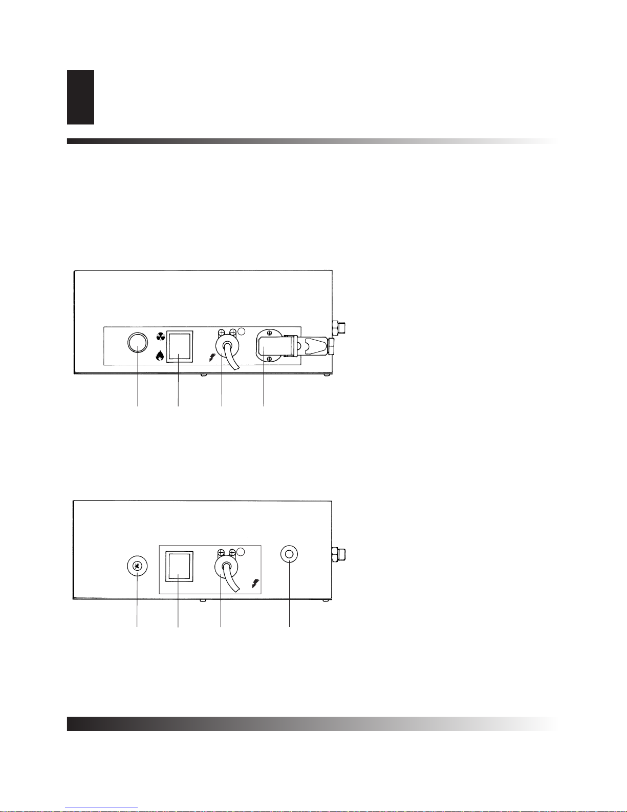
CONTROL BOARD - TABLEAU DE COMMANDE - KONTROLLTAFEL
QUADRO COMANDI - TABLEO DE MANDOS
1 Reset button with control lamp
Bouton de réarmement avec lampe témoin
Reset Knopf mit Kontrollampe
Pulsante riarmo con spia
Pulsador restablecimiento con testigo
2 Room thermostat socket
Prise de thermostat d’ambiance
Raumthermostat Steckdose
Presa termostato ambiente
Enchufetermostato ambiente
3Power cord
Câble électrique d’alimentation
Elektro kabel
Cavo alimentazione elettrica
Cable alimentación eléctrica
43 Position switch heat - 0 - ventilation
Commutateur chauffage - 0 - ventilation
3 Stellung Schalter heizung - 0 - lüftung
Commutatore riscaldamento - 0 - ventilazione
Conmutador calefacción - 0 - ventilación
5Piezo igniter
Allumeur piézo-électrique
Piezo zünder
Accenditore piezoelettrico
Encendedor piezoeléctrico
6 On-off switch
Interrupteur marche-arrêt
Ein-aus schalter
Interruttore marcia-arresto
Interruptor puesta en marcha-paro
7 Thermic gas valve
Vanne gaz-termique
Thermoventil
Valvola gas-termica
Válvula gas-térmica
“E”
“M”
RIARMO
ALARM
STÖRUNG
RESET
STACCARE CORRENTE PRIMA DI APRIRE IL QUADRO COMANDI
DEBRANCHER L’ALIMENTATION DE COURRENT AVANT D’ENLEVER LA TRAPPE
VON ÖFFNEN DER MASCHINE NETZSTECKER ZIEHEN
UNPLUG THE MACHINE BEFORE REMOVING THE COVER
0
230 V
50Hz
PE
T.A.
1
4
3 2
ON
OFF
PE
230 V
50Hz
65 7
3
Page 3
To obtain full benefit from your air heater and avoid damage, please
read the following informations and instructions carefully.
The heaters covered by this manual are suitable for use with
propane gas.
• Consult your Fire Insurance Company;
• Never allow any inflammab le materials to be used or placed near
the air heater;
• Heater must not be used close to combustible or explosiv e materials;
• Make sure fire fighting equipment is available;
• Before connecting heater to electrical supply make sure that fan
rotates freely;
• Ensure that there is a sufficient supply of fresh air into the building;
• Ensure that no obstruction prevents the heated air from flowing
out freely;
• Installation of gas bottles must be carryed out according with
local rules
• Ensure that precautions are taken to avoid accidental heating of
gas bottle and that temperature is not less than -10°C;
• The heater must be serviced regularly;
• Careful installation is essential;
• The heater must work in accordance with instructions and surrounding area should be kept clean;
• When the heater is not used, the plug should be removed from
the electrical supply.
The heater is equipped with a gas hose, stop-gas valve and gas regulator.
Refer to data plate on side of heater for electrical specifications (single phase, 230 V, 50 Hz).
Connect heater to gas cylinder (minimum 25 kg capacity) in the following order: gas hose to heater, stop gas valve to gas hose, regulator to stop gas valve, regulator to gas cylinder.
When the heater is working under the control of a thermostat or a
timer (“E” models only), connect wires of these desices to terminals
2 and 3 of the plug in the control pannel of the so me heaten. It later
you wish to make the heater run in manual mode, the bridge hase to
be fitted black.
• Set switch (4) for “E” models and (6) for “M”models on “O”/OFF
position; connect heater to mains with good earthing.
5
GENERAL INFORMATIONS
SAFETY RECOMMENDATIONS
INSTALLATION INSTRUCTIONS
OPERATING INSTRUCTIONS
STOPPING THE HEATER
VENTILATION
SAFETY DEVICES
• Set regulator at the lowest pressure and press stop gas valve
once.
• On “E” models only, set switch (6) on position ; the fan rotates
and after few seconds the combustion begins.
• On “M” models only, set switch (6) on position ON and while
keeping valve pressed, press piezo ignitor until ignition occurs.
Keep valve pressed for about 10-15 seconds, then release.
• You can now increase or decrease the output of your heater by
acting accordingly on the gas regulator.
If the heater does not start or run properly, please check follo wing
points:
1) check mains connection;
2) check that gas cylinder is full and that cylinder tap is opened;
3) press safety stop valve button;
4) on “E” models only, press the reset button up to 3 times max.
If the heater still does not run read carefully “OBSERVED FAULT,
CAUSES AND REMEDIES” chapter in this ser vice book and
make sure that the reason of malfunction is clearly located and
proper repair is made before any re-start attempt.
Set main switch (6) on “M” models and switch (4) on “E” models on
“0”/OFF position or turn thermostat or other control device on the
lowest setting (“E” models only).
Turn off gas supply and pull out mains plug.
Your heater can be used as a ventilation unit only.In this case do not
connect heater to gas cylinder.
• On “E” models set main switch (4) on position .
• On “M” models set main switch (6) on position ON.
To stop ventilation set mains switch on “O”/OFF position.
“E” models.
“E” model is equipped with an electronic de vice f or the flame control.
“E”model is moreover equipped with a device for airflow control.This
security device will prevent the flame to light in case of insufficient or
missing airflow. In case of failure the heater will stop and the pilot
lamp in the control box reset button will light up. A self-diagnostis
system will always check the airflow at start up. Airflow must be
absent at first and be present afterwards.On the contrary the heater
will stop and the control lamp (1) will light up. Avoid to start the
heater before the fan has stopped.
GENERAL INFORMATIONS
SAFETY RECOMMENDATIONS
OPERATING INSTRUCTIONS
INSTALLATION INSTRUCTIONS
STOPPING THE HEATER
VENTILATION
SAFETY DEVICES
GB
WARNING:The power supply must be provided with a good earth and magneto-thermic
mains switch.
WARNING:If the flame goes off after few seconds, turn the mains plug one half turn so as to
modify phase alignment, press control box pilot
lamp button, the heater will start again.
WARNING:All gas connections have a coun-
terclockwise thread.
Page 4

6
MOVING THE HEATER
MAINTENANCE
GB
M” models.
Flame monitoring is achieved via a thermal sensor which will cut off
gas supply in case of bad combustion or flame blame out.
“E” and “M” models are fitted with an overheat thermostatic cut off
device which will cut off gas supply in case of overheating.This safety device will automatically return to its initial function as soon as the
heater is cooled off. For that reason it is essential to locate and
repair properly the defect which has led to overheat before making
any attempt to re-start the heater.
To re-start the heater, follow instructions as indicated above.
The space heater is equipped with handle and can be moved by
pulling it up and rolling it on its wheels.
Before doing any maintenance, always stop and disconnect heater
from mains and gas cylinder. Wait till heater is cooled off. The fan
blades should be cleaned regularly. Clean also burner after having
removed combustion chamber and burner. All cleanings must be
made exclusively with compressed air.
MOVING THE HEATER
MAINTENANCE
WARNING:Avoid to direct compressed-air jet
in proximity to the micro-switch: it could be
irrecoverably damaged.
WARNING: During proper heater work, the
control lamp of the reset button can blink for
short periods for regular intersals: this doesn’t
represent a malfunction warning.
While in case of heater “block”, instead, the
warning lamp will remain on and it will periodically blink.
Page 5

7
OBSERVED FAULT, POSSIBLE CAUSES AND REMEDIES
GB
OBSERVED FAULT, POSSIBLE CAUSES AND REMEDIES
j
p
OBSERVED FAULTS
Air heater does not start 1-2-3-4-5-6 1-2-5
Air heater stops burning and lamp (1) lights up 6-7-8-9-10-11-21-22
Fan turns but the gas supply is blocked or fails to ignite 8-11-12-13-14-15
The flame extinguishes completely after the press-button (7) is released 14-16-17
Gas supply is interrupted. The flame extinguishes 10-11-12-18
Too much gas is used 18-19 18-19
Air heater cannot be switched off by means of the switch 5-6-13-20 5-20
N° CAUSE
1 No electrical supply
2 Motor is overloaded (fan blows irregularly or is blocked)
3 Thermostat or time-clock setting incorrect
4 Thermostat plug (2) not shorted
5
Switch defect: (4) on model “E” and (6) on model “M”
6 Fault in the burner relay
7 Plug wired incorrectly
8
No gas pressure up to solenoid valves
9
Solenoid valves do not open
Ionisation electrode defective and/or ignition electrode wrongly
10
usted
ad
11 Gauze protecting fan is dirty
12
Overheat thermostat cuts in
13 Thermostat out of order
14 Thermic gas valve does not remain open
15
Ignition does not work
Thermocouple does not get warm
16
17 Circuit breaker on thermocouple defective
18 Pressure regulator defect
19 Gas leakage
20 Solenoid valves do not close
21 Not enough airflow
22 Fault in air microswitch
Check that the plug is in socket and supply available
Check motor and fan and replace if necessary
Adjust setting
Make the connection (check the link connection in the plug)
Shut off the gas supply, remove plug from socket and replace switch
Replace the burner relay
Re-wire plug
Check that the gas supply is open
Check that the gas bottle(s) is (are) filled
Press the button of the safety cut off valve
Check solenoid valves
Check the electrical connection
Check the overheat thermostat
Adjust according to the instructions
lace ionisation electrode
Re
Clean the protection gauze
Check if the grilles at the inlet and outlet are dirty
Check that there is sufficient fresh air supply
Check that the heated air can flow out freely
Check the thermostat and replace, if necessary
Depress the valve button for about 10 seconds
Check line continuity between igniter and electrode
Check the setting of the electrode (see scheme)
Check the position of the thermocouple (see scheme)
Check the thermocouple and replace if necessary
Clean terminals of circuit breaker or replace
Replace pressure regulator
Locate the leak with soap-suds and replace the defective part
Close the gas supply, allow the available gas in the hose to burn, remove
plug from the socket, remove solenoid valves, clean and remount
Check if the grilles at the inlet and outlet are dirty
Check air microswitch
Model “E” Model “M”
SOLUTION
N° CAUSE
Page 6

20
WIRING DIAGRAM
SCHEMA ELECTRIQUE
ELEKTRISCHES SCHEMA
SCHEMA ELETTRICO
ESQUEMA ELÉCTRICO
WIRING DIAGRAM - SCHEMA ELECTRIQUE - ELEKTRISCHES SCHEMA
SCHEMA ELETTRICO - ESQUEMA ELÉCTRICO
EI IONISATION ELECTRODE
ELECTRODE D’IONISATION
IONISATION ELEKTRODE
ELETTRODO DI IONIZZAZIONE
ELCTRODO DE IONIZACIóN
IT TRANSFORMER H.T.
TRANSFORMATEUR H.T.
ZÜNDTRANFO
TRASFORMATORE A.T.
TRANSFORMADOR A.T.
AP CONTROL BOX
COFFRET DE SECURITE
STEÜRGERÄT
APPARECCIATURA CONTROLLO
APARATO DE CONTROL
RC RC GROUP
GROUPE RC
RC GROUPE
GRUPPO RC
GRUPO RC
TA ROOM THERMOSTAT PLUG
PRISE THERMOSTAT D’AMBIANCE
RAUMTHERMOSTAT STECKDOSE
PRESA TERMOSTATO AMBIENTE
ENCHUFE TERMOSTATO AMBIENTE
RV CONTROL KNOB - 0 - VENTILATION ONLY
COMMUTATEUR CHAUFFAGE - 0 - VENTILATION
SCHALTER HEIZUNG - 0 - LÜFTUNG
COMMUTATORE RISCALDAMENTO - 0 - VENTILAZIONE
CONMUTADOR CALEFACIóN - 0 - VENTILACION
LF ANTI-JAMMING FILTER
FILTRE ANTIPARASITES
FUNKENTSTöRFILTER
FLTRO ANTIDISTURBO
FILTRO ANTI MOLESTIA
PAM AIR MICROSWITCH
MICROINTERRUPTEUR AIR
LUFT MICROSCHALTER
MICROINTERRUTTORE ARIA
MICROCONTACTO AIRE
R1 MICROSWITCH RELAY
RELAIS MICROINTERRUPTEUR
RELAIS MICROSCHALTER
RELÈ MICROINTERRUTTORE
RELÈ MICROCONTONTACTO
MOD. “E”
Page 7

21
WIRING DIAGRAM
SCHEMA ELECTRIQUE
ELEKTRISCHES SCHEMA
SCHEMA ELETTRICO
ESQUEMA ELÉCTRICO
WIRING DIAGRAM - SCHEMA ELECTRIQUE - ELEKTRISCHES SCHEMA
SCHEMA ELETTRICO - ESQUEMA ELÉCTRICO
MV FAN MOTOR
MOTEUR DU VENTILATEUR
VENTILATOR MOTOR
MOTORE VENTILATORE
MOTOR VENTILADOR
EV SOLENOID VALVE
ELECTROVANNE
MAGNEVENTIL
ELETTROVALVOLA GAS
ELCTROVÁLVULA GAS
CT OVERHEAT THERMOSTAT
THERMOSTAT DE SURCHAUFFE
SICHEREITSTHERMOSTAT
CAPSULA TERMOSTATICA
CÁPSULA TERMOSTÁTICA
FU FUSE 4A
FUSIBLE 4A
SICHERUNG 4A
FUSIBILE 4A
FUSIBLE 4A
EA IGNITION ELECTRODE
ELECTRODE D’ALLUMAGE
ZÜNDELEKTRODE
ELETTRODO D’ACCENSIONE
ELECTRODO DE ENCENDIDO
TC THERMOCOUPLE
THERMOCOUPLE
THERMOELEMENT
TERMOCOPPIA
TERMOPAR
PZ PIEZIGNITER
PIEZOELECTRIQUE
PIEZOZÜNDER
PIEZOELETTRICO
PIEZOELÉCTRICO
IN SWITCH 0 - 1
INTERRUPTEUR 0 - 1
SCHALTER 0 - 1
INTERRUTTORE 0 - 1
INTERRUPTOR 0 - 1
DT BREAKER CIRCUIT THERMOELEMENT
DISJOINTER DE THERMOCOUPLE
ABSCHALTER FÜR THERMOELEMENT
DISGIUNTORE DI TERMOCOPPIA
DISYUNTOR SOBRE TERMOPAR
MOD. “M”
Page 8

22
ELECTRODES ADJUSTMENT AND THERMOCOUPLE
REGLAGE DES ELECTRODES ET THERMOCOUPLE
EINSTELLUNG DER ELEKTRODEN UND THERMOELEMENT
REGOLAZIONE ELETTRODO E TERMOCOPPIA
REGULACIÓN ELECTRODO Y TERMOPAR
ELECTRODES ADJUSTMENT AND THERMOCOUPE
REGLAGE DES ELECTRODES ET THERMOCOUPE
EINSTELLUNG DER ELEKTRODEN UND THERMOELEMENT
REGOLAZIONE ELETTRODO E TERMOCOPPIA
REGULACIÓN ELECTRODO Y TERMOPAR
3 ÷ 4 mm
30 mm
Page 9

23
TECHNICAL SPECIFICATIONS
CARACTERISTIQUES TECHNIQUES
TECHNISCHE DATEN
CARATTERISTICHE TECNICHE
CARACTERÍSTICAS TÉCNICAS
TECHNICAL SPECIFICATIONS - CARACTERISTIQUES TECHNIQUES - TECHNISCHE DATEN
CARATTERISTICHE TECNICHE - CARACTERÍSTICAS TÉCNICAS
DESA ITALIA s.r.l.
Via Tione, 12
37010 Pastrengo (VERONA)
www.desaitalia.com
info@desaitalia.com
DESA POLAND Sp. Z.o.o.
Ul Rolna 8, Sady
62-080 Tarnowo Podgorne, Poland
www.desapoland.pl
office@desapoland.pl
DESA UK Ltd.
United 3 Easter Court Gemini
Business Park Warrington, Cheshire
WA5 7ZB United Kingdom
TECHNICAL SPECIFICATIONS - CARACTERISTIQUES TECHNIQUES
TECHNISCHE DATEN - CARATTERISTICHE TECNICHE
CARACTERÍSTICAS TÉCNICAS
BLP 100E
BLP 100M
Max heating output - Puissance thermique max
Wärmeleistung max - Portata termica max
Potencia térmica máx
Air output - Débit d’air
Lufdurchsatz - Portata d’aria
Capacidad aire
Gas consumption - Consommmation gaz
Gas Verbrauch - Consumo gas
Consumo gas
Power supply - Alimentatione électrique
Netzanschluss - Alimentazione elettrica
Alimentación eléctrica
Total power consumption - Puissance électrique
Leistungsaufnahme - Potenza elettrica totale
Potencia eléctrica
Gas pressure - Pression gaz
Betriebsdruck - Pressione gas
Presión gas
Noise level at 1 m - Niveau sonore à 1 m
Geraüschspegel a 1 m - Livello sonoro a 1 m
Nivel sonoro a 1 m
Dimensions, L x W x H - Dimensions, L x P x H
Masse, H x B x T - Dimensioni, L x P x A
Dimensiones, L x W x H
Weight - Poids
Gewicht - Peso
Peso
Phase - Phase
Phase - Fase
Fase
Voltage - Tension
Spannung - Tensione
Tensión
Frequency - Fréquence
Frequenz - Frequenza
Frecuencia
[kW (Hi)]
[kcal/h]
3
/h]
[m
[kg/h]
[V]
[Hz]
[W]
[bar]
[dBA]
[mm]
[kg]
32,2 ÷ 96,6 32,2 ÷ 96,6
28.000 ÷ 83.000 28.000 ÷ 83.000
3.260 3.260
2,5 ÷ 7,5 2,5 ÷ 7,5
11
230 230
50 50
345 325
0,5 ÷ 2,0 0,5 ÷ 2,0
77 77
990 x 436 x 610 990 x 436 x 610
35 35
 Loading...