

Page 1
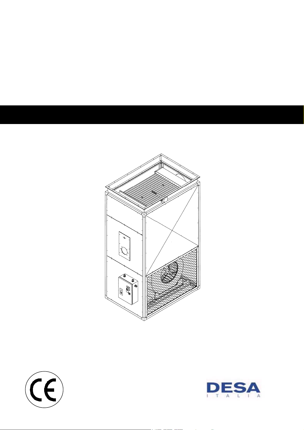
TECHNICAL INFORMATION,
ASSEMBLING INSTRUCTIONS,
USE AND MAINTENANCE
Vertical warm air heaters
BI SERIES
Page 2
Dear Customer,
Thank you for choosing a BI series AIR HEATER, an innovative and modern, quality and high
performance product which will assure safe and silent working for a long time. This is
particularly the case if the heater is put in the hands of DESA ITALIA Technical Assistance
Department which is specially trained end equipped to keep it working at maximum efficiency
with low running costs and has a large number of original spare parts in stock.
This instruction manual contains important instructions and suggestions for simple installation
and making the best use of the BI air heater.
Once again, thank you.
DESA ITALIA s.p.a.
RANGE
This manual refers to TYPE. In the follo wing chart yo u will find the heaters rang e and the correspond ence b et ween Type
and the Commercial and the Trade Name.
TYPE MODEL
1 BI 60
2 BI 95
3 BI 105
4 BI 120
5 BI 160
6 BI 190
7 BI 225
8 BI 260
9 BI 320
10 BI 390
11 BI 590
12 BI 645
13 BI 770
14 BI 1000
15 BI 1100
GUARANTEE
The BI heater has a SPECIFIC GUARANTEE running from the date of the purchase, of which the customer must notify
the manufacturer. If he is unable to do so the guarantee shall run from the date of manufacture. The details of the
guarantee conditions are given in the GUARANTEE CERTIFICAT E supplied with the equipment, and which we suggest
the Customer read with care.
2
Page 3

INDEX
GENERAL
RANGE ............................................................................................................................................................................... 2
GUARANTEE ...................................................................................................................................................................... 2
GENERAL WARNINGS ...................................................................................................................................................... 4
BASIC SAFETY RULES...................................................................................................................................................... 5
DESCRIPTION OF THE EQUIPMENT ............................................................................................................................... 6
IDENTIFICATION ................................................................................................................................................................ 7
STRUCTURE ...................................................................................................................................................................... 7
COMBUSTION CHAMBER DIMENSIONS ......................................................................................................................... 8
DIMENSIONS ..................................................................................................................................................................... 9
TECHNICAL DATA ........................................................................................................................................................... 10
HANDLING AND TRANSPORTATION ............................................................................................................................. 11
LOCATION ........................................................................................................................................................................ 12
FUEL CONNECTION ........................................................................................................................................................ 12
FLUE ................................................................................................................................................................................. 12
AIR INLET CONNECTION ................................................................................................................................................ 13
AIR OUTLET CONNECTION ............................................................................................................................................ 13
FIXED PROTECTIONS ..................................................................................................................................................... 13
DIFFUSION PLENUM ....................................................................................................................................................... 13
AIR INLET FILTER ............................................................................................................................................................ 15
MOUNTING THE BURNER .............................................................................................................................................. 16
ELECTRICAL CONNECTION ........................................................................................................................................... 16
TYPE 1 WIRING DIAGRAM .............................................................................................................................................. 17
TYPE 2 TO 10 WIRING DIAGRAM ................................................................................................................................... 18
TYPES 11 TO 14 WIRING DIAGRAM .............................................................................................................................. 19
TYPE 15 WIRING DIAGRAM ............................................................................................................................................ 20
FAN-LIMIT DUAL THERMOSTAT .................................................................................................................................... 22
POSITIONING OF FAN, LIMIT AND SAFETY THERMOSTATS ...................................................................................... 22
FAN-LIMIT-SAFETY THERMOSTATS SETTING ............................................................................................................. 24
FAN START TIMER .......................................................................................................................................................... 25
SETTINGS ........................................................................................................................................................................ 25
OIL-FIRED BURNER SETTING ........................................................................................................................................ 26
FAN SPEED SET-UP ........................................................................................................................................................ 27
CHECKS ........................................................................................................................................................................... 28
CONTROLS ...................................................................................................................................................................... 28
INDICATORS .................................................................................................................................................................... 29
FAN MOTOR ABSORPTION ............................................................................................................................................ 29
WORKING CYCLE ............................................................................................................................................................ 29
START UP AND STOP ..................................................................................................................................................... 30
MAINTENANCE ................................................................................................................................................................ 30
AIR FILTER CLEANING .................................................................................................................................................... 30
BURNER CLEANING ........................................................................................................................................................ 31
HEAT EXCHANGER CLEANING ...................................................................................................................................... 31
FAN MAINTENANCE ........................................................................................................................................................ 32
LIMIT THERMOSTAT MAINTENANCE ............................................................................................................................ 32
FUME SAMPLING POSITION .......................................................................................................................................... 32
ASSISTANCE ................................................................................................................................................................... 32
FAULTS AND SOLUTIONS .............................................................................................................................................. 33
The following symbols are used in the manual:
WARNING= Where the work to be carried out requires special care and suitable training.
FORBIDDEN= Where the action MUST NOT be carried out.
This manual consists of 36 pages.
3
Page 4
GENERAL WARNINGS
This instruction booklet is an integral part of the
equipment and so it has to be carefully kept at all
times and always accompany the equipment if it
passes to another owner. If the instruction
booklet gets damaged or lost, ask DESA ITALIA
local technical assistance dept. for another copy.
After removing the packaging, check that all the
equipment is present and intact. If there is any
failure to correspond with order contact your
DESA ITALIA agent who sold the equipment.
The BI warm air heater must be installed by an
accredited company in accordance with the law
46 of 5
statement that the equipment has been properly
installed, i.e. in observance of current legislation
and the instructions given by DESA ITALIA in
this manual.
These machines are designed to heat rooms
and must be used for this in accordance with
their performance characteristics. DESA ITALIA
shall not be contractually or otherwise liable for
any damage caused to people, animals or items
because of installation mistakes, failure to
observe the rules or improper use.
A too high temperature is harmful to health and
is also a waster of energy. Do not keep rooms
closed for long periods: periodically open
windows to change stale air.
The first time the equipment gets switched on,
there may is some smell or fumes caused by the
evaporation of the liquid protecting the heat
exchanger during storage: this is normal and will
disappear after a short period. It is advisable to
keep rooms ventilated.
If the equipment remains idle for long periods,
carry out the following operations at least:
Put the main electrical switch off;
Close the main fuel supply tap.
If the heater is idle for long periods, it is
advisable to contact DESA ITALIA Technical
Assistance Department or other professionally
qualified people to restart it.
th
March 1990, which shall issue a
Only original accessories must be used on the
equipment. DESA ITALIA shall not be held liable
for any damage deriving from improper sue or
non original materials or accessories.
Laws, standards, directives and technical rules
referred to in this booklet are only for your
information and shall be considered vali d onl y as
of the time of going to press. Any new provisions
which come into effect or any amendments to
current provisions shall not give rise to any
obligations for DESA ITALIA as against third
parts.
Repairs and maintenance must be carried out by
DESA ITALIA Technical Assistance Department
or by qualified staff as indicated in this booklet.
Do not make modifications to or tamper with the
equipment as this may cause dangerous
situations to arise and the manufacturer will no
longer be responsible for any damage caused.
The plant and utilities must be connected and
affixed properly (i.e electrical supply etc.) and
must not cause obstructions which may be
tripped over.
DESA ITALIA is responsible for its product’s
compliance with the laws, directives or building
standards in force at the time of its sale. The
design engeneer, installer and user are
respectively and entirely responsible of their
awareness of and observance of the legislative
provisions and standards dealing with plant
design, installation, the working and
maintenance of the equipment.
DESA ITALIA shall not be held liable for any
failures to observe the instructions contained in
this booklet, for the consequences of any
handling or usage not specifically provided for or
for any translations which may be subject to
erroneous interpretation.
This machine has been projected to work with
the heat rate and ait throughput values as
indicated in the Technical Data paragraph. A too
low heat rate and/or a too high air throughput
might lead to the condensation of the
combustion products, with a consequent
irreparable corrosion of the heat exchanger. A
too high heat rate and/or a too low air throughput
might lead to an anomalous overheating of the
heat exchanger with a consequent cut-in of the
safety devices and damage of the echanger.
4
Page 5
BASIC SAFETY RULES
We remind you that the use of products needing electrical energy, gas or heating oil requires the observanc e of some
basic safety rules, including the following:
The unassisted use of air heaters by children or
disabled people is forbidden.
Electrical devices or equipment such as
switches, domestic appliances etc. must not be
used if there is a smell of fuel or unburnt gases
etc. In such cases:
Ventilate the room by opening doors and
windows;
Close the fuel shut-off;
Call the DESA ITALIA Technical Assistance
Dept. or other professionally qualified
personnel.
The equipment must not be touched being
barefeet of with wet or damp parts of the body.
Cleaning and maintenance operations on the
equipment must be carried out only when it is
switched off with the main electrical switch if the
‘off’ position, and with the fuel supply cut off.
It is forbidden to interfere with or alter the safety
or regulatory systems without prior authorisation
and without following the manufacturer’s
instructions.
It is forbidden to pull or twist the electric cables
coming out from the equipment, even if the
equipment is disconnected from the main
electricity supplies.
Before entering the access doors to the internal
parts of the equipment, the main switch must be
turned to ‘off’.
It is forbidden to throw away, abandon or leave
the packaging material (cardboard, fasteners,
plastic bags etc.) within the reach of children, as
they may be a source of danger.
It is forbidden to install the equipment near
to flammable materials or where there are
aggressive agents in the atmosphere.
It is forbidden to put objects on top of the
equipment or push them inside the boy shell grill
and exhaust discharge dust.
The exhaust flue must not be touched as it may
reach temperatures which are dangerously h igh
to the touch during normal working.
It is forbidden to use adapters, multiple sockets
and extension cables for the equipment
electrical connection.
It is not permitted to install the equipment
outdoors or in any place where it will be subject
to atmospheric agents.
It is forbidden to directly install the equipment in
restricted rooms with no fitting ventilation since
the air aspiration might cause a strong
depression inside the room, leading to serious
inconveniences.
5
Page 6

DESCRIPTION OF THE EQUIPMENT
The BI equipment is designed to heat the air in the room using heat en ergy produces by combustion. Essentially the
equipment consists of heat exchanger assemblies exchanging heat from the combustio n by-products from a forced gas
or heating fuel oil burner by a high performance fan assemb ly. The air to be heated is aspired by the latter and flows
against the heat exchange where its temperature rises to then be distributed either immediately or via suitable
channelling. The particular features of the centrifugal fan make the equipment well sui ted for installation where hot air
needs to be distributed through channels or generally where it is necessary to have static pressure available. A special
flange (both on inlet and outlet) enables the equipment to be connected up the channelling.
This system gives a notable reduction in the costs of the plant and also works economically, making itself particularl y
suitable where it is expected it be used intermittently or oc casionally. The equipment is designed so that it can also be
used to provide ventilation only during the summer months.
GENERAL STRUCTURE FEATURES
Heat exchanger
Built with welded steel and steal-tested in accordance with t he UNI-CIG 9462 standar ds, i t is eas y to be i nspected for the
normal cleaning and maintenance operations. It consists of:
Combustion chamber in low thermal load stainless steel with suitable shape and size;
Exchange elements in stainless steel, with modular, large surface sections with swirl impressions for an optimal heat
exchange;
Exhaust manifolds in fine steel.
External casing
The external casing consists of removable panels in pre-painted steel and also includes:
Insulation of the surfaces exposed to radiant heat from the heat exchanger;
Delivery air flange for connection to the hot air distribution circuit;
Intake guard with flanges for connection to the intake circuit.
Fan assembly
One or more high performance centrifugal fans producing low noise emissions. These are run by electrical motors
connected to a pulley and belt system. The motor has got an adjustable pulley (type 1 to type 10) which means the
system can be easily adapted to the particular needs of the customer’s premises.
Control and safety thermostats
The heater has a dual thermostat which is calibrated and electrically connected to perform the following functions:
"FAN" function (25-35°C, FAN thermostat) - controls fan start up about 60 seconds after burner ignition and stops
the fan about 4 minutes after the burner has stopped. This prevents unpleasant cold air being conveyed into the room
on start up und utilises the stored heat in the heat exchangers after the burner has been switched off.
“SAFETY” function (type 5 to 15, TR thermostat) – preset at 80°C, it has th e function of stopping the bruner in
case of anomalous overheating of the air. Automatic reset, the correct setting has to be set during the first stat-up.
"LIMIT" function (sealed setting 100°C, LM thermostat) – manual reset, switches the burner off in case of
overheating of the air.
Fume discharge outlet
The equipment has a circular outlet to which a metal exhaust pipe can be connected and safely joined.
6
Page 7
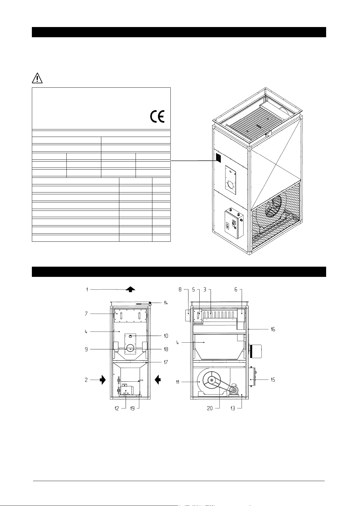
IDENTIFICATION
Hot air generators are identifiable by:
The Technical Plate bearing their main technical and performance details. The plate is located on the front of the
equipment.
If the Plate gets lost or damaged, ask for a duplicate from DESA ITALIA Technical Department.
MANUFACTURER
IDENTIFICATION
Model
Serial number
Country PIN
Code
Type Year
Thermal capacity Kw
Thermal power Kw
Air flow (+20°C) m3/h
Working static pressure Pa
Electrical supply
Fan motor power Kw
Max fan current Pa
Protection rating IP 20
AIR HEATER
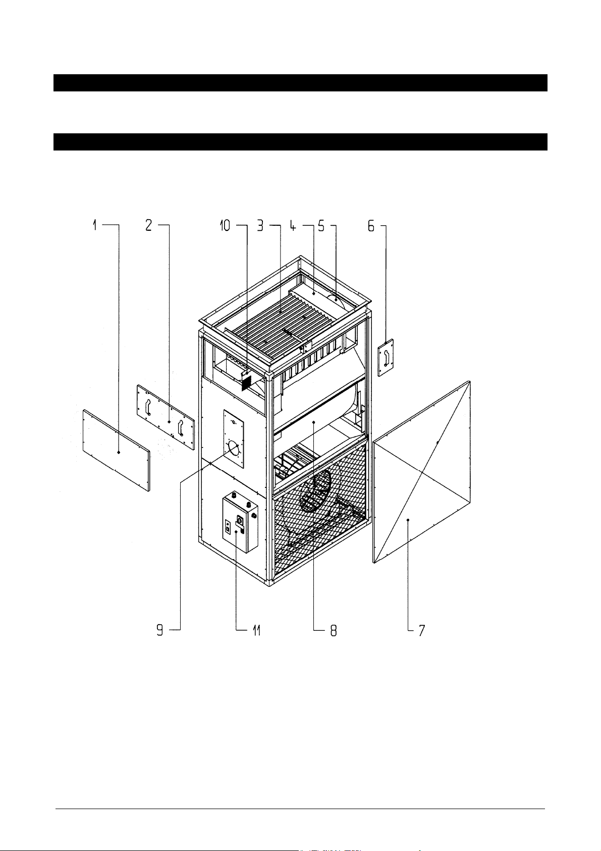
STRUCTURE
1. Air outlet
2. Air aspiration
3. Fume tubes
4. Combustion chamber
5. Back fume manifold
6. Front fume manifold
7. Inspection doors
8. Chimney
9. Burner flange
10. Combustion viewer
11. Centrifugal fan/s
12. Electric motor
13. Belt tightener
14. Dual thermostat
15. Electric equipment
16. Casing
17. Base attaching screws
18. Burner outlet
19. Motor mount plate
20. Transmission
7
Page 8
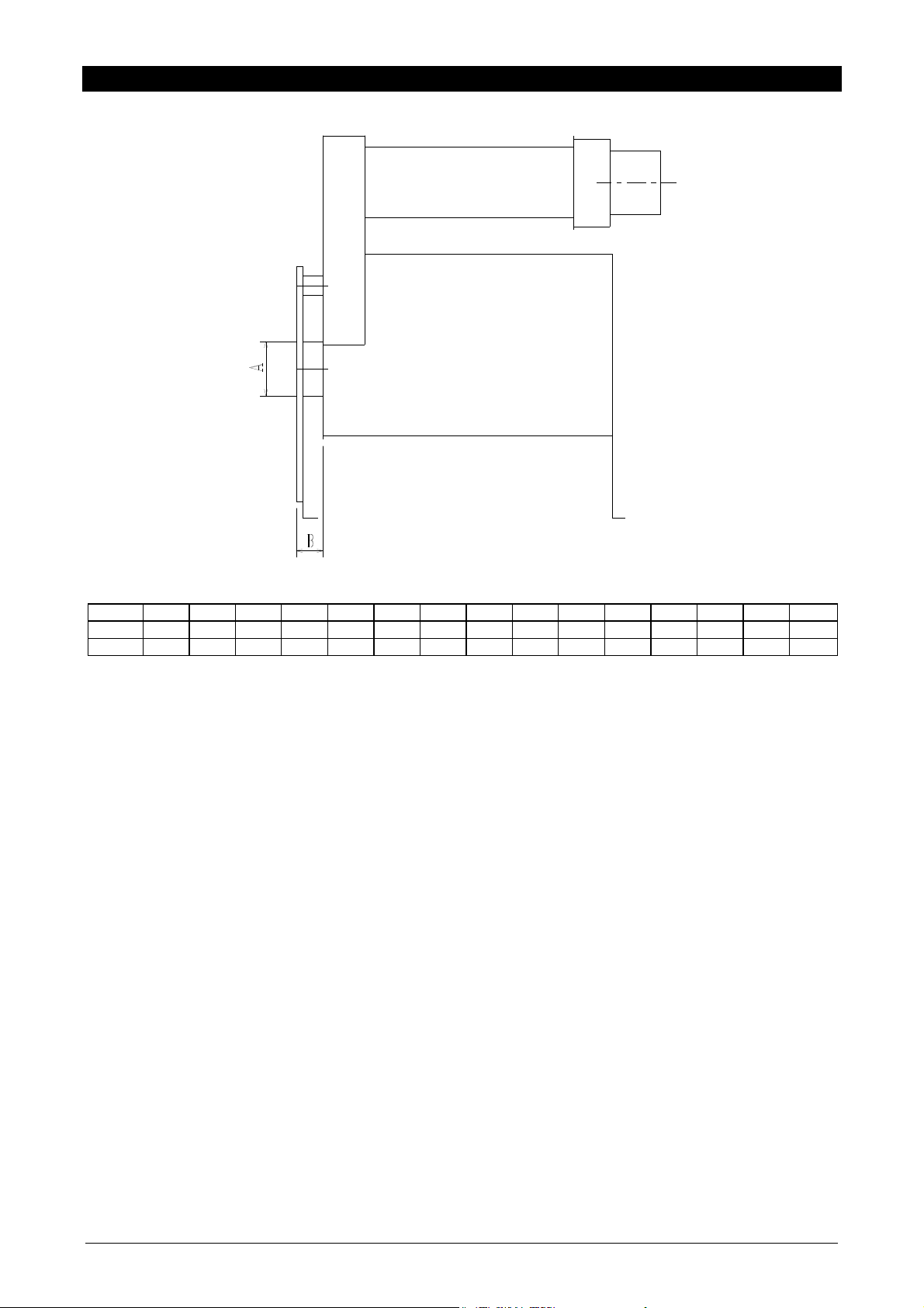
COMBUSTION CHAMBER DIMENSIONS
The three fume-cycle heat exchanger and combustion chamber have the follo wing dimensions.
TYPE 1 2 3 4 5 6789101112 13 1415
A
120 150 170 170 170 170 220 220 220 220 300 300 300 300 300
B
Measurements in millimetres;
80 80 80 80 150 150 130 130 130 130 140 140 150 150 180
8
Page 9
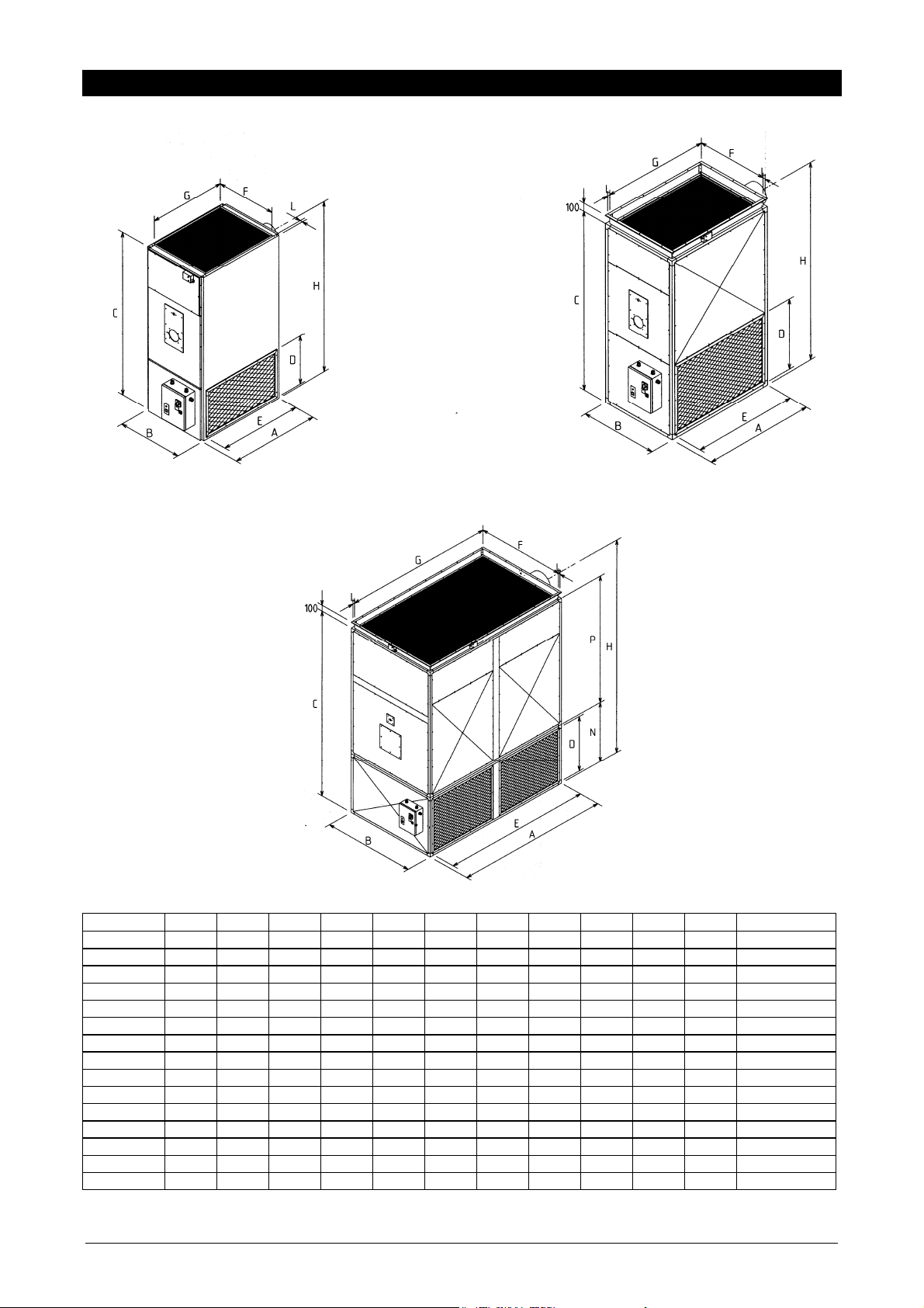
DIMENSIONS
Type 14 Type 510
Type 1115
Type A B C D E F G H L N P
1
2
3
4
5
6
7
8
9
10
11
12
13
14
15
812 540 1580 400 625 490 600 1305 27 150
890 680 1800 500 715 630 700 1475 27 180
1060 760 1926 500 900 700 900 1667 30 200
1060 760 1926 500 900 700 900 1667 30 200
1300 900 2120 781 1182 840 1240 1905 30 250
1300 900 2120 781 1182 840 1240 1905 30 250
1500 1000 2120 781 1382 940 1440 1905 30 250
1500 1000 2120 781 1382 940 1440 1905 30 250
1700 1200 2350 781 1582 1140 1640 2160 30 300
1700 1200 2350 781 1582 1140 1640 2160 30 300
2090 1270 2870 882 1972 1210 2030 2585 30 1000 1870 330
2090 1270 2870 882 1972 1210 2030 2585 30 1000 1870 330
2500 1500 3120 882 2382 1440 2440 2815 30 1000 2120 370
2500 1500 3120 882 2382 1440 2440 2815 30 1000 2120 370
3500 1500 3120 882 3382 1440 3440 2815 30 1000 2120 380
Measurements in millimetres;
chimney
9
Page 10
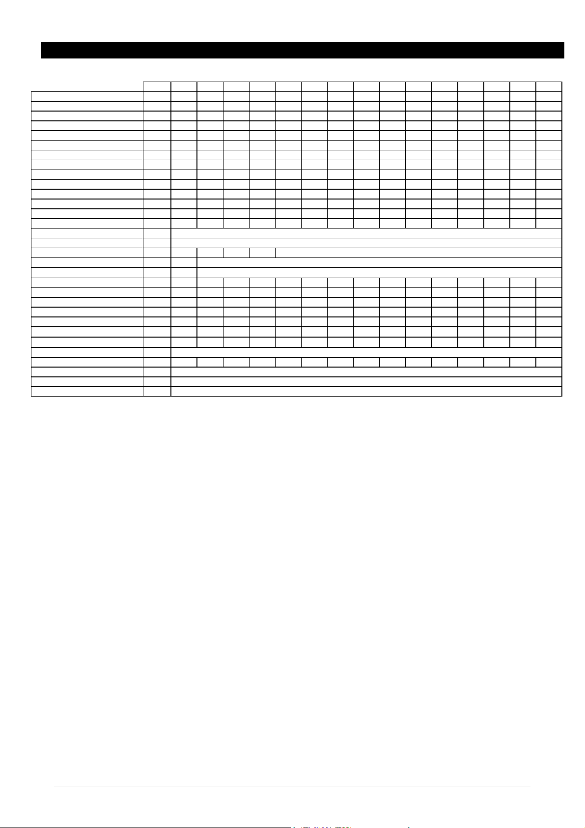
TECHNICAL DATA
+
Heating capacity KW 60,0 94,0 103,2 122,3 161,2 190,0 225,8 258,8 322,6 391,0 460,6 590,0 645,3 769,0 1000
Kcal/h 51600 80850 88790 105150 138600 163400 194225 222600 277470 336250 396160 507300 554940 661500 860000
Heating power Kw 54,0 82,2 93,0 107,0 145,3 168,2 203,5 230,3 290,7 347,6 415,0 523,2 581,4 682,9 883,7
Efficiency % 90,1 87,4 90,1 87,5 90,1 88,5 90,1 89,0 90,1 88,9 90,1 88,7 90,1 88,8 88,3
Combustion chamber pressure Pa 20 25 8 22 8 2 17 39 21 32 20 20 20 23 10
Combustion chamber volume m3 0,08 0,13 0,23 0,23 0,49 0,49 0,64 0,64 1,05 1,05 1,62 1,62 2,7 2,7 4,36
Net fumes temperature °C 200 252 206 252 210 249 205 248 204 227 205 238 192 237 260
Combustion by-products mass Kg/h 117,7 183,8 194,6 238,0 295,6 343,4 424,5 472,5 614,5 736,2 912,8 1101,0 1253,0 1422,0 1731,4
Fuel consumption
- oil kg/h 5,06 7,9 8,7 10,3 13,6 16,0 19,0 21,8 27,2 32,9 40,8 49,7 54,4 64,8 84,3
Air flow rate at +20°C m3/h 4300 6000 7600 7600 9600 11500 13400 15300 19000 23000 28700 34500 40200 49000 67000
Working static pressure Pa 160 160 160 160 220 200 200 180 200 170 280 220 220 180 200
Thermal jump K 37 40 37 42 45 43 45 45 45 45 42 45 43 42 39
LIMIT thermostat setting °C 100
FAN thermostat setting °C 25-35
SAFETY thermostat setting °C - - - - 80
Electrical supply type mono three-phase
Electrical tension V-50Hz
Fan motor electrical power Cv 0,75 1,50 2,00 2,00 3,00 4,00 4,00 5,50 5,50 7,50 10,0 12,5 15,00 20,00 2x12,5
kW 0,55 1,10 1,50 1,50 2,20 3,00 3,00 4,00 4,00 5,50 7,50 9,00 11,00 15,00 2x9,0
Electrical power
- oil burner Kw 0,17 0,17 0,38 0,38 0,38 0,37 0,37 0,37 0,37 0,45 0,65 0,65 1,10 1,10 1,80
Fan motor absorption
- 230V 50Hz
- 400V 50Hz 3N
Electrical protection rating IP 20
Net weight (2) Kg 130 180 249 249 412 437 520 525 694 734 1072 1162 1497 1622 2090
Category II
Type B23
Working field °C -15 / +40
1. Net weight expressed in Kg, without oil burner;
The declared aeraulic do not consider the head losses due to eventual accessoires (filters, blast gate damper,
aspiration grates etc.).
TYPE 1 2 3 4 5 6 7 8 9 10 11 12 13 14 15
kcal/h 46450 70700 80000 92000 125000 144600 175000 198100 250000 298950 356900 450000 500000 587400 760000
230 400 3N
A 3,7 4,8 6,4 6,4 8,8 12,1 12,1 15,8 15,8 20,7 28,6 32,9 38,9 53,6 2x33,0
A 2,8 3,6 3,6 5,1 7,0 7,0 9,1 9,1 12,0 16,5 19,0 22,5 31,0 2x19,0
2H3
10
Page 11
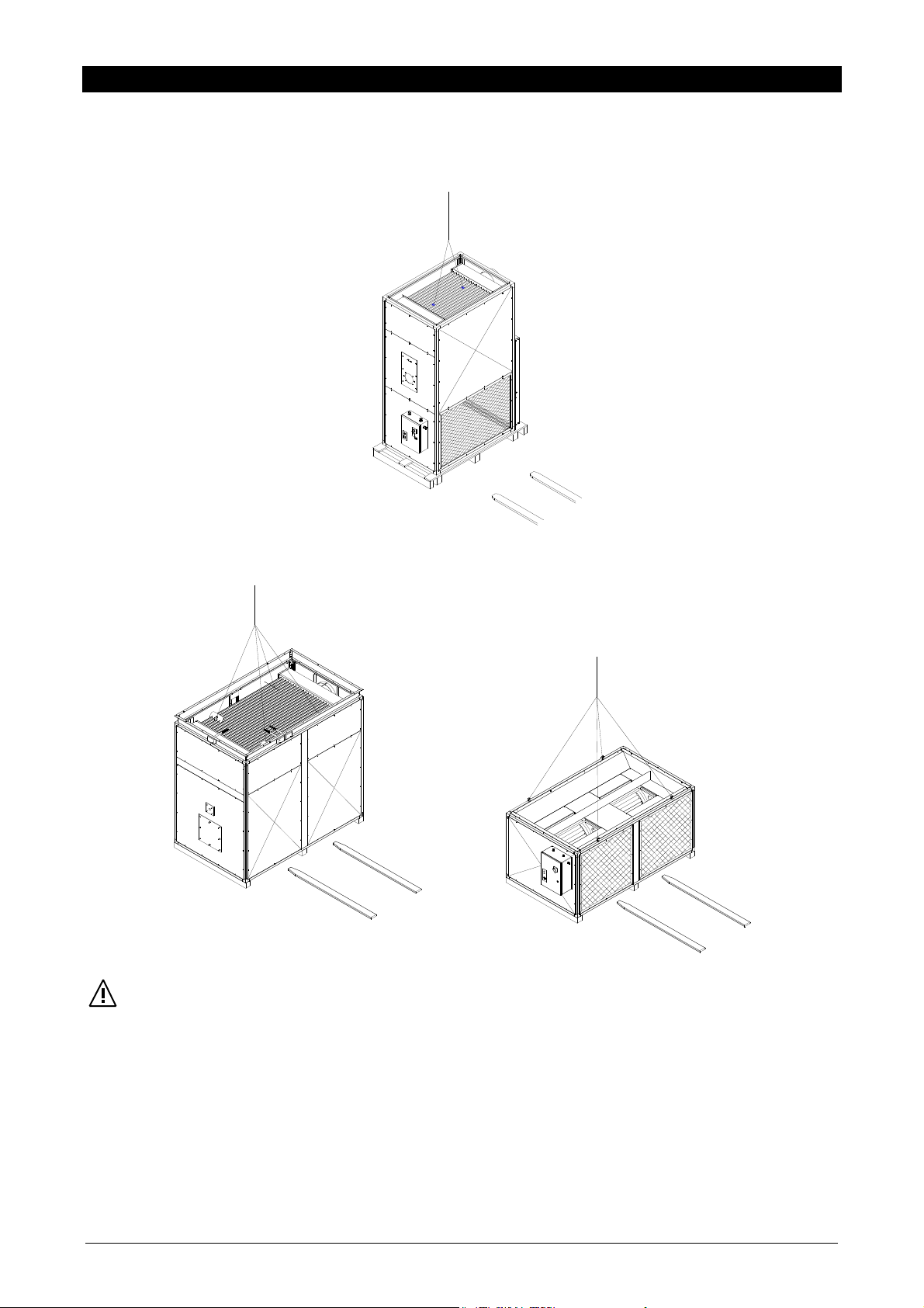
HANDLING AND TRANSPORTATION
Moving the equipment must be carried out by properly equipped personnel with equipment which is suitable for the
weight of the heater. If a fork lift is used, the equipment should be taken up at the bottom using the guides in the
supporting base. If a crane is employed use the eye-bolts at the top of the heat exchanger to lift the equipment.
Type 110
Type 1115
WARNING!
Handling and transportation must be carried out with the greatest care to avoid damage the equipment and putting
people in danger.
It is forbidden for people to stand close to the equipment during handling and trans portation manoeuvres.
It is forbidden to stack more pieces of equipment than the indication on the pack aging itself and the greatest care must
be taken in aligning the packages so that they are stable.
If the equipment must be moved by hand, ensure that sufficient human strength is available for the task in relation to t he
weights indicated in the paragraph “TECHNICAL DATA” and to where and how far the equipment has to be moved.
The use of protective gloves is advisable.
11
Page 12
LOCATION
The place of installation must be established by the plant project engin eer or competent person and must take account of
the technical requirements and current legislation and regula tions which demand the obtaining of an authorisation (e.g.
building, architectural and fire regulations, environmental legislation and so on). Before installing the equipment it is
therefore advisable to apply for and obtain all the necessary authorisations.
To be correctly installed, the BI series heater has to satisfy the following:
Be placed on a level surface which is able to support its weight;
Observe the distances indicated in this manual so that there is a proper air flow and the normal cleaning and
maintenance operations can be properly carried out;
Maintain the safety distances from flammable materials;
Be easily connected to a flue;
Be easily connected uo to the fuel tank;
Be near to an electrical socket;
Allow easy carrying out of maintenance and monitoring ope r ations;
Have the openings and ventilation required by the law in force.
The installation is not advisable:
In aggressive atmosphere rooms;
In tight rooms where the sound level of the heater might be amplified by reverberations or resonances;
In coins where it might settle leaves or anything else might obstruct the air flow, reducing the equipment efficiency;
Outside;
In depressed rooms.
WARNING!
The hot air generators types 11 to 15 are, for ease of transport, shipped in t wo separated sections (base and body). To
install, proceed as follows:
Position the base so that the electrical panel is on the same side as the burner;
Mount the centring pins provided on the upper part of the base;
Place the body over the base making sure that the two frames are perfectly aligned.
FUEL CONNECTION
The oil connection must be carried out by the authorised and qualified personnel who must follow the indications in the
manual strictly as well as the law currently in force.
FLUE
The fume channel and connection to the flue must be in acc ordance with the law and regulations currently in force, using
rigid pipes resistant to mechanical, thermal and chemical stresses resulting from combustion. Recommendations:
Avoid or at least limit the horizontal stretches which must in any case tend in an upward direction;
Use piping with smooth inner surfaces made from a suitable material which is resistant to the thermal and chemical
stresses caused by combustion, with a diameter equal to or larger than that of the connector on the equipment it self;
Avoid sharp bend and diameter reductions;
Place in the system a well for taking samples for analyses of the combustion by-products.
The chimney has to ensure the minimal depression previe wed by the Regulations in force, considering as “zero” the
pressure at the flue connection (see chart page 8).
The non-insulated discharge channels might be a source of danger.
Unfitting or badly dimensioned flues or discharge channels might amplificate the combustion sound level and
negatively affect the combustion parameters.
The tightness of the joints has to be realized with materials resistant at temperature of at least 350° C (e.g. filler,
mastic, silicones preparations).
12
Page 13

AIR INLET CONNECTION
Connect any eventual channelling to the hot air distribution ci rcuit to the equipment upper delivery flange, interposing a
vibration damper joint to prevent vibrations being transmitted to the pipes.
WARNING!
The dimensioning of eventual air inlet and outlet channels has to be previewed by qualified personnel in
compliance with the maximal performances of the heater as indicated in the “TECHNICAL DATA”.
AIR OUTLET CONNECTION
Connect any channelling in the air recovery circuit to the side o pening. T he equipment is made to take the co nnection o n
the left and on the right side. To adapt the air intake side it is enough to invert the mounting of the side closing panel/s
with the intake grid/s.
FIXED PROTECTIONS
To prevent accidental contact with the moving parts of the heat er, it is not allowed to remove the equipment perman ent
guards and protections, which consist of the following:
Air recovery grid/s;
Side closing panel/s;
Burner guard.
DIFFUSION PLENUM
If the heater is to be installed inside the room to be heated, it is necessary to use a diffusion ple num which is supplied as
an accessory. To obtain optimal air diffusion it is recommended that the equipment gets installed close to a perimeter
wall, or at the centre of the room itself, with the air delivery on three or four sides respectively.
DIMENSIONAL FEATURES
Type A B H Openings N° Air terminal dimensions
1
2
3
4
5
6
7
8
9
10
11
12
13
14
15
540 800 350 4 250 X 400
680 890 550 4 600 X 400
760 1060 550 4 600 X 400
760 1060 550 4 600 X 400
900 1300 550 4 800 X 400
900 1300 550 4 800 X 400
1000 1500 550 4 800 X 400
1000 1500 550 4 800 X 400
1200 1700 550 4 1000 X 400
1200 1700 550 4 1000 X 400
1270 2090 550 6 800 X 400
1270 2090 550 6 800 X 400
1500 2500 550 6 1000 X 400
1500 2500 550 6 1000 X 400
1500 3500 550 8 1000 X 400
13
Page 14

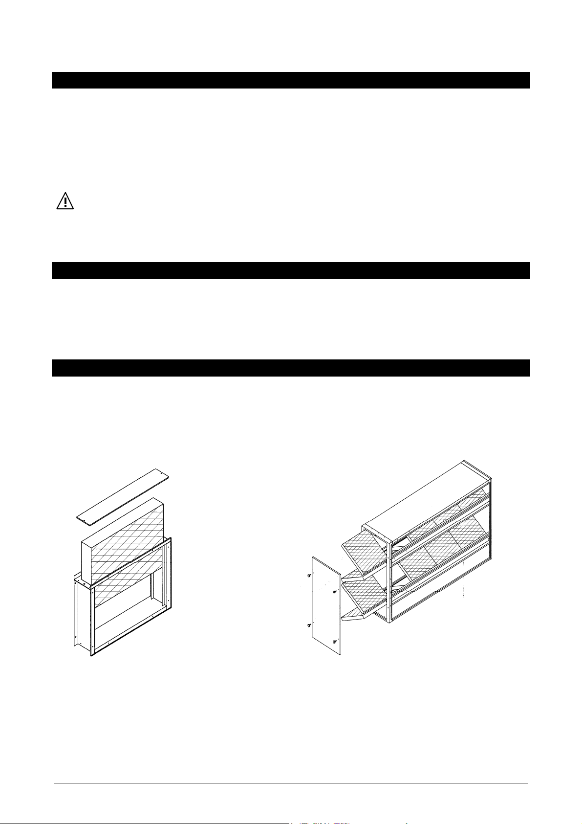
MOUNTING INSTRUCTIONS
Free the diffusion plenum from its packaging;
Remove the delivery air outlets and the closing panel from the plenum;
Place the plenum on the top of the equipment;
Fix the plenum to the equipment using the screws provided, entering through the delivery outlet openin gs and the
closing panel;
Remount the delivery outlets and the closing panel.
WARNING!
The plenum top surface cannot be walked on.
THROW DISTANCE
The scheme shows the throw distances in metres at which the rem ainin g v elocit y is red uc ed to 0.1 m/s d epe nding on th e
inclination of the fins per individual plenum with one, two or three openings.
Opening on 2 sides Opening on 3 sides Opening on 4 sides
Fin inclination 0° 20° 30° 45° 0° 20° 30° 45° 0° 20° 30° 45°
1
2
3
4
5
6
7
8
9
10
11
12
13
14
15
WARNING!
It is not allowed to have air diffused from one side only of the plenum.
44 35 28 21 36 29 23 17 31 25 20 15
42 33 27 20 34 27 22 16 29 24 19 14
48 39 31 23 40 31 26 19 35 28 22 16
48 39 31 23 40 31 26 19 35 28 22 16
59 46 38 28 48 38 31 23 42 33 27 20
75 60 48 36 61 48 40 29 54 43 33 25
82 65 53 39 67 53 44 32 58 47 38 27
93 74 60 45 76 60 49 36 66 54 44 32
106 80 63 46 82 63 52 39 68 54 45 34
112 88 72 54 91 72 59 43 79 63 51 38
104 82 68 56 79 66 54 45 70 55 45 37
122 97 80 66 98 77 64 53 81 64 53 44
147 116 96 80 118 93 77 64 98 77 64 53
147 116 96 80 118 93 77 64 98 77 64 53
164 134 116 102 134 106 95 76 116 89 74 61
14
Page 15

AIR INLET FILTER
Type 1 2 34 5 6789101112 13 1415
A
B
C
Cells N°
P (Pa)
690 780 965 965 1300 1300 1500 1500 1700 1700 2090 2090 2500 2500 3500
459 559 559 559 832 832 832 832 832 832 1000 1000 1000 1000 1000
115 165 165 165 325 325 325 450 450 450 450 450 450 450 450
1 1 1 1 4 4 6 6 9 9 12 12 12 12 24
12 20 23 23 17 27 25 35 23 38 32 45 35 50 70
MOUNTING INSTRUCTIONS
Type 14 Type 515
Type 14
Determine the filter mounting side;
Mount the filter using the screws supplied.
Type 5
Extract the filtering cells from the frame;
Determine the filter mounting side;
Mount the filter using the screws supplied;
15
Reinsert the filtering cells.
15
Page 16

MOUNTING THE BURNER
To proceed with the installation of the oil burner, respect a nd follow the instructions contai ned in the specifically manual
of the burner in detail.
ELECTRICAL CONNECTION
The equipment is supplied with the electrical panel mounted as standard and with the motor/s and the FAN-LIMIT
thermostat/s connected. The connections to be carried out are therefore the following:
The mains electrical connection;
The connections to the burner;
The connections to the room thermostat;
Any other accessories (fire barrier lock, humidifier, etc.).
For all connections use the cable grips in the electrical a nd the terminal block in the panel itself, in accordance with the
specific wiring diagram for each equipment model.
WARNING!
Install a magnetothermal switch before the equipm ent of suitable size based on the technical details indicated in the
paragraph “Technical and performance features” and in accordance with the law in force.
Have authorised personnel to check out the cabl e diameters and maximum electrical plant power absorption by the
equipment as indicated on the plate;
Always earth the equipment. Leave the eart h cable a little longer than the line wires so that, if they are accidentally
pulled, it is the last to get detached;
Respect the polarities when making the electrical connections.
In order to shut off the burner if there is any fault, the electrical pane l has a safety relay ( LX) with a conta ct connected in
series with the burner if the equipment safety thermostat is triggered (LM) or when the fan assembly stops du e to the
activation of the motor thermal relay.
ELECTRICITY SUPPLY DIMENSIONING CHART
Type Supply Maximal Maximal Main Motor Auxiliary Burner Line Earth
voltage Installed
(Kw) (A) (A) (A) (A) (A) (mm2) (mm2)
1
230V 50Hz
2
400V 50Hz 3N
3
400V 50Hz 3N
4
400V 50Hz 3N
5
400V 50Hz 3N
6
400V 50Hz 3N
7
400V 50Hz 3N
8
400V 50Hz 3N
9
400V 50Hz 3N
10
400V 50Hz 3N
11
400V 50Hz 3N
12
400V 50Hz 3N
13
400V 50Hz 3N
14
400V 50Hz 3N
15
400V 50Hz 3N
power (1)
0,55 3,7 - - 6,3 - 1,5 1,5
1,10 2,8 25 6 2 2 1,5 1,5
1,50 3,7 25 6 2 2 1,5 1,5
1,50 3,7 25 6 2 2 1,5 1,5
2,20 5,2 25 6 2 2 1,5 1,5
3 7,1 25 12 2 2 2,5 2,5
3 7,1 25 12 2 4 2,5 2,5
4 9,2 25 16 2 4 2,5 2,5
4 9,2 25 16 2 4 2,5 2,5
5,50 12,1 25 16 2 4 2,5 2,5
7,50 16,5 40 20 4 2 2.5 2.5
9 19 63 32 4 10 4 4
11 22,5 63 32 4 4 4 4
15 31 80 40 4 4 6 6
2x9 2x19 80 32 4 6 10 10
(1) Without burner;
(2) Included with the heater supply;
(3) The cable section ensures a less than 5% voltage drop over a length of 30 m.
absorbed
current (1)
breaker fuses (1) fuses(2) fuses (2) conductor
section (3)
conductor
section (3)
16
Page 17

TYPE 1 WIRING DIAGRAM
230V ~ 50 Hz
PA
LM
F
CV
TA
MS
C
SWITCHBOARD CONNECTING TERMINAL
FAN
ELECTRICITY SUPPLY
Contents:
FAN - FAN Thermostat (25-35°C)
LM - LIMIT Thermostat (100°C)
F - Safety fuses
PA - Motor internal protection
G - Fan motor
C - Fan motor condense
B - Burner
CV - Heating/stop/ventilation switch
TA* - Room thermostat
IMT* - Magnetothermal switch
MS* - (possibe) micro fire barrier lock
* External to the equipment and not included in the supply. To be installed by the customer.
230 V ~ 50 Hz
17
Page 18

SU
400V~ 3+N 50 Hz
TYPE 2 TO 10 WIRING DIAGRAM
IG
FV
LV
RTV
RTV
FA
FB
LX
TR
LM
LV
FAN
LXV
SWITCHBOARD CONNECTING TERMINAL
MONOPHASIC BURNER ELECTRIC
CV
LV
PPLY VARIANT
CV
LX
GROUND
ELECTRICITY SUPPLY
400 V ~ 3+N 50 HZ
Contents
FAN
FAN thermostat (25-35°C)
LM
LIMIT thermostat (100°C)
TR**
SAFETY thermostat (preset 80°C)
LV
Line remote control switch
LX
Burner safety stop relay
RTV
Thermal relay
V
Burner safety stop indicator
FA
Auxiliary fuse
* External to the equipment and not included in the supply. To be installed by the customer.
** Only for type 5 TO 10.
BURNER SUPPLY
400 V ~ 3+N 50 HZ
FB
FV
CV
TA*
MS*
IMT*
IG
G
Burner fuse
Fan motor fuse
Heating/stop/ventilation switch
Room thermostat
(possible) micro fire barrier lock
Magnetothermal switch
Main switch
Fan motor
BURNER SUPPLY
230 V ~ 50 HZ
18
Page 19

V
400V~ 3+N 50 Hz
IG
FV
LV TV SV
TYPES 11 TO 14 WIRING DIAGRAM
RTV
FA
RF
LX
FS
FAN
FB
TR
LM
TV CV CV
TZFAN
LVLV
SVTV
LXRTZ
TA
MS
RTV
Earth
GROUND
SWITCHBOARD CONNECTING TERMINAL
SV
TV
BURNER SUPPLY
400 V ~ 3+N 50 HZ
RF TZ RTZLVLXTV
ELECTRICITY SUPPLY
400 V ~ 3+N 50 HZ
Contents
FAN
FAN thermostat (25-35°C)
LM
Termostato LIMIT (100°C)
TR
SAFETY thermostat (preset 80°C)
TZ
Fan start timer
LV
Remote line switch + pneumatic starter
SV
Star remote control swtich
TV
Triangle remote control switch
LX
Safety burner stop relay
RTV
Thermal relay
RTZ
Burner starting relay
RF
Flow switch control relay
T
Voltage flag
* External to the equipment and not included in the supply. To be installed by the customer.
Safety burner stop flag
FA
Auxiliary charges fuses
FB
Burner fuses
FV
Fan motor fuses
FS
Fan flow switch control
CV
Heating/stop/ventilation switch
TA*
Room thermostat
MS*
(possible) micro fire barrier lock
IMT*
Magnetothermal switch
IG
Main switch
G
Fan motor
19
Page 20

CAPACITY:
400V~ 3+N 50 H z
TYPE 15 WIRING DIAGRAM
IG
FV1
LV1 TV1 SV1
RTV1
CONTROL:
RTV1 RTV2
FV2
LV2 TV2 SV2
RTV2
FA
FB
LX
TV
TR
LM
LM
TV2
RF
FS1
FAN
FS2
LX TV2SV2LV2
FAN
CV CV
TZ
LV1LV1
SV1TV1
TV1SV1 RF TZ RTZLV1
TV1
For contents and switchboard connecting terminal, see next page.
LXRTZ
TA
LV2LV2
MS
SV2TV2
20
Page 21

A
Earth
connection
SWITCHBOARD CONNECTING TERMINAL
Electrical supply
400V ~ 3+N 50 Hz
THERMOSTAT LINE
Contents
FAN
LM
TR
TZ
LV1-2
SV1-2
TV1-2
LX
RTV1-2
RTZ
RF
T
V
FAN thermostat (25-35°C)
LIMIT thermostat (100°C)
Safety thermostat (preset 80°C)
Fan start timer
Remote line switch + pneumatic timer
Star remote control switch
Triangle remote control switch
Safety burner stop relay
Thermal relay
Burner starting relay
Flow switch control relay
Voltage flag
Safety burner stop flag
* External to the equipment and not included in the supply. To be installed by the customer.
F
FB
FV1-2
FS1
FS2
CV
TA*
MS*
IMT*
IG
G1-2
Auxiliary charges fuses
Burner fuses
Fan motor fuses
Fan flow switch control 1
Fan flow switch control 2
Heating/stop/ventilation switch
Room thermostat
(possible) micro fire barrier lock
Magnetothermal switch
Main switch
Fan motor
Burner supply
400V ~ 3+N 50 Hz
21
Page 22
FAN-LIMIT DUAL THERMOSTAT
This thermostat sensor is positioned at the hot air delivery outlet and has the doubl e function of controlling the start up
and the stopping of the fan (FAN function), as well as the safety shutting off of the equipment in case of overheating.
FAN FUNCTION (FAN Thermostat – setting 25-35°C) Causes the fans to start up about 60 seconds after burner,
ignition and causes them to stop about 4 minutes after the burner has switched off. This prevents the emission of
unpleasant cool air on start up and to utilise the thermal energy accumulated in the heat exchanger to ensure its
complete use before the system is stopped (calibrated 35°C). The function is carried out by an thermostat, with sensor in
the air outlet.
SAFETY FUNCTION (Typ 5÷15) Thermostat TR – Pre-setting at 80°C, will interrupt the burners’ run in case of air
overheating. Automatic reset. The function will be carried out by a thermostat with the sensor at the air outlet. The right
setting have to be done at the first equipment’s start up.
LIMIT FUNCTION (LM THERMOSTAT – permanent setting 100°C), this must be reset manually and cuts off the
burner in case of overheating of the air. If the ‘limit’ is triggered the resetting is done using a special button after having
first ensured that the causes of the fault have been removed (calibrated at 100°C).
ELECTRICAL CONNECTION AND SETTING METHOD
The hot air generator comes with its electrical connections and dual thermostat calibration already done. If these opera-
tions have to be carried out for any reason (as a result of maintenance work, checks or parts replacement), the
instructions to follow are given below.
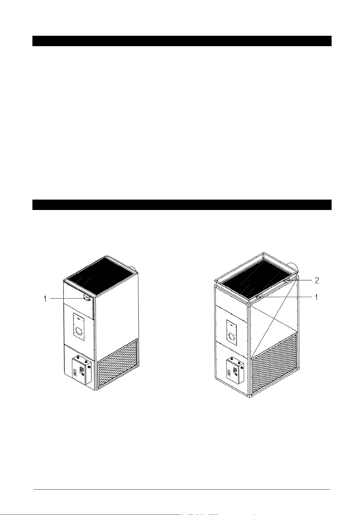
POSITIONING OF FAN, LIMIT AND SAFETY THERMOSTATS
POSITIONING
Equipments Typ 1÷10, will be delivered with the thermostat(s) still moounted in the right position.
Typ 1÷4 Typ 5÷10
Contents:
1. Bi-thermostat (FAN – LM):
FAN function connected. Setting ( by manufacturer ) 25–35°C;
LIMIT function connected. Setting ( by manufacturer ) 100°C.
2. Bi-thermostat (TR):
ONLY SAFETY function connected. Setting (by manufacturer) 80°C.
22
Page 23

The equipments typ 11 to 15 , will be delivered, due theirs possibility to be handled, in 2 separated sections. For this
reason the thermostats will be connected to the electric boards but not positioned: they need to be posit ioned during the
installation. Please follows this instructions:
Typ 11÷14
Typ 15
Contents:
1. Bi-thermostat (FAN - LM):
FAN function connected. Setting 25 – 35°C;
LIMIT function connected. Setting 100°C;
2. Bi-thermostat (TR):
ONLY SAFETY function connected. Setting (by
manufacturer) 80°C.
3. Bi-thermostat (FAN):
ONLY FAN function connected. Setting (by
manufacturer) 25-35°C;
WARNING!
The different thermostats and their positioning are
recognisable and can not be inverted thanks to a l abelling
on the thermostats and on the placements sites on the
equipment. Furthermore, the different length of their
sheathing helps.
23
Page 24

FAN-LIMIT-SAFETY THERMOSTATS SETTING
The thermostats will be supplied with the setting pointed out in the table here under:
FAN thermostat: 25 – 35°C
LIMIT (1) thermostat 100°C
SAFETY (2) thermostat Pre-setting 80°C
(1) The LIMIT thermostat have a permanent setting and do not have to be touched;
(2) The SAFETY Thermostat (Typ 515) need to be set as specified in the manual during the installation.
To control od re-set the set-point in the different thermostats, operate as hereby descripted:
Contents:
1. White automatic-manual ventilation switch (where
available).
2. FAN function electrical connections.
3. Dual thermostat graduated reading.
4. Fixture holes.
5. Fans stop temperature flag.
6. LIMIT-SAFETY intervention temperatures flag
7. Cabl e grip slits. Inserting a screwdriver the terminal is
released and it is possible to pass the wire. Removing
the end of the screwdriver the terminal locks the wire
auto matically into the terminal.
WARNING!
Pull gently on the wire to make sure it is in fact
locked in place.
8. Fan starts temperature flag.
9. LIMIT-SAFETYfunctions electrical connections.
10. Red button to release LIMIT response.
11. Metal bridge (where available).
WARNING!
For the typ 1 the metal bridge 11 must be present.
For the models from typ 2 until typ 15 the metal bridge 11
must be removed.
SAFETY THERMOSTAT SETTING (Typ 515)
The setting have to be done as follows:
Start the equipment in normal running conditions;
Make sure that the burner ist set at the right heating power;
Make sure that the air flow is correct;
As the equipments runs at full capacity, check the air temperature clos e to the TR safety thermostat sensor
(verifying the positioning of graduated rea ding), and after this set the intervention temperature at list 15-20
degrees over. For example, if the air temperature would be 40°C, then the thermostat intervention
temperature have to be 60°C.
Typ 1
Typ 215
24
Page 25

FAN START TIMER
POSITIONING
Housed inside the electrical panel in the models typ 11 to typ 14.
FUNCTION
This is connected in parallel with the FAN (FA) thermostat and
controlled by the RTZ relay with the function of ensuring the start up of
the fan assembly after a maximum time of 1 minute from the ignition of
the burner flame. The fan assembly is controlled onl y by the FAN (FA)
thermostat.
SETTING
The TZ timer is supplied electrically on the closing of the room
thermostat’s contact (TA) which coincides with the ligh-ting of the burner
flame. The stopping of the fan assembly is controlled only by the FAN
(FA) thermostat.
Owing to the different cycle times of the installed burner it is esse ntial to
carry out an adjustment of the time set on the TZ timer.
A
B
To make this adjustment proceed as follows:
1. Time with a stop-watch the time between the closing of the room thermo stat contact (TA) and the ignition of the
burner flame (time of any control test for the gas ramp seal, pre-wash time etc.).
2. Increase time by 1 minute and set it at the TZ timer, using cross cut screw after having selected a suitable scale
means of the micro-switches 1.
A: Set on value 10;
B: Set on 0,1min.
WARNING!
When the setting has been carried out run complete cycle of the g enerator ignition sequ ence and mak e sure that the fan
does in fact come on 1 minute maximum from the ignition of the burner flame.
SETTINGS
BURNERS MATCHING TABLE
The burners which can be matched for the best performance of the generators are as follows:
RIELLO Oil burners:
Typ Burner model Electrical supply
1 R40 G5
RG 2
2 R40 G10
RG 2
3 R40 G10
RG 2
4 R40 G20
RG 3
5 R40 G20
RG 3
6 R40 G20
RG 4S
7 R40 G20S
RG 4S
8 RL 28 tc
RL 28/1 tc
RG 5S
9 RL 28 tc
230V 50Hz
230V 50Hz
230V 50Hz
230V 50Hz
230V 50Hz
230V 50Hz
230V 50Hz
230V 50Hz
230V 50Hz
230V 50Hz
230V 50Hz
230V 50Hz
230V 50Hz
230V 50Hz
230V 50Hz
230V 50Hz
230V 50Hz
230V 50Hz
25
Page 26

RL 28/1 tc
RL 34/1 MZ tc
10 RL 38 tc
RL 34/1 MZ tc
11 RL 50 tc
RL 44 MZ tc
12 RL 50 tc
13 RL 70 tc
14 RL 70 tc
15 RL 100 tc
230V 50Hz
230V 50Hz
230V 50Hz
230V 50Hz
400V 50Hz 3N
400V 50Hz 3N
400V 50Hz 3N
400V 50Hz 3N
400V 50Hz 3N
400V 50Hz 3N
OIL-FIRED BURNER SETTING
The assembly and adjustment of the oil-fired burner must be carried out by authorised personnel strictly following the
burner’s own instruction booklet.
26
Page 27

FAN SPEED SET-UP
The equipment is supplied as standard with the transmission ratio adjusted in such a way that the nominal air flow can be
obtained with plenum diffusion through three or four of its sides and with air intake from one or t wo sides through the
intake grills.
WARNING!
Air diffusion from one side only of the plenum is not allowed.
For any usage other then the above mentioned normal working, inv olving the diffusion of channel led air, the insertion of
filter and so on, i.e. any arrangement which cause variations in the air resistance, it is essential to carry out a check on
the air flow and regulate it, if necessary, so that it is at the nominal levels.
This check can be carried out with precise instruments or for a good rough approximation, by checking the thermal jump
between the air delivery and air intake when the burner is set at its nominal thermal capacity. The result should be
checked against the data indicated in the paragraph TECHNICAL DATA.
It is in any case necessary to check that the direction of rotation of the fans is the same as that of the arrow on the screw.
To alter the direction of rotation, in the case of a three phase electric motor, just invert one phase of the supply line
without interfering with the electrical panel. It is also nece ssary to check that the motor output does not exceed that
indicated on the plate; if necessary change the fan rpm to obtain this result.
To change the fan rpm proceed as follows:
TYP 14
Loosen screws 2 to slacken the belts;
Remove belt 1;
Slacken the dowels 4 of the moving part of the pulley 3 with a hexagonal wrench 5;
Turn the mobile part of the pulley so as to obtain the desired pitch line diameter;
Tighten the dowels hard 4 at the hollow in the boss;
Mount and tighten the belt 1.
Ty
p 510
Loosen screw 1 to slacken the belts;
Remove belt 5;
Slacken the dowels 3 of the moving part of the pulley 4 with a hexagonal wrench 2;
Turn the mobile part of the pulley so as to obtain the desired pitch line diameter;
Tighten the dowels hard 3 at the hollow in the boss;
Mount and tighten the belt 5.
WARNING!
Never stretch the belts too tight as the fan shaft could bre ak. Hand pressu re on the belt s hould be ab le to move it
by 20-30 mm.
Increasing the pitch line diameter of the pulley motor increases the fan rpm and the motor’s electrical absorption.
Reducing the pitch line diameter of the pulley motor increases the fan rpm and the motor’s electrical absorption.
The equipments typ 1115 are provided with a fixed gearing transmission and to change the rpm of the fan the
exchange of a poulley is needed.
Typ 14 Typ 510
27
Page 28
CHECKS
To ensure the proper working of the equipment it is necessary certain basic parameters must be checked. Switch the
equipment on and carry out the following:
Check that the fan assembly starts up about 1 minute after the burner runs.
When the generator is up to temperature and working normall y (after ab out 20 minutes of continuo us working), carry out
the following operations:
Check there are no leaks of combustible materials.
Check the fuel pressure, using the meter (where possible).
Check that the fumes temperature is that given in the paragraph TECHNICAL DATA, with a tolerance of +/ - 10°C.
Check the setting of the dual thermostat is that indicated in the chapter TECHNICAL DATA.
Check the graduated reading on the dual thermostat indicates 50-60°C and that the LIMIT function is not triggered.
Check that the thermal jump corresponds to that indicated in the chapter TECHNICAL DATA, with tolerance of ±5°C.
Turn the dual thermostat’s dial manually to simulate the intervention of the LIMIT thermostat and check that the
burner is in fact switched off.
Open the room thermostat’s contact and check that it acts only on the burner and does not also cause the fan
assembly to stop.
Check the motor absorption does not exceed that indicated on the plate.
Check the thermal safety relay is set at the motor absorption value.
Check that the fan runs 4 minutes longer after the turn off of the burner, before to stop.
Check that the intervention temperatur e of the safety fan is 15-20 °C over the air temperature close to the sensor of
the safety fan.
It is compulsory to check that no condensation will appare into the heat exchanger durino the runnin g. Fot this
ckeck, after ½ Hour of running turn the burner off, and check both through the chimney connection and the
smokes pipes the absence of humidity into the smokes collector and exhausts pipes.
CONTROLS
HEATING-STOP-VENTILATION SWITCH
This is located on the equipment’s electrical panel and its function is select the working cycle:
When set at the ‘heating’ symbol it programs the equipment so that the fan and burner function automatically
according to the demands for heat.
When set at ‘fan’ it controls the equipment excluding the burner. Only the fan is active providing summer ventilation.
When set at ‘stop’ it stops the hot air generator. The fan works for a certain tim e to use up the heat accumulated in
the heat exchanger.
ROOM THERMOSTAT
To be installed about 1.5 m above ground and in an area sheltered from hot or cold air currents. It controls the switching
on and off of the equipment to maintain the temperature at the set level. It must be requested as an accessory additional
to the standard delivery.
BURNER RESET BUTTON
Located on the burner itself, its function is to reset the burner when it gets locked off.
LIMIT THERMOSTAT RESET BUTTON
A red button on the FAN-LIMIT dual thermostat with the function of resetting the burner after a overheating lock.
FAN MOTOR THERMICAL PROTECTION RESET BUTTON
Located into the control box, on the thermic relais block, needs to restart the fan functioning after a block for
malfunctioning or exceeding electrical absorbance by the fan motor.
WARNING!
Before any resetting it is essential to find and remove th e cause of the safety system being triggered. If in any do ubt call
the nearest authorised technical assistance centre which will give you any assistance you require.
28
Page 29

INDICATORS
VOLTAGE ON INDICATOR
Located on the electrical panels of the types 1115 models. It is an orange light which comes on when there is voltage.
BURNER LOCKED INDICATOR
This red button is located on the burner and lights up when the burner is locked. It is also the reset button.
SAFETY STOP BUTTON
This red button is located on the electrical panel of the Types 1115 models and lights up in the following cases:
LIMIT thermostat triggered;
Fan motor thermal safety triggered.
FAN MOTOR ABSORPTION
FAN MOTOR ELECTRICAL ABSORPTION MEASUREMENT
To check the motor absorption proceed as follows:
1. Insert ammeter in one phase of the mains supply;
2. Set the equipment at summer ventilation, so as to cut out all other parts (burner and auxiliaries);
3. Take the ammeter reading for the electrical absorption a nd check against the details on the motor’s plate, als o given
in the paragraph TECHNICAL DATA.
If it is necessary to check the absorption reading after the remote co ntrol switch or the remote starter, proceed as
follows:
1. Insert the ammeter in a phase of the motor’s supply after the remote control switch or the remote starter;
2. Set the equipment at summer ventilation, so as to cut out all other parts (burner and auxiliaries);
3. Take the ammeter reading for the electrical absorption a nd check against the details on the motor’s plate, als o given
in the paragraph TECHNICAL DATA.
If the case of equipment with direct start up (typ 210) the absorption measured corresponds to that of the li ne an d must
be checked on the data on the motor plate and given in the paragraph TECHNICAL DATA.
If the case of equipment with star/Y reduced tension start up (typ 1115), the absorption measured c orresponds to that
of the phase and, divided by 1.73, must be checked against the data on the motor plate and given in the par agraph
TECHNICAL DATA.
WORKING CYCLE
VENTILATION CYCLE
This cycle works in accordance with the following stages:
Give power to the equipment;
Set the main switch on posiotion “ventilation”;
The fan assembly only now works and intake temperature re air is directed into the room.
HEATING CYCLE
This cycle works in accordance with the following stages:
Give power to the equipment;
Set the main switch on posiotion “heating”;
Set room thermostat to the desired temperature;
The burner is now given electrical supply and, after the combustion chamber pre-wash function, the flame is ignited;
After about 1 minute the fan runs and hot air is delivered into the room.
When the temperature set at the thermostat has been reached the burner stops and after about 2 to 3 minutes the fan
also stops. The whole cycle is repeated when the temperature in the room falls below the set value.
29
Page 30
START UP AND STOP
START UP
Follow the instructions in the chapter WORKING CYCLE.
STOP
To stop the equipment it is necessary follow the procedure below:
Set the room thermostat at ‘no frost’ or set the switch at “STOP”;
Wait for the fan to stop and then, if necessary, switch off the mains supply.
WARNING!
Never stop the generator by cutting off the supply at the mains as the the rmal e nergy ac cumul ated i n the heat exchanger
may trigger the LIMIT safety device resulting in the need to carry out a manual unlocking. If this is repeated there is also
a danger of dangerously overheating the heat exchanger.
MAINTENANCE
For the proper working and conservation of the equipm ent periodic maintenance and cleaning operations need to be
carried out.
Any such work must be carried out by specialised personnel which is authorised and the work should be d one when the
equipment is cold and the electrical and combustible fuel supplies cut off. All maintenanc e and c leaning oper ations which
require the use of ladders or other access means must be used with sui table and absolutely safe equipment.
AIR FILTER CLEANING
The cleaning of any intake air filter present must be periodically carried out and it is an extremely important task. If the
filter baffle is too dirty, the air flow will be reduced and cause over heating od the air and t he heat excha nger which lea ds
to the LIMIT thermostat being triggered. How often the cleaning is necessary will depend on the environment in which the
equipment is installed but as a rough guide it should be carried out on a weekly basis.
To clean the filter, proceed as follows:
Type 14 Type 515
Remove the upper panel and remove the filtrating cells
from the box.
Clean the filter cell with an air jet, vacuum cleaner or
sim ply by knocking the cell. For more complete
cleaning immerse the cell i n warm water with a neutral
detergent rinse and dry out away from sources of heat.
Remount the cell when it is perfectly dry.
30
Remove the side panel and remove the filtration cell
from the box.
Clean the filter cell with an air jet, vacuum cleaner or
sim ply by knocking the cell. For more complete
cleaning immerse the cell in warm water with a neutral
detergent rinse and dry out away from sources of heat.
Remount the cell when it is perfectly dry.
Page 31
BURNER CLEANING
The cleaning of the burner must be carried out by authorised people strictly following the burner own instructions man ual.
HEAT EXCHANGER CLEANING
The cleaning of the heat exchanger must be carried out by authorised people and is subject to specific regulations.
Generally speaking, the operation should be carried out annually at the start of each winter.
Proceed as follows:
Remove the inspection panel 1;
Remove the inspection door 2;
Remove the burner;
Only on type 14, disconnect the chimney pipe from the connector 5;
Only on type 515, remove the side panels 7 and the inspection doors 6;
Pull out any tubing 10;
Clean the tube pack 3 with a tube brush and, with a vacuum cleaner through t he burner opening 9 remove any soot
and obstructions which have been depositating in the combustion chamber 8;
Remove the soot and obstrucions depositated in t he rear fume manifold 4 using a vacuum cleaner in the chimney
connector 5 for type 14, or through the side inspection openings for type 515;
Reassemble everything taking care that the seal is good and replacing any seals if necessary.
31
Page 32

FAN MAINTENANCE
Periodically check the tightness of the transmission belts
and the alignment between the motor pulley and the fan
pulley. The belts must not be more taut than necessary to
stop them slipping; when the two sides of the belt are
pressed with the hands, it should give by at least 2-3 cm.
Adjust tightness with the belt-tightening bolts.
The bearings on type 1
loaded.
The type 11 - 12 - 13 - 1 4 - 15 (the last only on the side
opposite the transmission) have single-piece support
bearings which do not normally require grea sing but have
a grease connection.
On the transmission side in the case of type 13 - 14 there
are cast iron pedestal bearings which have to be greased
periodically with lithium soap-based grease to be
introduces after having been introduced after the pedestal
has been opened.
10 fans are also hermetic pre-
The motor bearings are hermetic, pre-loaded and hav e a
grease reservoir, which means that in normal usage the y
do not require maintenance.
LIMIT THERMOSTAT MAINTENANCE
Verify the functionality of the LIMIT dual thermostat every year by turning normally the gradu ated reading beyond the
100°C and veryfing that the burner turns off. Moreover, verify that the reset is regular by acting on the provided
unblocking button.
FUME SAMPLING POSITION
The distancese indicated below must be respected when taking samples for analyses of the equipment combustion:
ASSISTANCE
The mounting, start-up and maintenance of the hot air generators by Tecnoclima must be carried out by authorised
technicians. You may request the direct technical assistance from the nearest Manifacturer’s Assistance centre.
32
Page 33

FAULTS AND SOLUTIONS
FAULT CAUSE SOLUTIONS
THE GENERATOR
DOESN’T WORK NEITHER
IN VENTILATION NOR IN
HEATING MODE
THE GENERATOR
DOESN’T WORK IN
VENTILATION MODE
THE GENERATOR
DOESN’T WORK IN
HEATING MODE
THE OIL BURNER FLAME
TURNS ON BUT IT TURNS
OFF FEW SECONDS
LATER
No voltage
No electricity supply to tha fan
motor
No electricity supply to the oil
burner
Incorrect electrical connection
To be verified or out of order
burner
Check electrical connections
Check line fuses and auxiliaty charges wholeness
Check electrical connections
Check line fuses and auxiliary charges wholeness
Check for an eventual cut-in of the motor thermal
protection (only three-phase electricity supply
versions)
Check electrical connections
Check line fuses and auxiliary charges wholeness
Check the room thermostat positive connection
Check for an eventual cut-in of the motor thermal
protection (only three-phase electricity supply
versions)
Check for an eventual LIMIT thermostat cut-in
Check the electricity supply (phase + neutral + earth)
Check the burner setting
Replace the electronic control box of the burner
Check and/or replace the burner photocell
33
Page 34

FAULT CAUSE SOLUTIONS
THE BURNER STOPS
ANOMALOUSLY AND
CASUALLY
LIMIT THERMOSTAT CUT-IN
FAN MOTOR THERMAL
PROTECTION CUT-IN (FOR
THREE-PHASE VERSIONS)
THE FAN DOESN’T START
WITHIN ABOUT A MINUTE
LIMIT thermostat cut-in
Burner flame detached
Room thermostat incorrectly
installed
Obstruction on the air circuit
Hot air recirculation
To be verified or out of order fan
Excessive thermal power
Excessive fan motor electric
absorption and/or heating
Insufficient thermal power
Check the opening of the flow
directing fins
Check for the absence of
obstructions on air inlet grids
Check fan motor
Check the burner setting
Check that the generator doesn’t
work in a depressed room
Check that the room thermostat
sensor is not installed on the hot air
outlet
Check the opening of the flow
directing fins
Check for the absence of
obstructions on air inlet grids
Check the opening of the flow
directing fins so that it can be
excluded a hot air recirculation from
outlet to inlet
Check the air inlet temperature
Check that the fan wheel is clean
Check the fan motor efficiency
Check the state and the tension of
the belts (for three-phase versions)
Verify an eventual anomalous cut-in
of the fan motor thermal protection
(for three-phase versions)
Check the burner setting
Check that the air diffusion plenum
is mounted
Check the electricity supply voltage
Check the air inlet temperature
Check the burner setting
FROM THE STARTING OF
THE BURNER
To be verified or out of order
FAN-LIMIT dual thermostat
Check FAN index setting
Replace the FAN-LIMIT dual
thermostat
34
Page 35

FAULT CAUSE SOLUTIONS
THE FAN DOESN’T STOP
WITHIN ABOUT 4 MINUTES
FROM THE STOPPING OF
THE BURNER
THE FAN DOESN’T WORK
THE FAN RUNS
INTERMITTENTLY
THE FAN PRESENTS
FUNCTION LAPSES
THE GENERATOR GETS
ANOMALOUSLY DIRTY
INTERNAL CONDENSATION
OF THE CUMBUSTION
PRODUCTS
DIFFICULTIES TO REACH
THE TEMPERATURE SET ON
THE ROOM THERMOSTAT
Obstructed chimney
Incorrect burner setting
Incorrectly installed room thermostat
Too high room temperature
To be verified or out of order
FAN-LIMIT dual thermostat
To be verified or out of order fan
To be verified or out of order
FAN-LIMIT dual thermostat
To be verified or out of order
FAN-LIMIT dual thermostat
Insufficient thermal power
Hot air recirculation
Incorrect burner setting
Insufficient thermal power
Low thermal exchange rate due to
dirty heat exchanger
Check the air inlet temperature
Check for an eventual solar
irradiation
Check FAN index setting
Verify that the white button Is on the
AUT position
Replace the FAN-LIMIT dual
thermostat
Check the fan motor efficiency
Check the capacitor of the fan motor
(for three-phase versions)
Verify transmission belts (for threephase versions)
Verify an eventual cut-in of the fan
motor thermal protection (for threephase versions)
Check FAN index setting
Replace the FAN-LIMIT dual
thermostat
Check FAN index setting
Replace the FAN-LIMIT dual
thermostat
Check the burner setting
Check the opening of the flow
directing fins so that it can be
excluded a hot air recirculation from
outlet to inlet
Check the air inlet temperature
Check the burner setting
Clean the fumes discharge and the
chimney
Check the burner setting
Clean the heat exchanger
Check the burner setting
Check that the room thermostat
sensor is not installed on the hot air
outlet
35
Page 36

PRODUCT DISPOSAL
This product was designed and made with high qualità material and components which
can be recycled and reused.
When finding the symbol of a wheeled crossed bin on a product, be aware of the fact that
the component is covered by the European Directive 2002/96/EC.
Get informed about your local waste separation system as far as electric and electronic
products are concerned.
Respect your in force local rules and do not dispose old products with your household
waste. A correct product disposal helps preventing possible negative consequences on
human and environmental health.
NOTES
36
Page 37

EC CONFORMITY DECLARATION
DÉCLARATION DE CONFORMITÉ À LA CE
EU-ÜBEREINSTIMMUNGSERKLÄRUNG
CONFORMITEITSVERKLARINGVOOR DE EU
DICHIARAZIONE DI CONFORMITÀ
DECLARACION DE CONFORMIDAD CON LA CE
FÖRSÄKRAN OM ÖVERENSSTÄMMELSE
EU:N VAATIMUSTENMUKAISUUSVAKUUTUS
EU OVERENSSTEMMELSESERKLÆRING
EU-SAMSVAR
DEKLARACJA ZGODNOŚCI WE
ЗAЯBЛEHИE O COOTBETCTBИИ TPEБOBAHИЯМ CTAHДAPTOB EC
EC MEGFELELŐSÉGI NYILATKOZAT
PROHLÁŠENÍ O DODRŽENÍ NAŘÍZENÍ EC
EC ATITIKTIES DEKLARACIJA
EL VASTAVUSAVALDUS
EC ATBILSTĪBAS DEKLARĀCIJA
ΔΗΛΩΣΗ ΣΥΜΜΟΡΦΩΣΗΣ ΕΚ
AT UYGUNLUK BEYANI
VYHLÁSENIE ZHODY S ODPORÚČANIAMI EURÓPSKEHO SPOLOČENSTVA
DECLARAŢIA DE CONFORMITATE CU RECOMANDĂRILE COMUNITĂŢII EUROPENE
ДЕКЛАРАЦИЯ ЗА СЪОТВЕТСТВИЕ НА ЕВРОПЕЙСКАТА ОБЩНОСТ
DEKLARACIJA USKLAĐENOSTI S PREPORUKAMA EUROPSKE UNIJE
ДЕКЛАРАЦІЯ ВІДПОВІДНОСТІ EC
DESA ITALIA s.p.a. Via Tione, 12 - 37010 - Pastrengo (VR) ITALY
Portable forced air heaters: - Appareils de chauffage individuels à air forcé: - Tragbare hochdruck-heissluftturbinen: - Mobiele
ventilator-luchtverwarmer: - Generatore d’aria calda: - Calentadores móviles de aire forzado: - Portabel värmeäkt med forcerat
luftöde: - Siirrettävä kuumailmapuhallin: - Flytbare luftcirkulations apparater: - Flyttbar varmekanon: - Przenośne nagrzewnice
powietrza pod ciśnieniem: - Тепловой генератор: - Hordozható hőlégfúvók: - Přenosná topná tělesa na dm chan vzduch: - Kilnojami
aukšto slėgio oro šildytuvai: - Kaasaskantav õhusoojendi: - Pārvietojamie gaisa sildītāji ar piespiedu gaisa padevi: - Φορητη
θερμαστρα εξαναγκασμενησ ροησ αερα: - Priprava za vpihavanje toploga zraka: - Portatıf basinçli hava isiticilar: - Prenosný tlakový
teplovzdušný ohrievač: - Încălzitoare portabile de aer: - Преносими отоплители под налягане: - Uređaj za upuh toploga zraka: -
Портативні повітрянагрівачі:
BI 60 - BI 95 - BI 105 - BI 120 - BI 160 - BI 190 - BI 225 - BI 260
It is declared that these models conform to: - Ces modèles ont été déclarés conformes à:
Hiermit wird bescheinigt, daß diese Modelle in Übereinstimmung: - Hierbij wordt verklaard dat deze modellen:
Si dichiara che questi generatori sono conformi: - Se declara por este medio que estos modelos:
Ovanstående modeller överensstämmer: - Näiden mallien todistetaan täten noudattavan:
Det attesteres herved, at anførte modeller er i overensstemmelse: - Det erklæres at disse modellene er i samsvar:
Oświadcza się, że niniejsze modele zgodne są z zarządzeniem: - Hacтoящим мы зaявляем, что эти нагрeвaт
ели oтвечают
требованиям стандартов на оборудование: - Kijelentjük, hogy fenti modellek megfelelnek
Prohlašujeme, že tyto modely odpovídají Nařízení pro stroje: - Vastab järgmistele el direktiividele ja standarditele:
Atbilst sekojošu es standartu un direktīvu prasībām: - Δηλώνεται ότι αυτά τα μοντέλα είναι σε συμμόρφωση με την οδηγία περί
Μηχανημάτων: - İşbu modellerin: - Potvrdzujeme, že tieto modely sú zhodné s nariadením: - Declară că modelele sunt produse
conform hotărârii: - Декларира, че горепосочените модели съответстват Директивата за: - Očituje se da su spomenuti modeli
sukladni sa uredbom: - Декларується що ці моделі відповідають:
98/37 CE, 91/368, 93/44, EMC 89/336, 92/31, 93/68, 73/23
Pastrengo, 06/04/2010
Raffaele Legnani (Managing Director)
BI 320 - BI 390 - BI 590 - BI 645 - BI 770 - BI 1000 - BI 1100
Page 38

DESA ITALIA s.p.a.
Via Tione, 12 – 37010
Pastrengo (Verona) – Italy
www.desaitalia.com
info@desaitalia.com
06/08 Ind. rev. 9 Cod. 39/D
DESA POLAND Sp. Z.o.o
ul Magazynova 5A, 62-023
Gadki, Poland
www.desapoland.pl
office@desapoland.pl
DESA HEATING
EQUIPMENT
SHANGHAI CO., LTD
Rm. 2203, 218, HengFeng Rd,
Shanghai, China, 200070
www.desa-china.com
info@desa-china.com
 Loading...