

Page 1
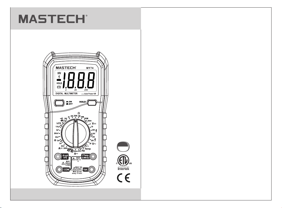
MY70/74/74B
DI GI TA L M U LT I M E T E R
OP E R A T I O N MA N U A L
CAT III
600V
Page 2

CONTENTS CONTENTS
1. General instructions
1.1 Safety information
1.1.1 Safety instructions
1.1.2 Safe working habits
1.1.3 Safety symbols
1.1.4 Safe maintenance habits
1.2 Input protection measures
2. Meter appearance description
2.1. Meter appearance
2.2 LCD display
2.3 Input socket
.......
.......................................................8
3. Operating guidance
3.1 General operation
3.1.1 Reading maintenance mode
3.2 Measuring guidance
3.2.1 Measuring AC and DC voltage
3.2.2 Measuring resistance
3.2.3 Testing diode
3.2.4 Audible continuity testing
3.2.5 Measuring capacitance (MY74,MY74B)
3.2.6 Transistor measuring
3.2.7 Measuring frequency (MY74,MY74B)
........................................1
..............................................1
............................................1
..........................................2
.................................................4
...................................5
...............................5
......................6
.............................................6
.................................................7
..........................................9
.............................................9
............................9
........................................9
..........................9
......................................10
.................................................11
...............................12
............12
.....................................13
...............13
3.2.8 Measuring temperature (MY74,MY74B)
3.2.9 Measuring current
4. Technical indicators
4.1. Comprehensive indicators
4.2. Accuracy indicators
4.2.1 DC voltage
4.2.2 AC voltage
4.2.3 Frequency (only for MY74,MY74B)
4.2.4 Resistance
4.2.5 Diode
4.2.6 Audible continuity
4.2.7 Transistor
4.2.8 Capacitance (only for MY74,MY74B)
4.2.9 Temperature (only for MY74,MY74B)
4.2.10 DC current
4.2.11 AC current
.............................................................18
5. Meter maintenance
5.1 General maintenance
5.2 Replace battery and fuse
5.3 Replacing Test L eads
5.4 Cleaning an d Dec ont ami nat ion
6. Accessories
............14
..........................................14
.......................................16
.............................16
........................................17
......................................................17
......................................................17
..................18
.....................................................18
...........................................19
.......................................................19
...............19
...............19
....................................................20
....................................................20
.........................................21
......................................21
................................21
....................................21
.................21
......................................................21
Page 3
1. General instructions
The meter is design ed and manufactured accor ding to
saf ety requi rements of EN/UL /CSA 61010-1, 61010-2-030,
610 10-2-033 on electronic measuring instrument and
han d held digital multipurpose meter. The produc t meets
wit h the requirements of 600 V CAT III and pollution
deg ree 2.
• All saf ety gui delin es outl ined sh ould be f oll ow ed, I f th e
equi pment i s used in a m anner n ot spec ified b y the
manu factu rer, the p rotec tion pr ovide d by the eq uipme nt
may be i mpair ed.
• War ning sy mbols i n the man ual ale rt user s of pote ntial
dang erous s ituat ions.
• Prec autio ns are to p reven t the use r from da magin g the
inst rumen t or the te st obje ct.
WARNING:
The sp ec ial att en tion sh ou ld be pai d wh en usin g th e
mete r be cause t he i mprop er u sage ma y ca use ele ct ric
shoc k an d damag e th e meter . Th e safet y me asure s in
comm on s afety r eg ulati on s and ope ra ting in st ructi on
shou ld b e compl ie d with wh en u sing. I n or der to ma ke
full y us e of its fu nc tions a nd e nsure s af e opera ti ons
plea se c omply w it h the usa ge i n this se ct ion car ef ully.
1.1 Safety information
1.1.1 Safety instructions
* When using this meter, the user should comply with the
following standard safety procedures:
- The safety procedures to prevent electric shock
- The safety procedures to prevent wrong use
* To ensure your safety, please use the test probe provided
with the meter. Before use, please check and make sure
that it is intact.
1.1.2 Safe working habits
* If the meter is used near a source of significant electromagnetic
interference, meter readings will become unstable and have
large errors.
* Don’t use the meter or probe when it is broken.
* If you do not use the meter in accordance with the instructions,
safety functions provided by the meter may become invalid.
* When you work around the bare conductor or bus bar, you
should be extremely careful.
* Do not use the meter near explosive gas, vapor or dust.
* Measure known voltage with meter to verify that the meter is
working properly. If the meter is working abnormally, do not use.
Protective equipment may be damaged. If there is doubt,
the meter should be sent to repair.
* The meter should be used with correct input, function and
measuring range.
* When you can’t determine the size range of signal to be tested,
please switch the measuring range to the maximum position.
* Input value can’t exceed the input limit specified in each
measuring range to prevent damage to the meter.
* When the meter is connected to the circuit being measured,
do not touch the unused input end.
* When the voltage to be tested exceeds 60Vdc or 30Vac
effective value, please operate carefully to prevent electric
shock.
* When you measure with test probe, first connect the common
testing end of black test probe to the common testing end of
circuit to be tested, then connect red test leads to the test
circuit of the test probe to the test end of circuit to be tested.
When the measurement is completed, you should first remove
the red test probe, then remove the black common test probe.
01 02
Page 4
* When use the test probe to measure, you should place your
fingers at the back of retaining ring.
* Before changing the measuring range, you must ensure that
the test probe is not connected to circuit to be tested.
* For all DC functions, including manual or automatic measuring
range, to avoid the risk of electric shock due to possible
incorrect readings, please use AC function to verify the
existence of any AC voltage. Then, select DC voltage
measuring range equal to or greater than the AC measuring
range.
* Before testing resistance, diode, capacitance measurement
or on-off states, you should first cut off power to the circuit
being tested, and discharge all high voltage capacitors.
* Don’t measure resistance or make on-off tests on a live circuit. .
* Before current measurement, you should firstly check the
meter's fuse. Before the meter is connected to the circuit
under testing,you should firstly power off the circuit to be
tested.
* When you make TV repairs or measure power conversion
circuits, you should note the high amplitude voltage pulse
of circuits being tested. The TV filter should be used to
weaken these pulses to avoid the meter damage.
* This meter uses a 9V 6F22 battery. The battery should be
properly installed in the meter’s battery compartment.
* When the battery indicator appears, the battery should be
replaced immediately. Low battery will cause meter reading
errors, and possibly result in electric shock or personal injury
* When you make type III voltage measurement, the voltage
should not exceed 600V; when you make type TV voltage
measurement, the voltage should not exceed 600V.
* When the meter shell (or part of shell) is removed, do not use
the meter.
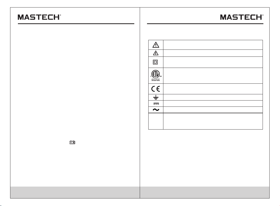
1.1. 3 Safet y symbo ls
Symbols used on the meter surface and instructions:
Note -Impo rtant s afety i nform ation , refer t o the
inst ructi on manu al.
Caut ion, po ssibi lity of e lectr ic shoc k
Equi pment p rotec ted thr ougho ut by dou ble
insu latio n or rein force d insul ation .
Co nfo r ms to UL STD . 6 101 0 -1, 6 1 010 -2-0 30,
61 010 - 2-0 33; Ce rtif ied to C SA STD. C2 2.2
NO . 6101 0-1 , 6 101 0 -2- 030, 6 1010 -2- 033
Comp lies wi th Euro pean (E U) safe ty
stan dards
Eart h (grou nd) TERMI NAL
Dire ct curr ent
Alter natin g curre nt
MEASUREMENT CATEGORY III is applicable to test
CAT III
and measuring circuits connected to the distribution
part of the building's low-voltage MAINS installation.
03 04
Page 5
1.1.4 Safe maintenance habits
* To open the meter shell or remove the battery cover, you
should first pull out the test probe.
* When performing meter maintenance, you should use
specified replacement parts.* Before opening the meter,
you should disconnect all power supplies and ensure that
you have no static electricity to avoid damaging the meter
components.
* Meter calibration, maintenance, repair and other operations
only can be performed by technicians who fully understand
the meter and electrical shock hazards.
* Before opening the meter, you should be aware that there
may be dangerous voltages remaining in some capacitances
in the meter even after powering off.
* If you find any abnormal phenomena on the meter, the meter
should be immediately turned off and repaired. Ensure that it
can not be used before passing inspection.
* When the meter is not used for a long time, please remove
the battery and avoid storing it in a high temperature and
humidity environment.
1.2 Input protection measures
* When making voltage measurements (not including 200mV
grade), the maximum input voltage is 600V DC or 600V AC.
(The maximum input voltage of 200mV grade is 250V AC or
equivalent RMS value voltage).
* When making frequency, resistance, on-off and diode
measurements, the maximum voltage is 250V AC or
equivalent RMS value voltage.
* When making capacitance, temperature, mA current, and
triode hFE measurements, the meter is protected through
a fuse (FF 400mA H 600V).
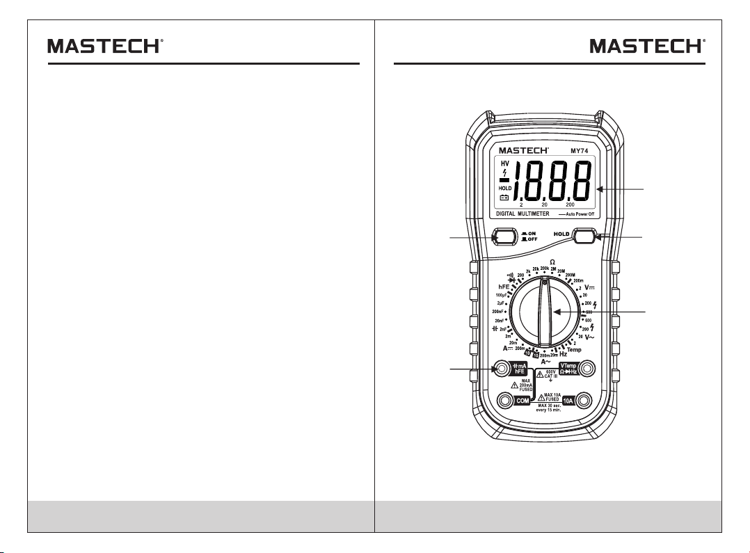
2. Meter appearance description
2.1. Meter appearance
2
5
1. LCD(liquid crystal display) 2. Mains Switch
3. HOLD Key 4. Rotary Switch 5. Input Socket
1
3
4
05 06
Page 6

2.2 LCD display
See Table 1 for information about the display.
Fig. 1 Display
Table 1 Display Symbols
Symbols
HV
HOLD
Low battery.
To avoid wrong readings causing
electric shock or personal injury,
when the low battery symbol appears,
the battery should be replaced
immediately.
Negative input polarity indication
High voltage symbol, in AC600V or DC600V.
Keep the current measurement value
Indication
2.3 Input socket
Table 2 Input Socket
Input Socket
All common input ends to be measured are
COM
VΩHz
TEMP
mA,
10A
connected with common output socket of
black test probe or dedicated multifunction
test socket.
Positive input end of voltage, resistance,
frequency, diode, buzzer measurement and
temperature test (connected with the red test
probe).
Positive input end of current mA, temperature
and triode hFE (connected with output socket
of black test probe or dedicated multifunction
test socket).
Positive input end of 10A
(connected with the red test probe).
Description
07 08
Page 7

3. Operating guidance
3.1 General operation
3.1.1 Reading maintenance mode
In reading maintenance mode, the current readings will be
kept on the display. Change the measurement function grade,
or press HOLD key to exit reading maintenance mode.
To enter and exit reading maintenance mode:
1. Press “HOLD” key, the reading will be maintained and
“ ”symbol will display on LCD display simultaneously.
2. Press “HOLD” key again to return the meter to normal
measurement state.
3.1.2 Battery saving energy function
The meter power will disconnect automatically after about
40 minutes, to save battery power.
3.2 Measuring guidance
3.2.1 Measuring AC and DC voltage
WARNING:
To prevent electrical shock and/or meter damage. Don’t
measure any RMS voltage higher than 600V DC or 600V AC
between common end and ground.
Voltage is the potential difference between two points.
AC voltage polarity changes over time, while DC voltage
polarity does not change over time.
DC voltage measuring range of this meter: 200.0mV, 2.000V,
20.00V, 200.0V and 600V; AC voltage measuring range of this
meter: 200mV (only for MY70), 2.000V, 20.00V, 200.0V and 600V.
09 10
To measure AC and DC voltage:
1. Rotate the switch to the appropriate position.
2. Respectively connect black and red test probe to COM input
socket and V input socket.
3. Measure the voltage of circuit to be tested with other two
ends of test probes. (Connected with the circuit to be tested
in parallel)
4. Read the measuring voltage value from LCD display.
When measuring DC voltage, the display will simultaneously
show the voltage polarity which is connected with red test
probe.
• Note:
In the DC 200mV and AC 2V measuring range, the meter will
have a number of displays even without input or connecting
with test probe. In this case, just make a short circuit between
“V-” and “COM”, so that the meter will display zero.
3.2.2 Measuring resistance
WARNING:
To avoid damaging meter or device to be measured, before
measuring resistance, cut off all circuits being tested and
discharge all high voltage capacitors.
Resistance is resistance force of current. The unit of resistance
is ohm ( Ω ).
Resistance range of this meter: 200.0Ω, 2.000kΩ, 20.00kΩ,
200.0kΩ, 2.000MΩ, 20.00MΩ, 200.0 MΩ.
To measure resistance:
1. Rotate switch to the appropriate position.
2. Respectively connect black and red test probe to VΩ input
socket and V input socket.
3. Measure the resistance value of circuit to be tested with
other two ends of test probes.
4. Read the measuring resistance value from LCD display.
Page 8

Here are some tips for measuring resistance:
• The resistance measured on circuit is usually different from
the rated value of resistance. This is because the test current
of the meter will flow through all possible channels between
test probes.
• When measuring low resistance, in order to accurately
measure, make a short circuit between two test probes to
read the resistance value when short circuited. This resistance
value should be subtracted after measuring the resistance to
be tested.
• At grade 20MΩ and 200 MΩ, the reading will be stable after
several seconds. A high resistance measuring is normal.
• When there is no input (for example, in an open circuit),
the display will show “1”, which means that the measured
value is out of range.
3.2.3 Testing diode
WARNING:
To avoid damaging meter or device to be measured, before
measuring diodes, cut off all circuits being tested and
discharge all high voltage capacitors.
To test diode outside circuit:
1. Rotate the switch to position.
2. Respectively connect black and red test probe to COM input
socket and input socket.
3. Respectively connect black and red test probe to negative
pole and positive pole of the diode to be tested.
4. The meter will display the forward bias voltage value of diode
being tested. If the test probe polarity is reversed, the meter
will display “1”.
In a circuit, a good diode should still produce a forward voltage
drop of 0.5V to 0.8V; but the reverse bias voltage will vary
depending on resistance values of other channels between
two test probes.
11 12
3.2.4 Audible continuity testing
WARNING:
To avoid damaging meter or device to be measured, before
testing buzzer continuity, cut off all circuits being tested and
discharge all high voltage capacitors.
To make continuity testing:
1. Rotate the switch to position.
2. Respectively connect black and red test probe to COM input
socket and input socket.
3. Measure the resistance value of circuit to be tested with other
two ends of test probes
4. During on-off testing, if the measured circuit resistance is not
greater than about 50, the buzzer will sound continuously.
3.2.5 Measuring capacitance (MY74, MY74B)
WARNING:
To avoid damaging meter or device to be measured, before
measuring capacitance, cut off all circuits being tested and
discharge all high voltage capacitors. Determine that capacitors
are discharged with DC voltage measurement function.
Capacitance range of this meter: 2.000nF, 20.00nF, 200.0nF,
2.000µF and 100.0µF.
To measure capacitance:
1. Rotate switch to the appropriate position.
2. Respectively connect black and red test probe to COM input
socket and input socket.
3. Measure the capacitance value of circuit to be tested with
other two ends of test probes and read the measuring value
from LCD display.
Here are some tips for measuring capacitance:
• When measuring bulk capacitor with this meter, readings will
stabilize after a few seconds.
Page 9

• To improve the accuracy below 2nF, subtract the distributed
capacitance of meter and cable.
3.2.6 Transistor measuring
WARNING:
To prevent electrical shock and/or meter damage. Don’t apply
any RMS voltage higher than 250V DC or AC between common
end and mA end,
1. Rotate the switch to hFE position.
2. Plug multi-function socket with correct polarity (the “+” end
of multi-function socket is connected with mA end, “COM”
end is connected with common end).
3. Determine that the transistor is NPN or PNP type, then insert
three pins of transistor to the corresponding holes of the
dedicated multi-functional socket
4. Read hFE approximation of transistor to be measured from
LCD display.
3.2.7 Measuring frequency (MY74, MY74B)
WARNING:
To prevent electrical shock and/or meter damage. Don’t
measure the frequency of RMS voltage higher than 250V DC
or AC.
To measure frequency:
1. Rotate the switch to Hz position.
2. Respectively connect black and red test probe to COM
input socket and Hz input socket.
3. Measure the frequency value of circuit to be tested with
other two ends of test probes.
4. Read the measuring frequency value from LCD display.
3.2.8 Measuring temperature (MY74, MY74B)
WARNING:
Don’t measure the surface of object with electric quantity
higher than 60V DC or 24V AC RMS, to prevent electrical
shock. Don’t measure the temperature in a microwave oven
to prevent fire or meter damage.
To measure t emperat ure:
1. Pl ug the red en d of the K-ty pe thermo couple in to the
“ ”jack an d black end i nto the“C OM”jack .
VtempΩ H z
2. Se t the rotar y switch to t he“Temp”p os ition .
3. Touch the su rface of th e object or a rea with th e
temp er ature s en sor for m ea surem en t.
4. Re ad the meas uring val ue from LCD d isplay.
3.2.9 Measuring current
WARNING:
When the ground voltage of open circuit voltage exceeds 250V,
do not try to make current measurements on the circuit. If the
fuse is blown when making a measurement, you may damage
the meter or injure yourself. To avoid damage to meter or
device, before measuring current, please check the meter's
fuse. When measuring, you must use the correct input socket,
function and measuring range. When the test probe is inserted
to the current input socket, don’t connect the other end of the
test probe with any circuit in parallel
Current range of this meter: 20μA/200μA (only for MY70)
2.000mA, 20.00mA, 200.0mA and 10.00A;
13 14
Page 10

To measure current:
1. Cut off the power supply of circuit to be tested. Discharge
all high voltage capacitors on the circuit to be tested.
2. Rotate switch to the appropriate position.
3. Connect the black test probe to the COM input socket.
If the current to be tested is lower than 200mA, connect
the red test probe to the mA input socket. If the measured
current is between the range of 200mA~10A, the red test
probe should be connected to 10A input socket.
4. Cut off the circuit to be tested. The black test probe is
connected to one end of disconnected circuit (low voltage
relatively), and the red test probe is connected to the other
end of disconnected circuit (high voltage relatively).
(Connecting test probe in reverse would make the reading
negative, but the meter won’t be damaged. )
5. Connect the power supply of circuit, then read the display
reading. If the display shows only “1”, the input is out of the
selected input range, therefore please rotate the switch to
a higher measuring range.
6. Cut off the power supply of circuit to be tested. Discharge
all high voltage capacitors. Remove the test probe of meter
and restore the circuit to its original condition.
4. Technical indicators
4.1. Comprehensive indicators
• Operating environment and condition:
600V CAT III pollution grade: 2
Elevation < 2000 m
Environment temperature and humidity:
O
0~40 C (<80% RH, <10°C, it is not to be considered).
Storage temperature and humidity:
O
0~60 C (<70% RH, remove the battery).
• Temperature coefficient: 0.1 Accuracy / C(<18 C or >28 C).
• The maximum allowable voltage between measurement end
and ground: 600V DC or 600V AC RMS
• Fuse protection:
mA grade: Fuse F1 FF 400mA H 600V;
A grade: Fuse F2 FF 10A H 600V.
• Sampling rate: about 3 times/sec.
• Maximum value display:1999. Automatically display unit
symbols in accordance with measurement function grade.
• Over-range indication: LCD will show “1”.
• Low battery indication: When the battery voltage is lower than
the normal operating voltage, “ ”will display on the LCD display.
• Input polarity indication: automatically display “ - ” symbol.
• Power supply: DC 9V
• Battery type: NEDA 1604, 6F22 or 006P.
• Outside measurement: 188 mm(L)×93 mm(W)×50mm(H).
• Weight: about 380g (include battery).
O O O
15 16
Page 11

4.2. Accuracy indicators
Accuracy: ± ( % reading + word) with one year of warranty.
Reference conditions: environmental temperature is from
18 °C to 28 °C, relative humidity is not more than 80%.
4.2.1 DC voltage
Measuring range
200mV
2V
20V
200V
600V
Resolution
0.1mV
1mV
10mV
100mV
1V
±(0.5% of reading + 2digits)
±(0.8% of reading + 2digits)
Input impedance: 10MΩ
Maximum input voltage: 600Vdc or 600Vac RMS, 250Vdc
or ac RMS with the measuring range of 200mV.
4.2.2 AC voltage
Measuring range
200mV
(only for MY70)
2V
20V
200V
600V
Resolution
0.1mV
1mV
10mV
100mV
1V
±(1.2% of reading + 3digits)
±(0.8% of reading + 3digits)
±(1.2% of reading + 3digits)
Input impedance: 10MΩ
Maximum input voltage: 600Vdc or 600V ac RMS, 250Vdc
or ac RMS with the measuring range of 200mV.
Frequency response: 40Hz-400Hz sine wave RMS
(average response)
The frequency response is 200Hz for 600V
Accuracy
Accuracy
4.2.3 Frequency (only for MY74, MY74B)
Measuring range
20kHz
Resolution
10Hz
±(2.0% of reading + 5digits)
Accuracy
Input voltage range: 200mV-10V ac RMS
Overload protection: 250V dc or 250V ac RMS
4.2.4 Resistance
Measuring range
200Ω
2kΩ
20kΩ
200kΩ
2MΩ
20MΩ
200MΩ
Resolution
0.1Ω
1Ω
10Ω
100Ω
1kΩ
10kΩ
100kΩ
±(0.8% of reading + 3digits)
±(0.8% of reading + 2digits)
±(1.0% of reading + 2digits)
±(6.0% of reading + 10digits)
Accuracy
Overload protection: 250V dc or 250V ac RMS
Open circuit voltage: below 700mV
4.2.5 Diode
Function
Diode Test
Measuring range
1V
Resolution Test environment
Test current: about 1mA.
Open circuit voltage:
0.001V
about 2.8V.
Display approximation
of diode forward voltage
drop.
Overload protection: 250V dc or 250V ac RMS
17 18
Page 12

4.2.6 Audible continuity
Function Test environment
Description
When built-in buzzer
sounds, the resistance
to be tested is not more
than 50Ω.
Test current: about 1mA.
Open circuit voltage:
about 2.8V.
4.2.7 Transistor
Measuring
range
hFE
Description
hFE approximation on
the display, (0 -1000)
Test environment
Base current 10μA
Vce is about 2.8V
Overload protection: Fuse (FF 400mA H 600V )
4.2.8 Capacitance (only for MY74, MY74B)
Measuring range
2nF
20nF
200nF
2μF
100μF
Resolution
1pF
10pF
0.1nF
1nF
100nF
±(4.0% of reading + 3digits)
±(6.0% of reading + 10digits)
Accuracy
Overload protection: Fuse (FF 400mA H 600V)
4.2.9 Temperature (only for MY74, MY74B)
Measuring range
-20°C~0°C
1°C~400°C
401°C~1000°C
Resolution
1°C
±(5.0% of reading + 4digits)
±(2.0% of reading + 3digits)
±(2.0% of reading + 5digits)
Accuracy
Temperature indicator does not include thermocouple error.
Overload protection: Fuse (FF 400mA H 600V)
4.2.10 DC current
Measuring range
20μA (for MY70, MY74B)
200μA (only for MY70)
2mA (for MY70, MY74)
20mA
200mA
10A
Resolution
0.01μA
0.1μA
1μA
10μA
0.1mA
10mA
±(2.0% of reading + 5digits)
±(0.8% of reading + 1digits)
±(1.5% of reading + 1digits)
±(2.0% of reading + 5digits)
Accuracy
Overload protection: fuse with measuring range of mA (FF400mA
H 600V); fuse with measuring range of 10A (FF10A H 600V).
Maximum input current: mA grade: 200mA DC or AC RMS;
10A grade: 10A DC or AC RMS
When measured current is greater than 10A, continuous
measurement time should not be more than 10 seconds. Stop the
current being measured after 15 minutes.
4.2.11 AC current
Measuring range
20μA
(for MY70)
200μA
(only for MY70)
2mA
(for MY70, MY74)
20mA
200mA
10A
Resolution
0.01μA
0.1μA
1μA
10μA
0.1mA
10mA
±(2.0% of reading + 5digits)
±(1.0% of reading + 5digits)
±(1.8% of reading + 5digits)
±(3.0% of reading + 7digits)
Accuracy
Overload protection: fuse with measuring range of mA (FF400mA
H 600V); fuse with measuring range of 10A (FF10A H 600V)
Maximum input current: mA grade: 200mA DC or AC RMS; 10A
grade: 10A DC or AC RMS
When measured current is greater than 10A, continuous
measurement time should not be more than 10 seconds. Stop the
current being measured after 15 minutes.
Frequency response: 40Hz-400Hz, sine wave RMS
(average response)
19 20
Page 13

5. Meter maintenance
This section provides basic maintenance information,
including instructions for replacement of fuse and battery.
Do not try to repair the meter unless you are an experienced
maintenance person with the relevant calibration, performance
testing and maintenance data
5.1 General maintenance
WARNING:
To avoid electrical shock or damage to the meter, don’t wet the
inner surfaces of the meter. Before opening shell or battery
cover, you should remove the connecting cable between the
test probe and the input signal.
Regularly clean the meter shell with damp cloth and a small
amount of detergent. Do not use abrasives or chemical solvents.
If you make input socket dirty or wet, it may affect the readings.
To clean input socket:
Turn off the meter, and pull out all test probes from the input
socket.
Remove all dirt from the socket.
Apply detergent or lubricant (such as WD-40) to a new cotton
ball.
Clean each socket with a cotton ball. Lubricant can prevent
contamination related with moisture on the socket.
5.2 Replace battery and fuse
WARNING:
To avoid electrical shock or personal injury, before opening the
battery cover to replace battery, you should turn the meter off
and make sure that the test probe is disconnected from the
measurement circuit.
To avoid wrong readings, electric shock or personal injury, when
“ ”appears on the meter display, replace the battery
immediately.
Use only a fuse with specified amperage, fusing rated value,
voltage rated value and fusing speed (F1:FF 400mA H 600V,
F2:FF 10A H 600V)
Please follow below steps to replace battery or fuse:
1. Turn off the power supply of the meter.
2. Pull out all test probes from the input socket.
3. Loosen two screws on the fixed battery cover with screwdriver.
4. Remove the battery cover.
5. Remove the old battery or damaged fuse.
6. Replace with a new battery with 9V (6F22) or a new fuse.
7. Replace the battery cover and tighten the screws.
5.3 Replacing Test L eads
If ins ul ation o n le ads is da ma ged, re pl ace it.
WARNING:
Use me et E N 61010 -0 31 stan da rd, rat ed C AT III 60 0V,
10A or b et ter tes t le ads.
5.4 Cleaning an d Dec ont ami nat ion
1. The meter can be cleaned with a soft cloth to remove any
oil, grease or grime.
2. Do not use liquid solvent or detergent.
6. Accessories
Test Leads 1set
•
Package 1pcs
•
9V Battery 1pcs
•
User's Manual 1pcs
•
21 22
Page 14

00-05-4176
 Loading...