

Page 1
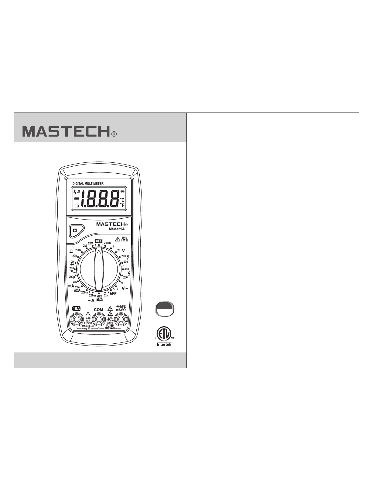
MS8 21A3
Digital Multimeter
CAT III
600V
Page 2

CONTENTS
1.1.1 Precautions.................................1
1. ............................................1Introduction
1.1.2 Safety Symbols.............................2
1.1.3 Maintenance................................3
2.Instrument Description ...........................3
2.1 Front Panel.......................................3
2.2 Display............................................5
2.3 Buttons ...........................................5
3. Specifications.........................................6
3.1 General Specifications...........................6
2.4 Rotary Switch ....................................5
2.5 Input Jacks .......................................5
2.7 Accessories ......................................5
1.1 Safety Guidelines................................1
2.6 Automatic Power Off ............................5
3.2 Tech nic al Sp eci fic ati ons .........................6
3.2.4 AC Current ..................................8
3.2.5 Resistance..................................9
3.2.6 Continuity/Diode Test......................9
3.2.1 DC Voltage..................................7
3.2.2 AC Voltage ..................................7
3.2.3 DC Current .................................8
3.2.7 hFE Transistor Gain........................9
4. Operating Instructions......................10
4.1 DC/AC Voltage..................................10
4.2 Resistance ......................................1 0
4.3 DC/AC Current ..................................11
4.4 Diodes............................................11
4.5 hFE Transistor Gain.............................12
4.6 Continuity........................................12
5. Maintenance..........................................13
5.1 Cleaning the Meter..............................13
5.2 Replacing the Probe
Replacing the Battery and Fuses
............................13
..............145.3
Page 3
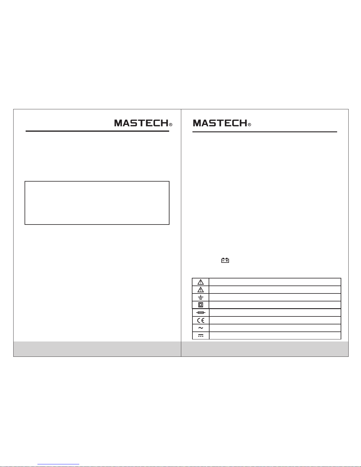
1.1.2 Safety Symbols
01
02
1.Introduction
This digital multi meter
AC/DC current, resistance, diode. The meter complies
with international safety standards UL61010-1,
CAT III 600V and pollution degree of 2.
Read all instructions carefully before using the meter and
follow all relevant safety standards.
can measure AC/DC voltage,
CSA
C22.2 No.61010-1,
• Do not perform a voltage test using the 10A input jack.
• Always be careful when working with voltages above 60V dc
or 30V ac rms. Keep fingers behind the probe barriers when
making voltage measurements.
• When connecting the test leads to a measurement circuit,
connect the common lead first, then the live lead. Reverse
when disconnecting.
• Disconnect leads from circuit before switching functions/ranges.
• Disconnect leads from circuit before testing transistors.
• Turn off power to circuit and discharge all capacitors before
making resistance, continuity or diode measurements.
• Before making current measurements, turn off power to the
circuit, break the circuit, connect the leads in series across the
break, then turn the power back on for measurement.
• When the “ ”symbol appears, replace the batteries to avoid
incorrect readings.
1.1 Safety Guidelines
To ensure safe usage of this instrument, please read the following
carefully:
1.1.1 Precautions
•
• Inspect the case before use. Check for cracks in the casing
and the insulation around the input sockets.
• Only use the test leads provided with the meter. If leads are
damaged or need to be replaced, use similar leads with
matching specifications.
• Ensure the meter works properly by testing a known voltage
source firstly. If not working properly, the protective equipment
may be damaged; have the meter serviced before using.
• Do not place meter in a strong magnetic field; this may cause
false readings.
• Do not place the meter in any environment with high pressure,
high temperature, dust, explosive gas or vapor.
All the instrument to warm up for 30 sec. before measurement.
WARNING
The special attentio n shoul d be paid when usi ng t he mete r
beca use the imp roper usa ge may cause ele ct ric sho ck a nd
dama ge t he mete r .The sa fe ty meas ures in com mon saf ety
regu latio ns a nd oper ating i ns truct ion sho ul d be comp lied wi th
when usin g. In ord er to m ake fully use of its fun ction s and
ensu re safe o perat ions pl ease co mply wi th th e usage i n thi s
sect ion car ef ully.
• Make sure the test leads are in the correct input jacks before
measurement.
• Choose the highest range when the value to be measured is
unknown beforehand.
• Never exceed the protection limit values indicated in the
specifications for each range of measurement.
Important safety information. Read the manual.
High voltage with danger.
Ground.
Double Insulation (Class II safety equipment).
Fuse m ust be re pl aced as p er the sp ec ifica tion he re in.
Acco rd with t he r elate d EU laws a nd r egula tions
AC (Al terna ti ng Curr ent)
DC (Direct Current)
Page 4

03
04
2.Instrument Description
2.1 Front Panel
1.1.3 Maintenance
• Maintenance/calibration should only be performed by
professionals.
• For continued protection against fire, replace fuse only
with the specified voltage and current ratings listed in the
manual: F1 250mA/250V and F2: 10A/600V
• Before opening the case, always disconnect test leads
from all energized circuits.
• Never use the meter unless the back cover is in place and
fastened securely.
• If any abnormality is observed, stop using the meter and
send it in for repair.
• If the meter is not going to be used for an extended period
of time, remove the batteries and avoid storing in a
hot/humid environment.
1. Display
2. Hold Button
3. Rotary Switch
4. Input Jacks
1
2
3
4
Conf orms to U L STD 6101 0-1;
Cert ified t o CS A STD C22. 2 NO.61 01 0-1
This p roduc t ha s been te sted to t he r equir ement s
of CAN /CSA C22 .2 N O.610 10-1, se cond ed ition ,
incl uding Am en dment 1 .
CAT III (MEASUREMENT CATEGORY III): It
test and measuring circuits connected to the distribution part
of the building’s low-voltage MAINS installation.
is applicable to
Page 5

When b atter y vo ltage d rops be lo w the
norm al oper at ing vol tage, “ ”w ill
appe ar on the d is play.
Pola rity In di catio n
Disp lay aut om atica lly dis pl ays “-“
Powe r
9V bat tery NE DA 16 04 or 6F2 2
Function
Range
Safe ty Rati ng
600V CAT III
Oper ating Al ti tude
<200 0m
Operating Temperature/
Humidity
0~40 °C, (<8 0% R H)
Stor age Tempera tu re/
Humi dity
-10~ 60°C, ( <7 0% RH, re move ba tt ery)
Max. I nput be tw een
term inals a nd e arth
grou nd
600V D C or AC rms
Fuse P rotec ti on
F1 250 mA/25 0V
F2 10A /600V
Samp le Rate Appr ox. 3 tim es /sec,
Disp lay
3 ½ digit LCD display,max. reading: 1999.
Over -rang e In dicat ion
disp lay sho ws “1”
Low Ba ttery I nd icati on
Temperature
coeffic ien t
0.1xaccuracy/0°C (<18°C or >28°C)
Poll ution d eg ree
2
Dime nsion s
158( L)x74 (W )x36( H) mm.
Weight
appr ox. 220 g (i nclud ing bat te ry)
05
06
2.2 Display
3 ½ digit, 15mm LCD display
2.3 Hold Button
• Press to keep the current reading on the display.
• Press the button again to return to normal display.
2.4 Rotary Switch
The rotary switch is used to switch between functions/
ranges.Functions are: voltage, current, resistance, diode,
continuity and transistor gain.
2.5 Input Jacks
•
measureme nt inpu t(red test lea d)
• COM Comm on lead input(black test lead)
• 10A: Greate r than 20 0mA current mea surement input
(red test lead)
VΩmA :voltage,resi stance,mA cur rent,diode,continu ity
:
2.6 Automatic Power O ff
After 15 min. of non -use the meter will a utomatic ally turn
itself off. To turn the meter ba ck on, move th e rotary
switch to any posi tion excep t off.
2.7 Accessoies
• Manual 1piece
• Test Leads 1pair
• Case 1piece
• Multifunction Socket 1piece
• 9V Battery 1piece
3. Specifications
3.1 General Specifications
Page 6

7
8
3.2 Technical Specifications
Accuracy: ±(% of reading + digits) at 18°C~28°C with a
relative humidity of <80%; guaranteed for a period of
one year.
Resolution
Accuracy
2V
20V
10mV
1mV
3.2.2 AC Voltage
Measuring range
±(0.8% of reading +3 digits)
3.2.1 DC Voltage
Input impedance: 10MΩ
Max. input voltage: 600V DC or AC rms.
200mV range: 250V DC or AC rms.
Resolution
Accuracy
200mV
2V
100mV
1mV
0.1mV
10mV
1V
20V
200V
600V
±(0.8% of reading +2 digits)
Measuring range
±(0.7% of reading +1 digits)
200V
600V
1V
100mV
±(1.2% of reading +3 digits)
Input Impedance: 10M
Max. Input Voltage: 600V DC or AC rms.
Frequency Response: 40Hz~400Hz rms sine wave
(avg. responding)
3.2.3 DC Current
Resolution
Accuracy
200µA
2mA
0.1mA
1µA
0.1µA
10µA
10mV
20mA
200mA
10A
±(2.0% of reading +5 digits)
Measuring range
±(1.0% of reading +3 digits)
±(1.5% of reading +1 digits)
Overload Protection: F1 250mA/250V F2 10A/600V
Max. Input Current: mA: 200mA DC or AC rms.
10A: continuous (do not exceed 15 sec.)
3.2.4 AC Current
Resolution
Accuracy
2mA
0.1mA
1µA
10µA
10mV
20mA
200mA
10A
±(3.0% of reading +10 digits)
Measuring range
±(1.2% of reading +5 digits)
±(1.8% of reading +5 digits)
Overload Protection: F1 250mA/250V F2 10A/600V
Max. Input Current: mA: 200mA DC or AC rms.
10A: continuous (do not exceed 15 sec.)
Frequency Response: 40Hz~400Hz rms sine wave
(avg. responding)
Page 7

9
10
Resolution
Accuracy
200Ω
2kΩ
100Ω
1Ω
0.1Ω
10Ω
1kΩ
20kΩ
200kΩ
2MΩ
Measuring range
±(1.0% of reading +1 digits)
Overload Protection: 250V DC or AC rms; do not exceed
15 sec. continuous measurement.
10kΩ
20MΩ
±(1.0% of reading +5 digits)
3.2.5 Resistance
±(1.0% of reading +3 digits)
Open circuit voltage:
approx. 2.8V
If measured resistance
is less than 50Ω, the
buzzer will sound.
Function
Description
3.2.6 Continuity/Diode Test
Overload Protection: 250V DC or AC rms; do not exceed
15 sec. continuous measurement.
Forward DC current:
approx. 1mA
Reverse DC voltage:
approx. 2.8V
The display shows the
approx. forward
voltage drop
3.2.7 hFE Transistor Gain
Base current: approx.
10µA
Vce: approx. 2.8V
Displays approx.
hFE transistor gain
(0-1000)
Function
Description
hFE
4. Operating Instructions
4.1 DC/AC Voltage
Warning
Max. input voltage: 600V DC or AC r ms (2 00m V
range is 250V DC or AC rms).
Do not exceed the protection limits to prevent
electric shock and/or damage to the meter.
• Turn the rotary switch to the pro pe r voltage range.
• Connect the red test lead to the V input jack and the black
test le ad to the COM jack.
• Connect the leads to the voltage source or cir cu it under test.
• Read th e measured voltage on the display.When measuring
DC volt ag e, the display will show the polarity of the red lead.
• If the display only shows “1”, it in di cates th e input exceeds
the sel ec te d range. Mo ve the rotary switch to a hig he r rang e.
4.2 Resistance
Warning
Turn of f all p owe r and d isc har ge al l capacitors
completely before making resistance
measurements.
•
• Connect the red test lead to the Ω input jack and the
black test lead to the COM jack.
• Connect the leads to the resistance or circuit under test
and read the measured resistance on the display.
• When measuring low resistances, short the test leads
and record the measurement.Then connect the leads to
the resistance to be measured and subtract the shorted
resistance.
Turn the rotary switch to th e pro per voltage range.
Page 8

11
12
Warning
Turn of f all p owe r and d isc har ge all capacitors
completely before testing diodes.
• Turn the rotary switch to the position.
• Connec t the red test lead to the input jack and the
black test lead to the COM jack.
• Connec t the red lead to the anode (+) and the black lead
to the cathode (-) of the diode.
• The meter displays the forw ard volta ge drop of the
diode. If the leads are reversed, the display will show ‘1’.
4.5 hFE Transistor Gain
Warning
To prev ent d ama ge to t he me ter, m ake s ure t he
transistor is not connected to a circuit before
making measurements.
•
• Connect the multi-function socket with the “+”end to
the hFE input jack and the “COM” end to the COM jack.
• Connect the transistor to the correct NPN or PNP slo ts
of the multi-function socket for measurement.
• Read the measured transistor gain on the display.
Turn the rotary switch to th e hFE p osi tio n.
Note:
• When the measured resistance is greater than 1MΩ,
wait a few seconds for readings to stabilize.This is
normal for high resistance measurements.
• When the circuit is open or leads not connected, the
display will show “1”.
4.3 DC/AC Current
Warning
To avoi d per son al in jur y, da mag e to th e met er or
device under test, always be sure to have the
rotary in the correct position and leads in the
correct jack before making current measurements.
• Turn the rotary switch to the proper current range.
• Connect the black test lead to the COM jack.If the
current to be measured is less than 200mA, connect the
red test lead to the mA jack; if the current to be measured
is greater than 200mA, connect the red test lead to the
10A jack.
• Break the circuit and connect the leads in series with the
circuit under test.
• Read the measured current on the display.When
measuring DC current, the display will show the polarity
of the red lead.
• If the display only shows “1”, it indicates the input
exceeds the selected range.Move the rotary switch to a
higher range.
4.4 Diodes
4.6 Continuity
Warning
Turn of f all p owe r and d isc har ge al l capacitors
completely before testing continuity.
•
• Connect the red test lead to the Ω input jack and the
black test lead to the COM jack.
• Connect the leads to the circuit under test.
• If the measured resistance is less than 50Ω, the buzzer
will sound.
Turn the rotary switch to th e pos iti on.
Page 9

13
00-05-3595
5. Maintenance
5.1 Cleaning the Meter
Warning
Before opening the back cover, turn off the meter
and disconnect test leads from any circuit.
Clean meter with a damp cloth and mild detergent; do
not use chemical solvents on the meter.Dirt or moisture
on the input jacks can aff ect t he re adi ng of t he me ter.
To clea n the i npu t jac ks:
• Turn the rotary switch to OFF and remove test leads.
• Remove all dirt from the input jacks.
• Use a detergent or lubricant with a cotton swab to clean
the jacks.Use a new cotton swab for each jack to prevent
cross contamination.
5.2 Replacing the Battery and Fuses
5.3 Replacing the Probe
1. Und er norm al c ondit ions, i t is u nnece ssary t o re place t he fuse .
Don' t repla ce i t until t he prob es a re unpl ugged a nd t he powe r is
shut d own. Take out the t wo scre ws of the rea r cover t o remove
the ho using .
2. The spe cificat ion of th e fuse is:
F1 250 mA/25 0V, F2 10A/ 600V
The repl acement s hould b e of the same s pecif ication .
3. The bat tery for th is mult imeter is 9 V NEDA 160 4 or 6F22.
The repl acement s hould b e of the same s pecif ication .
4. Don 't put th e in strum ent int o us e until t he rear c ov er is scr ewed
afte r repla ci ng batt ery or fu se .
To avoid electric shock, make sure the probes are disconnected
from the measured circuit before removing the rear cover.
Make sure the rear cover is tightly screwed before using the
instrument.
Warning
If in su lation on pro be is damaged, re place it.
Use meet EN 61010-031 standard, rated CAT III 600V, 10A or better probe.
WARNING
14
DONGGUAN HUAYI M AS TE CH C OM PAN Y LIMITED
Yuliangwei Industrial Area,Qingxi
Dongguan,Guangdong,China
http://www.p-mastech.com
 Loading...