

Page 1
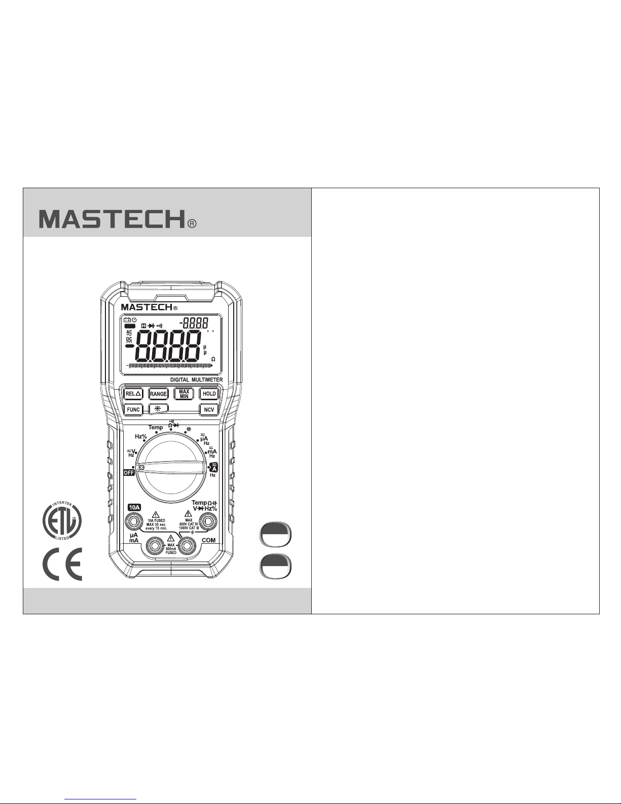
MS8251A
REL MAX MIN
%
AUTO
kHz
nmF
Hz
kM
C F
mVA
0 10 20 30 40 50 60 66
MS8251A
DIGITAL MULTIMETER
OPERATION MANUAL
CAT.III
1000 V
CAT.I V
600 V
Page 2

01 02
1. Safety Information
1.2 Use
To reduc e the risk of elect ri cal shock, prod uct damage
or per sonal injury, please f ol low the safety in structions
desc ribed in the user m an ual. read the use r manual
befo re using the mete r.
This i nstrument mee ts G B/T 13 978-92 and
GB47 93.1-2007 (IE C- 61010-1,IEC -61010-2-03 2)
stan dards for safety re quirements fo r electronic te sting
inst ruments,pol lu tion degree 2,A nd over voltage r ating
of CAT III 1000V and CAT IV 600V.
Foll ow all safety ins tr uctions to ensu re safe use of the
inst rument.Prop er u se and protecti on of the meter wil l
ensu re long life of the m et er.
1.1 Preparation
1.1. 1
-
-
1.1. 2
When u sing the meter, fo ll ow the followin g
safe ty r ules:
Alwa ys take precaut io n to prevent elec trical shock
Neve r misuse the inst ru ment
Chec k to see if the meter or an y components we re
dama ge d during shipme nt.
Chec k the meter and acc es sories thorou ghly
befo re u sing.
Insp ect test leads and pr obes for cracks , breaks or
craz es o n the insulatio n before using th e meter.
Use te st leads provid ed w ith the unit.If n ecessary,
repl ac e test leads with i dentical spec ifications.
1.1. 3
1.1. 4
1.1. 5
1.2. 1
1.2. 2
1.2. 3
1.2. 4
Turn the rotary sw it ch to the require d function and
rang e to b e measured.
When u sing the CAT Ⅳ en vi ronment, if the
meas ur ing voltage bet ween terminal s and earth
grou nd e xceeds 600V, CAT III envir onments or
volt ag e measurement b etween the term inal and
the ea rt h more than 1000V, do not measur e voltage.
Alwa ys be careful whe n wo rking with volt ages above
60V DC o r 30 V AC RMS. Keep finge rs behind the
prob e ba rriers while me asuring.Nev er touch probes
duri ng m easurement.
Choo se the highest ra ng e when the value to b e
meas ur ed is unknown.
1.2. 5 Remove test lea ds b efore switchi ng functions on
the ro ta ry switch.
1.2. 6 Do not perform re si stance, capac itance, diode a nd
cont in uity measurem ents on powered c ircuits.
1.2. 7 Never connect t he t est leads acros s a voltage
sour ce w hile the rotary s witch is in the res istance,
diod e or c ontinuity mod e. Doing so can dam age
the me te r.
1.2. 8 Po wer off the circuit and d ischarge capa citors
befo re t esting capaci tance.
1.2. 9 Do not place the me te r in any environm ent with
high p re ssure, high tem perature, dus t, explosive
gas or v ap or.
1.2. 10 Stop using the m et er if any failure o r abnormal
func ti on is observed.
1.2. 11 Do not u se m eter unless bat tery cover is in pl ace
a secu re d.
1.2. 12 Avoid dire ct sunlight, ex po sing batterie s to
humi di ty, any s trong magneti c field, or high
temp er atures to ensur e the extended li fe of the
mete r.
Warning
Page 3
03 04
1.3 Mark
Note ( Im portant safet y information . Refer to
the op er ation manual)
CAT IV
Refe rs t o the impulse wit hstand voltag e protection
leve l in accordance w it h IEC-61010-1 s tandard
over vo ltage(insta llation)cat egory IV,po llution
degr ee 2
High Vo ltage
Comp liance with req ui rements for dou ble insulatio n
(Cat egory II)
1.4 Maintenance
solv en t or detergent.
1.4. 5 Wh en the instru me nt is not in use, tur n rotary switch
to “OF F” .
1.4. 6 If t he instrument i s not to be used for an e xtended
peri od o f time, remove th e batteries to pr event
dama ge t o the instrumen t.
2. Features and Components
-
-
-
-
-
-
-
-
- .
-
- .
The MS 8251A is a portabl e, h and-held yet pr ofessional
mete r th at features an LC D with backligh t, overload
prot ec tion and low ba tt ery indicator. These m eters are
easy t o us e with one hand , su itable for prof essional
user s or a mateurs, and id eal for school or h ome use.
Func ti ons include : AC/ DC voltage, AC/D C current,
resi stance, capac it ance, continu ity, di ode test,
freq ue ncy and duty cy cl e.
Auto a nd manual range .
Auto p ower off.
Max me asurement.
Min me asurement.
Rela tive measurem en t
Read ing Hold functi on .
Average co mmutation
Simu ltaneously di sp lay frequency d uring AC voltage /
curr ent measureme nt s.
Non- contact volta ge t est
Mete r co mplies with E ur opean Communi ty (EU)
stan dards
Eart h Gr ound
2.1 Components
(1)
(2)
(3)
(4)
Non- contact volta ge d etection indi cator
LCD sc reen
Func ti on buttons
Rota ry switch
(5) In put sockets
(6) No n-contact vol ta ge sensor
1.4. 1 To avoid e lectric shock o r pe rsonal injury, repai rs
or ser vi cing not covere d in this manual sh ould be
perf or med only by quali fied personne l.
1.4. 2 Remove test lea ds b efore opening b attery cover
1.4. 3 To avoid i ncorrect read in gs causing elec tric shock
or per so nal injury,when low ba ttery symbol, “ ”
appe ar s, replace batt eries immedia tely.
1.4. 4 The me te r can be cleane d wi th a soft cloth to
remo ve a ny oil, grease or g rime. Do not use li quid
CAT III R ef ers to the impuls e withstand vol tage
prot ec tion level in acc ordance with IE C-61010-1
stan dard overvolt ag e(installat ion) category I II,
poll ut ion degree 2
Comp lies with U.S. an d Ca nadian safety s tandards
Page 4

05 0 6
2.2 Buttons and Sy mbols
HOLD button: hold cu rr ent reading on sc reen.
FUNC b utton: switch b et ween function s.
RANG E button: switch be tween auto/ma nual ranges.
REL bu tton: relativ e re ading
MAX/ MI N button: switc h between maxim um/ minimum
read ings.
b
OFF po si tion:
COM
utto n: turn on/off backligh t.
EMP po si tion: thermoc ouple tempera ture measurem ent.
turn o ff met er.
Temp V Hz% jack :v oltage, curre nt, resistanc e,
capa citance, diod e, c ontinuity, frequen cy, dut y cycle,
temp erature input t er minal.
jack : co mmon input te rm inal.
µAmA jack: curre nt m easurements < 600mA.
10A jack: curren t me asurements >6 00mA to 10A.
2.3 LCD display
REL MAX MIN
%
AUTO
kHz
nmF
Hz
kM
C F
mVA
0 10 20 30 40 50 60 66
2
3
4
5
6
1
MS8251A
REL MAX MIN
%
AUTO
kHz
nmF
Hz
kM
C F
mVA
0 10 20 30 40 50 60 66
Page 5

07 0 8
Alte rnating curre nt
Dire ct current
Diod e
Cont inuity
Auto ranging mode
Maxi mum value
Mini mum value
Low ba ttery
Perc entage (duty cy cl e)
Hert z, Kilohertz (fre quency)
Mill ivolt, Volt (vol ta ge)
Micr o amp, Milliamp , Amp ( current)
Nano farad, Microf ar ad, Millifara d
(cap acitance)
Ohm, K il ohm, Megaoh m (r esistance)
Rela tive value
AUTO
MAX
MIN
%
Hz, kH z
mV, V
REL
Ω, kΩ, M Ω
nF, μF, mF
μA, mA , A
Auto p ower off
NCV
Non- contact volta ge d etection
Data h old
3.1 General Specifications
3.1.1 Manual and auto range
3.1.2 Full range overload protection
3.1.3The maximum voltage allowed between the measuring
end and the earth:CAT IV measurement environment
for 600V DC or AC(RMS),CAT III measurement
environment for 1000VDC or AC(RMS).
3.1.4 Maximum working height: 2000m
3.1.4 Maximum working height: 2000m
3.1.5 Display:LCD
3.1.6 Maximum display value:6599
3.1.7 Polarity indication:“-” indicates negativepolarity
3.1.8 Overload indication:“0L” or “-0L”
3.1.9 Sampling frequency: 0.4s (digital display)/ 0.04s
(bar graph).For current readings, 1s (digital display)
/ 0.1s (bar graph)
3.1.10 Units display: functions and units
3.1.11 Auto power off: 15 minutes
3.1.12 Power supply: 9V 6F22 battery
3.1.13 Low battery indication: LCD displays“ ”
3.1.14 Temperature coefficient: less than 0.1x specified
accuracy/°C
3.1.15 Operating temperature:0°C ~40°C
3.1.16 Storage temperature:-10°C ~50°C
3.1.17 Dimensions:175×85×52mm
3.1.18 Weight:approx.420g(including battery)
3. Specifications
The Me te r should be cal ib rated annuall y between
18°C ~28°C and a relat iv e humidity less t han 75%.
Page 6

09 1 0
3.2.3 DC Volta ge
3.2 Technica l Specifications
3.2. 1 average value C ha racteristic s
Average re sponse digita l mu ltimeter, when t he input a
pure s ine wave, you can a cc urately measu re the rms of
sine w ave, but the non- si nusoidal RMS me asurement is
not pr ecise enough.
3.2. 2 Im pedance Chara cteristics
Norm al impedance( 10 M) with normal te sting capabil ities.
Ghos t vo ltage can occ ur w hen power suppl y
- Inpu t im pedance: 10 MΩ
- Over lo ad protecti on : 660mV range: 25 0V DC or AC
(RMS ), 6.6V-1000V r an ge: 1000V DC/AC ( RMS)
- Maxi mum input volta ge : 1000V DC
0.1mV
±(0.8% of reading + 3 digits)
660mV
0.001V
0.01V
0.1V
1V
6.6V
66V
660V
1000V
±(0.5% reading + 5 digits)of
Reso lution Accuracy
rang e
±(0.8% reading + 3 digits)of
3.2.4 AC Voltage
Frequency Range
40 ~ 60H z
40 ~40 0Hz
40 ~ 400 Hz
- Inpu t im pedance: 10 MΩ
- Over lo ad protecti on : 660mV range: 25 0V DC or AC
(RMS ), 6.6V-1000V r an ge: 1000V DC/AC ( RMS)
- Maxi mum input volta ge : 1000V AC (RMS)
- Resp onse: Average, calib ra ted in rms of sine wa ve.
0.1mV
±(1.5% reading
+ 5 digits)
of
660mV
0.001V
0.01V
0.1V
6.6V
66V
660V
±(1.2% reading
+ 5 digits)
of
Resolution Accu racy
rang e
±(1.0% reading
+ 3 digits)
of
3.2. 5 Resistance
- Open c ircuit voltag e: 1.0V
- Over lo ad protecti on : 250V DC /AC (RMS)
appr ox.
0.1Ω660Ω
0.001kΩ
0.01kΩ
0.1kΩ
6.6kΩ
66kΩ
660kΩ
6.6MΩ
±(0.8% of reading + 5 digits)
±(1.5% reading + 5 digits)of
66MΩ 0.1MΩ
0.001MΩ
Reso lution
Accu racy
rang e
1V
1000V
Page 7

3.2. 6 Capacitance
- Over lo ad protecti on : 250V DC or AC (RMS)
0.001nF6.6nF
0.01nF
0.001µF
0.01µF
66nF
6.6µF
66µF
660µF
±(3.0% reading + 3 digits)
0.1µF
Reso lution
Accu racy
rang e
0.1nF660nF
0.001mF6.6mF
66mF 0.01mF
±(4.0% reading + 5 digits)
±(4.0% reading + 5 digits)
11 12
3.2. 7 Diode Tes t
- Forw ard DC current : 1mA
-
approx.
Reve rs DC voltage: ap pr ox. 3.2V
- Over load protecti on :250V DC/AC(r ms)
Show s approximate f or ward
volt age of diode
0.001V
Reso lution F unction
rang e
3.2. 8 Continuity
- Open c ircuit voltag e: a pprox. 1.0V
- Over lo ad protecti on :250V DC/AC(r ms)
If mea su red resistanc e is
less t han 50Ω, a buzzer wil l
soun d
0.1Ω
Reso lution Fun ct ion
rang e
- :
- : >
Rang e 10Hz~10 kH z
Inpu t Voltage 0 .2 V AC (Input voltag e should increa se
alon g with the freque nc y)
3.2. 9 Fr equency
3.2. 9.1 Frequency (V po sition):
66Hz
±(1.5% reading + 5 digits)
660H z
6.6k Hz
10kH z
0.01Hz
0.1Hz
0.001kHz
0.01kHz
Reso lution
Accu racy
rang e
66Hz
±(1.5% reading + 5 digits)
660H z
660k Hz
6.6M Hz
0.01Hz
0.1Hz
0.1kHz
1kHz
Reso lution
Accu racy
rang e
3.2. 9.2 Frequency (Hz p osition):
66MH z 10kHz
6.6k Hz
66kH z
0.001kHz
0.01kHz
±(1.5% reading + 5 digits)
- Over lo ad protecti on :250V DC/AC(r ms)
- Inpu t Voltage:3V pea k to p eak AC
1-99 %
±2.0%
0.1%
Reso lution
Accu racy
rang e
3.2. 9.3 Duty Cycle
Page 8

13 14
660µA
±(1.5% reading + 5 digits)
66mA
10A
0.1µA
1µA
10µA
10mA
±(3.0% reading + 5 digits)
6600µA
660mA
100µA
Reso lution
Accu racy
rang e
3.2. 11 AC Current
Over load protecti on :
µA and mA gr ade: Fuse FF600 mA /1000V,
A : Fuse F F1 0A/1000V.
- Freq uency range: 40 ~ 4 00 Hz
posi tion
- Resp onse: Average, calib ra ted in rms of sine wa ve.
When t he target curre nt i s larger than 5A, d o not continue
meas urement for mor e th an 10 sec. Pause fo r 1 minute
afte r th e measuring .
3.2. 10 DC Current
Over load protecti on :
µA and mA : F use FF600mA/1 00 0V,
: Fuse F F1 0A/1000V.
posi tion
A posit ion
When t he target curre nt i s larger than 5A, d o not continue
meas urement for mor e th an 10 sec. Pause fo r 1 minute
afte r th e measuring .
660 Aµ
±(1.0% reading + 5 digits)
66mA
10A
0.1µA
1µA
10µA
10mA
±(2.0% reading + 5 digits)
6600 Aµ
660mA
100µA
Reso lution
Accu racy
rang e
3.2. 12 Temp er ature
4. Using the Meter
4.1 Da ta Hold
4.2. 1
Note :
In vol ta ge, current , re sistance and ca pacitance
mode s, t he default rang e is “AUTO”
4.2. 2 Pr ess “RANGE” to en ter manual rang ing.Each
pres s sw itches to a highe r range.Press ing the
butt on a t the highest ran ge will return to t he lowest
rang e.
4.2. 3 Hold “RANGE” to r et urn to “AUTO”
4.2. 4 Pr essing “RAN GE ” in Max/Min mode w ill return the
mete r to n ormal reading .
Manu al range is disab le d in frequency mo de.
4.2 Ma nu al Range
4.1. 1 During a measur em ent, press the “H OLD” button
once t o ho ld the reading.
4.1. 2 Pr ess “HOLD” agai n to release the ho ld.
4.3 Relative Measurement
4.3. 1
will s to re the reading wh en pressed and di splay the
differen ce b etween curren t reading and the s tored
read in g.
4.3. 2 Pr ess “REL ” again to retur n to normal.
Pres s “REL to en ter relative me asurement. This
Rang e Inpu t Test Range Accuracy
Ambient Temp
±2 dig its
±4 dig its
±5 dig its
±4 dig its
±20 di gits
0~10 00°C
400° C
1000 °C
800° F
1800 °F
32~1832°F
±(1.0% of reading
+3 digits)
Ambient Temp
±2 dig its
Page 9

15 1 6
4.4. 1 Pr ess “MAX/MIN” t o display the max imum value
reco rd ed
4.4. 2 Pr ess “MAX/MIN” a gain to display t he minimum
valu e re corded.
4.4. 3 Hold “MAX/MIN ” to r eturn to normal r eadings.
4.4 Ma ximum/Minimum R eading
4.5 Fu nc tion Switchin g
4.6 Backlight
4.7 Auto Power of f
4.8 No n- Contact Voltage (NCV )
4.7. 1 If t here is no operat ion for 15 minute s after turning
the ma ch ine on, the meter w ill automatic ally power
off to save th e ba ttery.
4.7. 2 After automati c po wer-off, press any ke y to turn the
mete r on a gain.
4.7. 3 Holding the "FU NC " key when poweri ng on will
canc el a utomatic powe r-off function.
4.8. 1 Wi th the rotary swi tch in any positi on except OFF,
hold d ow n the “NCV” butto n.
4.8. 2 Mo ve the tip of the met er near the volta ge source
or con du ctor. If the volta ge detected is gr eater
than 110VAC, the buzze r will beep and the N CV
indi ca tor near the tip of t he meter will fla sh.
4.5. 1 In v oltage or cur re nt modes, press “ FUNC” to
swit ch b etween AC and DC.
4.5. 2 In r esistance , di ode or continui ty modes, press
“FUN C” t o switch betwee n measurement s.
4.5. 3 In t emperature mo de, press “FUNC ” to switch
betw ee n °C and °F.
4.6. 1 Pr ess “ ”to turn on bac klight.Pres s again to turn off.
Note :
1.Ev en though there i s no i ndication,v oltage may stil l
exis t. Do not rely solel y on NCV detector t o determine
the pr es ence of voltage i n a wire.The meas urement
may be a ffec te d by the design of th e outlet,type o f
insu lation and othe r ex ternal factor s.
2.Th e vo ltage sensi ng i ndicator may tu rn on when a
volt ag e is fed to the meter.
3.Ot he r external in te rference(ex .Flashlight ,motor)may
trig ger the NCV senso r.
4.9 AC/DC Voltage
Volta ge is the electri ca l potential differe nce between two
poin ts in a circuit. AC po la rity changes ov er time, where
DC pol arity stays con st ant.
Meas uring AC or DC volta ge :
4.9. 1 Mo ve the rotary swi tch to the “V” posi tion.
4.9. 2 Connect the red tes t lead to the “V” jac k and the
blac k te st lead to the “COM ” jack.
4.9. 3 Connect the test le ads to the voltag e source or load.
4.9. 4 The me as ured voltag e wi ll be displayed .For DC
volt ag e, polarity of th e red test lead wil l be
indi ca ted.
4.9. 5 Press “FUNC” to swi tch between AC/D C voltage.
4.10 R esistance
Ω
4.10 .1 Move the rotar y sw itch to the “ posi ti on.
4.10 .2 Connect the re d te st lead to the “Ω” ja ck and the
blac k te st lead to the “COM ” jack.
4.10 .3 Connect the te st l eads to the circu it.
4.10 .4 Resistance v al ue will be displa yed.
”
Page 10

17 1 8
4.11 Co ntinuity
4.11.1 In res is tance mode, pre ss “FUNC” to swit ch to
cont in uity mode.
4.11.2 Conn ec t the red test lead t o the input jack an d the
blac k te st lead to the “COM ” jack.
4.11.3 Conn ec t the test leads to t he circuit.
4.11.4 If the r es istance of the ci rcuit is less tha n 50Ω, a
buzz er w ill sound.
4.12 D iode
4.12 .1 In continuit y mo de, press “FUNC ” to switch to
diod e mo de.
4.12 .2 Connect the re d te st lead to the inpu t jack and the
blac k te st lead to the “COM ” jack.
4.12 .3 Connect the re d te st lead to the anod e (+) and the
blac k le ad to the cathode ( -) of the diode.
4.12 .4 The m et er will displ ay t he forward bias ed voltage
drop a cr oss the diode.
4.13 C apacitance
4.13 .1 Move the rotar y sw itch to the “
4.13 .2 Connect the re d te st lead to the inpu t jack and the
blac k te st lead to the “COM ” jack.
4.13 .3 Connect the te st l eads to the circu it/capacito r.
4.13 .4 Capacitanc e va lue will be displ ayed.
”pos ition.
4.14 F requency and Duty C ycle
4.14 .1 Move the rotar y sw itch to the “Hz%” p osition.
4.14 .2 Connect the re d te st lead to the inpu t jack and the
blac k te st lead to the “COM ” jack.
4.14 .3 Connect the te st l eads to the circu it.
4.14 .4 The m ea sured frequ en cy and duty cycle w ill be
disp la yed simultane ously.
4.15 Current
4.15 .1 Remove power t o th e circuit and dis charge all
capa ci tance.
4.15 .2 Move the rotar y sw itch to the appro priate positi on
(µA, m A or A).
4.15 .3 Connect the bl ac k test lead to the “C OM” jack.
If the cur rent to be measur ed is <600mA, con nect
the re d te st lead to the “µAm A” jack.If the cu rrent
to be me as ured is >600mA, c onnect the red te st
lead t o th e “10A” jack.
4.15 .4 Break the circ ui t.Connect the t est leads acros s
the br ea k, with the red lea d to the higher vol tage
side , an d the black lead to t he lower voltag e side.
4.15 .5 Power on the cir cu it and the curren t value will be
disp la yed.If “OL” app ears on the displ ay, it me ans
the cu rr ent exceeds the s elected mode. Move the
rota ry s witch to the next h igher positio n.
5. Maintenance
5.1 Re place Battery
To avoid e lectrical sho ck , damage or perso nal injury,
remo ve test leads bef or e openning batt ery cover.
5.1. 1 “ ”
. .
Note :
If the l ow b attery symbol appe ars, the batter y
need s to b e changed.
5 1 2 Uns crew the batter y cover from the ba ck o f the
mete r an d remove the old ba ttery.
5.1. 3 In sert a new batter y and replace the c over and
tigh te n it to the meter.
Be sur e to n ote the battery p olarity when re placing.
Warning
Page 11

19
NCV
5.2 Test Lead R ep lacement
Repl ace the test lead s wi th identical or c ompatible
lead s.lead spec:1 00 0V 10A.
Repl ace test leads if l ea ds become worn.
6. Accessories
Warning
1.Test L eads 1 pair
2.Ma nual 1 pc
3.Ba tt ery 9V 6F22
4.mu ltifunction al t est socket 1pc
5.el ectromagnet ic p endant 1pc
6.K- ty pe temperatur e probe 1pc
1 pc
00-05-3589
 Loading...