

Page 1
MS8250D
DUAL DISPLAY
DIGITA L M U LT I M E T E R
User’s Manual
Page 2
Warning
01 02
1. Safety Information
Use caut io n an d follow all safety guidelines to
preven t el ec tric shock or damage to the meter.
Please r ea dy c arefully all instructions b ef or e use.
Instru me nt m eets GB/T 13 978-92 concerning digital
multim et er s tandards, along with G4B793 .1 -1 995
(IEC-6 10 10 -1,IEC-61010-2-032)sa fe ty s tandards or
electr ic al m easuring instruments with a n ov er-voltage
catego ry o f CAT IV 600V,C AT III 1000V.
Follow a ll s afety instructions to ensure sa fe u se a nd long
life of th e in st rument.
1.1 Prepara tion
1.1.1 Wh en u si ng the meter, follow all standar d sa fe ty
guidel in es :
- For univ er sa l protection again electric s ho ck .
- To preven t th e mi suse of the instrument.
1.1.2 Ch ec k th e meter for damage during trans it .
1.1.3 Test leads must be i n go od c ondition.Check the
insula ti on a nd tips before use.
1.1.4 Sa fe ty c an only be guaranteed with lead s pr ov ided.
If leads n ee d to b e replaced, they must be replac ed
with lea ds o f sa me electrical specificati on s.
1.2 Using the M eter
1.2.1 Alw ay s se t the meter to the proper functio n an d
range fi rs t.
1.2.2 Ne ve r ex ceed protection limits indi ca te d for each
measur em en t.
1.2.3 Ke ep f in gers behind the probe barrier s wh ile
measur in g.
1.2.4 Alw ay s be c areful when working with volt ag es
above 60 V DC o r 30 V AC RMS.
1.2.5 Ne ve r me asure voltages that might exc ee d 60 0V
DC/AC ab ov e ea rth ground.
1.2.6 In m an ua l range, if the circuit value is un kn ow n,
start th e me te r at the maximum range and then
adjust a cc or dingly.
1.2.7 Re mo ve t he leads from the circuit first b ef or e
switch in g be tween functions.
1.2.8 Do n ot p ow er on circuit while measuring r es istance,
capaci ta nc e, diodes and continuity.
1.2.9 Ne ve r co nnect the meter ’s l ea ds across a voltage
source w hi le t he rotary switch is in the resist an ce ,
capaci ta nc e, diode or continuity mode.
1.2.10 D o no t me asure capacitance before ca pa citors
are disc ha rg ed.
1.2.11 Do not operate t he m et er near explosive gas,
vapor or d us t.
1.2.12 S to p us ing the meter if any abnormalit y is o bs erved.
1.2.13 D o no t us e the meter unless the battery co ve r is
secure ly f as tened to the meter.
1.2.14 Avoid direct e xp os ure to sunlight to ensure
extend ed l if e of the meter.
Page 3
03 04
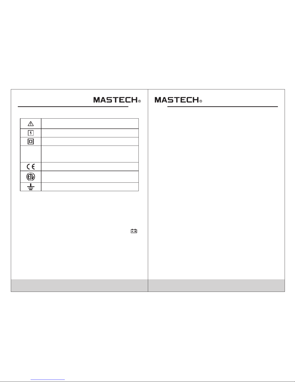
1.3 Safety Sy mbols
1.4 Mainten ance
1.4.1 To avoid electri c sh oc k or personal injury, repairs/
servic in g no t covered in this manual should b e
perfor me d on ly by qualified personnel.
1.4.2 Re mo ve t est leads from any circuit befo re o pe ning
batter y co ve r.
1.4.3 To avoid false rea di ng s that may become
danger ou s, r eplace the battery as soon as the
ymbol ap pe ar s.
1.4.4 Cl ea n th e meter using a damp cloth and mild
deterg en t on ly; do not use abrasives or chemi ca l
solven ts .
1.4.5 Alw ay s mo ve rotary switch to OFF when not us in g
the mete r.
1.4.6 If m et er i s not going to be used for an extende d
period o f ti me , remove battery to prevent damag e
to the met er.
2. Description
-The MS8 25 0D i s a portable, hand-held yet pro fe ss ional
meter th at f ea tures True RMS measurement dis pl ay,
AC/DC cur re nt , AC/DC voltage, Frequency,
Capaci ta nc e, Resistance, Continuity, Duty Ratio, D io de
Testing a nd a U SB adapter for recording read in gs o n a
PC. This Meter is easy t o us e ev en with one hand, s
uitabl e fo r pr ofessional users or amateur s, a nd i deal for
school o r ho me u se.
- Both aut o an d ma nual range.
- Displa y ho ld
- True RMS fo r AC vo lt age/current measurement s
- Relati ve m ea surement
- Maximu m me as urement
- Minimu m me as urement
- Displa y fr eq uency when measuring AC voltag e/ current
- Automat ic P ow er Off
Import an t sa fety information, please re fe r
to user’s manual
Cautio n wh en testing on live conductors
Double i ns ulation protection (categor y II )
This met er h as m et IEC61010-1 standard
with an ov er vo ltage category (600V CAT IV)
and poll ut ion degree 2.
CAT IV
Double i ns ulation protection (categor y II )
Ground
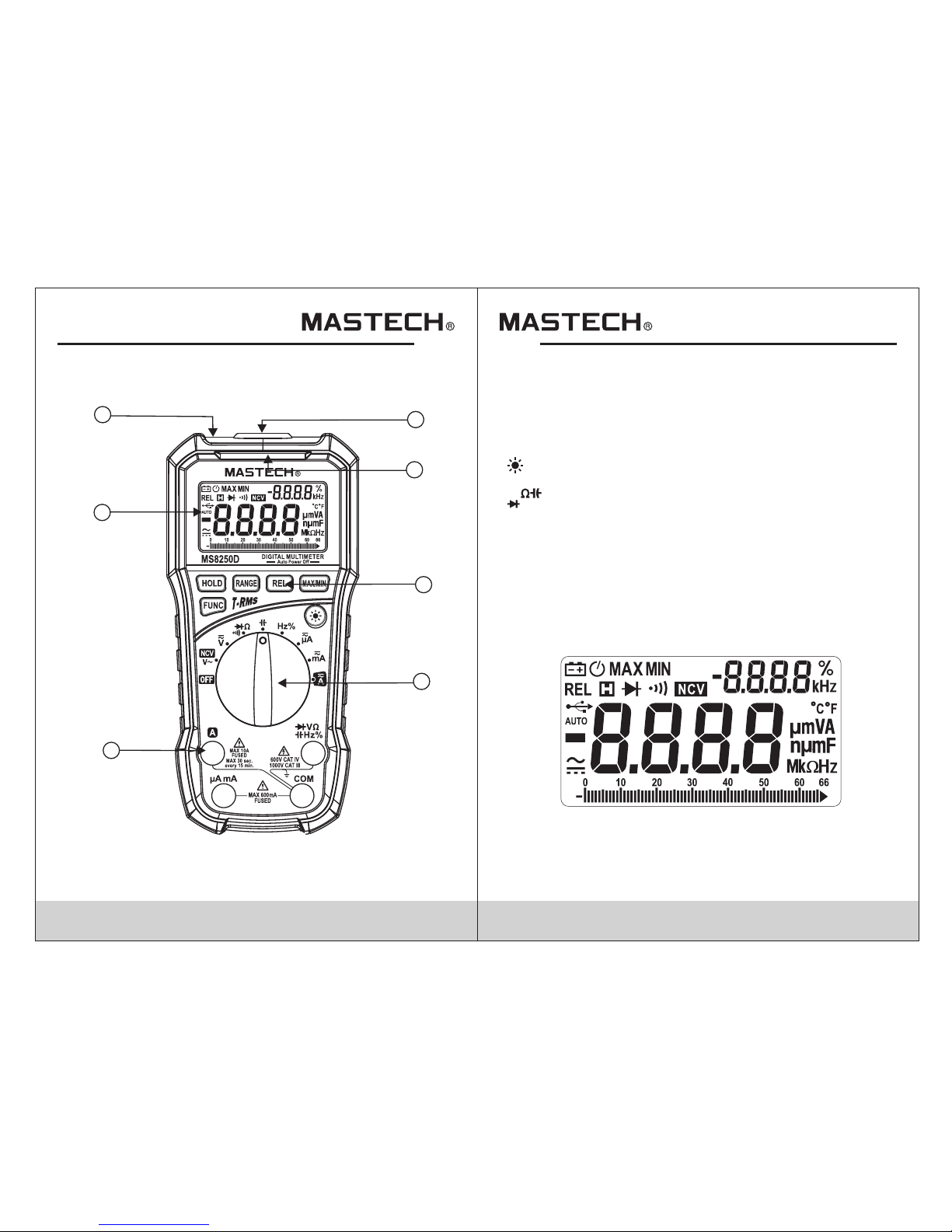
2.1 Part Name
(1)
(2)
(3)
(4)
(5)
(6)
(7)
USB inte rf ac e
NCV dete ct io n indicator
LCD disp la y
Functi on b ut tons
Rotary s wi tc h
Input so ck et s
NCV dete ct io n sensor
Compli es w ith U.S. and Canadian safety
standa rd s
Page 4
05 0 6
2.2 2 Buttons /Input jack desc ription
HOLD: ke ep c ur rent reading on the display
FUNC: sw it ch b etween functions or AC/DC meas ur ement
RANGE: s wi tc h between auto/manual range s
REL: dis pl ay r elative measurement
MAX/MI N: s wi tch between max/min measure me nt d isplay
:turn on /o ff backl ig ht
OFF:Po we r off posi ti on
:input j ac k fo r voltage, resistance, capa ci ta nce,
diode, c on ti nuity, fr eq uency and duty cycle
measur em en t
:commo n te rm inal
: input ja ck f or c urrent measurement (<660m A)
:input j ac k fo r current measurement (<10A )
COM
μAmA
10A
V
Hz%
2.3 LCD displ ay
1
2
4
5
6
3
7
Page 5

07 0 8
Altern at in g current
Direct c ur re nt
Diode
Contin ui ty
Auto ran ge
Maximu m di sp lay
Minimu m di sp lay
Low batt er y
Percen ta ge ( duty cycle)
Hertz, k il oh ertz (frequency)
Milliv ol ts , volts (voltage)
Micro am ps , mi lliamps, amps (current)
Nanofarad, microfarad, millifarad (capacitance)
Ohms, ki la oh ms, megaohms
Relati ve d isplay
AUTO
MAX
MIN
%
Hz, kHz
mV, V
REL
Ω, kΩ, MΩ
nF, μF, mF
μA, mA, A
3. Specifications
Instru me nt s hould be calibrated annuall y at 1 8°C~28°C
and rela ti ve h umidity of <75%.
NCV
Non-co nt ac t voltage detection
USB inte rf ac e active
Auto pow er o ff
3.1 General S pecifications
3.1.1 Aut o an d ma nual range
3.1.2 Fu ll r an ge overload protection
3.1.3 Ma x. v ol tage between terminal and
ground : 60 0V D C or AC rms
3.1.4 Op er at ing altitude: 2000m max.
3.1.5 Di sp la y: 6600 count LCD
3.1.6 Po la ri ty indication: automatica ll y di splays “-”
3.1.7 Ov er r an ge indication: “OL” or “-OL”
3.1.8 Sa mp le r ate: approx. 0.4s/analog ba r
graph: a pp ro x. 0.04s
except f or c ur rent measurement: approx.
1s/bar g ra ph : 0.1s
3.1.9 Un it d is play: functions and unit powe r
3.1.10 Au to p ow er off t im e: a pprox. 15 min.
3.1.11 Power supply : 9V b at tery
3.1.12 L ow b at tery indication: display sh ow s“ ”
3.1.13 Temp. coefficient: less tha n 0. 1 x accuracy/°C
3.1.14 O pe ra ting temperature: 0~40°C
3.1.15 S to ra ge temperature: -10~50°C
3.1.16 D im en sions: 180x86x52mm
3.1.17 Weight: app ro x. 2 50g (without battery)
Page 6

09 1 0
3.2 Technical Indicators
3.2.1 Tru e RM S ch aracteristics
3.2.1. 1 Fo r no n-sinusoidal signal measu re ment, the
Meter pr ov id es more accurate measuremen t th an
the trad it io nal averaging method.
3.2.1. 2 If i n AC cu rrent mode, the Meter may displ ay a
random r ea di ng between 1 and 50 when the input
is not activ e. This will n ot a ffect th e ac cu racy of
measur em en t.
3.2.1. 3 Tru e RM S requires a minimum input leve l, AC
curren t or v ol tage should be 2%~100% of the
maximu m le ve l.
3.2.2 DC Voltage
Resolu ti on
0.1mV
Accura cy
±(0.8% reading + 3 digits)of
660mV
0.001V
0.01V
0.1V
6.6V
66V
600V
±(0.5% reading + 5 digits)of
Range
- Input im pe da nce: 10M
- Overlo ad p ro tection: 660mV range: 250V DC o r AC rm s.
6.6V-10 00 V ra nges: 1000V DC or 1000V AC rms.
- Max. inp ut v ol tage: 1000V DC
Ω
0.1V1000V
3.2.3 AC Vol ta ge
Resolu ti on
0.1mV
Accura cy
±(1.5% reading + 5 digits)
660mV
0.001V
0.01V
0.1V
6.6V
66V
600V
±(1.2% reading + 5 digits)
Range
±(1.5% reading + 5 digits)
- Input im pe da nce: 10MΩ
- Overlo ad p ro tection: 660mV range: 250V DC o r AC rm s.
6.6V-10 00 V ra nges: 1000V DC or 1000V AC rms.
- Max. inp ut v ol tage: 1000V DC
- Freque nc y re sponse: 50 ~ 60Hz
- Respon se : Tru e RMS
0.1V
1000V
±(1.5% reading + 5 digits)
3.2.4 Re si st ance
Resolu ti on
0.1Ω
Accura cy
660Ω
0.001kΩ
0.01kΩ
0.1kΩ
6.6kΩ
66kΩ
660kΩ
6.6MΩ
±(0.8% reading + 5 digits)
Range
±(1.5% reading + 5 digits)
- Open cir cu it v oltage: approx. 0.4V
- Overlo ad p ro tection: 250V DC or AC rms.
66MΩ 0.1MΩ
0.001MkΩ
Page 7

11 12
3.2.5 Ca pa ci tance
Resolu ti on
0.001nF
Accura cy
6.6nF
0.01nF
0.01µF
0.01µF
66nF
66µF
660µF
±(4.0% reading + 5 digits)
Range
- Overlo ad p ro tection: 250V DC or AC (RMS)
0.1µF
0.1nF660nF
6.6µF
6.6mF
66mF
0.001mF
0.01mF
±(3.0% reading + 3 digits)
±(4.0% reading + 5 digits)
3.2.6 Di od e Test
Resolu ti on Functi on
Range
Displa y ap proximate diode
forwar d vo lt age value
0.001V
- Forwar d DC c ur rent: approx. 1mA
- Revers e DC v ol tage: approx. 3.3V
- Overlo ad p ro tection: 250V DC or AC rms.
3.2.7 Ci rc ui t Continuity Test
Resolu ti on Functi on
Range
If the res is ta nce of circuit to be
measur ed i s le ss than 30Ω, the
meter' s bu il t-in buzzer will
sound.
0.1Ω
- Open cir cu it v oltage is about 1.2V
- Overlo ad p ro tection: 250V DC or AC (RMS)
3.2.8 Fr eq ue ncy
3.2.8. 1 In V m od e:
Resolu ti on
Accura cy
66Hz
±(1.5% reading + 5 digits)
Range
660Hz
10kHz
0.01Hz
0.1Hz
0.001kHz
0.01kHz
6.6kHz
- Freque nc y ra nge:10Hz~10kHz
- Input vo lt ag e range: >0.2V AC(rms)(as meas ur ed
freque nc y in creases,voltage will also i nc re ase)
3.2.8. 2 Pa ss H z grade:
Resolu ti on
Accura cy
66Hz
±(1.5% reading + 5 digits)
Range
660Hz
6.6kHz
660kHz
6.6MHz
66MHz
0.01Hz
0.1Hz
0.001kHz
0.01kHz
0.1kHz
1kHz
10kHz
66kHz
- Overlo ad p ro tection:250V DC or AC rms.
- Measur em en t signal: 3Vpp AC
3.2.8. 3 Du ty R atio
Resolu ti on
Accura cy
1-99%
Range
0.1% ±2.0%
Page 8

13 14
3.2.9 DC C ur re nt
Resolu ti on
Accura cy
660µA
±(1.0% reading + 5 digits)
Range
66mA
10A
0.1µA
1µA
10µA
10mA
±(2.0% reading + 5 digits)
6600µA
660mA
100µA
- Overlo ad p ro tection:
µA/mA jac k: F 6 00 mA/1000V. A jack: F10A/600 V.
- When mea su ri ng current larger than 5A, do not c on ti nue
measur em en t for greater than 10s. Wa it 1 m in. after
measur em en t before resuming.
3.2.10 AC Current
Resolu ti on
Accura cy
660µA
±(1.5% reading + 5 digits)
Range
66mA
10A
0.1µA
1µA
10µA
10mA
±(3.0% reading + 5 digits)
6600µA
660mA
100µA
- Overlo ad p ro tection:
µA/mA jac k: F 6 00 mA/1000V. A jack: F10A/600 V.
- Freque nc y re sponse:50 ~ 60Hz
- Respon se : Tru e RMS
- When mea su ri ng current larger than 5A, do not c on ti nue
measur em en t for greater than 10s. Wa it 1 min.after
measur em en t before resuming.
4. Using the Meter
4.1 Data Hold
4.1.1 Du ri ng m easurement, if you want to keep t he
readin g on t he d isplay, pre ss“HOLD”and the
readin g wi ll b e held.
4.1.2 Pr es s“ HOLD”again to release the hol d.
4.2 Manual Ra nge
4.2.1 In v ol ta ge, current, resistance, ca pa ci tance, and
freque nc y mo des, the default range is auto.
4.2.2 Pr es s“ RANGE”to switch to manual ran ge .E ach
press of t he b ut ton increases the range, and re tu rn s
to the low es t ra nge when pressed in the largest
range.
4.2.3 Ho ld d ow n“RANGE”for 1 second to retur n to a ut o
range.
4.2.4 Wh en i n Ma x/Min modes, pressing“RAN GE ”t o
return t o no rm al measurement.
Note:
Freque nc y ca nnot be set to manual range.
4.3 Relativ e Mode
4.3 1 Press“ RE L” to enter relative mode.The me te r st ores
the meas ur ed v alue when the button was presse d
and comp ar es i t to the currently measured val ue
(rel = cur re nt r eading - stored reading).
.
4.4 Maximum /Minimum Mode
4.4.1 Pr es s M AX /MIN in any range to show the maximu m
value re co rd ed; press“MAX/MIN”again t o sh ow t he
minimu m va lu e recorded; press“MAX/MIN ”a t hi rd
time to re tu rn t he display to normal.
“ ”
Page 9

15 1 6
4.4.1 In v ol ta ge and current modes, press“F UN C” to
switch b et we en AC and DC modes.
4.4.1 In t he m ul ti-function position, pre ss “F UNC”to switch
betwee n re si stance, diode and continuit y mo de s.
4.5 Functio n Switch
4.6 Backlig ht
4.7 Automatic 9ower-off
4.6.1 Pr es s “ ” ke y, turn on or o ff backlig ht .
4.7.1 If t he m et er is not used for 30 minutes, the me te r
will aut om at ically turn itself off to save battery power.
4.7.2 To turn the meter ba ck o n, p ress any button.
4.7.3 Ho ld in g FUNC when tur ni ng on the meter will
disabl e au to p ower off .
“ ”
4.9 NCV (Non- Contact Voltage det ection)
4.8 USB Commu nication
4.8.1
4.8.2
4.8.3
Instal l th e in cluded software and USB drive r
( See PC CD- RO M so ftware user ’s gui de ) on a P C.
Use the in cl ud ed USB cable to connect the meter
to the PC; the symbol a pp ears on the display.
Open the i ns ta lled software and the meter wil l be gin
sendin g th e me asured data to the software.
4.9.1 Mo ve t he r otary switch to the NCV positio n.
4.9.2 Mo ve t he N CV sensor (top of the meter) towa rd t he
object t o be t es ted. If the sensor detects voltag e
greate r th an 110VAC (rms), the NCV ind ic at or will
flash an d th e me ter will beep.
Note:
1.Even w it ho ut indication, voltage may st il l ex ist. Do not
solely r el y on N CV detection to determine in vo lt ag e
exists . De te ction may be affected by socket design,
insula ti on t hickness or other factors.
2.NCV in di ca tor may go off w hen measuring voltage due
to the pre se nc e of induced voltage.
3.Inte rf er ence sources may accidental ly t ri gger NCV
detect or.
4.10 DC/ AC Voltage
Voltage i s th e potential difference between two points .
The pola ri ty o f AC voltage changes over time whe re D C
voltag e po larity does not.
DC volta ge r an ges: 660.0mV、6.600V、 .00V、 0. 0V.
1000V AC vo lt age ranges: 660mV、6.600V、66.00V、
660.0V. 1000V. 660mV ra ng e ca n only be entered through
manual r an ge.
Measur in g DC/AC voltage:
4.10.1 M ov e th e rotary switch to the position .
4.10.2 C on ne ct the red test lead to the V jack and th e
black le ad t o th e COM jack.
4.10.3 C on ne ct the leads in parallel with the c ir cuit under
test.
4.10.4 The measure d vo lt age will be displayed. For DC
measur em en t, the polarity of the red lead wil l be
indica te d.
4.10.5 P re ss “FUNC” to switch between DC and AC
voltag e.
66 66
Page 10

17 1 8
4.11 Resistance
Resist an ce r anges: 660.0、6.600k、66.00k、66 0. 0k、
6.600M、6 60 .0 0M.
To measure r es is tance:
4.11.1 Move rotary sw it ch t o the position.
4.11.2 Connect the re d te st l ead to the Ω jack and the
black le ad t o th e COM jack.
4.11.3 Connect lead s to c ir cuit under test.
4.11.4 The measured resistanc e wi ll b e displayed.
4.12 Contin uity
While in r es is tance mode, press “FUNC” to swi tc h to
contin ui ty m ode.
4.12.1 C on ne ct the red test lead to the Ω jack and th e
black le ad t o th e COM jack
4.12.2 .C on nect leads to circuit under tes t.
4.12.3 .I f th e measured resistance is less t ha n 50 Ω, the
meter’s buzzer will sound.
4.13 Diode Test
While in c on ti nuity mode, press “FUNC” to swi tc h to
diode mo de .
4.13.1 C on ne ct the red test lead to the V jack and th e
black le ad t o th e COM jack.
4.13.2 .C on nect leads across the diode und er t es t.
4.13.3 .T he d isplay shows the approx. forw ar d vo ltage
drop.
Ω
4.14 Capaci tance
4.15 Freque ncy and Duty Cycle
Freque nc y ra nges: 60Hz, 600Hz, 6kHz, 60kH z, 6 00 kHz,
6MHz, 60 MH z.
Measur in g Fr equency:
4.15.1 M ov e th e rotary switch to the Hz% positi on .
4.15.2 C on ne ct the red test lead to the Hz% jack an d th e
black le ad t o th e COM jack.
4.15.3 C on ne ct the leads across the circuit u nd er t est.
4.15.4 The measure d fr eq uency will be displayed.
4.15.5 P re ss “ FUNC” to switch to duty cycle.
4.15.6 R ep ea t steps 2-4 to measure duty cycle .
4.16 DC/AC Cu rrent
Curren t ra ng es: 660A, 6600A, 66.00mA, 660 .0 mA ,
10.000 A.
4.16.1 Tu rn o ff power t o th e ci rcuit and discharge all
capaci to rs f ully.
4.16.2 M ov e th e rotary switch to the appropri at e cu rrent
positi on ( µA , mA, or A)
4.16.3 C on ne ct the black test lead to the COM jac k. If t he
curren t to b e me asured is less than 600mA,
connec t th e re d test lead to the µAmA jack.If the
curren t to b e me asured is between 600mA and
10A, con ne ct t he red test lead to the 10A jack.
Capaci ta nce ranges: 6.6nF、66.00nF、660.0 nF、
6.600F、6 6. 00 F、66.0F、6.600mF and 66mF.
Measur in g ca pacitance:
4.14.1 M ov e th e rotary switch to the position .
4.14.2 C on ne ct the red test lead to the jack and th e
black le ad t o th e COM jack.
4.14.3 C on ne ct the leads across the capacit or f or
measur em en t
4.14.4 The measure d ca pa citance will be displayed
Page 11

19 2 0
4.16.4 C on ne ct the leads in series to the circu it u nd er
test (brea k ci rcuit and connect red lead to the
relati ve ly h igher voltage side and black le ad t o
relati ve ly l ower voltage side).
4.16.5 Tu rn p ow er back on to circuit and the measu re d
curren t wi ll b e displayed. If the display sho ws
“OL”, it mea ns t he current exceeds the selected
range; m ov e th e rotary switch to the next highest
range.
5. Maintenance
5.1 Replaci ng the Battery
Remove t es t le ads from any circuit before ope ni ng
batter y co ve r to avoid electric shock injur y.
Warning
5.1.1 “ ”
Note:
If the symbol app ea rs, it indicated the battery
needs to b e re pl aced.
5.1.2 Lo os en t he screw and remove battery cov er.
5.1.3 Re pl ac e the used battery with a new one.
5.1.4 Re pl ac e the battery cover and tighten s cr ew.
Pay atte nt io n to the polarity of the battery to a vo id
damage t o th e me ter.
5.2 Replace P robe
If leads n ee d to b e replaces, they must be replaced
with one s th at a re of the same electrical
specif ic at ions.: 1000V, 10A
Warning
If insul at io n on leads is damaged, replace te st l ea ds.
NCV
Page 12

25
00-05-0000
6. Accessories
Test leads
Manual
Batter y
9V 6F22
CD ROM dis c
1PC
1PC
1PC
1PC
1PC
USB inte rf ac e cable
USB inte rf ac e
5)
4)
3)
2)
1)
 Loading...