

Page 1
FUNC
HOLD
MAX
FUSED FUSED
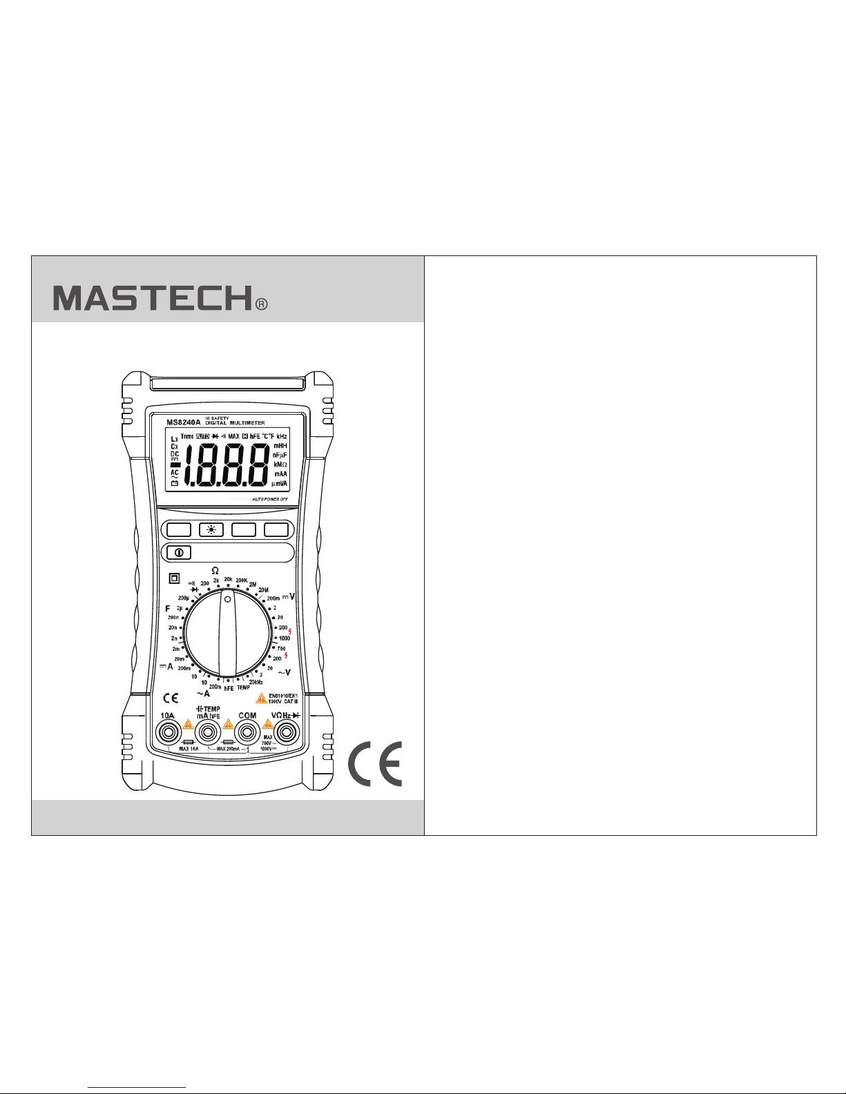
MS8240A
Digital Multimeters
Page 2
1. Preface
CONTENTS
5. Measurement Operation
5.1 DC Voltage and
AC Voltage Measurement
5.2 Resistance Measurement
5.3 Diode Test
5.4 Continuity Measurement
5.5 Capacitance Measurement
5.6 Transistor Measurement
5.7 Frequency Measurement
5.8 Current Measurement
5.9 Temperature Measurement
.....................................................1
........................10
...................10
2. Safety Information
3. Product Overview
...................................1
....................................3
3.1 Product Outline and its Description
3.2 Function Keys
........3
.......................................4
4. Technical Indicators
................................5
4.1 General Characteristics
4.2 Electrical Technical Indicators
.........................5
...............6
....................11
...........................................12
.....................13
..................14
......................15
.....................16
.........................16
..................18
6. Maintenance
...........................................19
6.1 Battery Replacement
6.2 Fuse Replacement
6.3 Others
...........................19
..............................19
................................................19
01
1. Preface
This dig ital mu ltime ter (he reinafter referred to a s
the “m eter” ) is a pock et-si zed multifunction ins trume nt
that uses 4 x1. 5V SIZE AA ba tteri es.
This ser ies of pr oduct s is desi gned with beautiful
appearanc e, firm s truct ure and excellent durability.
It use s elast ic ABS mat erial a nd double-injection
molding des ign, an d has goo d shock -resistant
performan ce.
The mete r meets G B/T 13978 -92 dig ital multimeter
general tec hnolo gy stan dards a nd GB4793.1-1995
(IEC -6101 0-1: 20 01) ele ctron ic measurement
instrumen t safet y requi rements, with class-I I
pollution a nd over -volt age sta ndard CAT III 600V.
Its fu ll func tion pr otect ion ensures the safe and
proper use of t he mete r.
As a gene ral ele ctric al meas uring a nd testing device,
this meter ca n be wide ly used i n the social electronic
fields such a s schoo ls, res earch institutes and fa ctori es.
2. Safety Information
The user shou ld obse rve to th e following safety tips i n
Warning
Plea se part icula rly not e that inappropriate use may
cause shock o r damag e to the me ter. The user
should comp ly with c ommon s afety procedures and
completel y follo w the saf ety measures stated in th is
operation m anual .
In order to mak e full us e of the me ter's functions
and ensure sa fe oper ation , pleas e carefully follow
the procedu res des cribe d in this s ection.
Page 3
FUNC
HOLD
MAX
FUSED FUSED
0302
orde r to avoi d perso nal inj ury and m eter malfuncti on
that m ay be cau sed by el ectri c shock.
• Do not measur e any vol tage ou tside the measurement
rang e speci fied by t his met er.
• Alth ough th ere is an i ntern al protection circuit in the
resi stanc e measu remen t position, do not apply an y
high v oltag e (abov e 100V) i n the resistance
meas ureme nt posi tion.
• Check the tes t wire fo r any dam age or bare metal.
• The me ter sho uld not b e used in d irect sunlight or high
temp eratu re.
• Please note t hat pos sible e lectric shock may be
caus ed if inp ut volt age exc eeds 36V AC or 48C DC.
• Befo re meas uring c urren t, please first switch off th e
equi pment t o be meas ured, a nd disconnect the
meas ured ci rcuit . Th en, con nect the test probe
secu rely, swit ch on the p ower, an d then start measuring.
• Pay at tenti on to cor rect ba ttery polarity when rep lacin g
batt eries .
• Be sur e to use a fu se with t he same s pecification and
mode l when re placi ng it.
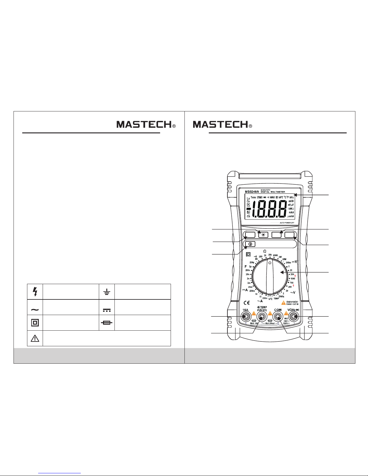
Electric symbols:
Dangerous v oltag e Grou nding
AC
(Alternating Current)
Double insu latio n
Warning,
please see the related instructions in the manual
DC (Direct Cu rrent )
Fuse
AC DC
3. Product Overview
3.1 Product Outline
FRONT PANEL
1
2
3
4
5
6
8
7
11
10
9
Page 4
04 05
Appearance description
1. Liquid cry stal di splay ( LCD)
2. Max imum ke y
3. Data hold ke y
4. Kno b
5. Inp uts of vo ltage , resis tance, frequency and di ode
6. Common end
7. Inp uts of cu rrent , capac itance and temperatur e
8. Inp ut of lar ge curr ent
9. Pow er swit ch key
10. Fu nctio n choic e
11. Backl ight co ntrol k ey
3.2 Function Keys
Function sw itch ke y: used f or temperature
measuring r ange sw itch (° C and °F), and
diode measu ring ra nge swi tch bet ween diode
mode and cont inuit y mode.
Hold key: Dur ing mea surin g, pres s this key.
The cu rrent d ispla yed rea dout of the meter is
locked on the d ispla y and it wi ll be unl ocked
afte r you pre ss the ke y again .
Maximum key : Durin g measu ring, p ress this
key to d ispla y the cur rentl y measured
maximum of th e meter. P ress ag ain to exit the
maximum dis play mo de.
Backlight f uncti on key: The b acklight will light
on if yo u press a nd hold t his key f or 2 seconds.
It wil l turn off au tomat icall y after 15 seconds.
Press again t o exit th e backl ight function.
Press to swit ch the me ter on or o ff .
FUNC
HOLD
MAX
4. Technical Indicators
4.1 General Characteristics
Manual meas uring r ange DM M, with 1 999 in count
under full ra nge.
Display: 3 1/ 2-bit L CD disp lay
Over load pr otect ion: Fu ll-function and
full -rang e protection.
Data holdin g funct ion
Maximum mea surem ent
Backlight
Low-volta ge disp lay
Auto matic p ower- off
Operating t emper ature a nd humi dity:
0~ 40° C (32~1 04°F);
relative hu midit y <80%R H
Stor age tem perat ure and h umidi ty:
-10~ 5 0°C (14 ~122°F);
relative hu midit y < 70%RH
Power suppl y: 1.5V b atter y (AA type)×4
Safe ty leve l: IEC6 1010- 1 and CAT III 600V
Dimension ( L×W×H ): 205× 102×5 8mm,
Weight : About 39 0g
Page 5

06 0 7
Input imped ance: 1 0MΩ; ma ximum input voltage:
1000V DC
Over load pr otect ion: 20 0mV measuring range:
250V DC or AC (RMS )
Input imped ance: 1 0MΩ; ma ximum input voltage:
750V DC
Over load pr otect ion: 25 0V DC or AC (R MS)
Freq uency r ange: 4 0 ~400H z
Response: Aver age res ponse ( sine wa ve RMS)
4.2.1 DC volt age
Measuring range
Resolutio n
Accu racy
200mV 0.1mV
2V
20V
200V
1000V
1mV
10mV
100mV
1V
±(0.7% reading + 3digits)
±(0.8% reading + 5digits)
4.2.2 AC vol tage
Measuring range
Resolutio n
Accu racy
2V
20V
200V
750V
1mV
10mV
100mV
1V
±(0.8% reading + 3digits)
±(1.0% reading + 5digits)
4.2 Electrical Technical Indicators
(Environm ent tem perat ure: 23±5°C,
relative hu midit y: <75% )
4.2.3 Diode
Measuring range
Resolutio n
Function
0.001V
Display forward voltage
drop of diode
Backward DC v oltag e: About 1 .5V
Forw ard DC cu rrent : About 1m A
Over load pr otect ion: 25 0V DC or AC (RMS)
4.2.4 Resis tance
Measuring range
Resolutio n
Accu racy
200Ω 0.1Ω
2kΩ
20kΩ
200kΩ
2MΩ
20MΩ
1Ω
10Ω
100Ω
1kΩ
10kΩ
±(1.0% reading + 3digits)
±(1.2% reading + 5digits)
Open circui t volta ge: Abou t 0.45V
Over load pr otect ion: 25 0V DC or AC (RMS)
4.2.5 Circu it cont inuit y
Measuring range
Function
The buzzer will sound when the
resistance is less than (50±20) Ω
Open circui t volta ge: Abou t 0.5V
Over load pr otect ion: 25 0V DC or AC (RMS)
Page 6

08 0 9
4.2.6 DC curr ent
Measuring range
Resolutio n
Accu racy
2mA
20mA
200mA
10A
1µA
10µA
100µA
10mA
±(1.0% reading + 5digits)
±(1.5% reading + 8digits)
Maximum cur rent: 2 00mA for m A jack and 10A for A jack
Over load pr otect ion: mA me asuring range:
F250mA/1K V fuse
10A measurin g range : F10A/ 1KV fuse
4.2.7 AC cur rent
Measuring range
Resolutio n
Accu racy
200mA
10A
10µA
1mA
±(1.5% reading + 5digits)
±(2.0% reading + 8digits)
Maximum cur rent: 2 00mA for m A jack and 10A for A jack
Over load pr otect ion: mA me asuring range:
F250mA/1K V fuse
10A measurin g range : F10A/ 1KV fuse
Freq uency r ange: 4 0 - 400HZ
Response: Aver age (si ne wave R MS)
4.2.8 Transi stor hF E
Measuring range
Function
Display approximation: 1 ~1000 times
Base curren t : About 1m A, Vce: Ab out 2.5V
Protectio n: 250m A/1KV f ast melting fuse
hFE
4.2.9 Tem perat ure
Measuring range
Resolutio n
Accu racy
-20°C~0°C
1°C
±(5.0% reading + 4digits)
0°C~400°C
400°C~1000°C
±(2.0% reading + 3digits)
±(3.0% reading + 3digits)
Over load pr otect ion: F2 50mA/1KV fast melting f use
250V DC or AC RMS
-0°F~32°F
1°F
±(5.0% reading + 4digits)
32°F~752°F
752°F~1832°F
±(2.0% reading + 3digits)
±(3.0% reading + 3digits)
4.2.10 Capa citan ce
Measuring r ange
Resoluti
Accu racy
2nF
0.001nF
±(4.0% reading + 15digits)
20nF
200nF
2µF
200µF
0.01nF
0.1nF
1nF
100nF
Over load pr otect ion: F2 50mA/1KV fast melting f use
36V DC o r AC RMS
4.2.11 Frequ ency
Over load pr otect ion: 25 0V DC or AC (R MS)
Measuring r ange: 1 V~10V R MS
Measuring range
Resolutio n
Accu racy
20kHZ 100HZ
±(1.5% reading + 15digits)
Page 7

10 11
5.1 DC Volta ge and AC Volt age M eas urement
5. Measurement Operation
Warning
1. Do not measu re any RM S volta ge high er than
1000 V DC or 750 V AC. This pre vents e lectrical
shoc k and/o r meter d amage .
2. Do not measu re any RM S volta ge high er than
1000 V DC or 750 V AC betwe en the co mmon en d
and gr ound. Thi s preve nts ele ctrical shock and/or
mete r damag e.
The volt age mea surin g range o f this meter:
DC vol tage: 2 00.0m V, 2.00 0V, 20. 00V, 20 0.0V and
1000 V;
AC volt age: 2. 000V, 20.00V, 200.0 V and 750 .0V
Method of mea surin g volta ge:
1. Rotate swi tch to th e appro priate position.
2. Connect bl ack and r ed test p robe to COM input socket
and V in put soc ket, re spect ively.
3. Mea sure th e volta ge of cir cuit to be tested with othe r
two en ds of tes t probe s. (Con nected with the circuit t o
be tes ted in pa ralle l).
4. Read the mea sured v oltag e value from LCD display.
When m easur ing DC vo ltage , the display will
simu ltane ously s how the v oltage polarity which is
conn ected w ith red t est pro be.
Note :
In the D C 200Mv a nd AC 2V mea surin g ranges,
the me ter wil l have va rious r eadou ts due to interference
from t he extr ernal s ource s, but this does not affect the
normal use an d measu remen t accur acy of the meter.
5.2 Resistance Measurement
Warning
To avoid damagi ng mete r or devi ce to be me asured,
before meas uring r esist ance, turn off all circuits t o
be tes ted and d ischa rge all h igh vol tage capacitors.
The re sista nce mea surin g range o f this meter:
200.0Ω, 2.0 00KΩ, 2 0.00K Ω, 200.0KΩ,
2000MΩ, 20. 00MΩ
Method of mea surin g resis tance:
1. Rotate swi tch to th e appro priate position.
2. Connect bl ack and r ed test p robe to COM input
sock et and V in put soc ket, re spectively.
3. Mea sure th e resis tance v alue of circuit to be teste d
with o ther tw o ends of t est pro bes.
4. Read the mea sured v alue fr om LCD di splay.
Note :
1. A circuit's me asure d resis tance value is usually
differ ent fro m the rat ed valu e of resistance. Thi s is
beca use the c onnec tion be tween the other elements
on the c ircui t and tes ted res istance can be equal to
the pa ralle l conne ction o f two or more resistances .
2. To accura tely me asure l ow resi stance, make a short
circ uit bet ween th e two tes t probes and read the
resi stanc e value o f the sho rt circuit. Subtract th is
valu e from th e measu red val ue of the resistance in
the ci rcuit t ested .
3. Whe n measu ring in t he high -resi stance range, the
read ing wil l be stab lize af ter several seconds.
4. In th e open ci rcuit s tate, t he meter will display “OL ”,
indi catin g that th e measu red value exceeds the
meas uring r ange.
Page 8

12 13
5.3 Diode Measurement
Warning
To avoid damagi ng the me ter or de vice to b e
measured, b efore m easur ing dio des, turn off all
circuits to b e teste d disch arge all high voltage
capacitor s.
Method of mea surin g diode s:
1. Rotate the s witch t o position.
2. Connect bl ack and r ed test p robe to COM input socket
and V in put soc ket, re spect ively.
3. Connect bl ack and r ed test p robe to negative pole and
posi tive po le of the d iode to b e tested, respectivel y.
4. The met er will d ispla y the for ward bias voltage value
of dio de test ed. If th e test pr obe polarity is reverse d,
the me ter wil l displ ay “OL” .
Note :
When measur ing a dio de on a cir cuit, the meter will
display the f orwar d volta ge drop for forward measuring;
when connec ted in re verse , readi ngs will depend on the
values of oth er elem ents co nnected in parallel on two
ends on the dio de.
5.4 Continuity Measurement of Buzzer
Warning
To avoid damagi ng mete r or devi ce to be me asured,
before cont inuit y tests , turn off all circuits to be
test ed and di schar ge all hi gh volt age capacitors.
Method of con tinui ty test :
1. Rotate the s witch t o position, and press the
FUNC k ey once .
2. Connect bl ack and r ed test p robe to COM input socket
and V in put soc ket, re spect ively.
3. Connect th e test pr obes to t he two ends of the tested
appl iance a nd circ uit res pectively.
4. The met er will d ispla y the app roximate resistance
valu e betwe en two te sted po ints. If the resistance
valu e betwe en the tw o teste d points is less than
(50± 20)Ω, t he buzz er will s ound.
Page 9

14 15
5.5 Capacitance Measurement
Warning
To avoid damagi ng mete r or devi ce to be me asured,
before cont inuit y tests , turn off all circuits to be
test ed and di schar ge all ca pacit ors.
The ca pacit ance me asuri ng rang e of this meter:
2.000nF, 20.0 0nF, 200. 0nF, 2.00 0uF and 2 00.0uF.
Method of mea surin g capac itance:
1. Rotate swi tch to th e appro priate position.
2. Connect bl ack and r ed test p robe to COM input socket
and V in put soc ket, re spect ively. (You can also use
the de dicat ed mult ifunc tion test holder to measu re
capa citan ce).
3. Mea sure th e two lea ds of the c apacitor to be tested
with o ther tw o ends of t est pro bes and read the
meas ured va lue fro m LCD dis play.
Note :
When measur ing bul k capac itors w ith this meter,
readings wi ll be sta blize e after a f ew seconds.
When measur ing the s mall ca pacit or with less than 20nF,
the distrib uted ca pacit ance (d isplayed base number)
of the m eter an d wire sh ould be s ubtracted.
5.6 Transistor Measurement
Warning
Do not apply an y RMS vol tage hi gher th an 250V DC
or AC between co mmon en d and hFE e nd.
This preven ts elec trica l shock and/or meter dama ge.
Method of mea surin g trans istor:
1. Rotate the s witch t o hFE pos ition.
2. Plu g multi -func tion so cket with correct polar ity
(the “ +” end of m ulti- funct ion socket is connected w ith
hFE en d, “COM ” end is co nnect ed with common end).
3. Determin e that th e trans istor is NPN or PNP type,
then i nsert t hree pi ns of tra nsistor, e.b.c, to the
corr espon ding ho les of de dicated multi-functional
sock et.
4. Read hFE app roxim ation o f transistor to be measur ed
from L CD disp lay.
Page 10

16 17
5.7 Frequency Measurement
Warning
Do not measur e the fre quenc y of RMS voltage
higher than 2 50V DC or AC . Th is prev ents electrical
shock and/o r meter d amage .
Method of mea surin g frequ ency:
1. Rotate swi tch to 20 KHZ pos ition.
2. Connect bl ack and r ed test p robe to COM input socket
and HZ i nput so cket, r espec tively.
3. Mea sure th e frequ ency va lue of circuit to be tested
with o ther tw o ends of t est pro bes.
4. Read the mea sured f reque ncy val ue from LCD display.
Note :
Do not input th e volta ge over 1 0V RMS, as accuracy of
readings ca nnot be g uaran teed.
5.8 Current Measurement
Warning
To avoid damage t o meter o r devic e, before
measuring c urren t, plea se chec k the meter's fuse .
When measur ing, us e corre ct input socket, functi on
selection a nd meas uring r ange.
When the circ uit vol tage is o ver 250V, do not attempt
to mea sure cu rrent o n the cir cuit.
When the test p robe is i nsert ed to the current input
socket, don 't conn ect the o ther end of the test probe
with a ny circ uit in pa ralle l.
DC measurin g range o f meter :
2.000mA, 20 .00mA , 200.0 mA and 10.00A;
AC measurin g range : 200.0 0mA and 10 A.
Method of mea surin g curre nt:
1. Turn off t he powe r suppl y and dis charge all high
volt age cap acito rs on the c ircuit to be tested.
2. Rotate swi tch to th e appro priate position.
3. Connect th e black t est pro be to the COM input socket.
If the c urren t to be tes ted is lo wer than 200mA, connect
the re d test pr obe to th e mA input s ocket. If the
meas ured cu rrent i s betwe en the range of 200mA~10A ,
the re d test pr obe sho uld be co nnected to 10A input
sock et.
4. Turn off t he circ uit to be t ested . Connect the black test
prob e to the lo w volta ge end of d isconnected circuit t o
be tes ted and t he red te st prob e is connected to the
othe r end (hi gh volt age) of d isconnected circuit .
5. Connect th e power s upply t o the circuit, then read th e
LCD di splay. If th e displ ay show s only “OL”, it means
that t he inpu t is out of t he sele cted input range.
Plea se rota te the sw itch to a h igher measuring range .
6. Turn off t he powe r to the ci rcuit t ested. Discharge all
the ca pacit ors, re move th e test probes from the mete r
and re store t he circ uit to th e original state.
Note :
1. Whe n measu ring cu rrent , the meter should be
conn ected i n serie s, inst ead of in parallel, to avoi d the
mete r damag e and ris king pe rsonal safety.
2. Len gthy me asure ments o f large currents (>10A) w ill
affect t he disp lay acc uracy o f the meter. Standard test
time c annot b e over 10 s econd s in any 3 minute period.
3. During DC me asure ment, i f the test probes are
conn ected i n rever sal ord er to the circuit, the disp lay
will b ecome n egati ve, but t he measurement accura cy
of the m eter wi ll not be a ff ected .
Page 11

18 19
6.1 Battery Replacement
6. Maintenance
5.9 Tem perature Measurement
Warning
Do not input an y volta ge high er than 1 2V DC or AC
RMS within th e tempe ratur e measuring range, to
avoid damag e to the me ter.
Method of mea surin g tempe rature:
The MS 3203 mu ltifu nctio n socket with K-type
temp eratu re prob e is requ ired fo r measuring temperatu re.
1. Rotate the k nob to th e TE MP positi on. The LCD will
disp lay “OL ” and tem perat ure unit °C.
2. Whe n inser ting th e multi function socket, inse rt “COM ”
and “V ” leads o f the soc ket in th e comm end and
curr ent MA jac ket res pecti vely.
3. Then in sert th e tempe ratur e probe into the side
temp eratu re jack et of the m ultifunction socket .
Note t he pola rity of t he atta chment. The LCD will
disp lay the t emper ature o f the current environme nt.
4. The oth er end of t he temp eratu re probe
(the t emper ature s ensor ) is put into the object to be
test ed. The LCD w ill dis play th e temperature at the
loca tion of t he curr ent sen sor.
5. Pre ss the “F UNC” ke y to conv ert the measured value
to °F, or se t the tem perat ure uni t to °F first before
meas uring .
When the symb ol show s on the di splay during
use of the mete r, you mus t repla ce the batteries, to
avoid affecti ng the no rmal us e of the meter.
Method of rep lacin g batte ries:
1. Disconne ct the te st wire . Switch off the power.
2. Ope n the bat tery co ver on th e rear of the case with
the sc rewdr iver, an d remov e the batteries.
3. Ins tall ba tteri es with s ame specification,
and se cure th e cover.
6.2 Fuse Replacement
Steps for rep lacin g fuse:
1. Fir st remo ve the te st wire , and switch off the meter.
2. Ope n the bat tery co ver on th e rear cover with the
scre wdriv er, and re move th e damaged fuse.
3. Ins tall a fu se with s ame spe cification, put the bat tery
cove r in plac e again , and tig hten the screws.
6.3 Cleaning
Please wipe t he surf ace of th e meter with the soft cloth
and mild dete rgent , if nece ssary. Do not use organic
solvents as t hey wil l corro sion the meter's case.
Page 12

HYS006664
 Loading...