

Page 1

MASTECH®
MS8239B
DIGITAL MULTIMETER
USER’S MANUAL
Page 2

TABLE OF CONTENT
LIMITED WARRANTY AND LIMITATION OF
LIABILITY ................... 錯誤! 尚未定義書籤。
Out of the Box ................................................ 3
Accessories ..................................................... 4
Certification.................................................... 7
INTRODUCTION ........................................... 7
Overview ........................................................ 7
Figures and Components................................ 7
Buttons and Components............................ 8
Display Description ................................... 10
USING THE METER ..................................... 11
Preparation ............................................... 11
DC/AC Voltage Measurement ................... 12
AC/DC Current Measurement ................... 13
Resistance Measurement .......................... 15
Diode ......................................................... 16
Continuity .................................................. 16
1.5V 9V and 12V Battery Test ................... 17
1
Page 3

SPECIFICATIONS ........................................ 18
General Specification ................................... 18
Technical Specifications ............................... 19
MAINTENANCE AND REPAIR ..................... 23
Repair ........................................................ 23
Test Leads Replacement ............................... 24
Replacing Batteries ..................................... 25
Replacing Fuse ............................................. 25
2
Page 4

LIMITED WARRANTY AND
LIMITATION OF LIABILITY
This MS8239B product from MASTECH will be free from
defects in material and workmanship for one year from
the date of purchase. This warranty does not cover
fuses, disposable batteries, or damage from drops,
neglect, misuse, alteration, contamination, or abnormal
conditions of operation or handling. Resellers are not
authorized to extend any other warranty on MASTECH’s
behalf. To obtain service during the warranty period,
contact your nearest MASTECH authorized service
center to obtain return authorization information and
then send the product to that Service Center with a
description of the problem.
Out of the Box
Check the Meter and accessories thoroughly before using
the Meter. Contact your local distributor if the Meter or
any components are damaged or malfunction.
3
Page 5
Accessories
WARNING
TO REDUCE THE RISK OF FIRE, ELECTRICAL SHOCK,
PRODUCT DAMAGE OR PERSONAL INJURY, PLEASE
FOLLOW THE SAFETY INSTRUCTIONS DESCRIBED IN THE
USER’S MANUAL. READ THE USER’S MANUAL BEFORE
USING THE METER.
WARNING
TO ENSURE SAFE OPERATION AND LIFE OF THE METER,
DO NOT PLACE THE METER IN ANY ENVIRONMENT WITH
HIGH PRESSURE, HIGH TEMPERATURE, DUST, EXPLOSIVE
GAS OR VAPOR.
Test Leads 1set
1.5V AAA Battery 2pcs
User’s Manual
Safety Information
4
Page 6

Avoid shaking, dropping or any kind of
impacts when using or transporting the Meter.
To avoid electric shock or personal injury,
repairs or servicing not covered in this manual
should be performed only by qualified
personnel.
Avoid direct exposure to sunlight to ensure
extended life of the Meter.
Do not place Meter in a strong magnetic field;
this may cause false readings.
Use only the batteries indicated in the
Technical Spec.
Avoid exposing batteries to humidity. Replace
batteries as soon as the low battery indicator
appears.
Please keep the original packing for future
shipping purposes (ex. Calibration)
After opening the box, check for any damage
during delivery.
5
Page 7
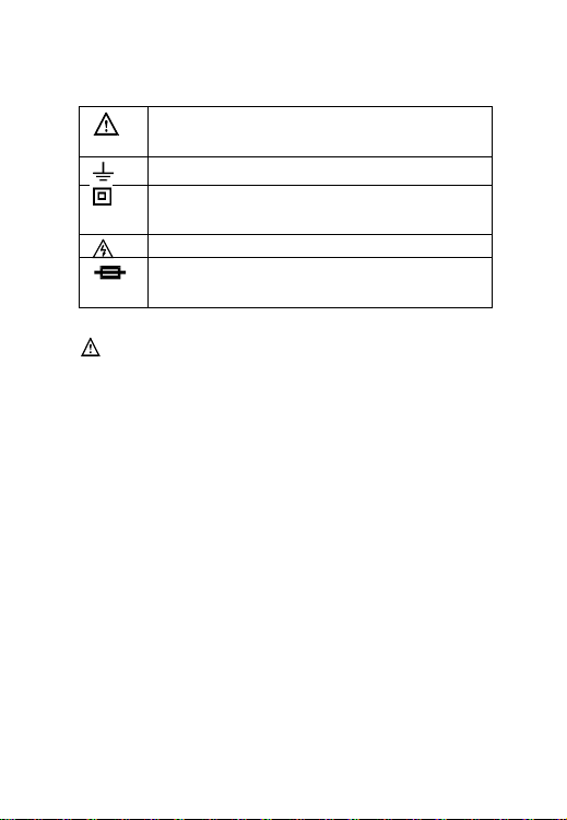
Safety Symbols on the Meter
Important safety information, please refers
to the user manual
Earth ground
Indicates compliance with requirements for
double insulation
Possible of high voltage
Fuse must be replaced with ratings specified
in the manual.
Important Safety Information
Never use the Meter to measure voltages that
might exceed 600V DC/AC above earth
ground.
Always be careful when working with voltages
above 60V DC or 30V AC RMS. Keep fingers
behind the probe barriers while measuring.
Never connect the Meter leads across a
voltage source while the rotary switch is in
the resistance, diode or continuity mode.
Doing so can damage the Meter.
Do not perform resistance, diode and
continuity measurements on powered circuits.
6
Page 8

Inspect test leads and probes for cracks,
breaks or crazes on the insulation before
using the Meter.
Repair or maintenance should be
implemented by trained personnel.
Certification
CAT III: This meter has meet IEC61010-1
standard with an overvoltage category (600V
CAT III) and pollution degree 2.
The Meter is compiled to EMC
requirements.
Introduction
Overview
The MS8239B is a compact and portable multifunction
digital multimeter featuring an easy-to-read LCD screen.
Basic functions include: AC/DC voltage, AC/DC current,
resistance, diode, continuity measurements and battery
test. This MS8239B is ideal for any entry level use.
7
Page 9

Figures and Components
Buttons and Components
1. LCD (liquid-crystal display)
2. HOLD Button
3. Rotary Switch
4. 10A Input Jack
5. COM Input Jack
6. mA/V/Ω/ Input Jack
8
Page 10

6
5
4
3
2
1
Front Panel
9
Page 11

Display Description
1.
2. Hold
3. Reading Display
4. Polarity
10
Low Battery Indicator
Page 12

Using the Meter
Preparation
Switch on the power by turning the rotary
switch. If the battery voltage is lower than
2.8V, the“ ”symbol will appear and the
batteries should be replaced.
The “ ” symbol next to the input lead
shows that the input voltage or current should
not exceed the specified value in order to
protect the internal circuit from damage.
Turn the rotary switch to the required
function and range to be measured.
Choose the highest range when the value to
be measured is unknown.
When making connection, connect the
common test lead first and then the powered
test lead.
Removed the charged test lead first when
disconnecting.
11
Page 13

Readings Hold
WARNING
USE CAUTION WHEN MEASUREING HIGH VOLTAGE
CIRCUITS TO AVOID ELECTRICAL SHOCK AND
INJURY. DO NOT TEST VOLTAGES HIGHER THAN
DC/AC 600V.
Press “HOLD” button to hold the readings of
current measurement.
Press “HOLD” button again to release the hold.
DC/AC Voltage Measurement
Plug the black test lead into “COM” jack and
the red test lead into “V” jack.
Set the rotary switch to “V~” (AC), or “V ”
(DC) position in the corresponding range.
Connect the test leads to the voltage source
or load for measurement.
Read the result on the LCD. The polarity
symbol denotes the polarity of the end
connected by the red test lead.
12
Page 14

NOTE:
WARNING
USE CAUTION WHEN MEASUREING HIGH VOLTAGE
CIRCUITS. TO AVOID ELECTRICAL SHOCK AND
INJURY. DO NOT TEST VOLTAGES HIGHER THAN
DC/AC 600V.
o At a small voltage range, unsteady readings
will appear before the test leads makes
contact with the circuit. This is normal since
the Meter is highly sensitive. When the test
leads are connected to the circuit, the true
reading will be shown.
o Under any range mode, when ‘1.’ is shown on
the LCD it means the measurement has
exceeded the allowable range. A higher range
should be selected.
o When the value to be measured is unknown,
select the highest range first and lower the
range accordingly.
AC/DC Current Measurement
13
Page 15

Plug the black test lead into the “COM” jack.
Set the rotary switch to “A~” (AC) or “A ”
(DC) position in the corresponding range. For
example, when the current to be measured is
under 200mA, plug the red test lead into “mA”
jack and turn the switch to “200mA”; when
the current to be measured is over 200mA but
under 10A, plug the red test lead into the
“10A” jack and turn the switch to “10A”.
Connect the test leads to the circuit.
Read the result on the display.
The polarity symbol denotes the polarity of
the red test lead.
NOTE:
o Under any range mode, when‘1.’is shown on
the LCD it means the measurement has
exceeded the allowable range; a higher range
should be selected.
o When the value to be measured is unknown,
select the highest range first and then lower
the range accordingly.
o “ ” indicates the maximum current of the
mA jack is 200mA and the maximum
current of the 10A jack is10A.At the 10A
14
Page 16

jack, current exceeding the limit will blow the
WARNING
TO AVOID ELECTRICAL SHOCK AND INJURY
POWER OFF THE CIRCUIT AND DISCHARGE THE
CAPACITANCE BEFORE MEASURING RESISTANCE.
fuse.
Resistance Measurement
Plug the black test lead into the “COM” jack
and the red test lead into the “Ω” jack.
Set the rotary switch to the “Ω” position with
corresponding range.
Connect the test leads to the ends of the
resistor or circuit.
Read the numbers on the LCD.
NOTE:
Under any range mode, when only ‘1.’ is shown on the
LCD, it means the measurement has exceeded the range
and a higher range should be selected. When the input is
open, ‘1.’is displayed on the LCD to indicate overload.
For measuring resistance above 1MΩ, it may take a few
seconds to get a steady reading. This is normal for high
resistance measurements.
15
Page 17

WARNING
TO AVOID ELECTRICAL SHOCK AND INJURY
POWER OFF THE CIRCUIT AND DISCHARGE THE
CAPACITANCE BEFORE MEASURING CONTINUITY
Diode
Plug the black test lead into the COM jack and
the red test lead into the jack.
Set the rotary switch to the range
position and select a proper range.
Connect the red test lead to the anode and
the black test lead to the cathode of the diode
for testing.
Read the result on the LCD.
NOTE:
o The Meter will show approximate forward
voltage drop of the diode.
o When the test leads are reversed or opened,
‘1.’will appear on the LCD.
Continuity
Plug the black test lead into the “COM” jack
and the red test lead into “mA/V/Ω/ ”jack.
16
Page 18

Set the rotary switch to the “ ” position.
Connect the test leads to two ends of the
circuit. If resistance of the circuit is less than
50Ωthe built-in buzzer will sound.
1.5V 9V and 12V Battery Test
To check if the battery is in good or bad condition,
switch the rotary switch to “BATT” and choose the
voltage according to the battery type.
Connect the red lead (+) to the (+) side of battery
and black lead (-) to the (-) side.
Read off the result from the display.
17
Page 19

Specifications
General Specification
Maximum voltage between terminals and
earth ground: 600V DC/AC
Operating altitude: max. 2000 meters (7000
ft.)
Display: 3.5’’ LCD
Maximum value of display: 1999
Polarity indication: automatic; ‘-‘for negative
polarity.
Overload indication: ‘1.’
Sampling time: approx. 3 times/ second
Function and Unit display
Fuse protection 1: F200mA/250V
Fuse protection 2: FF10A/600V
Power Supply : 1.5V×2 AAA batteries
Battery low indication: “
Operating Temperature: 0°C to 40°C (32°F to
104°F )
Storage Temperature: -10°C to 60°C (10°F to
140°F )
Dimension: 147×76.2×41mm (5.8 x 3 x 1.6 in.)
18
” on LCD
Page 20

Weight: approximate 230g (7.6oz) including
Range
Resolution
Accuracy
200mV
0.1mV
± (0.5% of reading + 3
digits)
2V
1mV
20V
10mV
200V
100mV
600V
1V
± (0.8% of reading + 3
digits)
Technical Specifications
DC Voltage
Input Impedance: 1MΩ
Maximum input voltage: 600V DC or AC RMS.
NOTE:
o At small voltages range, unsteady readings
19
batteries
will appear before the test leads make contact
with the circuit. This is normal since the meter
is highly sensitive. When the test leads
connect to the circuit, the true reading will be
shown.
Page 21

Range
Resolution
Accuracy
200V
0.1V
± (1.2% of reading + 10
digits)
600V
1V
Range
Resolution
Accuracy
200mA
0.1mA
±(1.2% of reading +5 digits)
AC Voltage
Input Impedance: 1MΩ
Maximum input voltage: 600V DC or AC RMS.
Frequency response: 40Hz~400Hz, sine wave RMS
(Average response)
NOTE:
o At small voltage ranges, unsteady readings
will appear before the test leads make contact
with the circuit. This is normal since the meter
is highly sensitive. When the test leads
connect to the circuit, the true reading will be
shown.
AC Current
20
Page 22

10A
10mA
±(2.5% of reading +10
digits)
Range
Resolution
Accuracy
200mA
100μA
±(1.0% of reading + 5 digits)
10A
10mA
±(2.0% of reading + 10 digits)
Overload protection:
o mA: Fuse (F200mA/250V)
o 10A: Fuse (FF10A/600V) protection.
Maximum input current:
o mA: 200mA DC or AC RMS
o 10A: 10A DC or AC RMS
Frequency response: 40Hz~400Hz, sine wave RMS
(Average response)
NOTE:
When measured current is greater than 2A, continuous
measurement time cannot be more than2 minutes.
Disconnect the current and wait 10 minutes before
making another measurement.
DC Current
Overload protection:
21
Page 23

o mA: Fuse (F200mA/250V)
Range
Resolution
Accuracy
200Ω
0.1Ω
±(0.8% of reading + 5 digits)
2kΩ
1Ω
20kΩ
10Ω
200kΩ
100Ω
2MΩ
1kΩ
Max. V
Resolution
Function
o 10A: Fuse (FF10A/600V)
Maximum input current:
o mA: 200mA DC or AC RMS
o 10A: 10A DC or AC RMS
NOTE:
When measured current is greater than 2A, continuous
measurement time cannot be more than2 minutes.
Disconnect the current and wait 10 minutes before
making another measurement.
Resistance
Open circuit voltage: ~0.25V
Overload protection: 250V DC or RMS AC
Diode Test
22
Page 24

2V
1mV
Displaying approximate
forward voltage of
diode
Overload Protection: 250V DC or RMS AC
Function
Built-in buzzer will sound if resistance is lower
than 60Ω.
Measuring
Range
Resolution
Built-in Load
Resistance
12V
0.01V
300Ω
9V
0.01V
1.8kΩ
1.5V
0.001V
36Ω
Continuity Test
Overload Protection: 250V DC or RMS AC
Battery Test
Maintenance and Repair
Repair
Please follow these steps closely if the Meter is not
functioning properly:
23
Page 25

WARNING
REPLACE THE TEST LEADS WITH IDENTICAL OR
COMPATIBLE LEADS. LEAD SPEC:1000V 10A.
Check batteries; replace with new batteries if
low battery indicator “ ” appears.
Follow User’s Manual to confirm all
procedures.
Before sending Meter back for repair, include
a description of the problems encountered.
Remove batteries and pack Meter well to
avoid damage in delivery, Dawson does not
cover damage due to delivery.
Repair or service not covered in this manual
should be performed only by the authorized
service center or qualified personnel.
Test Leads Replacement
Replace new leads if the current leads are worn.
24
Page 26

Replacing Batteries
Follow these steps to replace batteries:
Turn off the Meter.
Loosen the battery compartment door screw, and
remove the door from the case bottom.
Remove the batteries and replace the batteries
with new batteries.
Reattach the battery compartment door to the case
bottom and tighten the screw.
Replacing Fuse
Fuses rarely need replacement. Almost all blows are the
result of operation error.
Loosen the battery compartment door screws
like in the Replace Batteries.
Remove the red rubber cover.
Remove the screws located in the back.
Replace the blown fuse with one at the
specified rating.
Replace and tighten the screws located in the
back.
Put back on the red rubber cover.
Put the battery cover back and tighten the
screws.
25
Page 27

Do not recycle
26
 Loading...