

Page 1
MS8239A
User's Manual
Digital Multimeter
HOLD
10A
COM
MAX
10A/ 500V
MAX
200mA/ 250V
600V MAX
600V CAT III
IEC61010-1
BAT T.
A
V
V
200
600
20m
200m
10A
200
2k
20k
200k
2M
2
20
200
600
200m
9V
1.5V
12V
MS8239A
Auto Power Off
DIGITAL MU LTIMET ER
Page 2

CONTENTS
Safety Indicators..............................1
CONTENTS
Meter Appearance..............................5
Safe Working Habits..........................2
Overview..........................................1
Electric Symbols...............................4
Meter Instructions.............................5
Display..............................................5
Measuring Operation.........................7
Data Hold
DC/AC Voltage Mea surement........ .....7
..........................................7
DC Current Mea surement
Resistance M easurement
...................8
...................9
Continuity M easurement...................10
Diode Test
........................................10
Battery Test
......................................11
General Specifications.......................11
Accuracy Indicators...........................12
DC Voltage..........................................13
AC Voltage..........................................13
Resistance Measurement.....................14
Diode..................................................14
Continuity Measurement.......................14
DC Current..........................................15
Battery Test.........................................15
Maintenance.....................................15
General Maintenance...........................16
Replace Batt ery...................................16
Replace Fuse.......................................17
Page 3

01
02
Overview
Safe Working Habits
To avoid el ectric shock or personal inj ury, please
read “saf ety information” and “w arning and
rela ted n otes” carefully befor e using the meter.
The MS 823 9A is a small hand-held , saf e and reliable
3.5” d igi tal multimeter with sta ble p erformance and
novel str ucture. It can be used to mea sur e DC
voltage , DC current, resistanc e, di ode forward
voltage d rop, circuit continui ty an d to test batteries.
It is an i dea l maintenance tool easi ly ca rried by a
large num ber of users.
Warning
To avoid possible electric s hock or personal injury as
well as dam age to the meter or measure d obj ects,
please us e the meter according to th e fol lowing
procedu res:
Safety Instructions
The MS 823 9A digital multimet er ha s been designed
acco rdi ng to International Ele ctr o Safety Standard
IEC- 101 0 (61010-1@IEC: 2001) conc erning safety
require ments for electronic me asu ring instruments
and hand- held digital multimeters . It meets the
require ments for CAT.III 600V of IEC1010 and g rad e
2 for po llu tion.
• Users sho uld use the meter strictl y acc ording to
the pr ovi sions of this manual. Oth erw ise, the
warr ant y for the meter may become in val id.
• The wa rni ngs in the user manual are used to r emind
user s of po ssible dangers or dange rou s actions.
• The no tes i n the user manual are to remi nd us ers
of con dit ions or actions that may ca use d amage
to the m eas ured object.
• Check the c ase before using the mete r. Don't use the
mete r wit h damaged case. Check to se e if th e case is
crac ked o r lacks plastic parts. Pl eas e pay special
atte nti on to the joint insulatin g lay er.
• Check to se e if the test wire has insula tio n damage or
bare m eta l. Check test wire contin uit y. If the wire is
dama ged , please replace it with a ne w one b efore
usin g the m eter.
• Measure k nown voltage with the met er to v erify that
the me ter i s working properly. If the met er is working
abno rma lly, stop using it immediate ly. A protec tiv e
devi ce ma y be damaged. If there is any d oub t, please
have t he me ter inspected by a qualif ied t echnician.
• Do not test v oltage exceeding rate d vol tage marked
on the m ete r.
• When t est ing voltage exceeding 3 0v AC voltage RMS,
42v AC pe ak or 60v DC, be particular ly careful to
avoi d ele ctric shock.
• When m eas uring, use correct jack , and s elect the
prop er fu nction and measuring ra nge .
• Do not use th e meter in explosive gas, v apo r or dusty
envi ron ments.
• When u sin g the probe, fingers shou ld be b ehind the
prob e pro tection device.
Page 4
03
04
• When c onn ecting circuits, conn ect t he common test
line firs t, then connect the charg ed te st line. When
disc onn ecting circuits, disc onn ect the charged test
line firs t, then disconnect the co mmo n test line.
Befo re me asuring resistance, c ont inuity, and diodes,
firs t tur n off pow er and discharge all high volt age
capa cit ors.
• If the m ete r is not used in accordance w ith t he
inst ruc tions, the meter's safe ty protective function
may be com e invalid.
• For al l DC me asurements, to avoid th e ris k of
elec tri c shock, please use AC fu nction to verify the
exis ten ce of any AC voltage. Then, sele ct DC
volt age m easuring range equal to o r gre ater than
the AC me asuring range.
• Befo re me asuring current, plea se ch eck the meter
fuse , shu t off pow er to the circuit to be teste d, then
conn ect t he meter and energize the c irc uit.
• When o pen ing the case (or part of the ca se) , turn
the me ter o ff.
• When t he ba ttery low voltage indic ato r “ ”
beco mes l it, replace the battery a t onc e. A low
batt ery w ill cause meter reading e rro rs and may
resu lt in e lectric shock or person al in jury.
• Befo re op ening the case or the batte ry co ver,
remo ve th e test wire from the meter.
When m ain taining the meter, us e replacement parts
spec ifi ed by the factory.
Electric Symbo ls
Impor tant safe ty inf ormatio n
AC (Alt ernatin g Curr ent)
DC (Dir ect Curre nt)
AC or DC
Groun d wire
Fuse
Accor d with the re late d EU laws and r egulati ons
Page 5

05
06
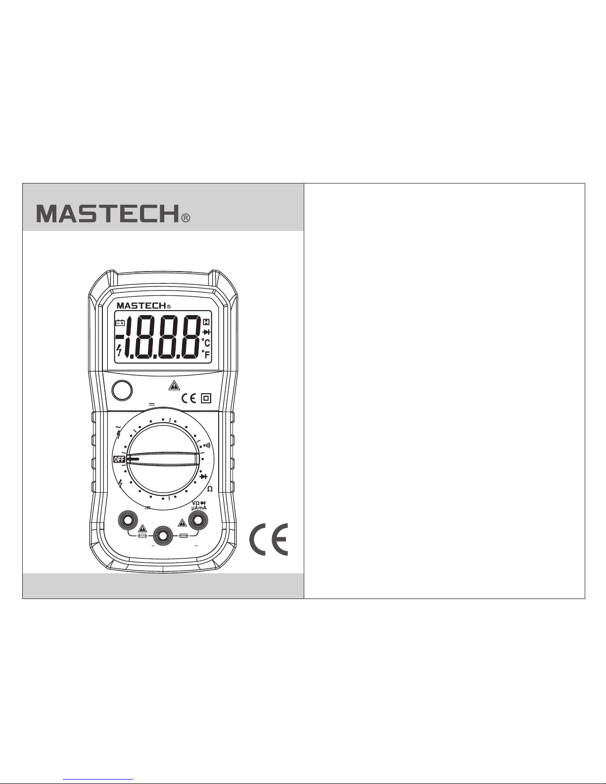
(1) LCD d isplay
(2) Dat a hold key
(3) Fun ction sel ecti on rotary s witch
(4) Pos itive inp ut jac k of 10A (conn ected wit h the
red tes t probe).
(5) All th e common in put ja cks for mea suring
(conn ected wit h the bl ack test pr obe).
(6) Pos itive inp ut jac k of voltag e, resist ance , mA
curre nt, diode , cont inuity an d battery t est
(conn ected wit h the re d test prob e).
Meter Instructions
Meter Appearance
Display
(1) Bat tery low vo ltag e indicat or
(2) Dat a hold indi cato r
(3) Num erical va lue di splay
(4) Num erical va lue po larity in dicator ( nega tive sign )
HOLD
10A
COM
MAX
10A/ 500V
MAX
200mA/2 50V
600V MAX
600V CAT III
IEC61010-1
BATT.
A
V
V
200
600
20m
200m
10A
200
2k
20k
200k
2M
2
20
200
600
200m
9V
1.5V
12V
MS8239A
Auto Power Off
DIGITAL MULTIM ETER
1
2
3
4
5
6
Page 6

07
08
Measuring Operation
DC Current Measu rement:
Data Hold
The dat a hold func tion c an keep the c urrent re adin gs
on the di splay. To enter an d exit reading ma intenan ce
mode:
Press t he “HOLD” key, th e reading w ill be s tored
and “H” s ymbol will disp lay on the LC D display.
Press t he “HOLD” k ey aga in to retur n the meter
to the no rmal meas urem ent state .
1
2
AC/DC Voltage Meas urement:
Rotat e the funct ion se lection s witch to ap prop riate
AC or DC vol tage meas urem ent posit ion.
Conne ct the blac k and re d test prob es to the COM
input j ack and VΩm A input j ack, resp ectivel y..
Measu re the volt age of c ircuit to b e tested wi th
other e nds of test p robe s (connec ted with th e
circu it to be test ed in pa rallel) .
Read th e measure d valu e from the LC D display.
When me asuring t he DC vo ltage, th e display w ill
simul taneous ly sho w the volta ge polari ty whi ch is
conne cted with t he red t est probe .
1
2
3
4
Don' t mea sure any RMS voltage high er than 600V
DC or AC, to prevent inj ury o r damage to meter
and eq uip ment.
Warning
Turn off the po wer to the ci rcuit to be t ested.
Disch arge all th e high v oltage ca pacitor s on the
circu it to be test ed.
Rotat e the funct ion se lection s witch to th e
appro priate DC c urre nt positi on.
Depen ding on the s ize of t he curren t to be
measu red, conn ect th e red test pr obe to 10A or mA
input j ack; conn ect th e black tes t probe to CO M
input j ack.
Turn off the ci rcuit to be t ested. Co nnect the b lack
test pr obe to one en d of the d isconne cted circ uit
(low vo ltage rel ativ ely), and t he red test p robe i s
conne cted to the o ther e nd of disco nnected c ircu it
(high v oltage re lati vely). (R eversin g test p robes
would m ake readi ng bec ome negat ive, but th e
meter w on't be dam aged .)
Conne ct the powe r supp ly to the cir cuit, the n read
the dis play read ing. I f the displ ay shows on ly “1” ,
the inp ut is out of th e sele cted inpu t range. In t his
case, r otate the s witc h to a higher m easurin g rang e.
1
2
3
4
5
To preven t injury or damage to meter and
equi pme nt, do not make current mea surements
if vol tag e exceeds 250V.
Warning
Page 7

09
10
Before me asuring current, firs t che ck the meter's
fuse . Whe n measuring, use correc t input end and
func tio n. When the test probe is ins erted to the
curr ent i nput end, don't connect t he other end of
the te st pr obe with any circuit in par allel.
Note
Resistance Mea surement:
Rotat e the funct ion se lection s witch to an
appro priate re sist ance posi tion, and t urn off the
power t o the circu it to be t ested
Conne ct the blac k and re d test prob e to COM
input j ack and VΩm A input j ack, resp ectivel y.
Measu re the resi stan ce of the cir cuit with o ther
ends of t est probe s.
Read th e resista nce va lue from th e LCD displ ay.
1
2
3
4
Here ar e some tips f or mea suring re sistanc e:
• The res istance m easu red on a circ uit is usua lly
diff eren t from the ra ted value o f resistance. This is
becau se the test c urre nt of the met er will flo w
throu gh all the po ssib le channe ls betwee n the
test pr obes.
• When me asuring l ow res istance , to ensure t he
accur acy of the me asur ement, ma ke a short ci rcui t
betwe en the test p robe s and read th e resista nce
value o f the short c ircu it. This r esistance val ue
shoul d be subtra cted a fter meas uring the
resis tance to be t este d.
• When th ere is no inp ut (fo r example , open circ uit) ,
the dis play will s how “1 ”, which me ans that th e
measu red value i s out of r ange.
When m eas uring resistance or cir cuit continuity,
to avo id in jury or meter damage, tur n off the power
to the c irc uit and discharge all cap acitors.
Warning
Continuity Mea surement:
1
2
3
4
Rotat e the funct ion se lection s witch to co ntin uity
measu rement po siti on, and tur n off the power to
the cir cuit to be te sted
Conne ct the blac k and re d test prob e to COM inpu t
jack an d VΩmA input j ack, r especti vely.
Measu re the circ uit to b e tested wi th other tw o ends
of the te st probes .
If the me asured ci rcui t resista nce is less t han
about 5 0Ω, the buz zer wi ll sound co ntinuou sly.
When m eas uring resistance or cir cuit continuity,
to avo id in jury or meter damage, tur n off the power
to the c irc uit and discharge all cap acitors
Diod e Tes t:
Warning
Rotat e the funct ion se lection s witch to di ode
posit ion, and tu rn off the power t o the ci rcuit to
be test ed
Conne ct the blac k and re d test prob e to COM inpu t
jack an d VΩmA input j ack, r especti vely.
1
2
Page 8

11
12
Conne ct the blac k and re d test prob e to cathod e
and ano de of the dio de to be t ested, re spectiv ely.
The met er will dis play t he diode' s forward b ias
volta ge value. I f the te st probe po larity is r ever sed,
the met er will dis play “ 1”, which d istingu ishe s the
diode 's cathod e and an ode.
3
When m eas uring diodes, to avoid in jury or meter
dama ge, t urn off the power to the circ uit and
disc har ge all capacitors.
Warning
Battery t est
Place t he functi on mea suring ra nge switc h to the
batte ry testin g posi tion.
Inser t the red pro be to VΩ mA input jac k. Insert t he
black p robe to COM i nput j ack.
Conne ct free end o f the re d probe to po sitive an d
the fre e end of the bl ack pr obe to nega tive end of
the bat tery to be te sted .
Read th e result fr om the L CD displa y.
Don' t inp ut voltage higher than 60 V DC or 30V AC,
to pre ven t electric shock or meter d ama ge.
Gene ral s pecifications
Warning
• Opera ting envi ronm ent and con dition: 6 00V
CAT. III, p ollution grad e: II.
Eleva tion < 2000 m
1
2
3
4
• Envir onmenta l temp erature a nd humidi ty: 0~ 40°C,
<80% RH ( do not use me ter wh en temper ature <10 °C).
• Stora ge temper atur e and humid ity: -10~ 60°C a nd
<70% RH ( remove th e batt ery).
• Tempera ture coeffic ient: 0.1 Ac cura cy /°C(<1 8°C
or >28° C).
• The max imum allo wabl e voltage b etween
measu rement en d and gr ound: 600 V DC or 600V
AC RMS.
• Fuse pr otectio n: gra de mA: fuse F 200mA/5 00V
grade 1 0A: fuse F1 0A/5 00V
• Sampl ing rate: a bout 3 t imes/s.
• Displ ay: 3.5” di gita l LCD displ ay.
• Over- range ind icat ion: LCD wi ll show “1” .
• Low bat tery indi cati on: When th e battery v olta ge is
lower t han the nor mal op erating v oltage, “ ”will
displ ay on the LCD displ ay.
• Input p olarity i ndic ation: au tomatic ally d isplay “- ”.
• Power s upply: AAA 1.5V bat teries.
Accuracy Indicators
Accur acy: ±(% of r eadi ng + digits ) with one ye ar of
warra nty. Referenc e conditi ons: e nvironm ental
tempe rature is f rom 18 °C~28°C , relativ e humi dity is
not mor e than 80%.
Page 9
13
14
Resolution
Accuracy
200mV
2V
0.1V
0.001V
0.1mV
0.01V
1V
DC Voltage
20V
200V
600V
±(0.8% of reading +3 digits)
Input i mpedanc e: 1MΩ
Maxim um input vo ltag e: 600V DC or AC R MS, 250V DC
or AC RMS wi th the meas urin g range of 20 0mV.
Resistance
Measuring range
±(0.5% of reading +3 digits)
Resolution
Accuracy
200V
600V
1V
0.1V
AC Voltage
Input i mpedanc e: 1MΩ
Maxim um input vo ltag e: 600V DC or AC R MS, 250V DC
or AC RMS wi th the meas urin g range of 20 0mV.
Frequ ency resp onse : 40Hz~40 0Hz, sine w ave RM S
(aver age respo nse)
Measuring range
±(1.2% of reading +10 digits)
Resolution
Accuracy
200Ω
2kΩ
0.1kΩ
0.001kΩ
0.1Ω
0.01kΩ
0.001MΩ
20kΩ
200kΩ
2MΩ
Measuring range
±(0.8% of reading +5 digits)
Overl oad prote ctio n: 250V DC or AC ( RMS)
2V
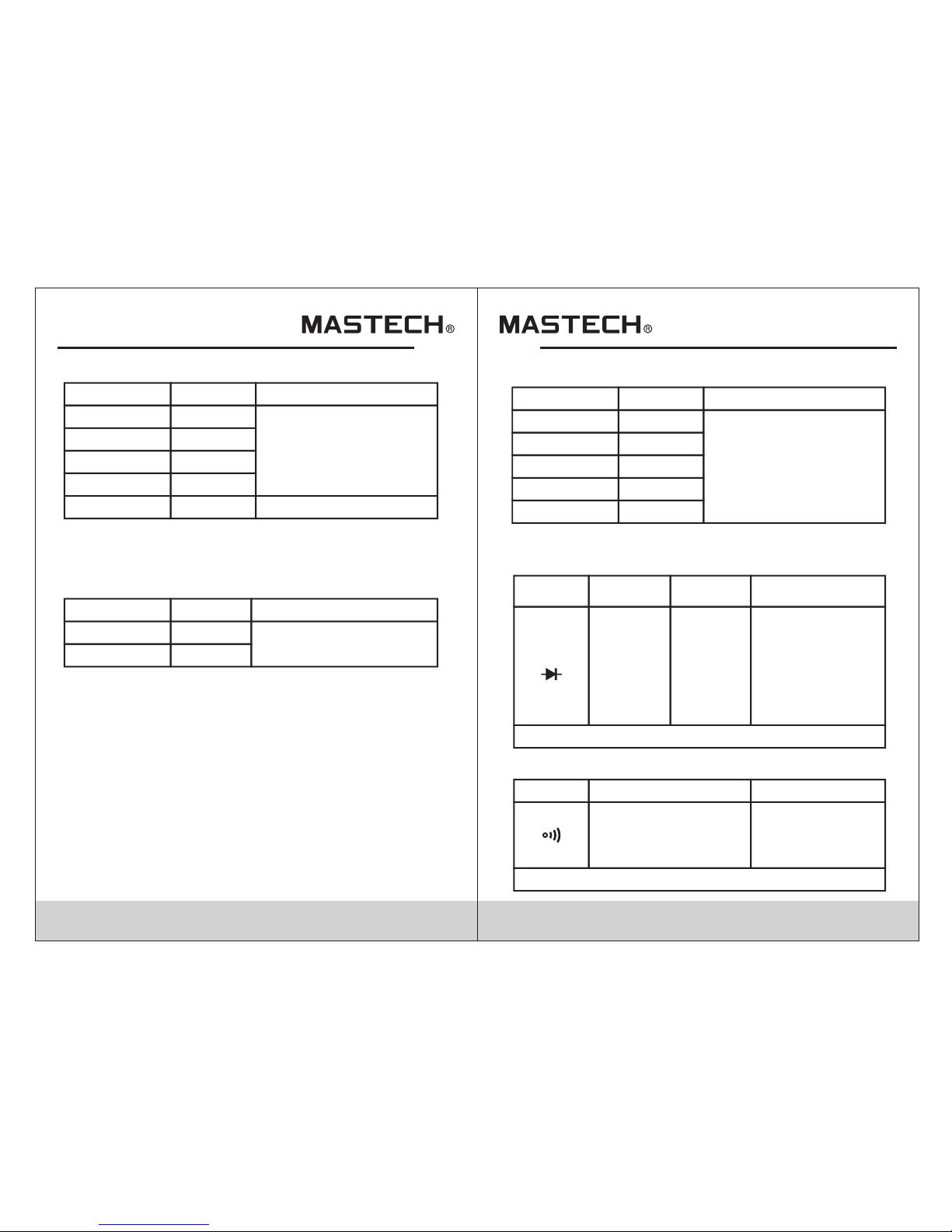
Forward DC current:
about 1mA; Reverse
DC voltage: about
2.5V. Display
approximation of
diode forward
voltage drop.
Diode
Measuring
range
Function Test EnvironmentResolution
0.001V
Diode Test
Overl oad prote ctio n: 250V DC or AC ( RMS)
When built-in buzzer
sounds, the resistance
to be tested is less than
about 60Ω.
Continuity Measurement
Function Test Environment
Description
Open circuit voltage:
about 2.5V
Overload protection: 250V DC or AC (RMS)
Page 10

15
16
Direct Current
Resolution
Accuracy
20mA
200mA 0.1mA
0.01mA
10mA10A
Measuring range
±(1.0% of reading +5 digits)
Overl oad prote ctio n: grade mA : Fuse (F20 0mA/ 600V)
prote ction; gr ade 10 A: Fuse (F1 0A/500V ) prot ection.
Maxim um input cu rren t: grade mA : 200mA DC or AC
RMS; gr ade 10A: 10 A DC or AC RMS
When me asured cu rren t is greate r than 2A, th e
conti nuous mea sure ment time c annot be no t more
than 2 mi nutes. Di scon nect the cu rrent and w ait 10
minut es before m akin g another m easurem ent.
±(2.0% of reading +10digits)
Battery Test
Resolution Built-in load resistance
12V
9V 0.01V
0.01V
0.001V1.5V
Measuring range
300Ω
1.8kΩ
36Ω
Overl oad prote ctio n: Fuse (F2 00mA/50 0V) pr otectio n;
Maintenance
This se ction pro vide s basic mai ntenanc e info rmation ,
inclu ding instruct ions for th e replace ment o f fuse and
batte ry. Do n ot try to rep air the met er unless you are
an expe rienced m aint enance pe rson with t he rel evant
calib ration, p erfo rmance te sting and m aint enance da ta.
To avoid in jury or damage to the meter, don't wet
the in ner p arts of the meter. Befo re opening the
case or bat tery cover, remove th e connecting
cabl e bet ween the test probe and the i nput signal.
Warning
General Maintenance
Regul arly clea n the me ter case wi th damp clo th and
a small a mount of de terg ent. Do not u se abrasi ves or
chemi cal solve nts. I f the input j ack becom es dir ty or
wet, it m ay affect the me asureme nt readings.
To clean in put socke t:
Turn off the meter and pul l out all the t est probes
from th e input jac k.
Remov e all dirt fr om the j acks.
Apply de tergent o r lubr icant to a ne w cotton ba ll
(such a s WD-40).
Clean e ach jack wi th a cot ton ball an d lubrica nt to
preve nt contam inat ion by mois ture in the s ocke t.
1
2
3
4
Replace Battery
To avoid in correct readings and po ssi ble electric
shoc k or pe rsonal injury, when “ ” app ear s on
the me ter d isplay, replace the batter y immediately.
To avoid el ectric shock or personal inj ury, before
open ing t he battery cover to repla ce battery, turn
off th e met er and make sure that the tes t probe is
disc onn ected from the measurem ent c ircuit.
Warning
Page 11

17
Replace Fuse
Pleas e follow th ese st eps to repl ace batte ry:
Turn off the power to the me ter.
Remov e all test pr obes f rom the inp ut jacks.
Loose n screws on t he bat tery cove r with
screw driver.
Remov e the batte ry cov er.
Remov e old batte ries .
Repla ce with two n ew AAA bat teries, p lacing
the pos itive and n egat ive ends in t heir corr ect
posit ions.
Repla ce the batt ery co ver and tig hten the sc rews.
1
2
3
4
5
6
7
To avoid el ectric shock or personal inj ury, before
open ing b ack cover to replace fuse , turn off the
meter and d isconnect the test prob e from the
measure ment circuit.
Warning
To replac e fuse:
Turn off the po wer to the me ter.
Remov e all test pr obes f rom the inp ut jacks.
Loose n screws on t he bac k cover wit h screwdr iver.
Remov e the back co ver.
Remov e the blown f use.
Repla ce with new f use wi th the same t ype.
Put the b ack cover a nd tig hten the sc rews.
1
2
3
4
5
6
7
HYS007065
 Loading...