

Page 1
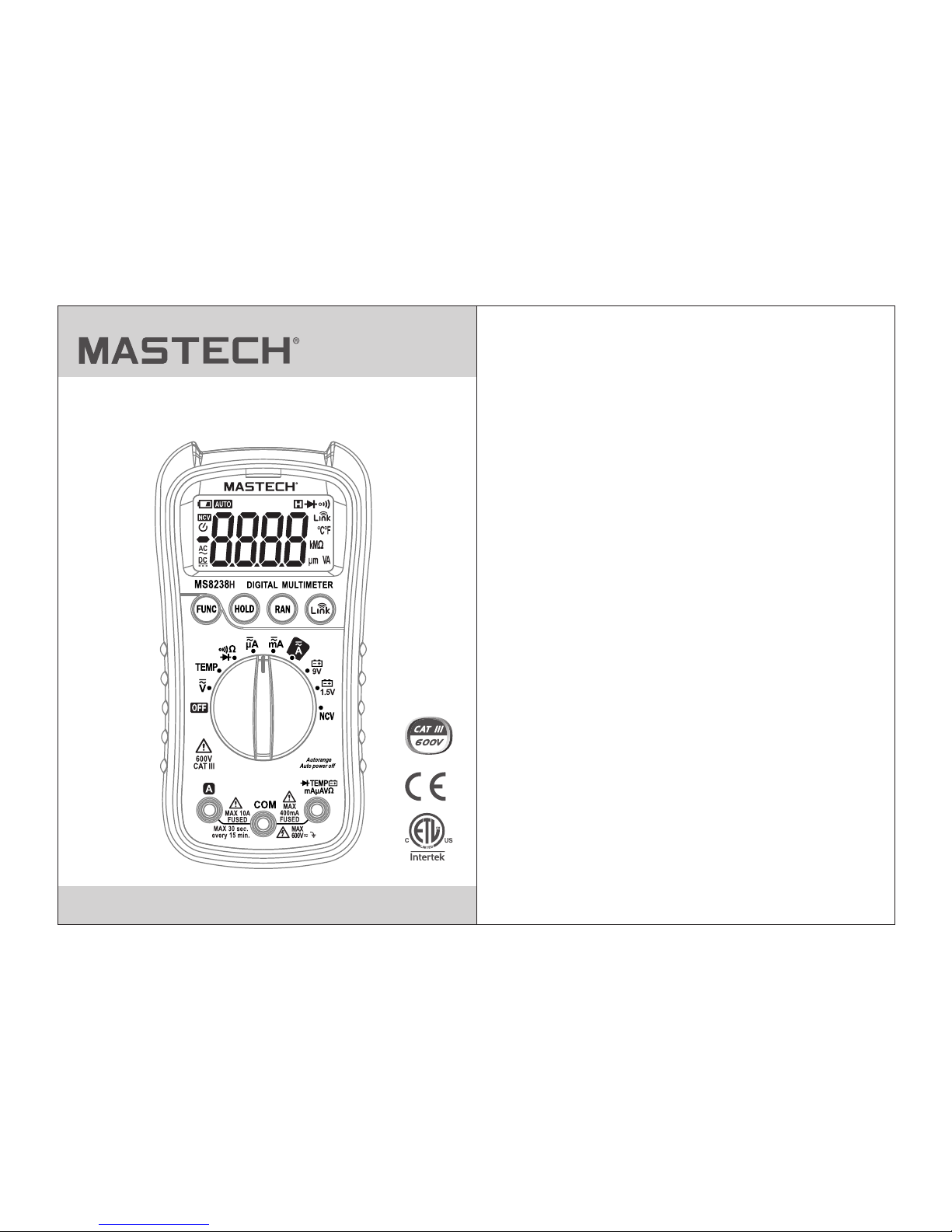
MS8238H
User's Manual
Digital Multimeter
Page 2

CONTENTS
2. Safety Information
2.1 Safety Standards
1. Overview
2.3 Precautions
2.4 Electrical Symbols
................................................................01
3. Description
3.1 Front Panel
3.2 Display
3.3 Button Funtions
4. Operating Instructions
4.1 AC/DC voltage
4.2 AC/DC current
3.4 Auto Power Off
5. Specifications
5.1 General Specifications
5.2 Technical Specifications
4.3 Resistance
4.4 Continuity
4.5 Diode test
4.6 Battery test
4.7 Temperature
6. Maintenance
6.1 General Maintenance
6.2 Replacing the Battery
6.3 Replacing the Fuse
4.8 Non-Contact Voltage
4.9 Wireless Operation
CONTENTS
................................................01
................................................01
........................................................02
...............................................04
..........................................................05
.........................................................05
................................................................06
..................................................07
...................................................07
.......................................08
...................................................08
...................................................08
........................................................09
..........................................................10
........................................................10
......................................................11
..........................................11
...............................................11
.....................................................12
.......................................12
.....................................13
.......................................................16
.........................................16
.........................................17
............................................17
..........................................18
6.4 Replacing the Probe
7. Accessories
..........................................................09
........................................................18
2.2 FCC Statement
...................................................02
Page 3
01
02
WARNING
1.Overview
The multimeter is a small, safe and reliable 3 digit handheld auto
ranging multimeter. This meter can measure AC/DC voltage, AC/DC
current, resistance,diode, continuity, battery test, temperature and
non-contact voltage tests, along with Wireless communication
capabilities.This tool is ideal for professionals and hobbyists alike.
2. Safety Information
2.1 Safety Standards
The multimeter meets the following safety standards:
EN/UL/CSA61010-1,61010-2-030,61010-2-033for electronic testing
instruments. This meter meets CAT III 600V installations and a pollution
degree of 2.
• The protection provided by the meter can only be ensured if all safety
procedures are strictly followed.
• The safety symbols on the meter are to advise of potential dangerous
situations.Caution is required when measuring close to the meter’s
safety limits.
• Never exceed the protection limit values indicated in the specifications
for each range of measurement.
• Check the test leads for cracks or exposed wires before using the
meter.Replace if necessary.
• Ensure the meter works properly by testing a known voltage source
first. If not working properly, the protective equipment may be
damaged; have the meter serviced before using.
To avoid electrical shock or personal injury, please read all
safety information,warnings and precautions before using
the meter.
3
4
2.2 FCC Statement
This device complies with part 15 of the FCC Rules. Operation is
subject to the following two conditions: (1) This device may not cause
harmful interference, and (2) this device must accept any interference
received, including interference that may cause undesired operation.
This equipment has been tested and found to comply with the limits for
a Class B digital device, pursuant to part 15 of the FCC Rules. These
limits are designed to provide reasonable protection against harmful
interference in a residential installation. This equipment generates, uses
and can radiate radio frequency energy and, if not installed and used in
accordance with the instructions, may cause harmful interference to
radio communications. However, there is no guarantee that interference
will not occur in a particular installation. If this equipment does cause
harmful interference to radio or television reception, which can be
determined by turning the equipment off and on, the user is encouraged
to try to correct the interference by one or more of the following
measures:
- Reorient or relocate the receiving antenna.
- Increase the separation between the equipment and receiver.
- Connect the equipment into an outlet on a circuit different from that to
which the receiver is connected.
- Consult the dealer or an experienced radio/TV technician for help.
Caution:
Any changes or modifications not expressly approved by the party
responsible for compliance could void the user's authority to operate the
equipment.
• Check the meter for damage before use.Do not use if any damage is
observed.
The special attention should be paid when using the meter
because the improper usage may cause electric shock and
damage the meter. The safety measures in common safety
regulations and operating instruction should be complied
with when using. In order to make fully use of its functions
and ensure safe operations please comply with the usage in
this section carefully.
WARNING
2.3 Precautions
To avoid electrical shock or personal injury, observe and follow all safety
precautions
Page 4
03
04
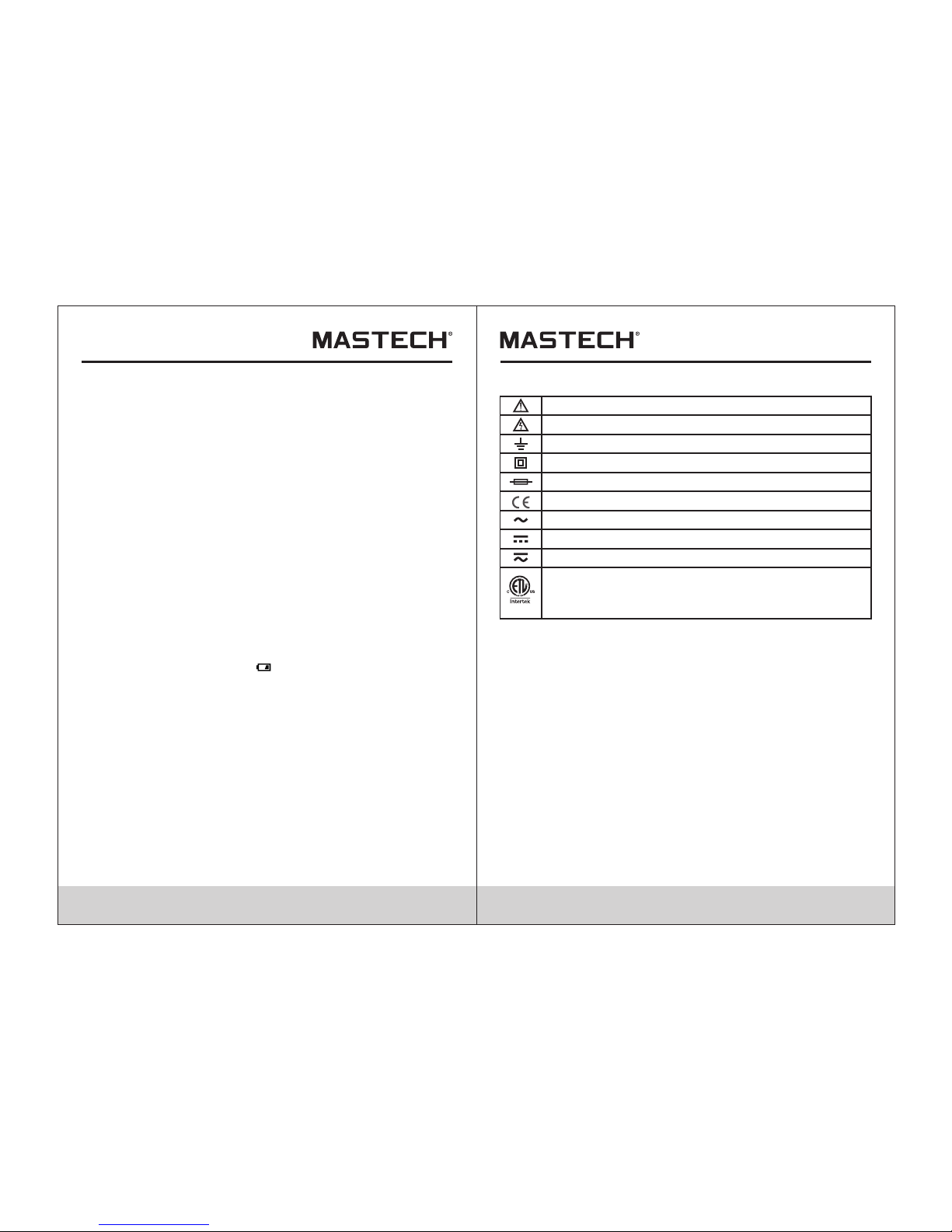
2.4 Electrical Symbols
AC & DC (Both direct and Alternating Current)
Important safety information.
High voltage with danger.
Ground.
Double Insulation (Class II safety equipment).
Fuse must be replaced as per the specification herein.
Accord with the related EU laws and regulations
AC (Alternating Current)
DC (Alternating Current)
Conforms to UL STD. 61010-1, 61010-2-030 and
61010-2-033; Certified to CSA STD. C22.2, NO. 61010-1,
61010-2-030 and 61010-2-033
CAT III : MEASUREMENT CATEGORY III
is applicable to test and measuring circuits connected to the distribution
part of the building’s low-voltage MAINS installation.
• For continued protection against fire, replace fuse only with the
specified voltage and current ratings listed in the manual.
• If the equipment is used in a manner not specified by the manufacturer,
the protection provided by the equipment may be impaired.
• Measure known voltage with the meter to verify that the meter is
working properly. If the meter is working abnormally, stop using it
immediately. A protective device may be damaged. If there is any
doubt, please have the meter inspected by a qualified technician.
• Never measure voltages that may exceed the protection limit indicated
on the meter.
• Always be careful when working with voltages above 60V DC or 30V
AC rms. Keep fingers behind the probe barriers when making voltage
measurements.
• Make sure the test leads are in the correct input jacks before
measurement.
• Do not expose the meter to explosive gas, dust or vapor.
• When connecting the test leads to a measurement circuit, connect the
common lead first, then the live lead. Reverse when disconnecting.
• Turn off power to circuit and discharge all capacitors before making
resistance, continuity or diode measurements.
• In order to avoid incorrect DC voltage readings, check the circuit for
AC voltage first, then put the meter in the appropriate DC voltage
range.
• Turn off circuit power and check fuses before connect the leads when
measuring current. Turn circuit power on after making connection.
• Never use the meter unless the back cover is in place and fastened
securely.
• When the low battery indicator “ ” is displayed, replace the battery.
The accuracy of the meter cannot be guaranteed while the low battery
indicator is on.
• Before opening the case, always disconnect test leads from all
energized circuits.
Page 5

05
06
3.2 Display
3 Description and Usage
3.1 Front Panel
1.LCD display
2.Wireless
communication button
3.Range button
4.Function button
5.Data hold button
6.Rotary switch
7.10A input jack
8.Common jack
9.Input jack
(all functions except current
greater than 400mA)
1
4
5
6
2
3
7
9
8
Direct Current/Voltage
Alternating Current/Voltage
Negative Value
Wireless Communication indicator
Auto Power Off
Low Battery
Auto Range Active
Main Display
Data Hold
Diode Test
Continuity Test
Non-contact Voltage
Measurement Units
Page 6

WARNING
Never measure open-circuit voltages exceeding 600V between
the input terminals and ground to prevent injury or damage to
the meter
07
08
4. Operating Instructions
WARNING
Do not measure voltages higher than 600V DC or ACrms to
prevent damage to the meter or personal injury
4.1 AC/DC voltage measurement
•
• Press “FUNC” to switch between AC and DC voltage.
• Connect the red test lead to the input jack and the black lead to the
COM jack.
• Connect the leads to the circuit under test and read the measurement
on the display. Observe polarity for DC measurements. In manual
mode, If “OL” is display it means the measurement has exceeded the
current range. Increase the selected range and measure again.
Set the rotary switch to the AC/DC voltage position.
4.2 AC/DC current measurementrent
• Turn off power to the circuit. Allow all capacitors to discharge.
• Set the rotary switch to the appropriate AC/DC current range.
• Press “FUNC” to switch between AC and DC current.
• Depending on the current to be measured, connect the red test lead to
either the input or 10A jack and the black lead to the COM jack.
• Break the circuit and connect the leads in series with the circuit (black
lead on the lower voltage side).
• Turn circuit power on and read the measurement on the display. If “OL”
is display, it means the measurement has exceeded the current range.
Move the rotary switch to a higher range.
3.3 Button Functions
FUNC button:
• Press “FUNC” to switch between AC/DC or between function in a
rotary switch position.
HOLD button:
•
• Press “HOLD” again to release the hold.
Press “HOLD” to keep the current reading on screen. “H” symbol will
appear on the display.
RAN button:
• Press “RAN” to switch to manual range.Each press of the button will
switch to the next highest range, until reaching the highest range
where it will switch to the lowest range.
• Hold “RAN” to return to auto range.
3.4 Auto Power Off Function
•
• To turn the meter back on, press “FUNC”.
After 15 minutes of non-use the meter will automatically turn itself off.
button:
• With the rotary switch in any position other than OFF, press to
enable the Wireless communication function of the meter. Open the
app (iOS or Android) on the mobile device to be used and search for
the multimeter and establish a connection. Once connected, the app
will mirror the display of the meter and show any measurement being
performed. Press again to disconnect the meter from the mobile
device.
• To deactivate the auto power off function, hold down “FUNC” when
turning on the meter. will no longer be displayed.
Page 7

09
10
WARNING
To prevent injury or damage to the meter,turn off power to
circuit and discharge all capacitors fully before making
continuity measurements.
4.5 Diode test
• Turn off power to the circuit. Allow all capacitors to discharge.
• Set the rotary switch to the multi-function position. Press “FUNC” once
to enter diode mode.
• Connect the red test lead to the input jack and the black lead to the
COM jack.
• Connect the red test lead to the anode (+) and the black lead to the
cathode (-) of the diode and read the measurement on the display.
The meter will display “OL” if the connection is reversed.
4.6 Battery test
• Connect the red test lead to the input jack and the black lead to the
COM jack.
• Connect the red test lead to the positive (+) end and the black lead to
the negative (-) end of the battery and read the measurement on the
display.
• Set the rotary switch to the appropriate battery test range.
To prevent injury or damage to the meter,do not connect the
meter to a battery with a voltage rating exceeding 60V AC or
30V DC.
WARNING
WARNING
To prevent injury or damage to the meter,turn off power to
circuit and discharge all capacitors fully before making
diode measurements.
Check fuses before making current measurements.Make sure
to use correct input jicks to prevent damage to the meter.
4.3 Resistance measurement
• Set the rotary switch to the multi-function position. The default function
is resistance.
• Connect the red test lead to the input jack and the black lead to the
COM jack.
• Connect the leads to the circuit under test and read the measurement
on the display.
• Turn off power to the circuit. Allow all capacitors to discharge.
Tips for measuring resistance:
• For increased accuracy when measuring low resistances, short the
test leads, record the value displayed, then connect the leads to the
circuit and subtract the shorted value from the circuit measurement.
• When the leads are disconnected from the circuit under test, “OL” will
be displayed on the screen.
• In-circuit resistance is usually different from a resistors rating due to
the fact that the meter’s test current flows in parallel with the circuit.
NOTE
To prevent injury or damage to the meter , turn off power to
circuit and discharge all capacitors fully before making
resistance measurements.
WARNING
4.4 Continuity measurement
• Set the rotary switch to the multi-function position. Press “FUNC” twice
to enter continuity mode.
• Connect the red test lead to the input jack and the black lead to the
COM jack.
• Connect the leads to the circuit under test. If the measured resistance
is less than 50Ω, the buzzer will sound.
• Turn off power to the circuit. Allow all capacitors to discharge.
Page 8

11
12
5. Specifications
5.1 General Specifications
When battery voltage drops below
shown on the display
Polarity Indication
Display automatically displays “-”
Function
Range
Max. Input between terminals
and earth ground
600V DC or AC T-RMS
Fuse Protection
Sample Rate Approx. 3 times/sec.
Display
3 digit LCD display
Overload Indication
Display shows “OL”
Low Battery Indication
Temperature
coefficient
0.1xaccuracy/°C (>18°C or <28°C)
Power Supply
DC 9V (NEDA 1604, 6F22 or 006P)
Size(LxWxH)
Approx. 148x73.5x50mm
weight
Approx. 232g
Safety Rating CAT III 600V, pollution degree of 2
Operating Altitude
≤2000m
Operating Temperature/
Humidity
0~40°C, <80% RH
µA/mA ranges: F 400mA H 600V
10A range: F 10A H 600V
Storage Temperature/
Humidity
-10~60°C, <70% RH, remove battery
normal operating voltage,“ ”is
Wireless Communication
Distance
Indoor/Outdoor: ≤10m
iOS: 7.0 and above
Android: 4.3 and above
Supported App OS
4.7 Temperature measurement
• Connect the positive end of the K-type thermocouple to the input jack
and the negative end to the COM jack.
• Place the tip of the thermocouple to the surface of the object to be
tested and read the measurement on the display.
• Set the rotary switch to the temperature position. Press “FUNC” to
switch between Celsius and Fahrenheit.
To avoid injury or damage to the meter,do not move the rotary
switch to the temperture position while measuring voltages
exceeding 30V.
WARNING
4.8 Non-Contact Voltage (NCV) measurement
• Move the top of the meter toward the voltage source. If voltage is
detected (>100V AC), the meter will beep and the NCV indicator will
flash. The closer to the voltage source the meter is, the faster the
meter will beep/flash.
• Even without indication, voltage may still be present. Do not rely
solely on NCV detection to determine the presence of voltage.
Detection could be impaired by socket design, insulation thickness, or
other factors.
• Set the rotary switch to the NCV position.
Note:
• External interference sources could mistakenly trigger NCV indication.
4.9 Wireless Operation
• Open the app (iOS or Android) on the mobile device to be used and
search for the multimeter and establish a connection. Once connected,
the app will mirror the display of the meter and show any measurement
being performed.
• Press again to disconnect the meter from the mobile device.
• With the rotary switch in any position other than OFF, press to
enable the Wireless communication function of the meter.
3
4
Page 9

13
14
5.2.3 Resistance
Resolution
Accuracy
400Ω
4kΩ
0.1kΩ
0.001kΩ
0.1Ω
0.01kΩ
0.001MΩ
40kΩ
400kΩ
4MΩ
Range
±(0.8% of reading +3digits)
0.01MΩ40MΩ
If measured resistanceis less
than 50Ω, buzzer will sound
5.2.5 Continuity
Function Description
Description
Open circuit voltage:
~1V
5.2.4 Diode Test
Display shows
forward voltage drop
Function
Description
Resolution
3V
Diode Test
Range
1mV
±(1.2% of reading +3digits)
5.2 Technical Specifications
Accuracy: ±(% of reading + digits) at 18°C~28°C with a relative humidity
of <80%; guaranteed for a period of one year.
Resolution
Accuracy
4V
40V
0.01V
0.001V
5.2.2 AC Voltage
Range
±(1.0% of reading +10 digits)
5.2.1 DC Voltage
Input impedance: 10MΩ
Max. input voltage: 600V DC or AC T-RMS.
Resolution
Accuracy
400mV
4V
0.1V
0.001V
0.1mV
0.01V
1V
40V
400V
600V
±(0.8% of reading +5 digits)
Range
±(0.5% of reading +2 digits)
400V
600V
1V
0.1V
Input impedance: 10MΩ
Max. input voltage: 600V DC or AC T-RMS.
Frequency Response: 40~400Hz, T-RMS response
400m V 0.1m V
Page 10

15
16
5.2.8 Temperature
Resolution
Accuracy
-20~1000°C 1°C
1°F
-4~1832°F
Range
±(2.0% of reading +2 digits)
• Use a damp cloth to regularly clean the outside of the meter.Do not
use abrasives or chemical solvents. Dirty or damp input jack can
adversely affect readings.
• To clean input jacks, follow the following steps:
1.Turn off the instrument and remove the test leads.
2.Clear any dirt or other particles on the input jacks.
3.Use a cotton ball/swab with a lubricant (i.e. WD-40) to clean off the
contacts of the input jacks.
4.Use a separate cotton ball/swab for each jack to prevent
cross-contamination.
6. Maintenance
6.1 General Maintenance
This section provides basic information on maintaining the meter, such
as replacing fuses and the battery. Only experienced and authorized
personnel should make repairs to the meter.
To avoid injury or damage to the meter,do not allow moisture
inside the case and remove test leads before opening battery
cover.
WARNING
±(2.0% of reading +4 digits)
5.2.6 DC Current
Resolution
Accuracy
400µA 0.1µA
1µA4000µA
Range
±(1.0% of reading +10digits)
±(2.0% of reading +8digits)
40mA
400mA
10A
0.01mA
0.1mA
10mA
Overload protection: mA jack: F 400mA H 600V fuse
10A jack: F 10A H 600V fuse
Max input current: mA jack: 400mA DC or AC T-RMS
10A jack: 10A DC or AC T-RMS
When measuring current exceeding 2A, do not measure for longer than
2 minutes continuously. Wait 10 minutes to continue measurement.
5.2.7 AC Current
Resolution
Accuracy
400µA
0.1µA
1µA
4000µA
Range
±(1.2% of reading +5digits)
40mA
400mA
10A
0.01mA
0.1mA
10mA
±(2.0% of reading +8digits)
Overload protection: mA jack: F 400mA H 600V fuse
10A jack: F 10A H 600V fuse
Frequency Response: 40~400Hz, T-RMS
Max input current: mA jack: 400mA DC or AC T-RMS
10A jack: 10A DC or AC T-RMS
When measuring current exceeding 2A, do not measure for longer than
2 minutes continuously. Wait 10 minutes to continue measurement.
Page 11

17
6.4 Replacing the Probe
Ifinsulationonprobeisdamaged,replaceit.
WARNING
Use meet EN 61010-031 standard, rated CAT III 600V, 10A or
better probe.
7. Accessories
Test Leads
1set
Package
1pcs
9V Battery
1pcs
User's Manual
1pcs
K type thermocouple
1pcs
6.2 Replacing the Battery
WARNING
To avoid false readings and potential dangerous situations,
replace the battery immidately when the “ ” symbol
appears. Turn off the meter and disconnect the test leads
before opening the battery cover to prevent electrical shock
and personal injury.
Use the following steps to replace the battery:
1.Turn off the meter.
2.Remove test leads.
3.Unscrew and remove battery cover from back of meter.
4.Replace used battery with a new 9V battery.
5.Replace battery cover and fasten securely.
6.3 Replacing the Fuse
WARNING
Turn off the meter and disconnect test leads before opening
back cover to avoid electical shock and personal injury.
Use the following steps to replace the fuses:
1.Turn off the meter.
2.Remove test leads.
3.Remove outer holster.
4.Unscrew and remove back cover from the meter.
5.Replace blown fuse(s) with same amp/voltage ratings.
6.Replace back cover and fasten securely.
7.Replace outer holster.
18
1
2
3
4
5
Page 12

R-00-05-1807
 Loading...