

Page 1
MS8238G
User's Manual
Digital Multimeter
MS8238G
CAT .I I
600V
Page 2
CONTENTS
2. ....... ........... ................ 1Safety In formation
2.1 Safety S tandards................................1
1.Overview .................................................1
2.2 Pre cau tions......................................2
Warning
1.Over view
To avoi d electrical shoc k or pe rsonal injur y,
pleas e rea d all safety inform ation,warning s and
preca uti ons before using th e meter.
The MS8 238 G is a small, safe a nd re liable 3 1/2 dig it
handh eld m ultimeter. This meter can me asu re AC/DC
volta ge, D C current, res ist ance, diode, c ont inuity and
batte ry te st and non-con tac t voltage test s. This tool is
ideal f or pr ofessional s and h obbyists ali ke.
2. Safet y Informati on
2.1 Saf ety S tandards
2.3 Ele ctr ical Symbols ..............................3
3. ....... ........... .........4Descr iption and Usage
3.1 Front Pa nel.......................................4
3.2 Dis pla y ...........................................5
3.3 Usi ng th e Meter..................................6
4. ....... ........... ................ ....10Spe cifications
4.1 Gen era l Specificat ion s........................10
4.2 Techn ica l Specificat ion s ......................11
5. ....... ........... ................ .......13Maintena nce
5.1 Gen era l Maintenanc e .........................13
5.2 Rep lac ing the Batter y and F uses.............14
5.3 Rep lac ing the Probe ..........................14
01
The MS8 238 G meets the safe ty st andards UL
CSA C22. 2 No. 61010-1, CAT II 600V and a p oll ution
degre e 2.
61010 -1,
• The pr otection pro vid ed by the meter ca n onl y be
ensured if a ll safety proc edu res are strict ly fo llowed.
• The sa fety symbols o n the m eter are to advi se of
potentia l dangerous si tua tions.Caut ion i s required
when me asu ring close to th e met e’s safe ty li mits.
• Never e xce ed the protect ion l imit values in dic ated in
the specif ications for e ach r ange of measur eme nt.
WARNIN G
The sp ecial a ttent ion s hould b e paid wh en usin g the met er
beca use the i mprop er us age may c ause el ectri c shock a nd
dama ge the me ter . Th e saf et y mea sures i n commo n safet y
regu latio ns an d op era ting in struc tion sh ould be c ompli ed wi th
when u sing. I n order t o mak e fu lly u se of its f uncti ons and
ensu re safe o perat ion s pleas e compl y with th e usage i n this
sect ion car efull y. If t he e qui pment i s used in a m anner n ot
spec ified b y the man ufa cture r, the pro tecti on prov ided by t he
equi pment m ay be i mp air ed.
Page 3
02
03
2.2 Pre cau tions
• To avoid e lec trical shock o r per sonal injury, observe
and fol low a ll safety prec aut ions
• Check t he me ter for damage b efo re use. Do not use i f
any dam age i s observed.
• Check t he te st leads for cra cks o r exposed wire s bef ore
using the me ter. Replace if n ece ssary.
• Ensur e the m eter works pro per ly by testing a kn own
voltage so urce first.If not w orking prope rly, the
prote cti ve equipment m ay be d amaged; have t he me ter
serviced b efore using.
• Never m eas ure voltages t hat m ay exceed the pr ote ction
limit i ndi cated on the met er.
• Always b e car eful when work ing w ith voltages a bov e
60V dc or 30V ac r ms. Keep finge rs be hind the probe
barri ers w hen making vol tag e measuremen ts.
• Make su re th e test leads are i n the c orrect input j ack s
before mea surement.
• Do not ex pos e the meter to exp los ive gas, dust or v apo r.
• When co nne cting the test l ead s to a measureme nt
circu it, c onnect the com mon l ead first, the n the l ive lead.
Rever se wh en disconnec tin g.
• Turn off power to circu it an d discharge al l cap acitors
before mak ing resistan ce, c ontinuity or d iod e
measu rem ents.
• In orde r to av oid incorrec t DC vo ltage readin gs, c heck
the circui t for AC voltage fi rst , then put the meter in t he
appro pri ate DC voltage r ang e.
• Turn off circuit powe r and c heck fused bef ore c onnect
the lea ds wh en measuring c urr ent.Turn circuit po wer
on after mak ing connecti on.
• Never u se th e meter unless t he ba ck cover is in pla ce
and fasten ed securely.
• When th e low b attery indic ato r“ ”is display ed, r eplace
the batter y.The accura cy of the meter canno t be
guara nte ed while the low b att ery indicato r is on .
• Befor e ope ning the case, a lwa ys disconnec t tes t leads
from all ene rgized circu its .
• For con tin ued protecti on ag ainst fire, re pla ce fuse only
with the spe cified volta ge an d current rati ngs l isted in
the manual .
2.3 Electr ical Symbols
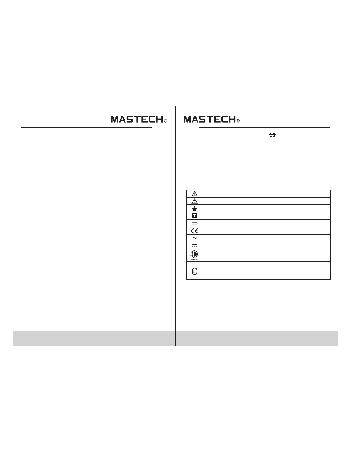
Important safety information. Read the manual.
High voltage with danger.
Ground.
Double Insulation (Class II safety equipment).
Fuse m ust be re place d as pe r th e spe cific ation h erein .
Acco rd with t he rela ted E U laws an d regul ation s
AC (Al terna ting Cu rre nt)
DC (Direct Current)
Conf orms to U L STD 61 010 -1 ;
Cert ified t o CSA STD C2 2.2 N O. 610 10-1
This p roduc t has bee n tes te d to th e requi remen ts
of CAN /CSA C22 .2 NO.6 101 0-1,s econd e ditio n,
incl uding Am end me nt 1.
CAT II (Measurement category ll): it is for measurements
performed on circuits directly connected to the low voltage
installation.
Page 4

04
05
3 Descri ption and Usa ge
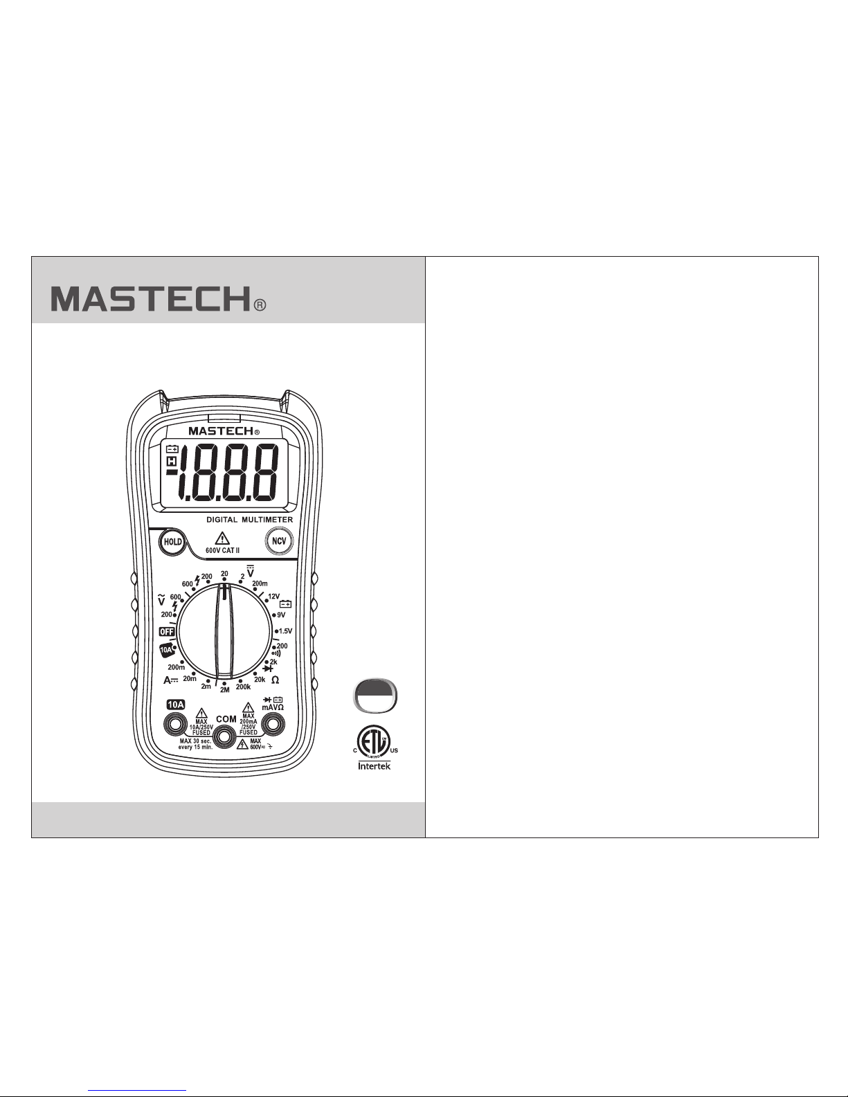
3.1 Front Pa nel
1.LCD d isp lay
2.Dat a hol d button
3.Rot ary s witch
4.10A in put j ack
5.Com mon j ack
6.Inp ut ja ck (all functi ons e xcept curren t gre ater than
200mA)
7.Non -co ntact voltag e (NC V) button
8.Non -co ntact voltag e (NC V) indicator
1
2
3
4
5
6
3.2 Dis pla y
1.Low b att ery indicato r
2.Dat a hol d
3.Mea sur ement displa y
4.Pol ari ty indicator
1 2 3
4
MS8238G
8
7
Page 5

06
07
3.3 Usi ng th e Meter
3.3.1 D ata H old
The dat a hol d function wil l hol d the current re adi ng on
the dis pla y.
• Press the “H OLD” button to hold t he current rea din g.
“H” symbol w ill appear on th e dis play.
• Press the “H OLD” button to rele ase the hold.
3.3.2 A C/D C voltage meas ure ment
•
voltage ra nge.
• Conne ct th e red test lead to t he in put jack and the b lac k
lead to the CO M jack.
• Conne ct th e leads to the cir cui t under test and r ead t he
measu rem ent on the displ ay. Observe po lar ity for DC
measu rem ents.
Set the rota ry switch to the appr opriate AC or DC
Warning
Do not measu re voltages highe r than 600V DC
or AC rms to perev ent d amage to the met er or
perso nal i njury.
3.3.3 D C cur rent measure men t
• Turn off power to the cir cui t. Allow all capa cit ors to
disch arg e.
• Set the rota ry switch to the appr opriate DC cur ren t range.
• Depen din g on the current t o be me asured, conn ect t he
red test lea d to either the in put o r 10A jack and the bl ack
lead to the CO M jack.
• Break the ci rcuit and conn ect t he leads in seri es wi th the
circuit (b lack lead on the l owe r voltage side ).
• Turn cir cui t power on and rea d the m easurement o n the
displ ay. If “OL” is displa y, it means the me asurement
has exceed ed the current r ang e.Move the rot ary s witch
to a high er ra nge.
Warning
Never m eas ure open-cir cui t voltages exc eed ing
250V be twe en the input termin als and ground to
preve nt in jury or damage to the m eter.
NOTE
Check f use s before makin g cur rent measure men ts,
Make su re to u se correct inp ut ja cks to prevent
damag e to th e meter.
Page 6

08
09
3.3.4 R esi stance measu rem ent
• Turn off power to the cir cui t. Allow all capa cit ors to
disch arg e.
• Set the rota ry switch to the appr opriate resi sta nce range.
• Conne ct th e red test lead to t he in put jack and the b lac k
lead to the CO M jack.
• Conne ct th e leads to the cir cui t under test and r ead t he
measu rem ent on the displ ay.
Tips f or measuring r esi stance:
• In-ci rcu it resistanc e is us ually diffe rent from a resi sto rs
ratin g due t o the fact that the met er’s t est current fl ows
in para lle l with the circu it.
• For inc rea sed accuracy w hen m easuring low
resis tan ces, short the test l eads, record the va lue
displ aye d, then connec t the l eads to the circ uit a nd
subtract t he shorted val ue fr om the circuit m eas urement.
• When th e lea ds are disconn ect ed from the circ uit u nder
test, “OL” w ill be display ed on t he screen.
Warning
To prev ent injury or damag e to th e meter,turn
off power to c ircuit and discha rge a ll capacitio rs
fully befo re making resista nce measurem ent s.
3.3.5 C ont inuity measurem ent
• Turn off power to the cir cui t. Allow all capa cit ors to
disch arg e.
• Set the rota ry switch to the cont inuity posit ion .
• Conne ct th e red test lead to t he in put jack and the b lac k
lead to the CO M jack.
• Conne ct th e leads to the cir cui t under test.I f the
measu red r esistance is l ess t han 50Ω, the buz zer
will so und .
Warning
To prev ent injury or damag e to th e meter,turn
off power to c ircuit and discha rge a ll capacitio rs
fully befo re making resista nce measurem ent s.
3.3.6 D iod e test
Turn off p owe r to the circuit . Allo w all capacito rs to
disch arg e.
• Set the rota ry switch to the diod e position.
• Conne ct th e red test lead to t he in put jack and the b lac k
lead to the CO M jack.
• Conne ct th e red test lead to t he an ode (+) and the bl ack
lead to the ca thode (-) of the d iod e and read the
measu rem ent on the displ ay.The meter w ill d isplay “OL”
if the conne ction is rever sed .
Warning
To prev ent injury or damag e to th e meter,turn
off power to c ircuit and discha rge a ll capacitio rs
fully befo re making resista nce measurem ent s.
3.3.7 B att ery test
• Set the rota ry switch to the appr opriate batt ery t est range.
• Conne ct th e red test lead to t he in put jack and the b lac k
lead to the CO M jack.
• Conne ct th e red test lead to t he po sitive (+) end a nd th e
black l ead t o the negative ( -) en d of the battery a nd re ad
the measur ement on the dis pla y.
Warning
To prev ent injury or damag e to th e meter,do not
connent th e meter to a battery wi th a voltage rating
excee din g 60V AC or 3 0V DC
Page 7

10
11
4. Speci fications
4.1 Genera l Specificat ion s
When b atter y volta ge dr ops bel ow
norm al oper ati ng v olt age,“ ” is
show n on the di spl ay
Pola rity In dicat ion
Disp lay aut oma ti cal ly disp lays “- “
Powe r Sourc e
Function
Range
Safe ty Rati ng
CAT II 600V; pollution degree: 2
Oper ating Al titud e
≤2000 m
Operating Temperature/
Humidity
0~40 °C, <80 % RH
Stor age Tempera tur e/
Humi dity
-10~ 60°C, < 70% RH, r emo ve batt ery
Max. I nput be tween
term inals a nd ea rt h
grou nd
600V D C or AC rms
Fuse P rotec tion
mA 250m A 250V
10A ran ge: Fus e F 10A 250V
rang e: Fuse F H
H
Samp le Rate Appr ox. 3 tim es/se c.
Disp lay
3 ½ digi t LCD dis pla y
Over load In dicat ion
Disp lay sho ws “OL”
Low Ba ttery I ndica tio n
4.2 Tec hnical Specific ations
Accuracy: ±(% of reading + digits) at 18°C~28°C with a
relative humidity of <80%; guaranteed for a period of one year.
4.2.3 Resistance
Resolution
Accuracy
200Ω
2kΩ
0.1kΩ
0.001kΩ
0.1Ω
0.01kΩ
0.001MΩ
20kΩ
200kΩ
2MΩ
Measuring range
±(0.8% of reading +4 digits)
Overl oad p rotection: 2 50V D C or AC (RMS)
Resolution
Accuracy
200V
600V
1V
0.1V
4.2.2 AC Voltage
Max. in put v oltage: 600V D C or AC rm s.
Frequ enc y Response: 40 ~40 0Hz, sine wave r ms
(avg. r esp onse)
Measuring range
±(1.0% of reading +5 digits)
4.2.1 DC Voltage
Max. in put v oltage: 600V D C or AC rm s.
Resolution
Accuracy
200mV
2V
0.1V
0.001V
0.1mV
0.01V
1V
20V
200V
600V
±(0.8% of reading +5 digits)
Measuring range
±(0.5% of reading +2 digits)
1x 9V battery (NEDA 1604, 6F22 or 006P)
Page 8

4.2.6 DC Current
Resolution
Accuracy
2mA 0.001mA
10mA10A
Measuring range
±(2.5% of reading +3digits)
If measure d resistance
is less than 4 0Ω,
buzze r wil l sound
4.2.5 Continuity
Function Descr ipt ion
Description
Open ci rcu it
volta ge: 2 .9V
Overload protection: 250V DC or AC (RMS)
Forwa rd DC c urrent: 1mA
Rever se DC v oltage: 2.9V
Displ ay sh ows forward
volta ge dr op
4.2.4 D iod e Test
Function
Descr ipt ionResolution
0.001 V
Diode Test
Overl oad p rotection: 2 50V D C or AC (RMS)
12
13
Overl oad p rotection: m A jack : F 250mA 250V fu se
10A jack : F10 A 250V fu se
Max inp ut cu rrent: mA jack: 2 00m A DC
10A jack : 10A DC
When me asu ring current e xce eding 2A, do not m eas ure
for lon ger t han 2 minutes co nti nuously. Wait 10 m inu tes
to continu e measuremen t.
H
H
4.2.7 B att ery Test
Overl oad p rotection: F 250 mA 250V fuseH
20mA 0.01mA
200mA 0.1mA
±(0.8% of reading +3 digits)
5. Maint enance
5.1 Genera l Maintenance
This se cti on provides ba sic i nformation o n mai ntaining
the meter, su ch as replacin g fus es and the batte ry. Only
exper ien ced and author ize d personnel sh oul d make
repai rs to t he meter.
Warning
To avoi d inj ury or damage to t he me ter,do not allo w
moisture i nside the case and re move test leads
befor e ope ning battery cove r.
• Use a dam p clo th to regularl y cle an the outside o f the
meter. Do not u se abrasives o r che mical solven ts. Dirty
or damp i npu t jack can adver sel y affect r ead ings.
• To clean i npu t jacks, follo w the f ollowing ste ps:
1.Turn off the i nstrument an d rem ove the test lea ds.
2.Clea r any d irt or other par tic les on the input j ack s.
3.Use a co tto n ball/swab wi th a lu bricant (i.e . WD- 40) to
clean o ff the contac ts of t he input jacks .
4.Use a se par ate cotton bal l/s wab for each jac k to
prevent cr oss-contam ina tion.
4.2.8 N CV Test
• Hold do wn th e NCV button and m ove t he NCV sensor
at the top of th e unit next to the obje ct being tested.
• When vo lta ge is detected ( >110V AC rms) the b uzz er
will so und a nd the NCV indic ato r will flash.
Resolution
Accuracy
12V
0.01V
0.01V9V
Position
±(0.8% of reading +7 digits)
±(0.8% of reading +7digits)
1.5V 0.001V
±(3.0% of reading +5digits)
Page 9

14
00-05-0000
5.2 Rep lac ing the Batter y and F uses
5.3 Rep lac ing the Probe
1. Und er norm al cond iti ons, it i s unnec essar y to repl ace the f use .
Don' t repla ce it unt il th e pr obe s are unp lugge d and the p ower is
shut d own. Take out t he tw o sc rew s of the re ar cove r to remo ve
the ho using .
2. The spe cific ati on o f the f use is:
F1 F 10A H 25 0V, F2 F 25 0mA H 250V
The repl aceme nt sh ou ld be o f the sam e speci ficat ion.
3. The bat tery fo r thi s mu lti meter i s 9V NEDA 16 04 or 6F2 2.
The repl aceme nt sh ou ld be o f the sam e speci ficat ion.
4. Don 't put th e instr ume nt i nto u se unti l the rea r cover i s screw ed
afte r repla cing ba tte ry o r fus e.
To avoid electric shock, make sure the probes are disconnected
from the measured circuit before removing the rear cover.
Make sure the rear cover is tightly screwed before using the
instrument.
Warning
If in su la ti on on probe is da ma ge d, replace it.
Use meet EN 61010-031 standard, rated CAT II 600V, 10A or better probe.
WARNING
DONGGU AN H UAYI MASTEC H CO MPANY LI MITED
Yuliang we i In du st ri al Ar ea ,Qingxi
Donggu an ,G ua ng do ng ,C hina
http:/ /w ww. p- ma st ec h. co m
 Loading...