

Page 1
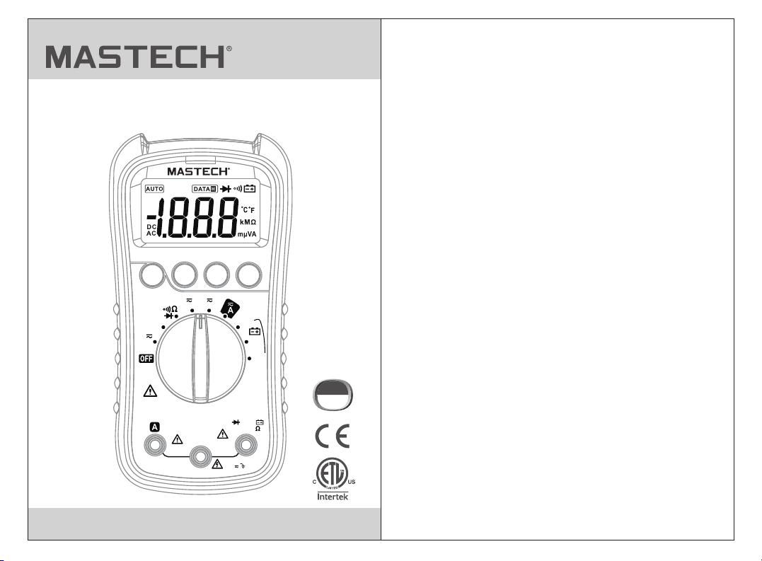
MS8238C
Digital Multimeter
User's Manual
MS8238C
FUNC
TEMP
V
600V
CAT III
MAX 30 sec.
every 15 min.
DIGITAL MULTIMETER
HOLD
mA
μA
COM
10A
MAX
FUSED
RAN NCV
12V
Autorange
Auto power off
TEMP
mAμAV
MAX
200mA
FUSED
MAX
600V
9V
1.5V
CAT III
600V
Page 2

CONTENTS
1.Overview .........................................................1
2. .......................................1Safety Information
2.1 Safety Standards.......................................1
2.2 Precautions..............................................1
2.3 Electrical Symbols .....................................3
3. ..............................4Description and Usage
3.1 Front Panel..............................................4
3.2 Display ..................................................5
3.3 Using the Meter........................................6
3.4 Auto Power Off Function.............................6
4. Operating Instructions..................................7
4.1 AC/DC voltage measurement ......................7
4.2 AC/DC current measurementrent..................7
4.3 Resistance measurement .............................8
4.4 Continuity measurement ...............................9
4.5 Diode test .................................................9
4.6 Battery test...............................................10
4.7 Temperature measurement...........................10
5. Specifications ................................................11
5.1 General Specifications ................................11
5.2 Technical Specifications ..............................12
6. Maintenance....................................................15
6.1 General Maintenance .................................15
6.2 Replacing the Battery and Fuses ...................16
6.3 Replacing the Probe ..................................16
Page 3
1.Overview
WARNING
To avoid electrical shock or personal injury,
please read all safety information,warnings and
precautions before using the meter.
The MS8238C is a small, safe and reliable 3 ½ digit
handheld auto ranging multimeter.This meter can
measure AC/DC voltage, AC/DC current, resistance,
diode, continuity, battery test, temperature and
non-contact voltage tests.This tool is ideal for
professionals and hobbyists alike.
2. Safety Information
2.1 Safety Standards
The MS8238C meets standards for CAT III 600V
installations and a pollution degree of 2.
• The protection provided by the meter can only be
ensured if all safety procedures are strictly followed.
• The safety symbols on the meter are to advise of
potential dangerous situations.Caution is required when
measuring close to the meter’s safety limits.
• Never exceed the protection limit values indicated in
the specifications for each range of measurement.
The special attention should be paid when using the meter
because the improper usage may cause electric shock and
damage the meter .The safety measures in common safety
regulations and operating instruction should be complied
with when using. In order to make fully use of its functions
and ensure safe operations please comply with the usage
in this section carefully.
WARNING
2.2 Precautions
• To avoid electrical shock or personal injury, observe and
follow all safety precautions
• Check the meter for damage before use.Do not use if
any damage is observed.
• Check the test leads for cracks or exposed wires before
using the meter.Replace if necessary.
• Ensure the meter works properly by testing a known
voltage source first. If not working properly, the
protective equipment may be damaged; have the meter
serviced before using.
• Never measure voltages that may exceed the protection
limit indicated on the meter.
• Always be careful when working with voltages above
60V DC or 30V AC rms. Keep fingers behind the probe
barriers when making voltage measurements.
• Make sure the test leads are in the correct input jacks
before measurement.
• Do not expose the meter to explosive gas, dust or vapor.
• When connecting the test leads to a measurement
circuit, connect the common lead first, then the live lead.
Reverse when disconnecting.
• Turn off power to circuit and discharge all capacitors
before making resistance, continuity or diode
measurements.
• In order to avoid incorrect DC voltage readings, check
the circuit for AC voltage first, then put the meter in the
appropriate DC voltage range.
• Turn off circuit power and check fuses before connect
the leads when measuring current.Turn circuit power
on after making connection.
• Never use the meter unless the back cover is in place
and fastened securely.
01
02
Page 4
• When the low battery indicator“ ”is displayed, replace
the battery.The accuracy of the meter cannot be
guaranteed while the low battery indicator is on.
• Before opening the case, always disconnect test leads
from all energized circuits.
• For continued protection against fire, replace fuse only
with the specified voltage and current ratings listed in
the manual.
• Measure known voltage with the meter to verify that
the meter is working properly. If the meter is working
abnormally, stop using it immediately. A protective
device may be damaged. If there is any doubt, please
have the meter inspected by a qualified technician.
2.3 Electrical Symbols
Important safety information.
High voltage with danger.
Ground.
Double Insulation (Class II safety equipment).
Fuse must be replaced as per the specification herein.
Accord with the related EU laws and regulations
AC (Alternating Current)
DC (Alternating Current)
AC & DC (Both direct and Alternating Current)
Conforms to UL STD. 61010-1, 61010-2-030 and
61010-2-033; Certified to CSA STD. C22.2
NO. 61010-1, 61010-2-030 and IEC STD.61010-2-033
CAT III : MEASUREMENT CATEGORY III
is applicable to test and measuring circuits connected to
the distribution part of the building’s low-voltage MAINS
installation.
3 Description and Usage
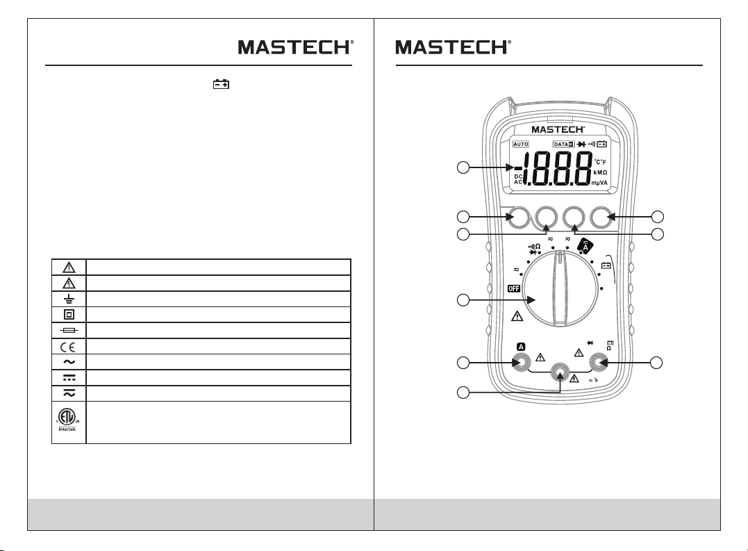
3.1 Front Panel
1
MS8238C
4
5
6
7
9
1.LCD display
2.Non-contact voltage
(NCV) button
3.Range button
4.Function button
5.Data hold button
FUNC
TEMP
V
600V
CAT III
MAX
MAX 30 sec.
every 15 min.
DIGITAL MULTIMETER
HOLD
RAN NCV
mA
μA
12V
9V
1.5V
Autorange
Auto power off
TEMP
mAμAV
COM
MAX
200mA
10A
FUSED
FUSED
MAX
600V
6.Rotary switch
7.A input jack
8.Common jack
9.Input jack
(all functions except current
greater than 200mA)
2
3
8
03
04
Page 5

3.2 Display
4
2
3
1
AUTO
DC
AC
1.AC (alternating current)
2.Polarity indicator
3.DC (direct current)
4.Auto range
5.Data hold
6.Diode measurement
7.Continuity measurement
8.Low battery indicator
9.Reading display
10.Measurement units
DATA
9
6
5
7 8
FUNC button:
•
Press “FUNC” to switch between AC/DC or between
functions.
HOLD button:
3.3 Button Functions
•
Press “HOLD” to keep the current reading on screen.
kMΩ
mµVA
10
“DATA H” symbol will appear on the display.
• Press “HOLD” again to release the hold.
RAN button:
• Press “RAN” to switch to manual range.Each press of
the button will switch to the next highest range, until
reaching the highest range where it will switch to the
lowest range.
• Hold “RAN” to return to auto range.
NCV button:
• Hold the “NCV” button down in any mode and the meter
will activate the non-contact voltage detection.
• Hold the meter up to a voltage source and the buzzer
will sound and the NCV indicator will light up if voltage
is detected.
• Release the “NCV” button to stop NCV detection.
3.4 Auto Power Off Function
After 15 minutes of non-use the meter will automatically
•
turn itself off.
• To turn the meter back on, press any button or turn the
rotary switch to any position.
• To deactivate the auto power off function, hold down
“HOLD” when turning on the meter.
05
06
Page 6

4. Operating Instructions
4.1 AC/DC voltage measurement
Set the rotary switch to the AC/DC voltage position.
•
• Press “FUNC” to switch between AC and DC voltage.
• Connect the red test lead to the input jack and the black
lead to the COM jack.
• Connect the leads to the circuit under test and read the
measurement on the display.Observe polarity for DC
measurements.If “OL” is display, it means the
measurement has exceeded the current range.Move the
rotary switch to a higher range.
WARNING
Do not measure voltages higher than 600V DC or
ACrms to prevent damage to the meter or personal
injury
4.2 AC/DC current measurementrent
• AC/DC current measurement
• Turn off power to the circuit. Allow all capacitors to
discharge.
• Set the rotary switch to the appropriate AC/DC current
range.
• Press “FUNC” to switch between AC and DC current.
• Depending on the current to be measured, connect the
red test lead to either the input or 10A jack and the black
lead to the COM jack.
• Break the circuit and connect the leads in series with
the circuit (black lead on the lower voltage side).
• Turn circuit power on and read the measurement on
the display.If “OL” is display, it means the measurement
has exceeded the current range.Move the rotary switch
to a higher range.
WARNING
Never measure open-circuit voltages exceeding
600V between the input terminals and ground to
prevent injury or damage to the meter
Check fuses before making current measurements.
Make sure to use correct input jicks to prevent
damage to the meter.
4.3 Resistance measurement
Turn off power to the circuit. Allow all capacitors to
•
discharge.
• Set the rotary switch to the multi-function position. The
default function is resistance.
• Connect the red test lead to the input jack and the black
lead to the COM jack.
• Connect the leads to the circuit under test and read the
measurement on the display.
Tips for measuring resistance:
In-circuit resistance is usually different from a resistors
•
rating due to the fact that the meter’s test current flows
in parallel with the circuit.
• For increased accuracy when measuring low resistances,
short the test leads, record the value displayed, then
connect the leads to the circuit and subtract the shorted
value from the circuit measurement.
• When the leads are disconnected from the circuit under
test, “OL” will be displayed on the screen.
To prevent injury or damage to the meter ,turn off
power to circuit and discharge all capacitors fully
before making resistance measurements.
WARNING
WARNING
07
08
Page 7

4.4 Continuity measurement
Turn off power to the circuit. Allow all capacitors to
•
discharge.
• Set the rotary switch to the multi-function position.
Press “FUNC” twice to enter continuity mode.
• Connect the red test lead to the input jack and the black
lead to the COM jack.
• Connect the leads to the circuit under test.If the
measured resistance is less than 30Ω, the buzzer will
sound.
WARNING
To prevent injury or damage to the meter,turn off
power to circuit and discharge all capacitors fully
before making continuity measurements.
4.5 Diode test
• Turn off power to the circuit. Allow all capacitors to
discharge.
• Set the rotary switch to the multi-function position.
Press “FUNC” once to enter diode mode.
• Connect the red test lead to the input jack and the black
lead to the COM jack.
• Connect the red test lead to the anode (+) and the black
lead to the cathode (-) of the diode and read the
measurement on the display. The meter will display
“OL” if the connection is reversed.
WARNING
To prevent injury or damage to the meter,turn off
power to circuit and discharge all capacitors fully
before making diode measurements.
4.6 Battery test
Set the rotary switch to the appropriate battery test range.
•
• Connect the red test lead to the input jack and the black
lead to the COM jack.
• Connect the red test lead to the positive (+) end and the
black lead to the negative (-) end of the battery and read
the measurement on the display.
To prevent injury or damage to the meter,do not
connect the meter to a battery with a voltage rating
exceeding 60V AC or 30V DC
4.7 Temperature measurement
Set the rotary switch to the temperature position.
•
Press “FUNC” to switch between Celsius and Fahrenheit.
• Connect the positive end of the K-type thermocouple to
the input jack and the negative end to the COM jack.
• Place the tip of the thermocouple to the surface of the
object to be tested and read the measurement on the
display.
To avoid injury or damage to the meter,do not move
the rotary switch to the temperture position while
measuring voltages exceeding 30V
WARNING
WARNING
09
10
Page 8

5. Specifications
5.1 General Specifications
Function
Safety Rating
Operating Altitude
Operating Temperature/
Humidity
Storage Temperature/
Humidity
Temperature
coefficient
Max. Input between
terminals and earth
ground
Fuse Protection
Sample Rate Approx. 3 times/sec.
Display
Overload Indication
Low Battery Indication
Polarity Indication
Power Supply
Size(LxWxH)
weight
Range
CAT III 600V, pollution degree: II
<2000m
0~40°C, <80% RH
-10~60°C, <70% RH, remove battery
0.1xaccuracy/°C (>18°C or <28°C)
600V DC or AC rms
µA/mA ranges: FF 400mA H 600V
10A range: FF 10A H 600V
3 ½ digit LCD display
Display shows “OL”
When battery voltage drops below
normal operating voltage,“ ”is
shown on the display
Display automatically displays “-“
DC 9V, NEDA 1604 or 6F22
148x73.5x50mm
about 232g
5.2 Technical Specifications
Accuracy: ±(% of reading + digits) at 18°C~28°C with a
relative humidity of <80%; guaranteed for a period of
one year.
5.2.1 DC Voltage
Measuring range
200mV
2V
20V
200V
600V
Resolution
0.1mV
0.001V
0.01V
0.1V
1V
±(0.5% of reading +3 digits)
±(0.8% of reading +3 digits)
Accuracy
Input impedance: 10MΩ
Max. input voltage: 600V DC or AC rms.
5.2.2 AC Voltage
Measuring range
2V
20V
200V
600V
Resolution
0.001V
0.01V
0.1V
1V
±(0.5% of reading +5 digits)
±(1.0% of reading +5 digits)
Accuracy
Input impedance: 10MΩ
Max. input voltage: 600V DC or AC rms.
Frequency Response: 40~400Hz, sine wave rms
(avg. response)
11
12
Page 9

5.2.3 Resistance
Measuring range
200Ω
2kΩ
20kΩ
200kΩ
2MΩ
Resolution
0.1Ω
0.001kΩ
0.01kΩ
0.1kΩ
0.001MΩ
0.01MΩ20MΩ
±(0.8% of reading +4 digits)
±(1.0% of reading +4 digits)
Accuracy
Overload protection: 600V DC or AC rms
5.2.4 Diode Test
Function
Diode Test
Rang
1.5V
Resolution
1mV
Description
Display shows
forward voltage drop
Overload protection: 600V DC or AC rms
5.2.5 Continuity
Function Description
Overload protection: 600V DC or AC rms
Description
If measured resistance
is less than 30Ω,
buzzer will sound
Open circuit
voltage:~0.5V
5.2.6 DC Current
Measuring range
Resolution
200µA 0.1µA
±(0.8% of reading +3 digits)
±(1.0% of reading +10digits)
20mA
200mA
10A
1µA2000µA
0.01mA
0.1mA
10mA
Overload protection: mA jack: FF 400mA H 600V fuse
10A jack: FF 10A H 600V fuse
Max input current: mA jack: 200mA DC
10A jack: 10A DC
When measuring current exceeding 2A, do not measure
for longer than 2 minutes continuously. Wait 10 minutes
to continue measurement.
Accuracy
5.2.7 AC Current
Measuring range
200µA
2000µA
20mA
200mA
10A
Resolution
0.1µA
1µA
0.01mA
0.1mA
10mA
±(1.0% of reading +3 digits)
±(1.2% of reading +3digits)
±(1.5% of reading +10digits)
Overload protection: mA jack: FF 400mA H 600V fuse
10A jack: FF 10A H 600V fuse
Frequency Response: 40~400Hz, sine wave rms
(avg. response)
Max input current: mA jack: 200mA AC rms
10A jack: 10A AC rms
Accuracy
13
14
Page 10

When measuring current exceeding 2A, do not measure
for longer than 2 minutes continuously.Wait 10 minutes
to continue measurement.
5.2.8 Temperature
Position
-20~750°C 1°C
-4~1382°F
Resolution
1°F
±(2.0% of reading +2 digits)
±(2.0% of reading +4 digits)
Overload protection: FF 400mA H 600V fuse
Accuracy
5.2.9 Battery Test
Position
12V
9V
1.5V
Resolution
0.01V
0.01V
0.001V
±(0.8% of reading +7 digits)
±(0.8% of reading +7 digits)
±(3.0% of reading +5 digits)
Overload protection: FF 400mA H 600V fuse
Accuracy
6. Maintenance
6.1 General Maintenance
This section provides basic information on maintaining
the meter, such as replacing fuses and the battery. Only
experienced and authorized personnel should make
repairs to the meter.
To avoid injury or damage to the meter,do not allow
moisture inside the case and remove test leads
before opening battery cover
• Use a damp cloth to regularly clean the outside of the
meter.Do not use abrasives or chemical solvents.Dirty
or damp input jack can adversely affect readings.
WARNING
15
• To clean input jacks, follow the following steps:
1.Turn off the instrument and remove the test leads.
2.Clear any dirt or other particles on the input jacks.
3.Use a cotton ball/swab with a lubricant (i.e. WD-40) to
clean off the contacts of the input jacks.
4.Use a separate cotton ball/swab for each jack to
prevent cross-contamination.
6.2 Replacing the Battery and Fuses
1. Under no rm al cond it ions, it is u nn ecess ar y to replac e th e fuse.
Don't r ep la ce it unt il t he probes a re u nplug ge d and the pow er i s
shut do wn . Take out th e tw o screw s of t he rear cov er t o remov e
the hou si ng .
2. Th e sp ecifica ti on of the f us e is :
F1 F 10A H 600 V, F2 F 400m A H 600 V
The r ep lacemen t sh ould be o f th e sa me spec if icati on .
3. Th e ba ttery for t hi s multi me ter is 9V NED A 160 4 or 6F22 .
The r ep lacemen t sh ould be o f th e sa me spec if icati on .
4. Don't pu t th e instr um ent into us e un til the r ea r cover is sc re wed
after r ep la cing ba tt ery or fu se .
Warning
To avoid electric shock, make sure the probes are disconnected
from the measured circuit before removing the rear cover.
Make sure the rear cover is tightly screwed before using the
instrument.
6.3 Replacing the Probe
If in sul ation on probe is da mag ed, replace it.
Use meet EN 61010-031 standard, rated CAT III 600V, 10A or better probe.
WARNING
16
Page 11

R-00-05-1568
 Loading...