

Page 1

BENCH MODEL MULTIMETER
Contents
Contents......................................................................................................................................................................................... I
Chapter 1..................................................................................................................................................................................... 1
Safety Standards............................................................................................................................................................................. 1
Warning......................................................................................................................................................................................... 1
Warranty......................................................................................................................................................................................... 2
Chapter 2..................................................................................................................................................................................... 3
Introduction and Specifications..................................................................................................................................................... 3
Front Panel..................................................................................................................................................................................... 3
Rear Panel..................................................................................................................................................................................... 7
LCD Display Description............................................................................................................................................................. 9
Function Descriptions..................................................................................................................................................................... 10
Chapter 3 Operation Manual..................................................................................................................................................... 11
Understanding AC Zero Input Behavior of True RMS Meters.................................................................................................... 11
DC/AC(TRMS) Voltage................................................................................................................................................................. 11
DCmV/ACmV............................................................................................................................................................................. 13
Ohm/Continuity/DIODE.................................................................................................................................................................14
Capacitance Measurement............................................................................................................................................................. 15
Logic Frequency/Duty cycle Measurement................................................................................................................................. 16
Clamp Measurement..................................................................................................................................................................... 17
I
Page 2

Temperature measurement............................................................................................................................................................. 19
DCμA / AcμA measurement......................................................................................................................................................... 20
DC mA / AC mA measurement..................................................................................................................................................... 21
DC A / AC A measurement............................................................................................................................................................. 22
Linear Frequency Measurement..................................................................................................................................................... 23
Relative Measurement................................................................................................................................................................. 24
Max/Min Value............................................................................................................................................................................. 25
Data Hold..................................................................................................................................................................................... 25
Low Passed Filter......................................................................................................................................................................... 25
Peak Value..................................................................................................................................................................................... 26
RS232 Interface............................................................................................................................................................................. 26
Auto Power Off............................................................................................................................................................................. 26
Chapter 4 Specification................................................................................................................................................................. 27
General Specification..................................................................................................................................................................... 27
Range and Accuracy..................................................................................................................................................................... 27
Chapter 5 Maintenance................................................................................................................................................................. 33
Introduction.....................................................................................................................................................................................33
Replacing the Fuse......................................................................................................................................................................... 33
Replacing the Power Fuse............................................................................................................................................................. 34
Replacing the Battery..................................................................................................................................................................... 34
Chapter 6 Accessories................................................................................................................................................................. 35
II
Page 3

BENCH MODEL MULTIMETER
III
Page 4

BENCH MODEL MULTIMETER
Chapter 1
Safety Standards
This style of digital multimeter is designed and manufactured according to the safety requirements set out by the IEC 61010-
1 standards for electronic test instruments . Its design and manufacture is strictly based on the provisions in the 1000V CAT II
of IEC61010-1 and the Stipulation of 2-Pollution Grade.
Warning
To avoid possible electric shock, personal injury, or death, read the following before using the Meter:
Use the Meter only as specified in this manual, or the protection provided by the Meter might be impaired.
Do not use the Meter in wet environments.
Inspect the Meter before using it. Do not use the Meter if it appears damaged.
Inspect the test leads before use. Do not use them if insulation is damaged or metal is exposed. Check the test leads for
continuity. Replace damaged test leads before using the Meter.
Verify the Meter's operation by measuring a known voltage before and after using it. Do not use the Meter if it operates
abnormally. Protection may be impaired. If in doubt, have the Meter serviced.
Whenever it is likely that safety protection has been impaired, make the Meter inoperative and secure it against any
unintended operation.
Have the Meter serviced only by qualified service personnel.
Do not apply more than the rated voltage, as marked on the Meter, between the terminal or between any terminal and
earth ground.
1
Page 5

Replacing the Power Fuse
Always use the power cord and connector appropriate for the voltage and outlet of the country or location in which you
are working.
Remove test leads from the Meter before opening the case.
Never remove the cover or open the case of the Meter without first removing it from the main power source.
Never operate the Meter with the cover removed or the case open.
Use only the replacement fuses specified by the manual.
Use the proper terminal, function and range for your measurements.
Do not operate the Meter around explosive gas, vapor or dust.
When using probes, keep your fingers behind the finger guards.
When making electrical connections, connect the common test lead before connecting the live test lead. When
disconnecting, disconnect the live test lead before disconnecting the common test lead.
Disconnect circuit power and discharge all high voltage capacitors before testing resistance, continuity, diodes, or
capacitance.
Before measuring current, check the Meter's fuses and turn OFF power to the circuit before connecting the Meter to the
circuit.
When servicing the Meter, use only specified replacement parts.
Warranty
The meter is warranted to be free from defects in material and workmanship under normal use and service. The warranty
period is one year and begins on the date of shipment. Parts, product repairs, and services are warranted for 18 months except
for misused, altered, neglected, contaminated, or damaged by accident or abnormal conditions of operation or handling.This
2
Page 6

BENCH MODEL MULTIMETER
warranty does not apply to fuses, disposable batteries.
Chapter 2
Introduction and Specifications
22000 Counts
ACV and DCV up to 1000V
10μV Sensitivity for Voltage measurement.
Linear Frequency 、Logic Frequency and Duty Measurement
Capacity Range from 0.01nF to 220mF
AC TRMS.
Peak Max/Min value Measurement Function
Max/Min,Relative Measurement Function
Low Passed Filter Function
RS-232 Optical Isolation Interface
PC Software for Display Data Record and Data Analysis
Power Supply Methods: 220V/110V AC(50~60Hz)、9V 6F22 Battery、1.5×6 AA Battery
Temperature Measurement
Clamp Measurement
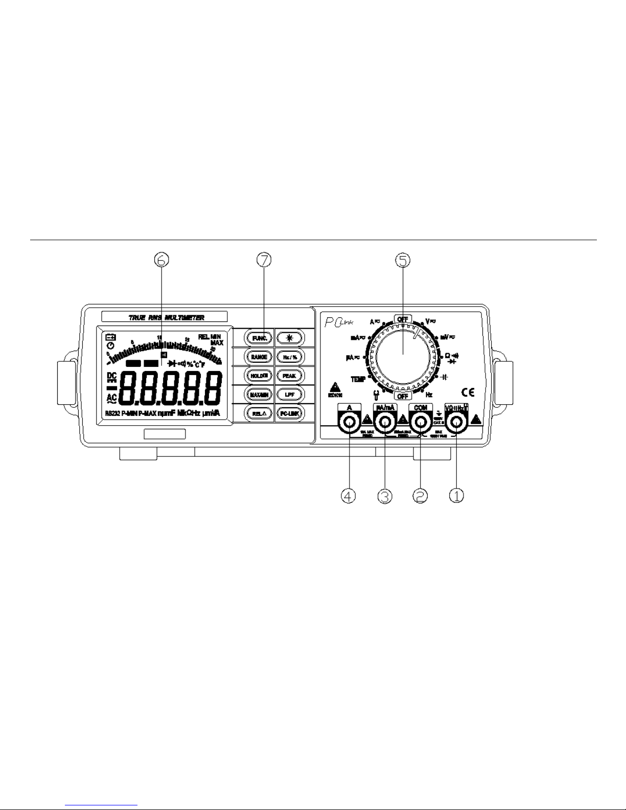
Front Panel
Front panel as below:
3
Page 7
Replacing the Power Fuse
Front Panel Features
1. VΩHz Terminal
Input positive terminal for all measurement except current measurement , connected with red test leads.
2. COM Terminal
4
Page 8

BENCH MODEL MULTIMETER
Input common terminal for all measurement , connected with black test leads.
3. μA/mA Terminal
Input positive terminal for current measurement (μA/mA) , connected with red test lead.
4. A Terminal
Input positive terminal for current measurement (A) , connected with red test lead.
5. Rotary Switch
Switching positions correspondingly when changing different input signals.
Note: Switching position before changing signals in case caused damage.
6. Display Screen
7. Button
Button Description
Name Description
FUNC Function toggling
Back Light(Wake up), press this button can wake the meter in auto power off mode
RANGE Toggle to manual mode in autorange mode , increase range in manual mode;toggle to autorange mode
when pressing longer than 1 S in manual mode.
Hz Under frequency measurement, toggle from frequency to duty.
HOLD Select hold function.,when the measuing value overload ,Display ‘OL’;
PEAK Select peak function: The peak values are stored in external Capacitors.
MAX/MIN Select max/min function: The meter displays the maximum or minimum value.
5
Page 9
Replacing the Power Fuse
Name Description
LPF To activate the low passed filter function, most of noise above 1KHz will decay greatly.
RELΔ LCD panel displays relative value.
PC-LINK LCD panel displays ‘RS232’ , the meter communicates with PC software.
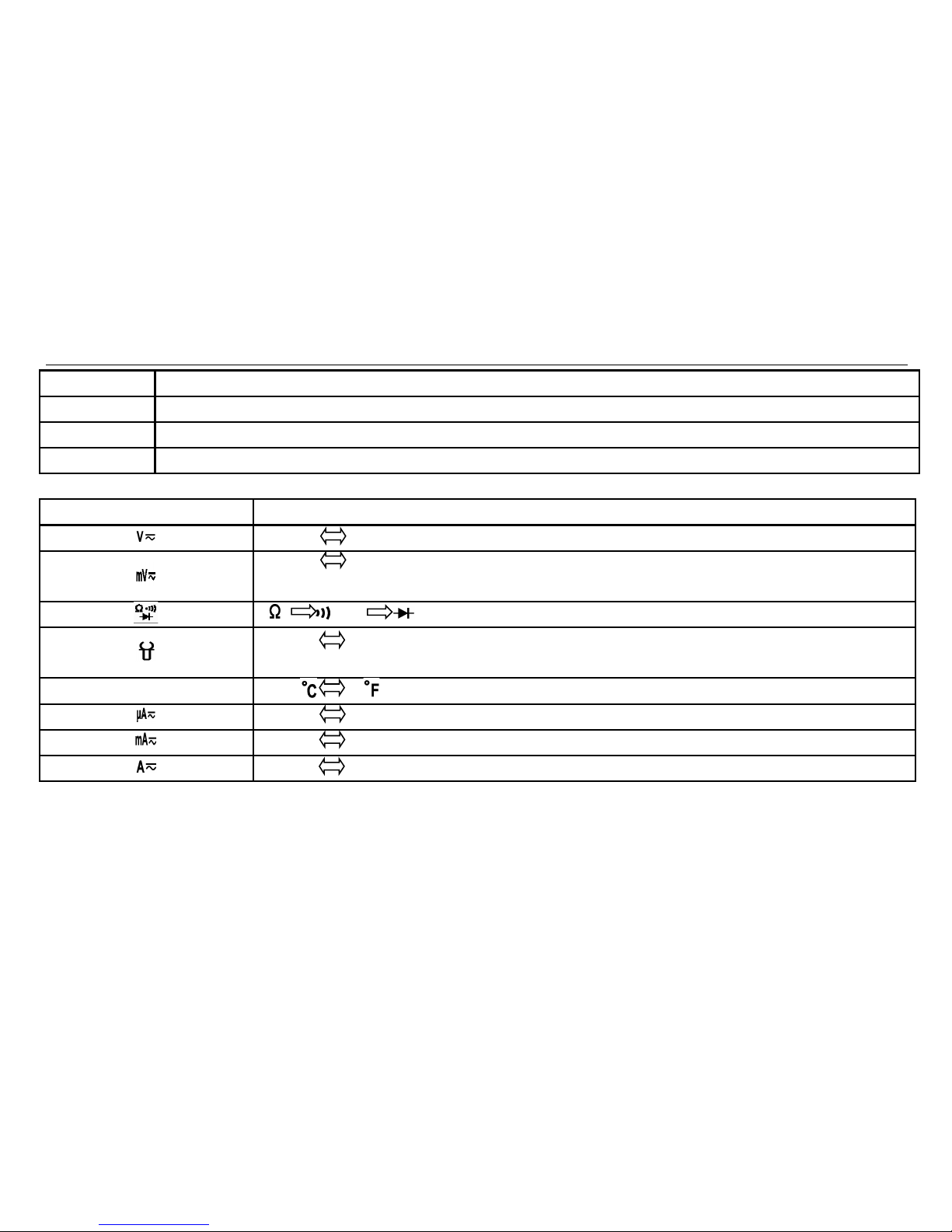
FUNC button description
Rotary Position Input Signal
DCV
ACV
DCmV ACmV
DCA ACA
TEMP
DCμA ACμA
DCmA ACmA
DCA ACA
6
Page 10
BENCH MODEL MULTIMETER
Button description
RANGE HOLD MAX/MI
N
REL Hz PEAK
(
Note
2
)
LPF PCLINK(N
ote 1)
Voltage ○ ○ ○ ○ ○ ○ ○ ○ ○
Current ○ ○ ○ ○ ○ ○ ○ ○
Clamp ○ ○ ○ ○(A
C
)
○ ○ ○ ○
Resistance ○ ○ ○ ○ ○ X ○
Capacitance ○ ○ ○ ○ ○ X ○
Frequency X ○ X X ○ ○ ○
Duty X ○ X X ○ X ○
Temperature X ○ ○ ○ ○ X ○
Note 1: In Capacitance Measureing mode ,when MAX/MIN or REL function is activated,the data sent to PC software is the
actual value.
Note 2: When PEAK function is activated, the data sent to PC software is invalid
Note 3: ○ meaning the function can be selected, X menaing the function is invalid
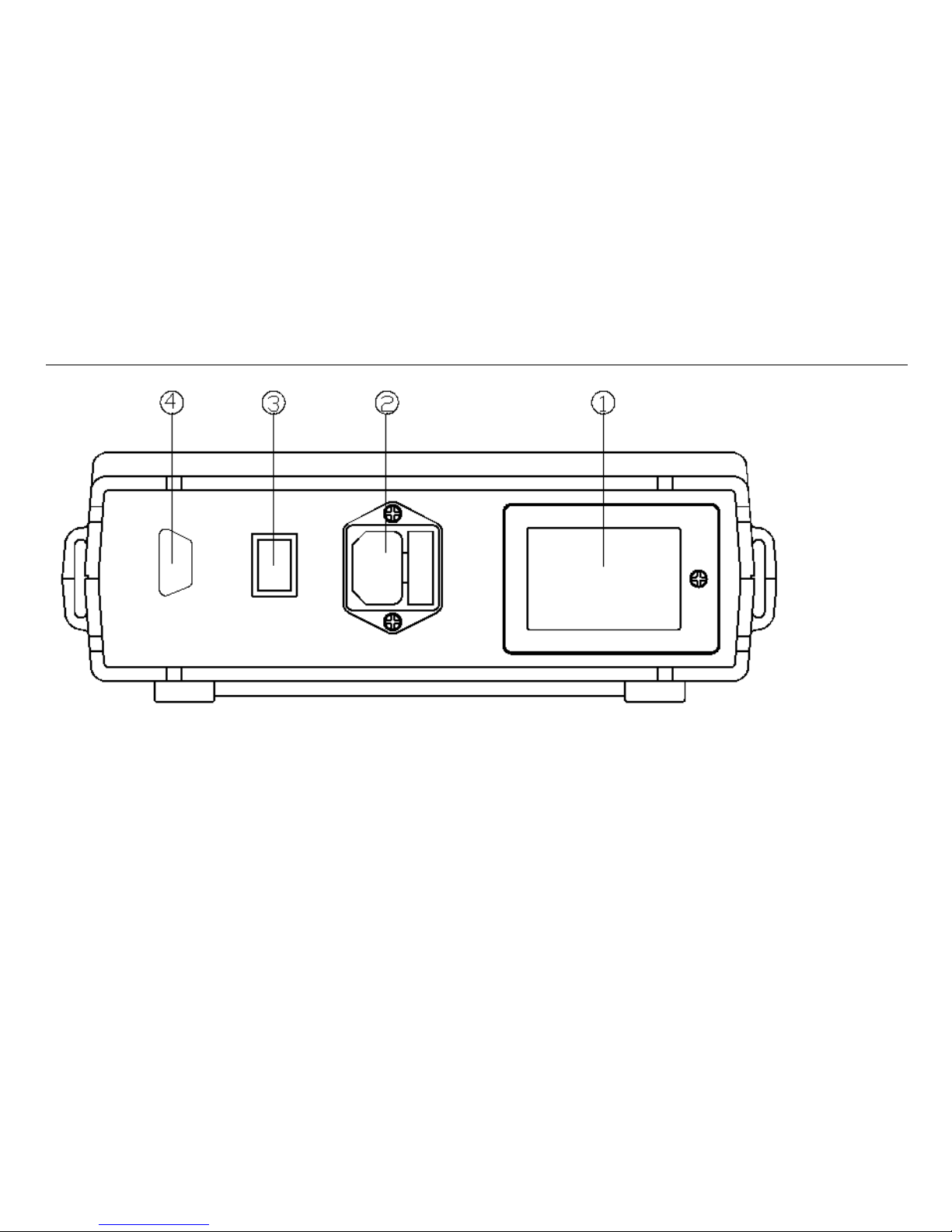
Rear Panel
Rear panel as blow
:
7
Page 11
Replacing the Power Fuse
(1) Battery Cover
Replace 9V 6F22 or 1.5×6 AA battery.
(2) Supply Power Inlet with Fuse, Houses Fuse 0.1A/250V.
(3) Power Switch
(4) RS232 Socket
8
Page 12
BENCH MODEL MULTIMETER
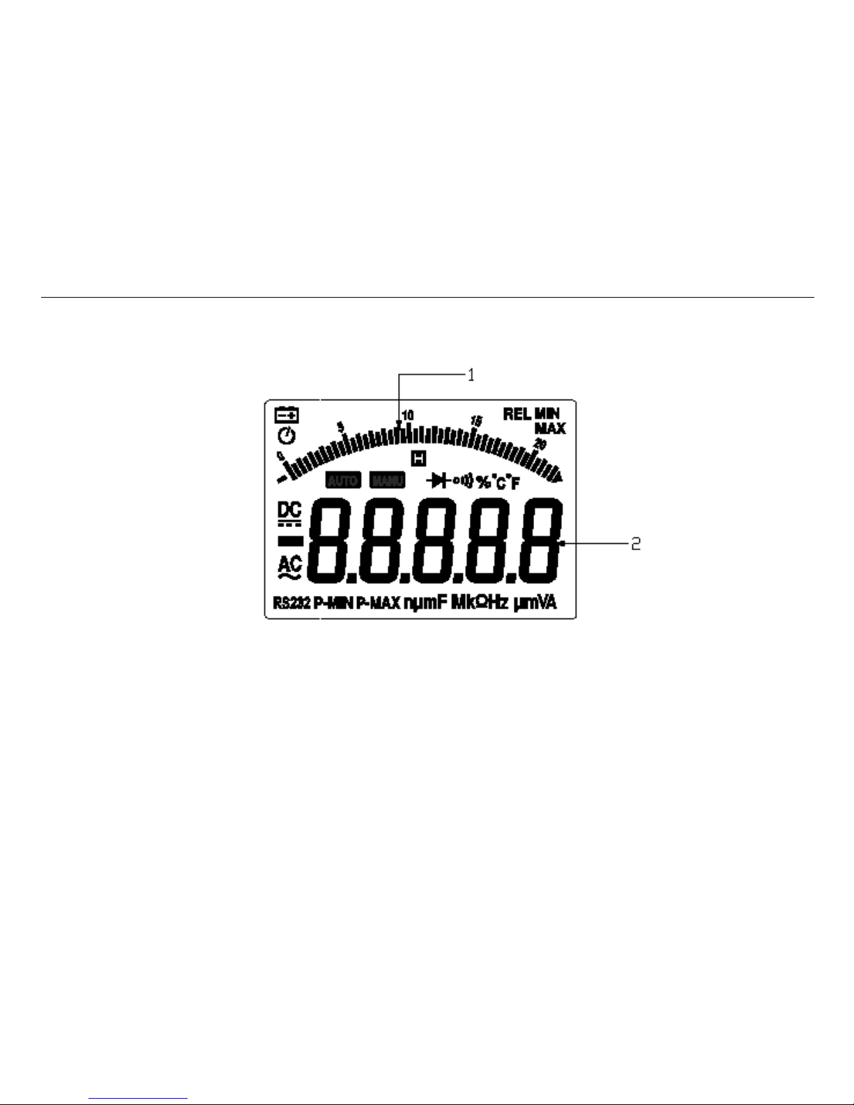
LCD Display Description
(1)
Bargraph Display Zone
(2)
Digital Display Zone
9
Page 13

Replacing the Power Fuse
Display Annunciators and Indicators
Sign Description
Battery (low battery when shown on display.)
Auto power off function is selected
DC (Direct Current)
AC (Alternating Current)
Hold status is selected
Diode test is selected
Continuity test is selected
RS232
Communication with PC terminal is selected
P-MIN
Reading is minimum peak value
P-MAX
Reading is maximum peak value
REL
Relative readings function is selected
MIN
Reading is minimum value
MAX
Reading is maximum value
10
Page 14

BENCH MODEL MULTIMETER
Function Descriptions
Auto range or manual range:Toggle to manual mode in autorange mode , increase range in manual mode;toggle to
autorange mode when pressing longer than 1 S in manual mode.
Linear frequency
:
When input signal is AC voltage or current, press ‘Hz’ button to activate frequency measurement.
Logic frequency and duty : In frequency mode, press ‘Hz’ button switches the mode to/from duty cycle mode.
Continuity and diode test:Under continuity test , the beeper emits a continuous tone if the input is approximately
below 30Ω.Under diode test,the forward voltage of the semiconductor junction (or junctions) is measured.
Relative measurement: Show the difference between actual value and the relative base.
Display Value = Actual Value — Relative Value.
Max/Min:Show the minimum or maximum value recorded and the present measurement.
Low passed filter:Most of noise above 1KHz will decay greatly. So obtain more stable and accurate readings on low
frequency response.
Peak hold: Hold Max and Min peak value.
RS232 Interface.
Chapter 3 Operation Manual
Understanding AC Zero Input Behavior of True RMS Meters
True RMS Meters accurately measure distorted waveforms, but when the input leads are shorted together in the AC
function the Meter displays a residual reading between 0 and 30 counts, When the test leads are open, the display reading may
fluctuate due to interference, These offset reading are normal .they do not affect the meter ’s measurement accuracy over the
11
Page 15

Replacing the Power Fuse
specified measurement range.
DC/AC(TRMS) Voltage
The Meter is capable of measuring voltage up to 1000 V DC and 750 V AC.
To perform a voltage measurement:
1. Turn rotary switch to position,LCD panel displays‘DC’; press FUNC button when measuring AC voltage,
and LCD display ‘AC’;
2. Connect red test lead with VΩHz terminal and black test lead with COM terminal;
3. Connect test leads to test circuit;
4. The Meter selects the appropriate range in the autorange mode. The function and measurement are displayed;
5. By pressing the RANGE button, it is possible to select range manually. While displaying OL during manual range
measurement, it is necessary to select a larger range. When OL displaying under the maximum range, it indicates
the voltage exceeding 1000V,so it is necessary to remove both the red and black test leads from the measured
circuit immediately.
Note: In case of probe hanging in the air, the voltage inducted by the testing line may cause unstable readings on the
display screen, but that will not affect the accuracy of measurement.
12
Page 16

BENCH MODEL MULTIMETER
DCmV/ACmV
The Meter is capable of measuring mV up to 220mV.
To perform a mV measurement:
1. Turn rotary switch to position,LCD panel displays‘DC’; press FUNC button when measuring AC mV,
and LCD display ‘AC’;
2. Connect red test lead with VΩHz terminal and black test lead with COM terminal;
3. Connect test leads to test circuit;
4. The function and measurement are displayed;
5. While displaying OL during measurement, it is necessary to remove both the red and black test leads from the
13
Page 17

Replacing the Power Fuse
measured circuit immediately.
Notes: In case of probe hanging in the air, the voltage inducted by the testing line may cause unstable readings on the
display screen, but that will not affect the accuracy of measurement.
Note: Do not measuring the voltage exceed the 220mV voltage.
14
Page 18

BENCH MODEL MULTIMETER
Ohm/Continuity/DIODE
The Meter is capable of measuring Ohm up to 220MΩ.
To perform a measurement:
1. Turn rotary switch to Ωposition,LCD panel displays‘Ω’; press FUNC button to select continuity function or
diode function;
2. Connect red test lead with VΩHz terminal and black test lead with COM terminal;
3. Press FUNC button selecting a function of the ohm、continuity or diode
。
4. Connect test leads to test circuit;
5. The function and measurement are displayed;
6. The beeper emits a continuous tone if the input is approximately below 30Ω.Under diode test,The forward voltage
of the semiconductor junction is measured.
Note: In case of performing resistance or continuity test on circuit board, it is necessary firstly to turn off the power of
the circuit board and then perform the measurement. As there may be other parallel circuits, so the displayed
value of test is not surely the actual value of the resistance.
15
Page 19

Replacing the Power Fuse
Capacitance Measurement
The Meter is capable of measuring up to 220mF
To perform a capacitance measurement:
1. Turn rotary switch to position,LCD panel display‘F’;
2. Connect red test lead with VΩHz terminal and black test lead with COM terminal;
3. Connect test leads to measure capacitance;
4. The function and measurement are displayed
Notes: 1). Discharge the capacitance before
measuring.
2). Do not to perform capacitance measurement on a
circuit board on which there are other parallel
devices, for that may cause a very large error.
16
Page 20

BENCH MODEL MULTIMETER
Logic Frequency/Duty cycle Measurement
The measurement frequency up to 220MHz(Vpp 3V),duty cycle range is of 10%~90%
To perform the measurement:
1. Turn rotary switch to Hz position,LCD panel displays‘Hz’;
2. Connect red test lead with VΩHz terminal and black test lead with COM terminal;
3. Connect test leads to measuring circuit;
4. Pressing Hz button to toggle between
frequency and duty cycle measurement;
5. The function and measurement are displayed.
17
Page 21

Replacing the Power Fuse
Clamp Measurement
The Meter is capable of measuring current up to 2200A
To perform the measurement:
1. Turn rotary switch to position,LCD panel displays‘DC’; press FUNC button when measuring AC Current,
and LCD display ‘AC’;
2. Connect red test lead with VΩHz terminal and black test lead with COM terminal;
3. Connect test leads to clamp adapter’s output terminal ;
4. The Meter selects the appropriate range in the autorange mode. The function and measurement are displayed;
5. By pressing the RANGE button it is possible to select range manually. While displaying OL during manual range
measurement, it is necessary to select a larger range. When OL displaying under the maximum range, it indicates
the voltage exceeding 2200A,so it is necessary to remove both the red and black test leads from the adapter output
18
Page 22

BENCH MODEL MULTIMETER
terminal immediately.
Note: It is required clamp adapter output 1mV/A
Temperature measurement
The Meter is capable of measuring temperature from -30℃ to 1300℃
To perform the measurement:
1. Turn rotary switch to TEMP position,LCD panel default displays ambient temperature;
2. Connect Multi-Function socket IN terminal with VΩHz terminal ;Connect Multi-Function socket COM terminal
with COM terminal;
3. Connect K type thermocouple to Multi-Function socket input terminal;
Clamp adapter
19
Page 23

Replacing the Power Fuse
4. The function and measurement are displayed, it will display ‘OL’ if the measuring temperature is higher than
1300℃ or lower than -30℃.
DCμA / AcμA measurement
The Meter is capable of measuring current from 0.01μA~2200μA
To perform the measurement:
1. Turn rotary switch to position,LCD panel displays‘DC’; press FUNC button when measuring AC
Current, and LCD display ‘AC’;
2. Connect red test lead with μA/m A terminal and black test lead with COM terminal;
3. Turn off the power of the measured circuit, connect the red and black probes to the measured circuit in serial way
and then turn on the power of the measured circuit;
20
Page 24

BENCH MODEL MULTIMETER
4. The Meter selects the appropriate range in the autorange mode. The function and measurement are displayed;
5. By pressing the RANGE button it is possible to select range manually. While displaying OL during manual range
measurement, it is necessary to select a larger range. When OL displaying under the maximum range, it indicates
the voltage exceeding 2200μA ,so it is necessary to remove both the red and black test leads from the circuit
immediately.
21
Page 25

Replacing the Power Fuse
DC mA / AC mA measurement
The Meter is capable of measuring current from 1μA~220mA
To perform the measurement:
1. Turn rotary switch to position,LCD panel displays‘DC’; press FUNC button when measuring AC
Current, and LCD display ‘AC’;
2. Connect red test lead with μA/m A terminal and black test lead with COM terminal;
3. Turn off the power of the measured circuit, connect the red and black probes to the measured circuit in serial way
and then turn on the power of the measured circuit;
4. The Meter selects the appropriate range in the autorange mode. The function and measurement are displayed;
22
Page 26

BENCH MODEL MULTIMETER
5. By pressing the RANGE button it is possible to select range manually. While displaying OL during manual range
measurement, it is necessary to select a larger range. When OL displaying under the maximum range, it indicates
the voltage exceeding 220mA,so it is necessary to remove both the red and black test leads from the circuit
immediately.
DC A / AC A measurement
The Meter is capable of measuring current from 0.1mA~10A
To perform the measurement:
1. Turn rotary switch to position,LCD panel displays‘DC’; press FUNC button when measuring AC
Current, and LCD display ‘AC’;
2. Connect red test lead with A terminal and black test lead with COM terminal;
3. Turn off the power of the measured circuit, connect the red and black probes to the measured circuit in serial way
and then turn on the power of the measured circuit;
4. The function and measurement are displayed.
23
Page 27

Replacing the Power Fuse
Note : Make sure the measurement current not exceed 10A to avoid damage of the meter.
Linear Frequency Measurement
To perform the measurement:
1. When performing voltage or current measurement, in case of measured value being AC or including AC elements,
it is possible to measure and display the frequency on the display zone, by pressing Hz key. However it has a
certain requirements for the amplitude of alternating signal and the meter has varied requirements for signal
amplitude when it is in different ranges, for information of which please refer to below;
2. Press Hz key again to measure duty.
24
Page 28

BENCH MODEL MULTIMETER
Relative Measurement
Except for frequency, duty , Clamp(AC) , all other measurements can employ relative measurement. Press RELΔ key to
enter relative measurement and the meter will record the initial value when pressing the key.
Displayed value = Actual value — Initial value
Press RELΔagain to exit relative measurement. Changes of measurement value may be found in relative measurement which
also can be used for the small resistance measurements, for example, when performing resistance measurement, connect the
red test lead and the black test lead in short, press the REL△ key to record the values of resistance (resistance of both the red
and black lines), and after that performing resistance measurement again the lead resistance will have been taken off from the
display value.
25
Page 29

Replacing the Power Fuse
Notes: Duty to subtraction, the relative value is sometimes a negative one.
Max/Min Value
The meter displays the maximum or minimum value of the input in Max/Min mode.When Max/Min is pressed for the first
time, the meter displays the maximum value.When Max/Min is pressed again, the meter displays the minimum value. When
Max/Min is pressed for the third time, the meter displays max value. The meter returns to normal operation if Max/Min is
pressed and held for longer than one second.
Data Hold
Pressing HOLD button to activate hold mode,LCD panel display ‘HOLD’, hold mode makes the meter stop updating the LCD
,pressing HOLD button again, will exit hold mode.
Low Passed Filter
The meter provides a 3-order low-pass filter to reduce the influence of high frequency noise above 1KHz (3dB). This LPF
feature is available in all ACV measuring mode. Pressing LPF button to activate LPF function, in LPF mode , the ‘AC’ sign
on LCD panel will blink until the LPF mode is canceled. When LPF mode is activated, most of noise above 1KHz will decay
greatly. So we can obtain more stable and accurate readings on low frequency response.
;
pressing LPF button again exit
LPF mode.
26
Page 30

BENCH MODEL MULTIMETER
Peak Value
The peak values are stored in external capacitors. The precision of Peak mode measurement can be enhanced by calibration.
Calibration for Peak mode is invoked by pressing Peak button for more than 2 seconds. Entering Peak mode will automatically
execute peak calibration. Pressing peak button,the meter display max peak value. Press Peak button again ,the meter display
min peak value,press peak button longer than 1S ,the meter exits peak mode.
RS232 Interface
Connecting RS232 terminal and PC USB socket with RS232 cable in accessories, and press PCLINK Button
,
then the
meter communicate with PC software , LCD display “RS232”. PC can record , print the data from the meter by running PC
software correspondingly. Press PCLINK button again, the meter terminate the communication with PC and don’t display
‘RS232’.
Auto Power Off
The meter has a default auto power off function. If the meter is idle for more than 15 minutes, the meter automatically turns the
power off ; after power off, press button to wake up the meter.
27
Page 31

Replacing the Power Fuse
Chapter 4 Specification
General Specification
22000 counts,autorange / manual range, measurement rates of 2, 20 timers/second(slow, fast).
The max overload protective voltage is up to AC 250 V (TRMS)except for current and voltage.
In μA/mA mode, protective current is 0.3A; In A mode, protective current is 10A.
Overload Indicator: OL.
Fuse : 0.3A/250V(μA/mA terminal), 10A/250V(A terminal), 0.1A/250V(line power fuse)
Optical Isolution RS232C Interface.
Operating Temperature: 18℃~28℃(relative humidity <=80%)
Storage Temperature: -20℃~60℃(relative humidity <=80%)
Temperature Coefficient: 0.05×Specified Accuracy per ℃ (<18℃ or >28℃)
Dimensions: 238mm(W)×230mm(L)×83mm(H)
Weight : Approx. 1.5kg, without power cord
Range and Accuracy
The below-listed accuracies under different ranges refer to those which are guaranteed by the meter within one-year
calibration, under the operating temperature of 18℃-28℃ and relative humidity less than 80%.The presentation for accuracy
is: ± (a% reading digits + b digits)
28
Page 32

BENCH MODEL MULTIMETER
AC Voltage Accuracy
Range Resoluti
on
Accuracy
40Hz~60Hz 60Hz—5KHz 5KHz—10KHz
200mV 0.01mV ±(0.5% +30) ±(1.5% +30) ±(2.5% +30)
2V 0.1mV ±(0.5% +30) ±(1.5% +30) ±(2.5% +30)
20V 1mV ±(0.5% +30) ±(1.5% +30) ±(2.5% +30)
200V 10mV ±(0.5% +30) ±(1.5% +30) ±(2.5% +30)
750V 0.1V ±(0.5% +30) ±(1.5% +30)
(
1KHz
)
Unspecified
Note: Above accuracies can be guaranteed within 20% - 100% of the full range .
DC Voltage Accuracy
Range Resolution Accuracy
200mV 0.01mV ±(0.05% +6)
2V 0.1mV ±(0.05% +6)
20V 1mV ±(0.05% +6)
200V 10mV ±(0.05% +6)
1000V 0.1V ±(0.05% +6)
Note: Above accuracies can be guaranteed within the full range.
AC Current Accuracy
Range Resolutio Accuracy
29
Page 33

Replacing the Power Fuse
n 40Hz
~
60Hz
60Hz~1KHz 1KHz~5KHz
200μA 0.01μA ±(0.8%
+30)
±(1.0% +30) ±(1.2% +30)
2000μA 0.1μA ±(0.8%
+30)
±(1.0% +30) ±(1.2% +30)
20mA 1μA ±(0.8%
+30)
±(1.0% +30) ±(1.2% +30)
200mA 10μA ±(0.8%
+30)
±(1.0% +30) ±(1.2% +30)
10A 1mA ±(1.0%
+30)
±(1.5% +30) ±(2 % +30)
Note:Above accuracies can be gurranteed within 20
%
- 90
%
of the full range.
DC Current Accuracy
Range Resolution Accuracy
200μA 0.01μA ±(0.15% +15)
2000μA 0.1μA ±(0.15% +15)
20mA 1μA ±(0.15% +15)
200mA 10μA ±(0.15% +15)
30
Page 34

BENCH MODEL MULTIMETER
10A 1mA ±(0.5% +15)
Note: Above accuracies can be guaranteed within the full range.
Resistance Accuracy
Range Accuracy
200Ω ±(0.1% +10)
2KΩ ±(0.1% +10)
20KΩ ±(0.1% +5)
200KΩ ±(0.1% +5)
2MΩ ±(0.1% +10)
20MΩ ±(0.5% +10)
200MΩ ±(2 % +10)
Notes: 1. Above accuracies can be guaranteed within the full range.
2.Accuracy for diode and continuity are unspecified.In Continuity Test Mode,the bluzzer will beeper if the
measure value lower than 20Ω,may or not beep if the measure value between 20Ωand 50 Ω.not beep when the
measure value higher than 50Ω
Capacitance Accuracy
Range Resolution Accuracy
20nF 0.01nF ±(1.2% +30)
200nF 0.1nF ±(1.2% +30)
2μF 1nF ±(1.2% +30)
20μF 10nF ±(1.2% +30)
31
Page 35

Replacing the Power Fuse
Range Resolution Accuracy
200μF 0.1μF ±(2.2% +30)
2000μF 1μF ±(2.2% +30)
20mF 10μF ±(2.2% +30)
200mF 100μF Unspecified
Notes:
Above accuracies for film capacitor or better can be guaranteed within the full range.
Above specification from 20nF to 2uF ranges are specified under REL mode. The reading is calibrated to zero by
relative function when input is floating.
Logic Frequency:
Frequency Range Signal Accuracy
20Hz~220MHz Vpp 3V square wave ±(0.06% +10)
Linear Frequency:
Input Range AC Sensitivity (TRMS sine wave)
5Hz~10KHz 10KHz~100KHz
200mV 5mV 10mV
2V 50mV 100mV
20V 500mV 1000mV
200V 5V 10V
32
Page 36

BENCH MODEL MULTIMETER
Input Range AC Sensitivity (TRMS sine wave)
5Hz~10KHz 10KHz~100KHz
750V 50V(Note 1) Unspecified
200μA 5μA(Note 1) Unspecified
2000μA 50μA(Note1) Unspecified
20mA 50μA(Note 1) Unspecified
200mA 5mA(Note 1) Unspecified
10A 500mA(Note1) Unspecified
Note 1:Freqency response 50Hz~10KHz.
Duty
Duty Scale
Accuracy
5%~95% ±10%
ClAMP
Range Resolution Accuracy
DC 220A 0.01A ±(0.1%+10
)
DC 2200A 0.1A ±(0.1%+10)
AC 220A (50~60Hz) 0.01A ±(1%+30)
AC 2200A(50~60Hz) 0.1A ±(1%+30)
Temperature
Range Resolution Accuracy
33
Page 37

Replacing the Power Fuse
-30℃~1300℃ 1℃ ±(1%+2)
Note: Accuracies apply following 90 minutes settling time after a change in the ambient temperature of the instrument.
Chapter 5 Maintenance
Introduction
Repairs or servicing not covered in this manual should only be performed by qualified personnel.
Replacing the Fuse
Use the following procedure to examine or replace the multimeter of fuses:
Turn the power switch to off, and remove the power cable from live power source.
Disconnect test leads from any live source, turn the rotary switch to off, and remove the test leads from the input
terminals.
34
Page 38

BENCH MODEL MULTIMETER
Open the tools cover on the top cover, and open the fuse cover in the tool case.
Remove the blown fuse, replace with fuse of the same size and rating. Make sure the new fuse is centered in the fuse
holder.
Replace the blown fuse with same ratings. The A input terminal is protected by a F1 0A/250V fast blow ceramic fuse,
Φ6×32mm. The mA input terminal is protected by a F300mA/250V fast blow fuse, Φ5×20mm..
Fuse rarely need replacement and blow almost always as a result of the operator’s error.
Never use the bench multimeter unless the fuse cover is in place and fastened fully.
Note: To avoid electrical shock, disconnect the test leads and any input signals before replacing the fuses. Replace only with
same type of fuses. The A input terminal is protected by a F10A/250V fast blow ceramic fuse. The mA input terminal is
protected by a F300mA/250V fast blow fuse.
Replacing the Power Fuse
Use the following procedure to examine or replace the power fuses:
1. Turn the power switch to off, and remove the power cable from live power source.
2. Disconnect test leads from any live source, turn the rotary switch to off, and remove the test leads from the input terminals.
3. Replace the power fuse from the supply power inlet with fuse. Replace the blown fuse with same ratings.
4. The power fuse: 100mA / 250V, Fast, Φ5×20mm.
Note: To avoid electrical shock, disconnect power cable from live power source , and remove the test leads and any input
signals before replacing the power fuses. Replace only with same type of fuses.
35
Page 39

Replacing the Power Fuse
Replacing the Battery
When the multimeter displays the “ ” mark, the battery must be replaced to maintain proper operation. Use the following
procedure to replace the battery:
Disconnect test leads from any live source, turn the rotary switch to off, and remove the test leads from the input
terminals.
Remove screws on the battery cover and open the case.
Remove the exhausted battery and replace with a new equivalent 9 voltge battery.
Two types of batteries are used in the bench multimeter: one of is a NEDA 1604 6F22 006P type one piece or equivalent 9
voltge battery; other of is IEC LR6 AM3 AA 1.5V×6 pieces.
Never use the bench multimeter unless the battery cover is in place and fastened fully.
Note: To avoid electrical shock, disconnect power leads from live power sourceand remove the test leads and any input
signals before replacing the battery. Replace only with same type of battery.
Chapter 6 Accessories
Item Quantity
Manual 1
Test Leads 2
Power Cord
1
36
Page 40

BENCH MODEL MULTIMETER
RS232C Cable(3415)
1
K Type Thermocouple 1
Multi-Function Socket 1
CD-ROM 1
37
 Loading...