

Page 1
02
MS7222
0301
Intr oduct ion
RTD Cal ibrat or is a han dheld t ool for c alibr ating R TD
(Res istan ce Tempera ture De tecto r) tran smitt ers,
incl uding m ost pul sed tra nsmit ters. I t simul ates an d
meas ures se ven diff erent t ypes of R TDs, in u nits of
°C or °F. It a lso sim ulate s and mea sures r esist ance
in uni ts of ohm s.
If the c alibr ator is d amage d or some thing i s missi ng,
cont act the p lace of p urcha se imme diate ly. Conta ct your
dist ribut or for in forma tion ab out acc essor ies.
04
RTD CALIBRATOR
OPERATING INSTRUCTION
Saf ety Info rmati on
05
To avoid p ossib le elec tric sh ock or pe rsona l injur y:
• Neve r apply m ore tha n 30 V betw een any t wo term inals ,
or bet ween an y termi nal and e arth gr ound.
Make s ure the b atter y door is c losed a nd latc hed
befo re you op erate t he cali brato r.
Remo ve test l eads fr om the ca libra tor bef ore you o pen
the ba ttery d oor.
Do not o perat e the cal ibrat or if it is d amage d.
Do not o perat e the cal ibrat or arou nd expl osive g as,
vapo r, or dust .
•
•
•
•
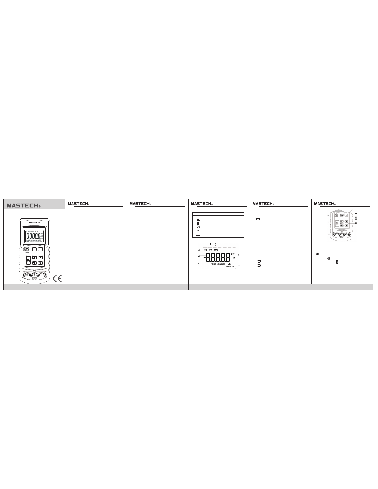
Inte rnati onal Sy mbols
Symbols
Refer to this instruction sheet for information
about this feature.
Meaning
Fuse
Conforms to European Union directives
Double insulated
Battery
Earth ground
Gett ing Acqu ainte d With Th e Calib rator
1. The RT D type an nunci ators s how the s elect ed
RTD typ e.
2. Sho w the mea sured o r simul ated va lue in de grees o r
ohms . When OL ap pears , the val ue is out o f range .
3. It wi ll lit wh en the ba ttery i s low.
4. INP UT will li t when me asuri ng an RTD o r resis tance .
5. OUT PUT will l it when s imula ting an R TD or res istan ce.
6. Whe n an RTD typ e is sele cted, o ne of the se is lit t o
show t he sele cted sc ale.
7. Whe n measu ring an RT D, one of t hese is l it to ind icate
a two- wire, t hree- wire, o r four- wire co nfigu ratio n.
These a nnunc iator s are not u sed whe n simul ating a n
RTD or re sista nce (ou tput) .
8. POW ER ON/O FF
9. Pre ss to sel ect inp ut (mea sure) o r outpu t (simu late)
mode .
10. IN PUT/O UTPUT te rmina ls.
11. Pres s to scro ll up or do wn disp lay. Hol d down to
scro ll fast er.
12. In s imula te mode , press t o step up o r down 10 ° or
10 Ω. In m easur ement m ode, pr ess it to s elect a
two- wire, t hree- wire, o r four- wire RTD i nput
conf igura tion.
13. Pr ess to to ggle te mpera ture sc ales be tween
Cels ius and F ahren heit.
14. Pr ess to se lect a di fferen t RTD typ e. When y ou
sele ct the e ty pe (ohm s), dis playe d units a re ohms ,
not de grees .
°C/°F
RTD
TYPE
Auto P ower Of f funct ion
In the p roces s of meas uring o r simul ating , if ther e is no
any ac tion on t he mete r withi n 30 minu tes, th e meter w ill
be Auto P ower Off . In auto p ower of f statu s to pres s the
key, the m eter wi ll powe r on. The a uto pow er off
func tion wi ll be can celle d such as f ollow ing ope ratio n:
1. Pre ss the ke y to turn o ff the met er, if the m eter
powe r on.
2. Pre ss and ho ld the ke y to turn o n the met er.
3. The au to powe r off fun ction w ill be ca ncell ed.
4. To resum e the aut o power o ff func tion, t urn off t he
mete r and tur n on it aga in, the a uto pow er off fun ction
will b e resum ed.
CO NT EN TS
Intr oduct ion ... ..... ..... ..... ..... ..... ..... ..... ..2
Safe ty Info rmati on .... ...... ..... ..... ...... ..... 2
Inte rnati onal Sy mbols .... ..... ..... ...... ..... ....3
Gett ing Acq uaint ed
With T he Cali brat or .... ..... .... ..... ..... ..... .3
Auto P ower O ff Func tion. ..... ..... .... ..... ..... ...5
Meas uring a n RTD or Re sista nce.. ..... ..... ....6
Simu late an R TD or Resi stanc e.... ..... ...... ....7
Spec ifica tions … ..... ..... ..... ..... ..... ..... ..... ..... 8
Gene ral Spe cifica tions … ..... ..... ...... ..... ..... 10
Main tenanc e ……... ...... ..... ...... ...... ..... ...... ..10
02
MS7222
RTD CALIBRATOR
RTD
TYPE
°C/°F
Page 2
0906 08 1 0 1107
HYS 00668 4
Spec ifica tions
Gene ral Spe cific ation s
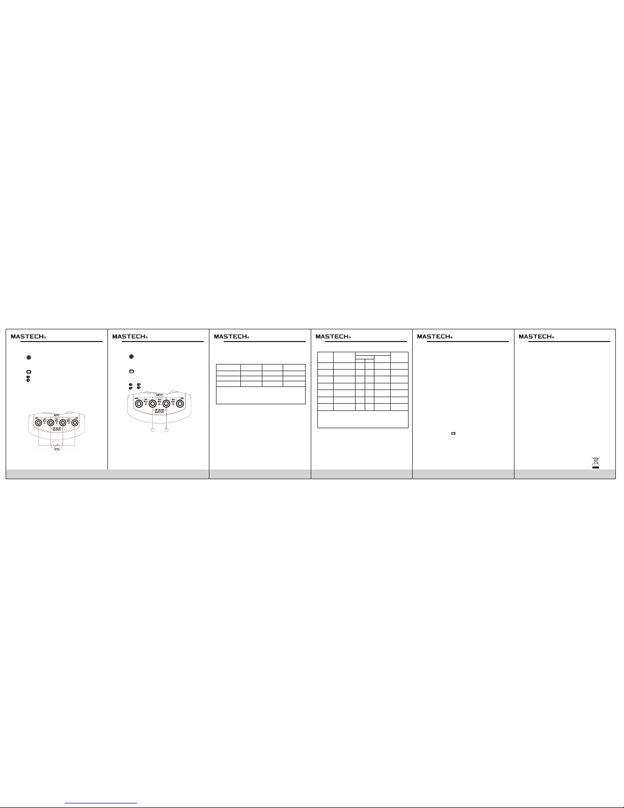
To simul ate an RTD , proce ed as fol lows:
1. Pre ss to tur n on the po wer.
2. If th e calib rator i s in inpu t mode (I NPUT on th e
disp lay), p ress “I NPUT/ OUTPU T” once . Make su re
the di splay s hows OU TPUT.
3. Pre ss to sel ect the d esire d RTD type .
4. Con nect te st lead s to the te rmina ls of the RT D
meas uring d evice a s shown . Use onl y the two c enter
outp uts.
5. Pre ss or to ad just th e value f or outp ut.
Simu latin g an RTD or R esist ance
RTD DE VICE IN PUT
Spec ifica tions a re base d on a one ye ar cali brati on cycl e
and ap ply for a mbien t tempe ratur e from +1 8°C to +2 8°C
unle ss stat ed othe rwise .
RANGE
0.00Ω~400.00Ω
Input Accuracy
4 Wrie ± Ω
Output
Accuracy ± Ω
Allowable
Excitation (mA)
400.0Ω~1500.0Ω
1500.0Ω~3200.0Ω
0.1~3.0
0.05~0.8
0.05~0.4
0.1
0.5
1
0.1
0.5
1
Allowable Excitation is for Output mode only.
It shows the allowable excitation current from an ohmmeter or
RTD measurement device connected to the calibrator.
Excitation current from Calibrator: 0.2 mA.
Maximum input voltage: 30 V
RTD Sp ecifi catio ns
Allowable
Excitation
(mA)
OUTPUT
Accuracy (°C)
INPUT
RANGE°C (°F)
RTD TYPE
-200.0~800.0
(-328.0~1472.0)
-200.0~800.0
(-328.0~1472.0)
-200.0~800.0
(-328.0~1472.0)
-200.0~630.0
(-328.0~1166.0)
-200.0~630.0
(-328.0~1166.0)
Pt10 (385)
Pt50 (385)
Pt200(385)
Pt500(385)
Pt100(385)
1.5
0.3
0.3
0.2
0.2
4W
2W/3W
1.5
0.5
0.4
0.4
0.4
1.5
0.5
0.4
0.4
0.4
0.1~3.0
0.1~3.0
0.1~3.0
0.1~3.0
0.05~0.8
0.1~3.0
0.05~0.4
-200.0~630.0
(-328.0~1166.0)
-200.0~800.0
(-328.0~1472.0)
Pt1000(385)
Pt100
(385)JIS
0.2
0.3
0.4
0.4
0.4
0.4
Allowable Excitation is for Output mode only.
It shows the allowable excitation current from an ohmmeter or
RTD measurement device connected to the calibrator.
Excitation current from Calibrator: 0.2 mA.
Maximum input voltage: 30 V
Maxi mum vol tage ap plied b etwee n any ter minal a nd
eart h groun d or betw een any t wo term inals : 30V
Stor age tem perat ure: -4 0 to 60
Oper ation t emper ature : -10 to 5 5
Oper ation a ltitu de: 300 0 meter s maxim um
Temper ature c oeffi cient : 0.05× speci fied ac curac y per
for te mpera ture ra nges
-10 t o 18 and 2 8 to 55
Rela tive hu midit y: 95% up t o 30 ,7 5% up to 40 ,45%
up to 50 ,and 3 5% up to 55
Vibra tion: R andom 2 g ,5 Hz to 50 0 Hz
Shoc k: 1 mete r drop te st
Powe r requi remen ts: Sin gle 9 V bat tery (A NSI/N EDA
1604 A or IEC 6LR 61)
Size : 190mm L ×89mm W ×42mm H
Weigh t: Appro x. 350g
°C °C
°C °C
°C
°C °C °C °C
°C °C
°C °C
Main tenan ce
Cali brati on
Cali brate y our cal ibrat or once a y ear to en sure th at
it per forms a ccord ing to it s speci ficat ions.
Repl acing t he Batt eries
If the m eter di splay “ ” o n LCD, th e batte ry must b e
repl aced to m ainta in prop er oper ation . Follo wing
proc edure t o repla cing th e batte ry:
1. Pre ss POWE R key to OF F. Discon nect te st lead s from
any li ve sour ce and re move th e test le ads fro m the
inpu t termi nals.
2. Rem ove the s crews o n the bat tery co ver and o pen the
cove r.
3. Rem ove the e xhaus ted bat tery an d repla ce with a n ew
9V bat tery.
4. Don 't use th e meter b efore t he batt er cove r is in pla ce
and fa stene d fully.
Othe rs
1. Cle an your m eter wi th a damp c loth an d mild de terge nt.
Do not u se abra sives , solve nts, or a lcoho l.
2. If an y fault s or abno rmali ties ar e obser ved, th e meter
can no t be used a ny more a nd it has t o be chec ked out .
Mea suring a n RTD or Re sista nce
To measu re an RTD, p rocee d as foll ows:
1. Pre ss to tur n on the po wer.
2. If th e calib rator i s in simu late mo de (OUT PUT on the
disp lay), p ress “I NPUT/ OUTPU T” once . Make su re the
disp lay sho ws INPU T.
3. Pre ss to sel ect the d esire d RTD type .
4. Pre ss to sel ect a two -wire , three -wire , or four w ire
RTD inp ut conf igura tion. L ook for t he 2W, 3W, or 4 W
annu nciat or on the d ispla y to veri fy that t he
conf igura tion is s et corr ectly.
5. Con nect te st lead s to the RTD a s shown u p. Use tw o,
thre e, or fou r input s, depe nding o n the set ting of 2 W,
3W, or 4W o n the dis play.
6. Rea d value o n the met er.
RTD
TYPE
2W 3W 4W
RTD
TYPE
2W 3W 4W
 Loading...