


DiMAX Kehrschleifenmodul
DiMAX Reverse Loop Module
8157001

1. Einleitende Information
Beim Aufbau von Kehrschleifen oder
Gleisdreiecken in Modellbahnanlagen
kommt es unweigerlich zum Kurzschluss zwischen den beiden Gleisen.
Deshalb müssen in solche Gleisbilder
immer an beiden Einfahrpunkten
Trennstellen eingebaut werden. Um nun
einen einfachen Fahrbetrieb realisieren
zu können, verwendet man Kehrschleifenmodule, welche die Umpolung des
isolierten Gleisabschnitts automatisch
vornehmen. Das DiMAX Kehrschleifenmodul ermöglicht solch einen einwandfreien Betrieb in Kehrschleifen oder
Gleisdreiecken. Dies geschieht entweder
über die Sensorgleise, Gleiskontakte
oder „Kurzschlusserkennung“.
1. General Information
Reversing loops and wye junctions
inescapably produce a short circuit at
the entry or exit points. Therefore these
arrangements require to be electrically
isolated at the entry and exit points. To
facilitate a reversing loop operation a
module is required to take care of the
polarization of the loop section.
The DiMAX Reversing Loop Module
allowsaawlessoperationinreversing
loops or wye junctions. It can be operated by sensor tracks, track contacts or
conventional short cirquit detection.
1.1. Funktionsumfang
Das DiMAX-Kehrschleifenmodul bietet
mehrere Betriebsarten:
•Durch die Verwendung von zusätzlichen „Sensoren“ kann dieses Modul
kurzschlussfrei betrieben werden. Das
Modul erkennt vor der Einfahrt, ob
der isolierte Abschnitt richtig gepolt
ist und passt die Gleisspannung entsprechend an, bevor ein Kurzschluss
entsteht.
•Alternativ kann das Modul über die
oben beschriebene Kurzschlusserkennung betrieben werden. Dies hat
den Vorteil, dass weniger Kabel benötigt werden, der Materialverschleiss an
2
1.1. Summary of Functions
The DiMAX-reverse loop module features several operating modes:
•With additional sensor tracks installed,
the module operates without any short
circuits. The DiMAX reverse loop
module detects the polarization of the
entering train and adjusts the polarity
of the reversing loop section accordingly before the train enters the loop.
•Alternatively the module may be used
with the common short circuit detection. This requires less wiring however
the burn-off on the wheels and the
trackisincreasedsignicantly.
•A mixed operation with sensor tracks

Rädern und Gleisen ist jedoch erhöht.
•Ein Mischbetrieb aus Kontaktauslösung und Kurzschlusserkennung ist
ebenfalls möglich. Falls einmal ein
Kontakt aufgrund von Verschmutzung
nicht erkannt wird, ermöglicht die
Kurzschlusserkennung trotzdem einen
einwandfreien Betrieb. Die Kurzschlusserkennung kann durch eine
Steckbrücke im Modul aktiviert oder
gesperrt werden.
•Durch die Verwendung von zwei unabhängigen Umpolrelais ist immer ein
sicherer Anlauf beim Einschalten der
Anlage gewährleistet. Selbst wenn ein
Zug eine Trennstelle brückt, kann die
passende Polung immer hergestellt
werden. Das isolierte Gleisstück wird
in diesem Fall einfach etwas zeitverzögert zur Hauptanlage eingeschaltet.
•Durch eine zusätzlich mögliche Spannungsversorgung kann das Modul
auch auf analog gesteuerten Anlagen
verwendet werden. Hier darf allerdings
beim Einschalten kein Zug auf einer
Trennstelle stehen.
and short circuit detection is available.
In case a sensor track does not work
properly due to contaminated or corroded tracks, the short circuit detection will provide a correct operation at
all times. The short circuit detection
may be turned on/off with a jumper
inside the module.
•A reliable operation of the module
is guaranteed at all times as two
separate switching relays are utilized.
Even if a train bridges a disconnecting
point when the system is switched on,
the module will adjust to the correct
polarization. In this case the loop section will be powered up with a slight
delay to the main layout.
•The module may be operated in
analog layouts as well, utilizing an
additional separate power supply.
However, in analog operation no train
must bridge a disconnecting point
when the system is switched on.
1.2. Lieferumfang
•DiMAX Kehrschleifenmodul
•Bausatz für 4 Sensorgleise
•Bedienungsanleitung
1.2. Scope of Supply
•DiMAX Reverse Loop Module
•Kit for 4 sensor tracks
•Manual
3

2. Wichtige Informationen
zur Inbetriebnahme
•Es ist unbedingt darauf zu achten,
das der isolierte Gleisabschnitt immer
länger sein muss, als der längste
auf der Anlage verkehrende Zug mit
stromleitenden Rädern. Verwenden
sie nur Wagen mit Kunststoffachsen,
so gibt die längste Lok die Mindestgleislänge vor. Verwenden sie jedoch
Wagen mit Metallachsen oder gar
einer eigenen Stromaufnahme, so
muss die komplette Zuglänge in den
isolierten Abschnitt passen. Denn
jedes Metallrad kann auf einer Trennstelle die Isolierung überbrücken.
Werden dann beim Überfahren beide
Trennstellen gleichzeitig überbrückt,
kommt es wieder zum Kurzschluss der
auch von einem Kehrschleifenmodul
nicht beseitigt werden kann.
•Der Leitungsquerschnitt für das
Hauptgleis und die Kehrschleife sollten zwischen 1,5-2mm² liegen.
•Das Modul ist bedingt wetterfest. Die
empndlichenelektronischenBauteile
sind zwar wasserdicht vergossen,
trotzdem kann Feuchtigkeit die
Anschlussklemmen oder Kontakte zerstören. Das Modul sollte unbedingt an
einem geschützten Platz (z.B. in einem
Haus) untergebracht werden. Auch
größere Temperaturschwankungen
sollten unbedingt vermieden werden,
da dies zur Bildung von Kondenswasser führen kann.
2. Important information
•It is essential, that the isolated track
section is longer than the longest
train on the layout with cars that are
equipped with power pick-ups or
metal wheels. In case only cars with
plastic wheels are used, the maximum
length of the loop section may be
reduced to the length of the longest
locomotive on the layout. In case cars
with metal wheels or wheels with a
power pick-up are used, the length
of the loop must accommodate the
whole train. Each metal wheel bridges
the disconnecting points when passing. Bridging both the disconnecting
points at the entry point and the exit
point at the same time will result in
a short circuit condition that even
the reverse loop module is unable to
handle.
•The cable cross section for the main
track and the reverse loop should be
between 1.5-2mm².
•The waterproofness of the module
is limited. The sensitive electronic
components are sealed waterproof,
however the terminals and contacts
may be damaged by moisture and humidity. The module should be placed
in a protected and dry environment
(e.g. a model house). Major temperature variations may cause condensed
water which may result in damage to
the module.
4

•Bei Verwendung der Sensorgleise
im Freien muss immer auf eine einwandfreie Funktion geachtet werden.
Verschmutzungen an den Trennstellen
können zu Kriechströmen führen,
welche dann ein fehlerhaftes Schaltverhalten erzeugen. Für eine größere
Störsicherheit können sie zusätzlich
die beiliegenden Dioden in die Sensorleitungen einbauen (siehe Bild 3).
•Das Modul darf nur für die in der Anleitung genannten Funktionen genutzt
werden. Ein anderweitige Verwendung, kann zur Zerstörung führen.
•Auslieferungszustand: Brücke geschlossen für Sensorgleise
•Dieses Modul ist kein Spielzeug !
•Keep the sensor tracks and the dis-
connecting points clean at all times,
especially during outdoor operation.
Contamination of the disconnecting
points may result in creeping current
and subsequently in malfunction of
the module. To improve operation
the diodes provided with the module
may be placed in the sensor lines (see
Illustration 3).
•The module must only be connected to components described in
this manual. Connecting this unit to
other components even if the plugs
are matching may result in serious damage to the module or other
components.
•Delivery status: Jumper closed for
Short circuit-detection OFF
•This module is not a toy!
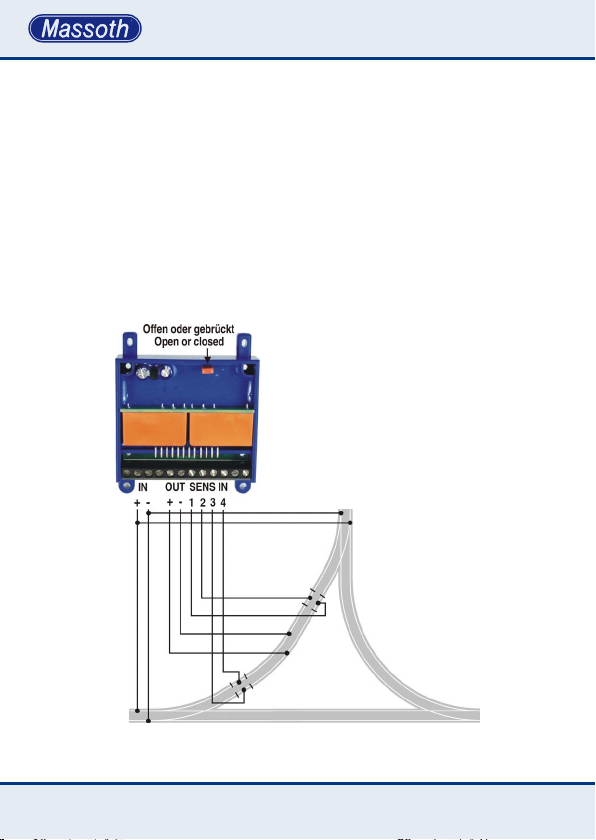
Abbildung 1: Beschreibung der Anschlüsse
Illustration #1: Contact allocation
5

Abbildung 2: Montagebeispiel für die Sensorgleise
Illustration #2: Sensor track installation
6

Abbildung 3: Verwendung der Dioden für höhere Störsicherheit
Illustration #3: Diode installation for improved operation
3. Anschlüsse
3.1. Kurzschlussfreie digitale
Kehrschleifen über Sensorgleise
Durch den Einbau der beiliegenden
Sensorgleisstücke in die Trennstellen
ist ein kurzschlussfreier Betrieb der
Kehrschleife möglich. Verschalten sie
die Gleise entsprechend dem Anschlussplan. Achten sie dabei unbedingt
auf die richtige Verkabelung der Sensorgleise. Nur dann ist ein einwandfreier
Betrieb möglich. Ist die Steckbrücke
offen (Bild 1), wird zusätzlich die interne
Kurzschlusserkennung aktiviert. Wenn
sie mehrere Kehrschleifen gleichzeitig nutzen möchten, müssen sie die
Kurschlusserkennung durch Schließen
der Steckbrücke deaktivieren. Statt der
3. Hook up
3.1. Short circuit free digital reverse
loop with sensor tracks
Install the sensor track components according to the wiring and installation
diagram (Illustration 4). Make sure the
hook-up is done correctly to ensure a
proper operation. In case the jumper
is removed (Illustration 1), the short
circuit detection is activated additionally. Operating multiple reverse loop
modules at the same time requires the
jumper to be set (short circuit recognition deactivated). Track contacts (reed
contacts) may be utilized instead of the
sensor tracks. This may improve the
interference resistance but requires a
magnet under each locomotive.
7

Abbildung 4: Digitale Kehrschleife mit Sensorgleisen
Illustration #4: Digital reverse loop with sensor tracks
Abbildung 5: Digitale Kehrschleife mit Gleiskontakten
Illustration #5: Digital reverse loop with track contacts
8

Sensorgleise können auch Gleiskontakte verwendet werden. Dies erhöht
eventuell die Störsicherheit, benötigt
aber unter jeder Lok einen Magneten zur
Auslösung.
3.2. Digitale Kehrschleifen mittels
Kurzschlusserkennung
In dieser Schaltvariante benötigen
sie nur eine beidseitige Trennstelle in
beiden Einfahrten. Verschalten sie die
Gleise entsprechend dem Anschlussplan. Beachten sie jedoch bitte, dass
hier ein erhöhter Verschleiß durch Abbrand an Gleisen und Rädern entstehen
Abbildung 6: Digitale Kehrschleife mit Kurzschlusserkennung
Illustration #6: Digital reverse loop with short circuit detection
3.2. Digital reverse loops with short
circuit detection
This mode requires the reverse loop
section to be completely isolated from
the main layout at the entry and exit
points. Hook up the module according
to the wiring diagram. Please note that
this operation results in a higher burn
off at the wheels and the tracks. Operat-
9
kann. Wenn Sie mehrere Kehrschleifen
nutzen, darf immer nur eine aktiv zur
gleichen Zeit befahren werden.
ing multiple reverse loops in one layout
requires that only one loop at a time
may be used.
3.3. Digitales Gleisdreieck
Das Gleisdreieck verursacht durch sein
Gleisbild ebenfalls einen Kurzschluss.
Deshalb muss auch hier ein Schenkel
des Dreiecks durch einen isolierten
Abschnitt getrennt werden. Sie können
dieses ebenfalls über Sensorgleise oder
auch über die Kurzschlusserkennung
Abbildung 7: Digitales Gleisdreieck mit Sensorgleisen
Illustration #7: Digital wye junction with sensor tracks
3.2. Digital wye (triangular) junction
A wye junction also causes a short circuit. Therefore one side of the triangle
must provide an electrically isolated
section. The choice of operation is with
sensor tracks or short circuit detection.
Pleasecheckthersttwoexamplesof
the reverse loop for further information.
10

betreiben. Weitere Hinweise hierzu
ndensieunterdenbeidenersten
Schaltbeispielen.
3.4. Analoge Kehrschleife
Bei der analogen Kehrschleife wird im
Gegensatz zum Digitalbetrieb nicht die
Kehrschleife sondern das Hauptgleis
über das Modul umgepolt. Somit ist
hier ebenfalls ein automatischer Betrieb
möglich. Es sind jedoch einige Besonderheiten zu beachten. Es wird eine
Hilfsspannung (14 - 24 V DC) benötigt,
welche das Modul immer versorgt.
Beim Überfahren der Trennstellen ist
eine Mindestfahrspannung von 5V
nötig, um eine einwandfreie Sensorik zu
ermöglichen. Die zusätzlichen Entstördioden dürfen nicht verwendet werden.
Die Kehrschleife muss immer in der
gleichen Richtung durchfahren werden.
Alternativ kann auch hier mit Gleiskontakten statt Sensorgleisen gearbeitet
werden.
3.4. Analog reverse loop
The analog reverse loop reverses the
main track polarity instead of the loop
polarity. For an automatic operation however a few details have to be
observed. A separate power supply is
required to power the module (14 - 24
V DC). A minimum driving voltage of 5
Volts is required to ensure a safe sensor
operation. Additional diodes must not
be used. The reverse loop must always
be operated in the same direction.
Alternatively the use of track contacts
instead of sensor tracks is possible.
11

Abbildung 8: Analoge Kehrschleife mit Sensorgleisen
Illustration #8: Analog reverse loop with sensor tracks
12

Abbildung 9: Analoge Kehrschleife mit Gleiskontakten
Illustration #9: Analog reverse loop with track contacts
13

4. Technische Daten
Spannungsversorgung: 0-27 Volt
(DC=), 14-27 Volt (Digitalspannung)
Hilfsspannung im Analogbetrieb:
14-27 V (DC=)
Maximaler Schaltstrom : 8 Ampere
dauerhaft (16 Ampere kurzzeitig)
maximale eigene Stromaufnahme :
ca. 50mA
Betriebstemperatur: -20 .. 50° C
Hinweis zur Temperatur: Um Kondenswasserbildung zu vermeiden, benutzen
Sie die Elektronik bei Temperaturen
unter 0°C nur, wenn diese vorher aus
einem beheizten Raum kommt. Die
Wärme die während des Fahrbetriebs
erzeugt wird, reicht aus um Kondenswasserbildung zu verhindern.
4. Technical specications
Power Supply: 0 - 27V (DC=), 14-27
Volt (DCC)
Helping voltage in Analogue mode:
14-27 Volts (DC=)
Maximum Switching current: 8 Amps
continuous (16 Amps momentary)
maximum module current drain:
appr. 50mAmps
Temperature Range: -20° .. 50° C
-4° .. 125° F
Note regarding the operating temperature: to prevent the production of
condensed water, use the Multi-RC
Module in freezing conditions only if
it was previously stored in a heated
environment. The heat produced dur-
ingoperationissufcienttoprevent
condensed water.
4.1. Gewährleistung & Kundendienst
MASSOTH gewährt die Fehlerfreiheit
dieses Produkts im Rahmen der
gesetzlichen Vorgaben, mindestens
jedoch für 1 Jahr ab Kaufdatum. Um
Reparatur- oder Serviceleistungen in
Anspruch zu nehmen, übergeben Sie
das Produkt bitte Ihrem Fachhändler
oder senden es direkt an den Hersteller.
Unfreie Sendungen werden nicht angenommen. Eine Kopie des Kaufbelegs
sowie ein einwandfreies Prüfetikett auf
dem Produkt werden vorausgesetzt.
Für Schäden durch unsachgemäße
14
4.1. Warranty & Customer Support
MASSOTH warrants this product against
defects in materials and workmanship
under the relevant statutory provisions at least for one year from the
original date of purchase. For warranty
service please return the product to
you dealer or send it directly to the
manufacturer. Return shipping charges
are not covered. A copy of the receipt
and proper compliance label on the
product is required. Normal wear and
tear,consumermodicationsaswell
as improper use or installation are not

Behandlung oder Fremdeingriff oder
Veränderung des Produkts besteht kein
Garantieanspruch. Der Anspruch auf
Serviceleistungen erlischt unwider-
ruich.Verschleißteilesindvonder
Garantieleistung ausgeschlossen.
AufunsererInternetseitendenSie
die jeweils aktuellen Broschüren, Produktinformationen, Dokumentation und
Softwareprodukte rund um MASSOTH
Produkte. Irrtümer und Änderungen
vorbehalten.
4.2. Hotline
Serviceanfragen richten Sie bitte an:
covered. Peripheral component damage
is not covered by this warranty. Valid
warranty claims will be serviced without
charge within the warranty period.
Please check our web site for up to
date brochures, product information,
documentation and software updates.
Errors and changes excepted.
4.2. Hotline
For technical support contact:
Massoth Elektronik GmbH
Mo 14:00-17:30 sowie Do 8:00-12:00
FON +49 (0)6151-35077-38
FAX +49 (0)6151-35077-44
hotline@massoth.de
Massoth Elektronik GmbH, Germany
Mo 2:00-5:30 p.m.
Thu 8:00-12:00 a.m.
FON +49 (0)6151-35077-38
FAX +49 (0)6151-35077-44
hotline@massoth.de
15

QUALITY
MADE IN
GERMANY
Massoth Elektronik GmbH
Frankensteiner Str. 28 · D-64342 Seeheim · Germany
FON: +49 (0)6151-35077-0 · FAX: +49 (0)6151-35077-44
eMail: info@massoth.de · www.massoth.de
RoHS
032377o
COMPLIANT
991025 BDA 8157001 2015.02
 Loading...