

Page 1
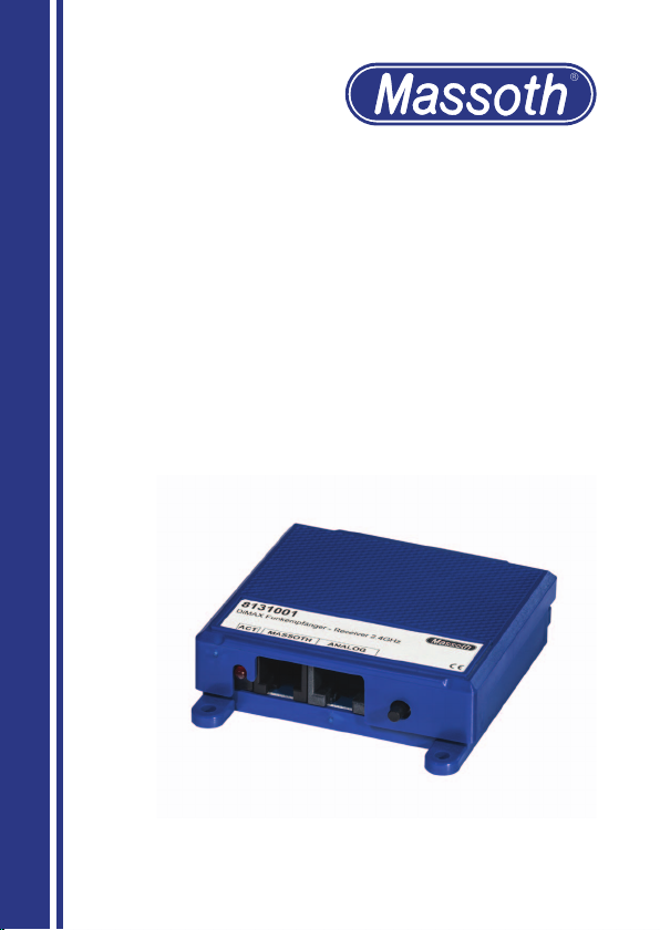
DiMAX Funkempfänger 2.4GHz
DiMAX Receiver 2.4GHz
8131001
Page 2
WICHTIGER HINWEIS
Sehr geehrte Kunden, wir empfehlen diese
Produktdokumentation und vor allem auch
die Warnhinweise vor der Inbetriebnahme
gründlich zu lesen und diese zu Beachten.
IMPORTANT NOTE
Dear customer, we strongly recommend
that you read this manu al and the warning
notes thoroughly before installing and
operating your decoder.
1. Einleitende Information
Werte Kunden, mit dem DiMAX
Funkempfänger 2,4GHz haben sie
ein hochwertiges Produkt „Made
in Germany“ erworben. Dieser
kann mit bis zu vier Funksendern
betrieben werden. Die Reichweite
ist von den örtlichen Gegebenheiten abhängig. Fremde Sender
auf gleicher Frequenz sowie
Hindernisse zwischen Sender und
Empfänger (z.B. Wände) können
den Funkverkehr einschränken.
1.1 Lieferumfang
•DiMAX Funkempfänger
•Verbindungskabel 4pol. und 8 pol.
•Bedienungsanleitung
2. Anschluss
Verwenden sie zum Anschluss das
passende Kabel:
•4polig (6poliger Stecker) für
Digital/Massoth-Bus (Blaue-LED)
•8polig (8poliger Stecker) für
Analog (Rote-LED)
Stecken sie eines der Kabel in die
entsprechende Buchse und in die
1. Dear Customer,
With the DiMAX RC Receiver
2.4GHz, you have purchased a
high quality product „Made in
Germany“. It can be operated with
up to four transmitters. Its reach
depends on location`s conditions.
Other transmitters using the same
frequency or other obstacles
between transmitter and receiver
(e.g. walls) may reduce or limit
radiotrafc.
1.1 Scope of Supply
•DiMAX RC Receiver
•Connecting cable 4pin and 8pin
•Instruction Manual
2. Connection
Please use the designated cable
for connecting:
•4pin (6pin housing) for
Digital/Massoth-bus (blue LED)
•8pin (6pin housung) for
analog (red LED)
Connect one of the cables to
the appropriate socket and to
2
Page 3
Zentrale bzw. den Analogregler.
ACHTUNG
Es dürfen niemals beide Kabel gleichzeitig
angeschlossen sein.
the central station or the analog
control unit.
ATTENTION
Never connect both cables at the same time.
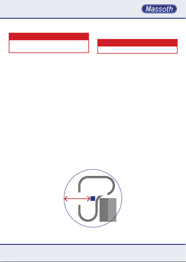
2.1 Standort und Reichweite
Stellen sie den Funkempfänger
so auf, dass die Reichweite von
keinem Punkt ihrer Anlage aus
überschritten wird und möglichst
wenige Hindernisse zwischen
Sender und Empfänger sind. Der
Empfänger sollte mindestens einen
Meter Abstand zu Trafos, Digitalzentrale, Booster und Gleisen
haben. Verlegen sie das Buskabel
nicht parallel zu den Gleisen. Die
Reichweite des Funkempfängers
beträgt etwa 50 Meter, im Freilandbetrieb auch deutlich mehr. Probieren Sie ggf. mehrere Positionen
aus um den optimalen Standort zu
ermitteln.
ca. 50m
ca. 164ft
Abbildung 1: Standort und Reichweite
Illustration #1: Positioning and Range
2.1 Positioning and Range
Place the RC Receiver in a location
so that it will not overload the
maximum distance between it
and any point of your model
train layout and ensure that there
are minimal obstacles between
transmitter and receiver. The RC
Receiver should have a minimum
distance of one meter to transformer, central station, booster and
tracks. Do not install the bus cable
parallel to the tracks. The reach of
the RC Receiver is 50 meters, even
more on open land. If necessary,
justtryafewdifferentspotstond
the optimal location.
8131001
Haus
House
3
Page 4
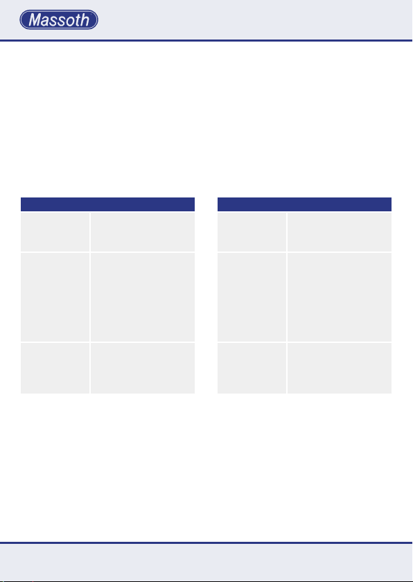
2.2 LED Aktivität
Der Betriebszustand des Funkempfängers wird durch die
STATUS LED in der Buchse des
jeweiligen Anschlusses angezeigt. Die LED links neben den
beiden Steckbuchsen zeigt den
Betriebszustand des Funkempfängers an.
2.2 LED Activity
The operation mode of the RC
Receiver is displayed on the different status LEDs of the connecting
sockets. The LED on the left of the
two sockets shows the operational readiness of the receiver by
permanent lighting.
Betriebszustand der STATUS LED
An
(dauerhaft)
Blinken
symmetrisch
schnell
Blinken
symmetrisch
langsam
Regulärer Betrieb
mit einem oder mehreren
Funksendern
Empfänger sucht nach
neuen Teilnehmer z. B.
beim ersten Einschalten,
nach Werksreset oder
wenn ein neues Gerät
über den Taster angemeldet werden soll.
Funkempfänger Standby
Nach dem Einschalten
oder wenn längere Zeit
kein Sender aktiv ist.
3. Funkverbindung Herstellen
Stellen sie sicher, dass sie einen
Navigator mit dem 2,4GHz-Funksystem verwenden. Für die Erstanmeldung oder nach einem Reset
müssen sie lediglich den Navigator
in den Verbindungmodus bringen.
DieEinstellungenhierzundensie
im Menü Ihres DiMAX Navigators.
4
Operating State of the STATUS LED
On
(static)
ashing
symmetric
fast
ashing
symmetric
slow
Regular operation with
one or more transmitters
Receiver searches for
transmitters, e.g. when
rstswitchedon,after
factory reset or if a new
device is to be registered
via the push-button.
Radio receiver Standby
after switching on or if
no transmitter is active
for a long time.
3. Establish radio connection
Please ensure to use a 2,4GHz
Navigator system. You only need
to operate the navigator on the
connectingmodeforrstregistrationorafterareset.Youndthe
required setting in the Navigators
menu. For further registrations
oriftherstregistrationwas
Page 5

Für weitere Anmeldungen oder
wenn die Erstanmeldung nicht
erfolgreich war, drücken sie den
Taster am Empfänger ca. fünf Sekunden bis die Status-LED schnell
symmetrisch blinkt.
Während des Blinkens können
sie einen weiteren Navigator
anmelden. Bereits angemeldete
Funkteilnehmer können sich ohne
Anmeldung wieder einloggen.
Sofern dies nicht funktioniert ist
entweder die Verbindungsliste voll
(mehr als vier Sender in der Liste)
oder ein Reset wurde vorgenommen. Aus der Verbindungsliste
des Systems wird immer der
älteste Navigator gelöscht. Bis zu
zwei Navigatoren können vor dem
Entfernen aus der Verbindungsliste
gesichert werden. Hierfür muss im
Menü Ihres DiMAX Navigators die
Option PRI (Priority) ausgewählt
werden.
unsuccessful, please press the
push button on the receiver for
5 seconds until the status LED is
symmetrically blinking fast.
While blinking, you can register another navigator. Already
registered radio participants can
login without registration. If this
does not work, it can either be
because the maximum capacity of
users is reached (more than four
transmitters on the list) or a reset
has been initiated. The systems
connection list always deletes the
oldestnavigatorrst.Uptotwo
navigators can be saved before
deleting from the connection list.
For this, you have to select the PRI
(Priority) option in your navigator
menu.
4. ID - Identikationsnummer
Der Funkempfänger ist passiv und
verfügt über keine vom Nutzer
einzustellende ID. Mit der Anmeldung eines Navigators wird dieser
von der Zentrale erkannt und ihm
automatisch eine ID zugewiesen.
4. ID - Identication Number
The RC Receiver is passive and
does not require an ID that can be
conguredbytheuser.Whenregistrating a Navigator, the central
stationautomaticallyidentiesthe
receiver and allocates an ID.
5
Page 6
5. Betrieb mehrerer Navigatoren
Die ID Vergabe erfolgt automatisch
im Bereich der voreingestellten ID
Gruppe. In der Grundeinstellung
(DIP 3=OFF) werden die ID 28 - 25
vergeben. Funk ID 1 entspricht
dann ID 28, Navigator ID 4 entspricht ID 25. Beim Einsatz eines
zweiten Funkempfängers ist bei
diesem DIP 3 auf ON zu stellen.
Hier werden der Funk ID 1 - 4
die ID 20 - 17 zugeordnet. Somit
können 2 Empfänger gleichzeitig
bis zu 8 Navigatoren betreiben. Es
kann auch ein 2,4GHz Funkempfänger und ein Funkempfänger
mit 433MHz-Technik (Artikelnummer: 8133101) parallel betrieben
werden. Auch hier ist die ID
Gruppe unterschiedlich zu wählen.
Wird nur ein 2,4GHz Funkempfänger mit maximal vier Navigatoren
betrieben kann dieser im Auslieferungszustand (alle DIP-Schalter
auf OFF) verwendet werden.
5. Operating multiple Navigators
The ID assignment takes place
automatically in in the range of the
preset ID group. With the basic
setting (DIP3=OFF) ID 28 - 25
are allocated. Navigator ID 1 then
equals 28, ID 4 equals 25. If a second receiver is operated, the DIP
switch has to be set to DIP 3 = ON.
This will allocate the IDs numbers
20 - 17 to the Navigator IDs 1 - 4.
This way, 2 Receivers can operate
up to 8 Navigators. You may also
operate a 2,4GHz Receiver and a
Receiver with 433MHz technology
(#8133101) at the same time. In
this case you also need to select
different ID groups. If only one
2,4GHz RC receiver is operated
with a maximum of four navigators, it can be operated on the
factory setting (all DIP switches
OFF).
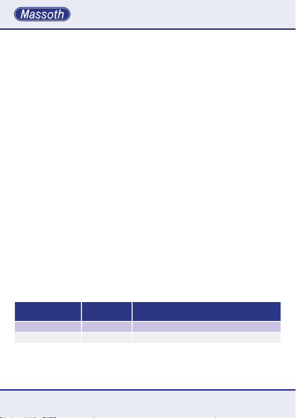
ID Gruppe
ID Group
A OFF 28-25
B ON 20-17
6
DIP 3
ID Bereich
ID Range
Page 7
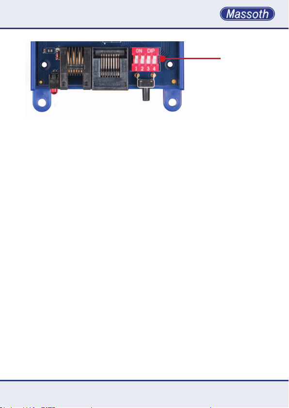
Abbildung 2: DIP-Schalter zur Einstellung des Funkkanals
Illustration #2: DIP-Switch to select RC-channel
DIP-Schalter
DIP-Switch
5.1 Betriebsart
Unter LogIn 2.4 stehen folgende
Betriebsarten zu Verfügung:
•STD: Der Navigator zeigt bei
Anmeldung STD (Standard) im
Display. Bei dieser Anmeldeform
wird bei voller Verbindungsliste
der älteste Navigator aus der Liste
gelöscht.
•PRI: Der Navigtor zeigt bei Anmeldung PRI (Priority) im Display. Bis
zu zwei Navigatorn können unter
dieser Option angmeldet werden.
Dieser werden dann auch bei voller
Verbindungsliste nicht gelöscht.
Sind bereits zwei Navigatoren mit
PRI angemeldet, meldet sich ein
dritter Navigator automatisch als
STD an.
•DIR: Der Navigtor zeigt bei Anmeldung DIR (Direktfunk) im Display.
Diese Funktion steht aktuell noch
nicht zur Verfügung.
5.1 Operation Mode
The following operating modes are
available under LogIn 2.4:
•STD: The Navigator shows STD
(standard) in the display when logging in. With this mode, the oldest
Navigator is deleted from the list
when the connection list is full.
•PRI: The Navigtor shows PRI
(priority) in the display during
login. Up to two Navigators can
be logged in under this option.
They will not be deleted even if the
connection list is full. If two Navigators are already logged in with
PRI, a third Navigator automatically logs in as STD.
•DIR: The Navigtor shows DIR
(direct control) in the display.
This function is not yet available.
7
Page 8
6. Zurücksetzen auf
Werkseinstellungen
Zum Löschen der Verbindungsliste
kann ein Werksreset durchgeführt
werden. Dazu ist das Gehäuse
durch das Lösen der vier Schrauben auf der Unterseite zu öffnen.
Auf der Platine sind alle DIP-Schalter auf ON zu stellen und beim
Einstecken des Kabels ist der
Taster gedrückt zu halten. Nach
einer Sekunde kann der Empfänger
wieder von der Zentrale getrennt
werden. Stellen sie die Dipschalter wieder auf die vorherige
Einstellung. Nun können wieder
Navigatoren wie oben beschrieben
angemeldet werden.
6. Reset to factory defaults
In order to fully delete the connection list you can initiate a factory
reset. The housing has to be opened by loosening the four screws
on the bottom. All DIP switches
on the circuit board have to be set
to ON and the push button has to
be kept pressed while connecting
the cable. After one second the RC
Receiver can be separated from
the central station. Now reset the
DIP switches to their former setting. You can then go ahead and
register navigators as described
above.
7. Firmware-Update
Der DiMAX Funkempfänger kann
mit der neuesten Firmware ausgestattet werden. Dazu muss der
Funkempfänger mit der MassothBus Buchse am PC-Modul oder
der Zentrale verbunden werden.
ACHTUNG
Es dürfen keine weiteren Anschlüsse
verbunden sein.
Starten Sie am PC die DiMAX-Updatesoftware und laden Sie die aktuelle Software für den Empfänger.
Es folgt die Eingabe der seriellen
Schnittstelle am PC (COM-Port).
8
7. Firmware-Update
The DiMAX RC Receiver can
be equipped with the newest
rmware.Youneedtohookupthe
RC Receiver to the Massoth Bus
connector on the PC-Module or
the central station.
ATTENTION
No further connections must be connected.
Start the Update-software on your
computer and load the up-to-date
software for the RC Receiver. The
serial interface is then submitted
on the PC (COM-Port).
Page 9

Während dem Update blinken die
rote und blaue Buchsen-LED des
Funkempfängers gleichmäßig. Der
Funkempfänger ist nun mit der
neusten Software ausgestattet und
betriebsbereit.
During the update, the blue and
red LED of the RC Receiver are
evenly blinking. The RC Receiver
is now equipped with the newest
software and ready-to-operate.
Tritt während dem Update ein
Fehler auf, wird dies am Bildschirm angezeigt und das Update
wird abgebrochen. Dabei blinken
die LED des Empfängers dreimal.
Der Funkempfänger erwartet beim nächsten Neustart
automatisch die Installation der
neuesten Software, erkennbar
durch das 3-fach schnelle Blinken
der beiden Buchsen-LED beim
Starten des Funkempfängers.
8. Technische Daten
• Versorgungsspannung
5...24 V DC
(je nach Zentrale oder Regler)
• Stromaufnahme
30 mA im Ruhezustand
• Frequenzband
2,402...2,480GHz
• Sendeleistung
max. 10mW typ 1mW 0-9,5dBm
• Temperaturbereich
-20 ... +45°
• Abmessungen (L x B x H)
68 x 78 x 20 mm
If, during the update, an error
occurs, it will be displayed on the
screen and the update is discontinued. The LEDs of the receiver
will blink three times. The RC
Receiver will expect the update
at the next start and will show
this by the triple fast blinking of
both socket LEDs.
8. Technical Specications
• Power Supply
5...24V DC (depending on Central
Station or controller)
• Current consumption
30mA in idle mode
• Frequency band
2,402...2,480GHz
• Transmitting power
max. 10mW typ 1mW 0...9.5dBm
• Temperature range
-20 ... +45°
• Dimensions
68 x 78 x 20 mm
9
Page 10

• Regulatory Information
This device contains:
FCC ID: WAP4110
IC: 7922A-4110
(Please see backside of documentation for Regulatory Information)
9. Der Betrieb ist an folgenden
Geräten zulässig:
•DiMAX 1200Z, 1210Z, 800Z
•LGB® MZS III Zentrale 55006
•LGB® Fahrregler 51097
•PIKO® Zentrale 35010
•PIKO® Fahrregler 35002
Hinweis zur Temperatur: Benutzen
sie die Elektronik bei Temperaturen unter 0°C nur, wenn diese
vorher aus einem beheizten Raum
kommt. Die Wärme während des
Betriebs reicht aus um die Bildung
von Kondenswasser zu verhindern.
10. Gewährleistung & Kundendienst
MASSOTH gewährt die Fehlerfreiheit dieses Produkts im Rahmen
der gesetzlichen Vorgaben,
mindestens jedoch für ein Jahr ab
Kaufdatum. Um Reparatur- oder
Serviceleistungen in Anspruch
zu nehmen, übergeben Sie das
Produkt bitte Ihrem Fachhändler
oder senden es direkt an den
Hersteller. Unfreie Sendungen
9. Operating with the following
components is allowed:
•DiMAX 1200Z, 1210Z, 800Z
•LGB® MZS III Zentrale 55006
•LGB® Fahrregler 51097
•PIKO® Zentrale 35010
•PIKO® Fahrregler 35002
Note on temperature: Do only use
the electronics in under 0°C temperatures if the hardware comes
out of a heated room. The heat
that is produced during operation
sufcestopreventcondensation.
10. Warranty & Service
MASSOTH warrants this product
against defects in materials and
workmanship for one year from
the original date of purchase.
Other countries may have different
legal warranty situations. Normal
wearandtear,consumermodications as well as improper use
or installation are not covered.
Peripheral component damage is
10
Page 11

werden nicht angenommen. Eine
Kopie des Kaufbelegs sowie ein
einwandfreies Prüfetikett auf dem
Produkt werden vorausgesetzt.
Für Schäden durch unsachgemäße
Be handlung, Fremdeingriff oder
Veränderung des Produkts besteht
kein Gewährleistungsanspruch.
Der Anspruch auf Servicelei-
stungenerlischtunwiderruich.
Verschleißteile sind von der Gewährleistung ausgeschlossen. Auf
unsererInternetseitendenSie
die jeweils aktuellen Broschüren,
Produktinformationen, Dokumentation und Softwareprodukte rund
um MASSOTH Produkte. Irrtümer
und Änderungen vorbehalten.
not covered by this warranty. Valid
warranty claims will be serviced
without charge within the warranty
period. For warranty service please
return the product to you dealer or
send it directly to the manufacturer. Return shipping charges are
not covered by MASSOTH. Please
include your proof of purchase
with the returned goods. Please
check our website for up to date
brochures, product information,
documentation and software
updates. Errors and changes
excepted.
11. Hotline
Gerne stehen wir Ihnen für
Rückfragen zu diesem Produkt zur
Verfügung. Sie erreichen uns per
eMail unter: [email protected]
Die telefonische Hotline ist unter
+49 (0)6151-35077-38
zu bestimmten Zeiten geschaltet.
Die Telefonzeiten werden angesagt.
11. Hotline
We will be happy to answer your
questions about this product.
You may reach us via eMail at:
The phone hotline is available at
+49 (0)6151-35077-38
atspecicoperationalhours.
Operational hours are announced.
11
Page 12
REGULATORY INFORMATION
1. FCC Information (USA): This device contains FCC ID: WAP4110.
The device CYBLE-224110-00 complies with Part 15 of the FCC Rules. The
device meets the requirements for the modular transmitter approval as
detailed in FCC public Notice DA00-1407. Transmitter Operation is subject to
the following two conditions: (1) This device may not cause harmful interference, and (2) This device must accept any interference received, including
interference that may cause undesired operation.
2. ISED Information (Canada): This device contains IC: 7922A-4110.
The device CYBLE-224110-00 including the built-in chip antenna complies
with Canada RSS-GEN Rules. The device meets the requirements for
modular transmitter approval as detailed in RSS-GEN. Operation is subject to
the following two conditions: (1) This device may not cause harmful interference, and (2) This device must accept any interference received, including
interference that may cause undesired operation.
L‘appareil CYBLE-224110-00, y compris l‘antenne intégrée, est conforme aux
Règles RSS-GEN de Canada. L‘appareil répond aux exigences d‘approbation
de l‘émetteur modulaire tel que décrit dans RSS-GEN. L‘opération est
soumise aux deux conditions suivantes: (1) Cet appareil ne doit pas causer
d‘interférences nuisibles, et (2) Cet appareil doit accepter toute interférence
reçue, y compris les interférences pouvant entraîner un fonctionnement
indésirable.
3. MIC Japan
CYBLE-224110-00iscertiedasamodulewith
typecerticationnumber203-JN0568.
4. KC Korea
CYBLE-224110-00iscertiedforuseinKoreawith
certicatenumberMSIP-CRM-Cyp-4110.
QUALITY
MADE IN
GERMANY
RoHS
COMPLIANT
Massoth Elektronik GmbH
Frankensteiner Str. 28 · D-64342 Seeheim · Germany
FON: +49 (0)6151-35077-0 · FAX: +49 (0)6151-35077-44
eMail: [email protected] · www.massoth.de
032377o
991113 2019.05
BDA 8131001
 Loading...