

Page 1
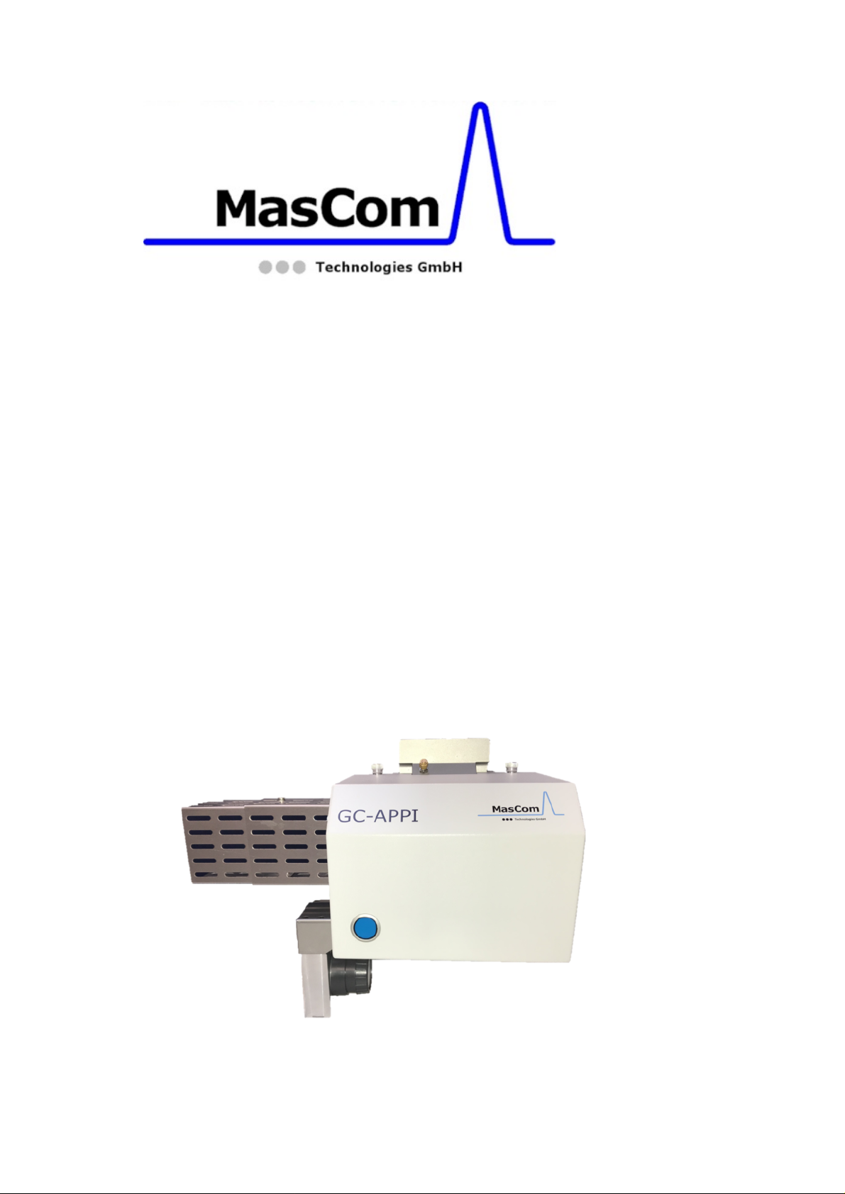
Operating Manual
GC-APPI Inferface for:
Orbitrap FusionTM TribridTM MS,
and Orbitrap FusionTM Lumos
TribridTM MS
P/N: MC513000
Revision B
TM
Page 2

GC-APPI-Interface
© 2018 MasCom Technologies GmbH
Original Operating Instructions
The manual describes the installation and
operation of the GC-APPI-Interface for the
Orbitrap Fusion series MS systems.
Revision History:
Revision A: published in December 2018
Revision B: published in May 2019
MasCom Technologies GmbH
Sophie-Germain-Str. 4
D-28201 Bremen
Germany
Tel.: +49-421-572970
[email protected]
Trademarks
Fusion, Tribrid, Lumos, Orbitrap,
Thermo Scientific, Trace, Trace GC Ultra, and
Xcalibur are registered trademarks of Thermo
Fisher Scientific Inc. in the United States.
GC-APPI Interface Page 2
Page 3

Safety Instructions
Please read all of these instructions carefully
before starting the installation of the GC-APPIInterface and follow all recommendations.
1) Set the mass spectrometer to “off” mode.
2) Cool down the heated capillary of the
mass spectrometer
3) When removing the ESI sprayer be aware
that the heated capillary may still be hot.
4) Caution: don’t squeeze your fingers when
closing the cover of the interface
5) Please use nitrile gloves, or similar ones,
to ensure your own safety and avoid
contamination.
6) Always unplug the heater cable before
detaching the interface from the mass
spectrometer. Never connect the
interface heater cables when the APPI
interface is not attached to the mass
spectrometer. There is a high risk of overheating because the fan is not running.
Caution: hot surface with high risk to get burned!
During operation, the Interface housing may warm
up to 65 deg. C. When the interface is opened, the
heater is automatically turned off but the source
may still be very hot (up to 330 deg. C, depending
on the operating temperature).
We also recommend watching the GC-APPIInterface installation video to familiarize yourself
with the procedure. This video has been provided
on a USB stick with the interface. Alternatively,
you can download it using the following link:
http://www.mascombremen.de/html/en/downloads/gc-appiinformation
GC-APPI Interface Page 3
Page 4
Important information
Any changes or modification to the GC-APPI
interface, undertaken without our consent, may
endanger the functionality and/or safety, and
will result in the termination of the declaration
of conformity.
Tools required for source switching
Changing from ESI to GC-APPI on the Exactive or
LTQ Orbitrap series instruments only requires a
few tools:
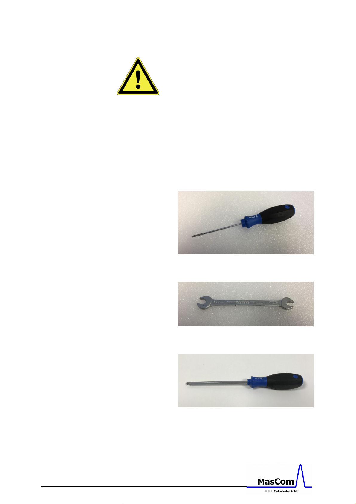
Figure A: Screwdriver for removing the spray cone
and for tighten the plug on the APPI lamp
Figure B: 5/16-wrench for the dopant gas
connection
Figure C: 6 mm Allen screwdriver for locking and
unlocking the interface on the Orbitrap Fusion
systems
GC-APPI Interface Page 4
Page 5
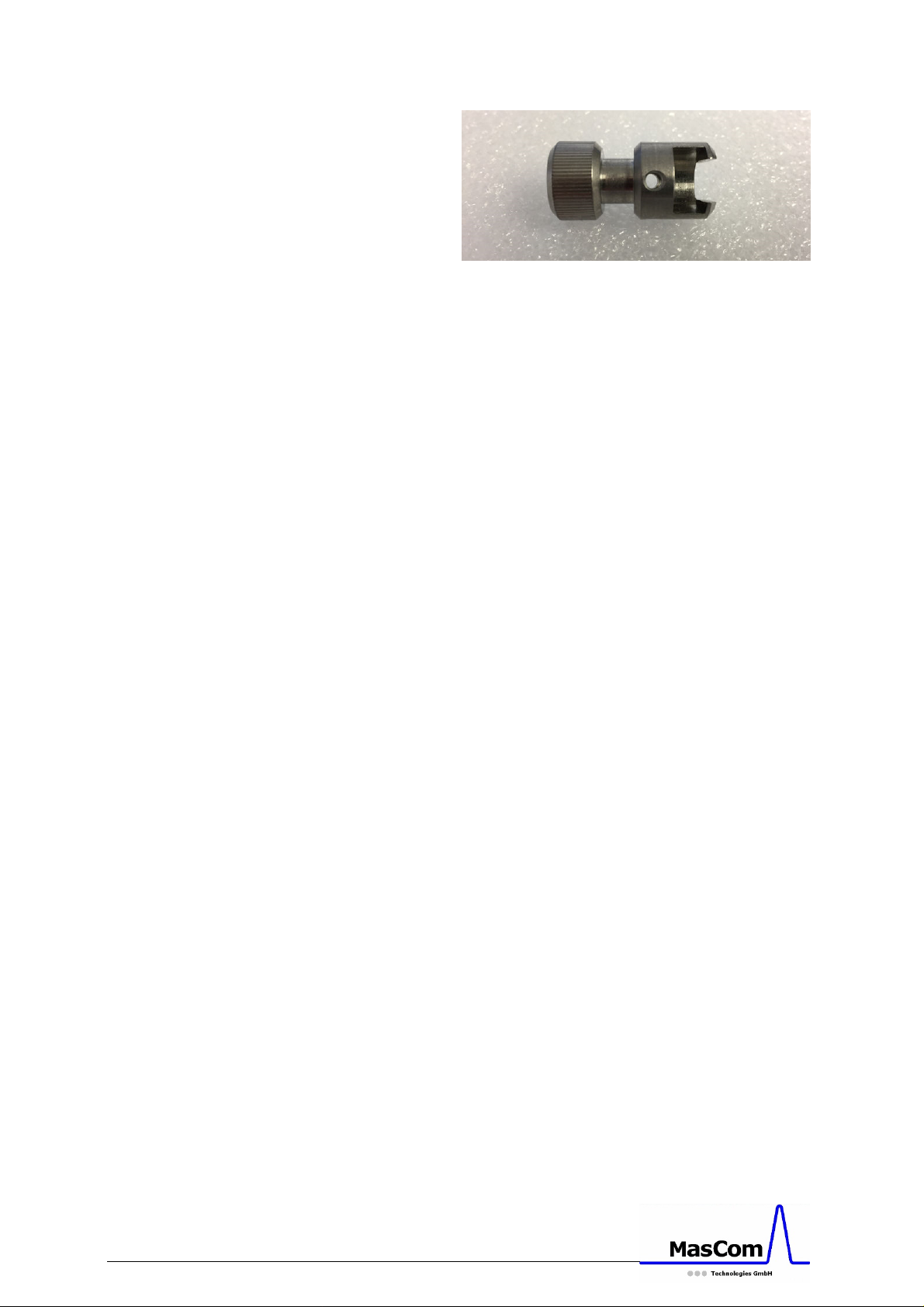
Figure D: Special tool for removing the transfer
tube on Obritrap Fusion only
Tools used for the GC column connection on the
GC injector are described in the GC manual.
GC-APPI Interface Page 5
Page 6
Installation of the GC-APPI Interface
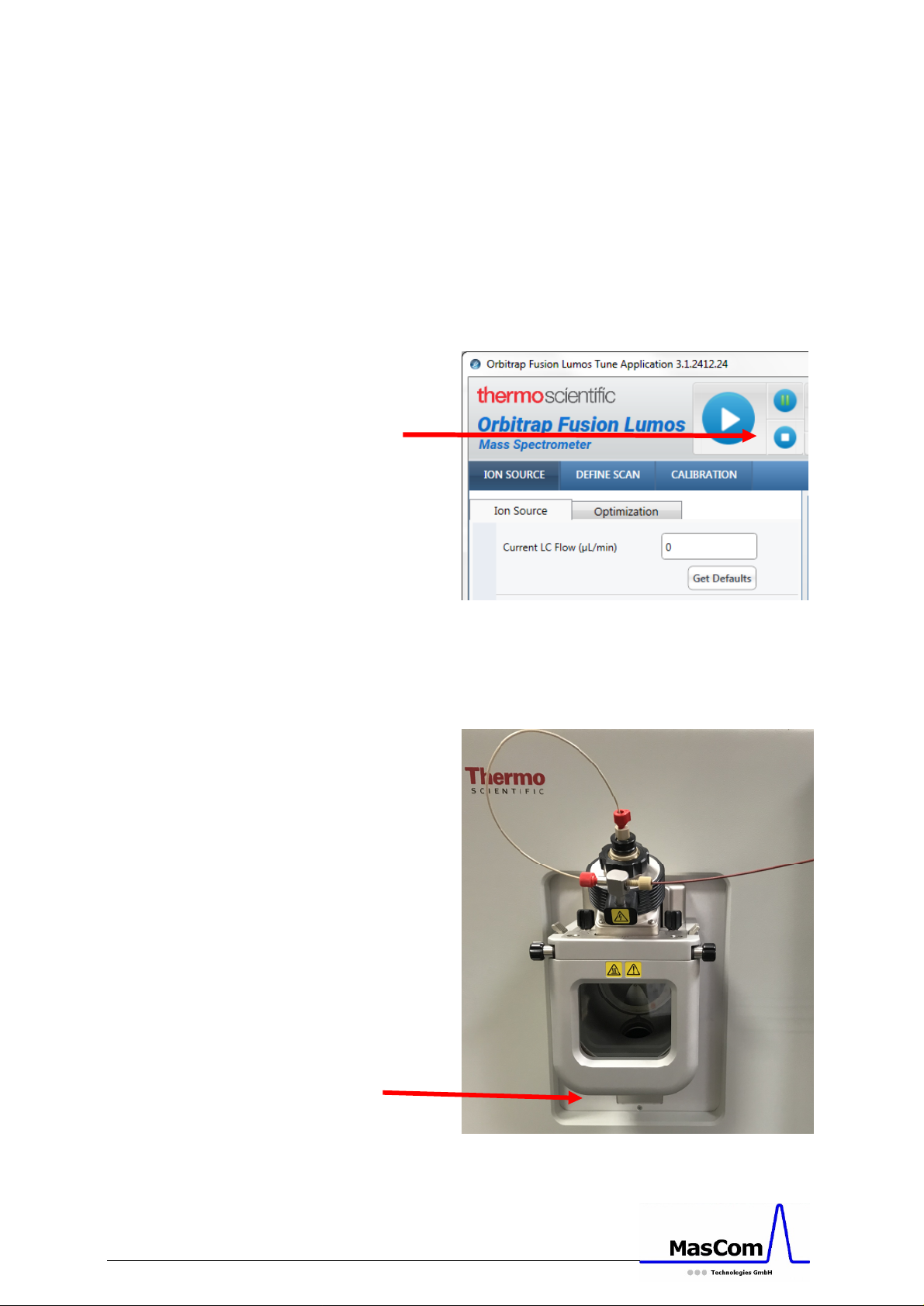
Before installing the GC-APPI-Interface you have
to remove the ESI sprayer. Make sure the mass
spectrometer is set to “Off”, and the heated ion
transfer tube is set to room temperature (see
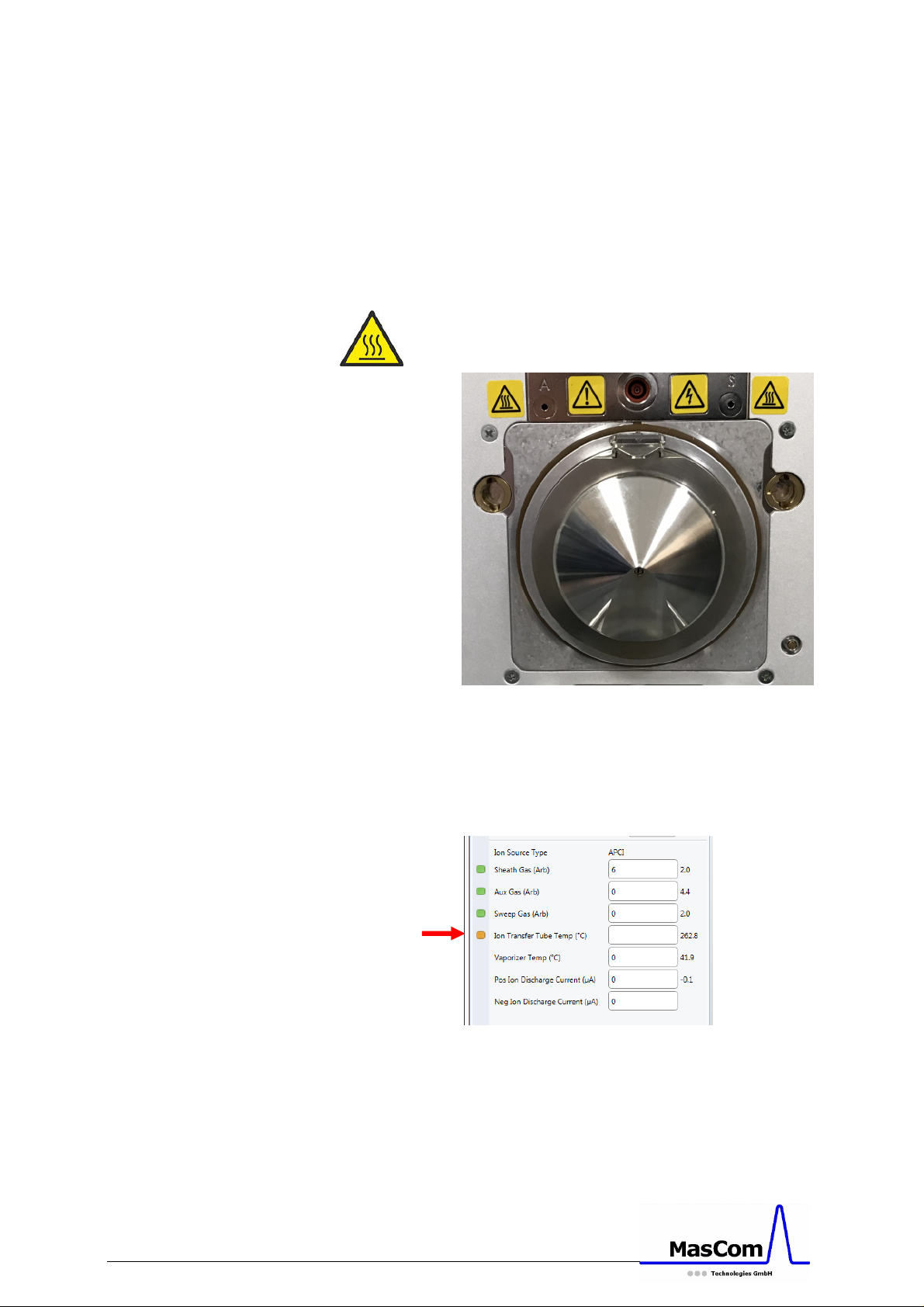
Figure 1 and 4).
Caution: Removing the ESI sprayer while the
instrument is on or in standby will load the default
Tune file and eventually start the capillary heating.
Figure 1: Instrument in “Off” mode
Disconnect the waste hose from the bottom of the
TNG source, as well as all gas, syringe, and
electrical connections.
GC-APPI Interface Page 6
Figure 2: Instrument with ESI sprayer
Page 7
Carefully remove the ESI sprayer from the mass
35
spectrometer interface and put it aside in a safe
place.
Remove the Thermo ion sweep cone as shown in
Figure 3, which is the removable spray shield that
sits just over the ion transfer tube. Using a small
flat-head screwdriver, loosen the set screws on
the sides of the spray shield.
Caution: The ion sweep cone may still be hot.
Be sure to cool down the ion transfer tube.
Figure 3: TNG source with sweep gas cone
Temperature setting is done on the TUNE page
(see Figure 4).
Figure 4: Ion transfer tube temperature setting
GC-APPI Interface Page 7
Page 8
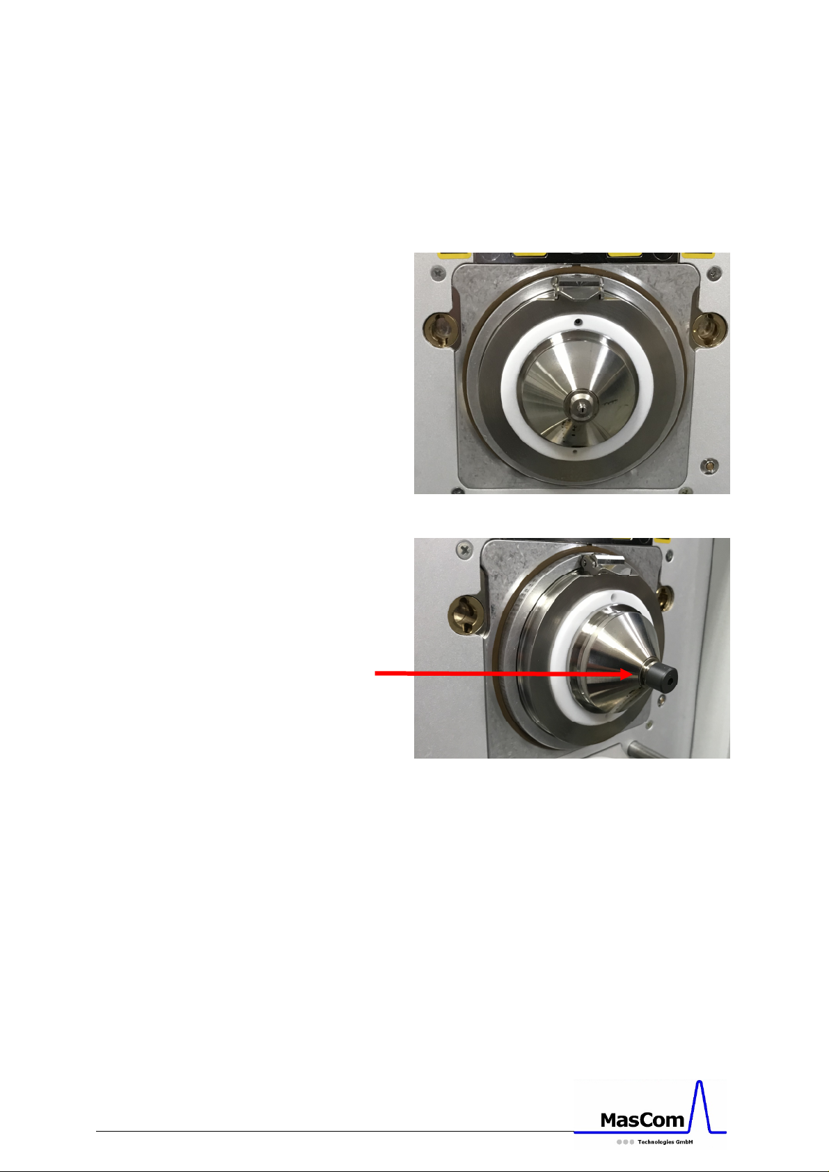
The next step (Figure 5 and 6) is for
Orbitrap Fusion Lumos only:
Place the Vespel disk (P/N: MC502620) on the
original ion transfer tube (no need to change it as
on the Orbitrap Fusion) with the rounded edge
towards the APPI-Interface (see Figure 6).
Figure 5: Ion source without sweep cone
Figure 6: Ion transfer tube with Vespel disk
The next steps (Figure 5x, 6x and 7x)
are for Orbitrap Fusion only:
After removing the ESI sprayer, you can access to
the transfer tube of the mass spectrometer.
Remove the transfer tube with the special tool
GC-APPI Interface Page 8
Page 9
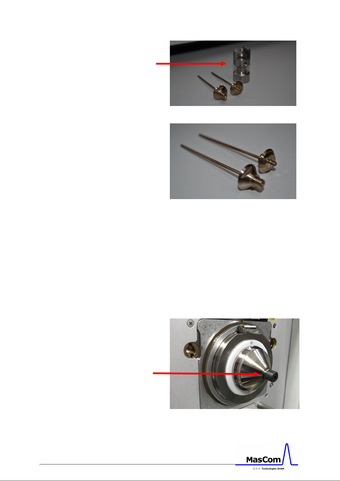
Figure 5x: Special tool for transfer tube removal
A B
Figure 6x: Standard (A) and GC-APPI (B) transfer
tubes (P/N: MC501730)
(see Figure 5x) or with the 5/16 wrench as
described in the operating manual of the mass
spectrometer.
Caution: Exchanging the transfer tubes at high
temperature is difficult and may damage them.
Replace the standard transfer tube (A) with the
GC-APPI transfer tube (B) (P/N: MC501730, see
Figure 6x,), and place the Vespel disk (P/N:
MC502610) on to the transfer tube (Figure 7x).
Make sure the disk is clean and free of dust.
GC-APPI Interface Page 9
Figure 7x: GC-APPI transfer tube with Vespel disk
Page 10
All followings steps are for both Fusion type
systems.
Bring the closed GC-APPI Interface in front of the
Mass Spectrometer and arrange the cable for the
APPI lamp close to its final position. Mount the
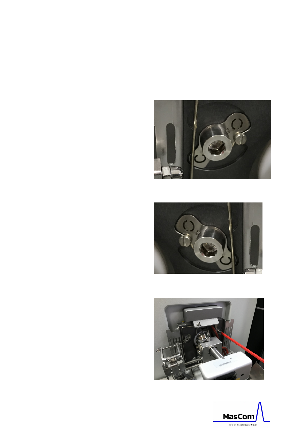
interface, open it and lock it (Figure 7a, 7b, 8a and
8b) with a 6 mm Allen wrench.
Figure 7a: Locked position of the left GC-APPIInterface connector
GC-APPI Interface Page 10
Figure 7b: Locked position of the right GC-APPIInterface connector
Figure 8a: Mounting of the GC-APPI-Interface
Page 11
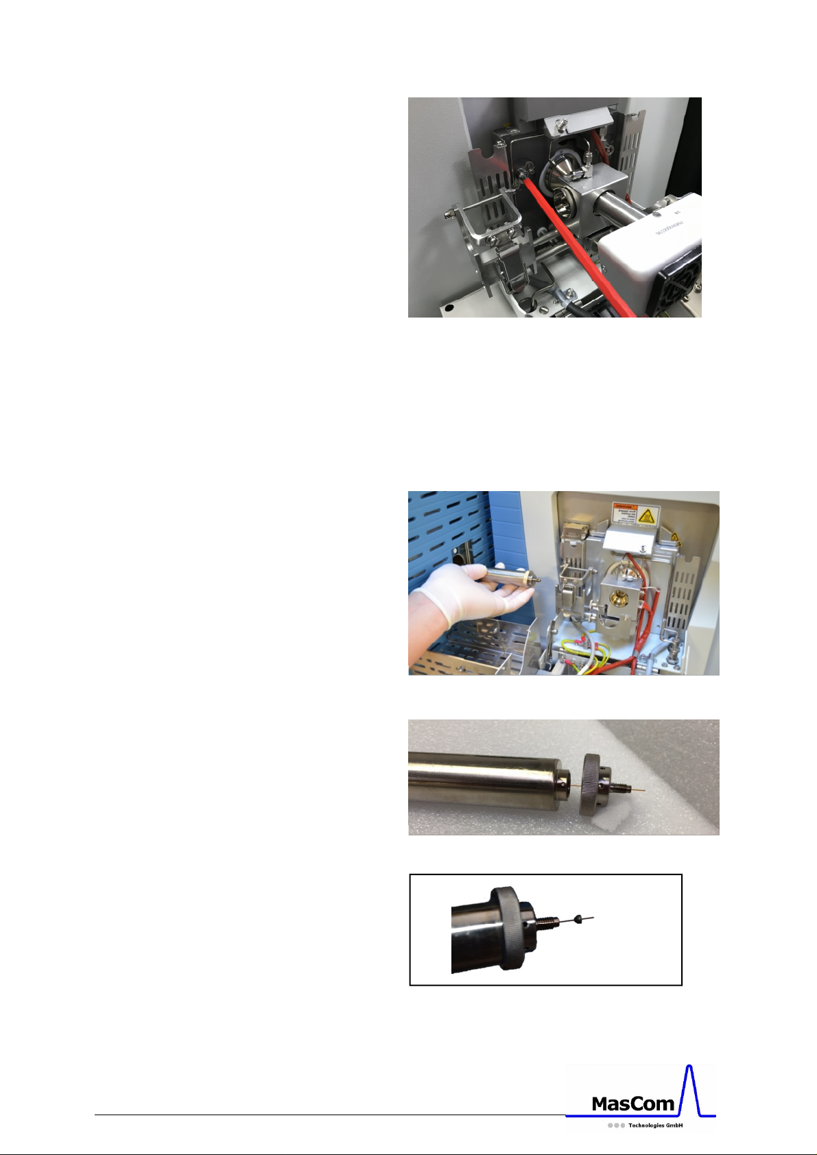
Figure 8b: Mounting of the GC-APPI-Interface
Next, attach the transfer line to the APPI-source.
Remove the APPI lamp for better access to the
transfer line connection. Place the connector in
front of the transfer line (Figure 10) and after
inserting the GC column place the graphite ferrule
with the conical side towards the transfer line.
Figure 9: Transfer line connection to APPI source
GC-APPI Interface Page 11
Figure 10: Transfer line with connector
Figure 11: Transfer line with connector and ferrule
Page 12
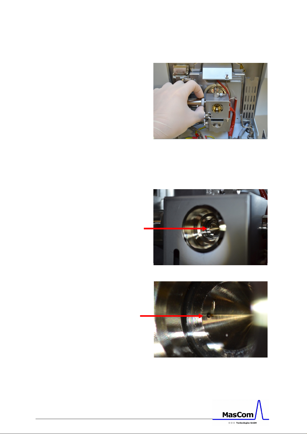
Attach the transfer line with connector and ferrule
to the APPI source and only slightly tighten the
connector (see Figure 12).
Figure 12: Transfer line connection to APPI source
Adjust the GC column before finally tighten the
connector. It just has to protrude out of the inner
source (see Figure 13a and b) by about 0.5 to 1
mm (check with a flashlight).
GC-APPI Interface Page 12
Figure 13a: GC column inside APPI source
Figure 13b: GC column inside APPI source,
zoom-in
Page 13
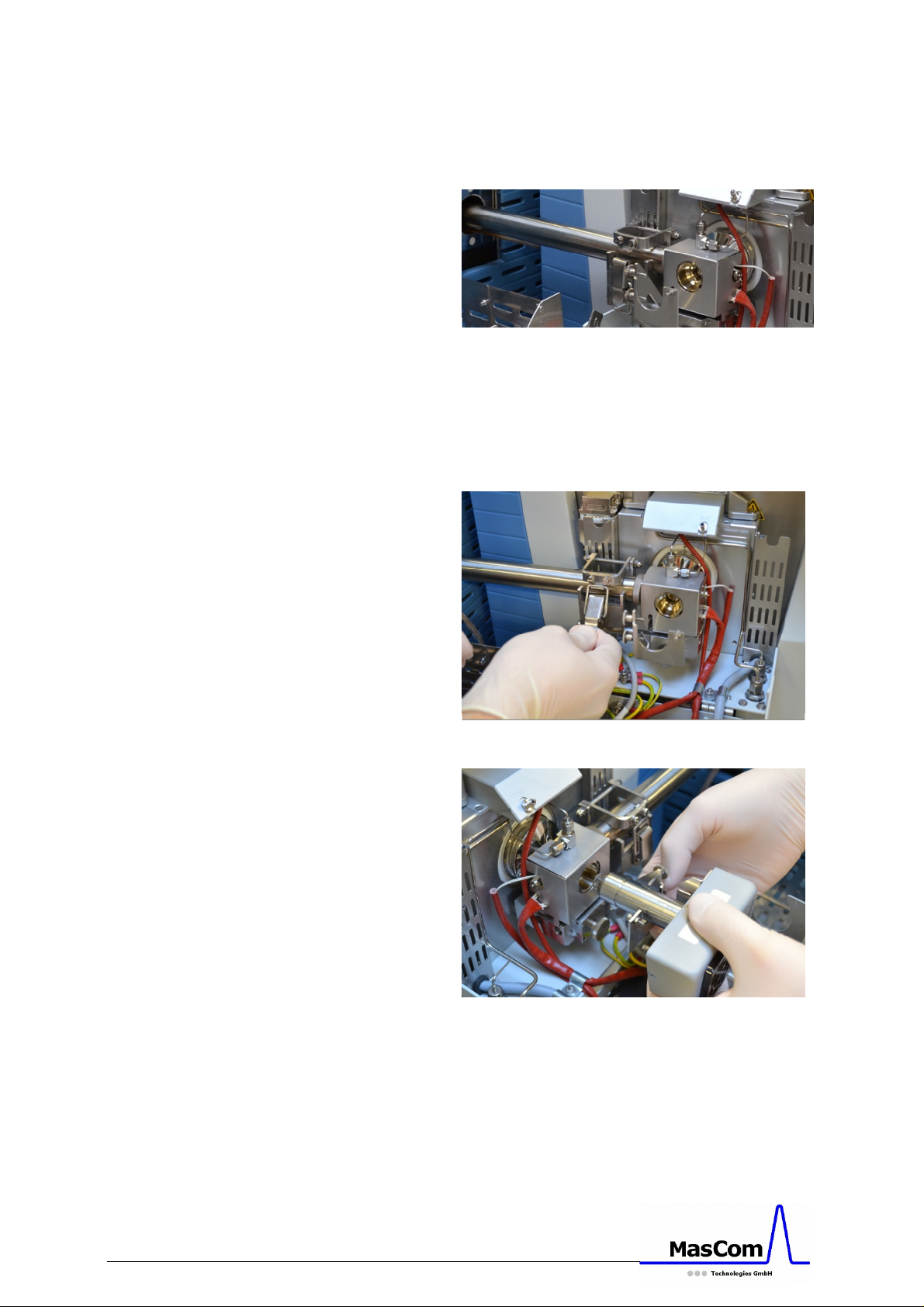
Finally tighten the transfer line connector and
press the transfer line against the connector
before fixing it with the clamp (see Figure 15).
Figure 14: Transfer line in its final position
Now insert the APPI lamp into the lamp holder
and tighten the two screws to fix the lamp in its
final position.
Figure 15: Transfer line fixing with clamp
Figure 16: Positioning of the APPI lamp
GC-APPI Interface Page 13
Page 14
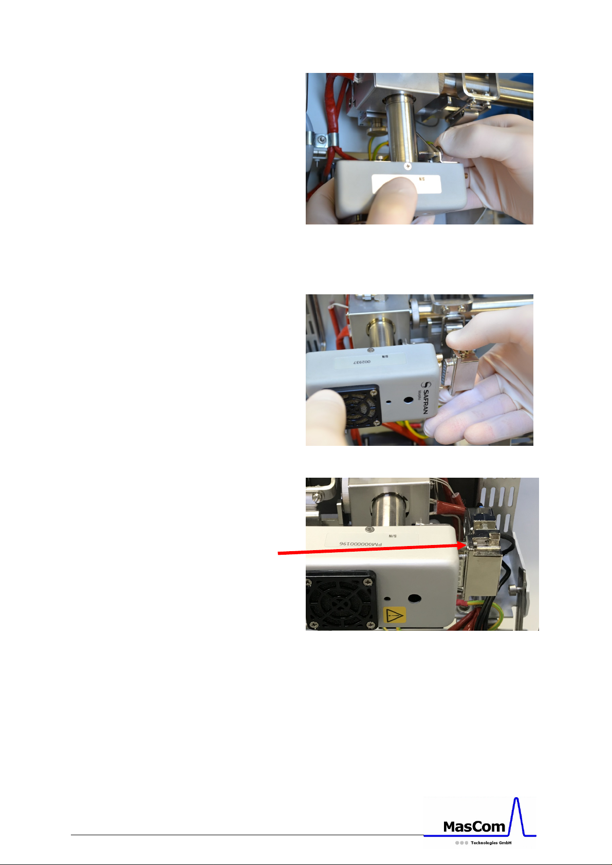
Figure 17: Fixing APPI lamp in its final position
When the lamp is inserted and fixed, connect the
cable to the lamp and fix the plug with the screws.
Figure 18: Connecting the APPI lamp cable.
GC-APPI Interface Page 14
Figure 19: Fixing APPI cable.
Close the cover of the interface and make sure the
protection shield completely covers the transfer
line.
Page 15
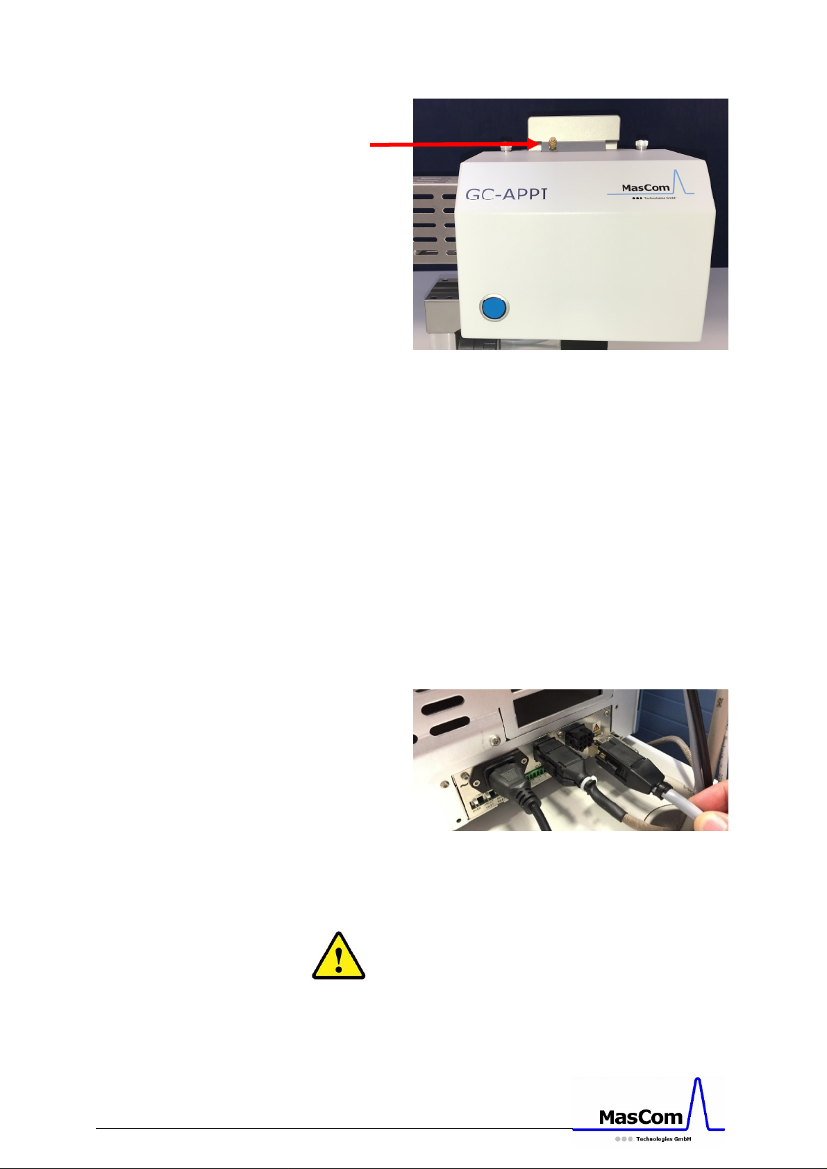
Figure 20: Closed APPI interface with dopant gas
line connected
In case you want to use an optional dopant gas,
remove the blind plug and connect the dopant gas
line as seen in Figure 20. If you do not want to use
any dopant gas, please check if the blind plug is
properly tighten.
When everything is attached to the mass
spectrometer, you can plug in the power line of
the GC-APPI interface either into the Trace 1310
GC or Trace GC Ultra.
When the power line is connected and the cover is
closed, check if the fan is running (air stream
underneath the interface).
GC-APPI Interface Page 15
Figure 21: APPI source heater connection on Trace
1310 GC
Caution: do not connect the heater cable without
the interface attached to the mass spectrometer!
Please note: when connecting the heater cable for
the first time, it will only be recognized by the GC
if the cover is closed.
Page 16
Operation of the GC-APPI Interface
Setting up the Instrument Configuration for
Thermo GC Systems
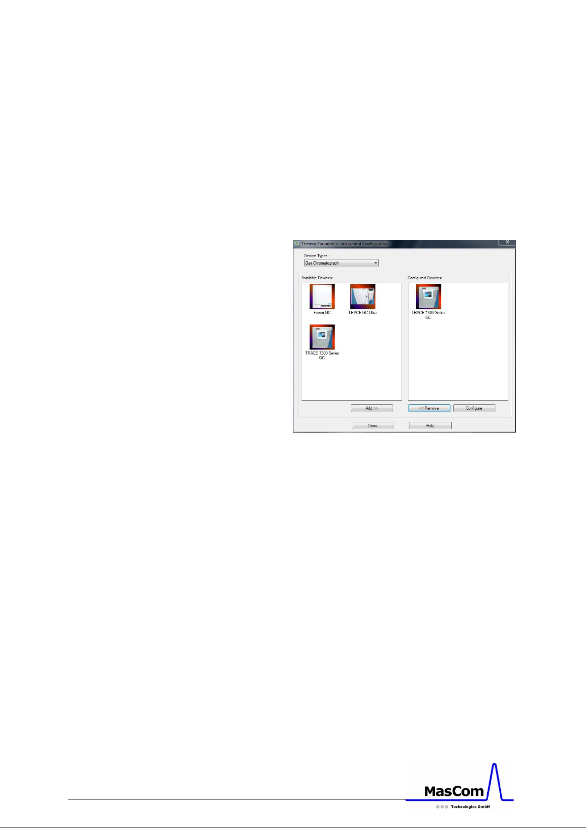
Close all Xcalibur programs and open the
Instrument Configuration. Make sure the GC
devices are installed and select the Thermo Focus,
Trace 2000, Trace Ultra or Trace 1310 GC from
the list of GC devices.
Figure 22: Xcalibur Instrument Configuration
If you are using an autosampler, please select it
from the list too. Check that the communication
of the GC (and autosampler) is correct and close
the Instrument Configuration panel.
Setting up the Instrument Configuration for
APPI Source usage
In the Instrument Configuration select the
Orbitrap Fusion and click on configure (see Figure
23).
GC-APPI Interface Page 16
Page 17
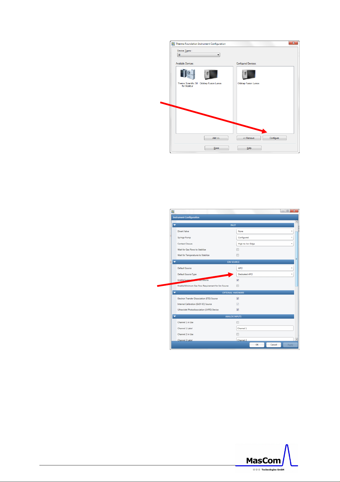
Figure 23: Xcalibur Instrument Configuration with
Orbitrap Fusion selected
Change the Default Source Type to ‘Dedicated
APCI’ and click on ‘Apply’. Leave this page with
‘OK’ (see Figure 24).
GC-APPI Interface Page 17
Figure 24: Xcalibur Instrument Configuration for
Orbitrap Fusion
Close the Instrument Configuration, start Xcalibur
and wait for all instruments to initialize and to
become “Ready for download”.
Page 18
Tune the MS
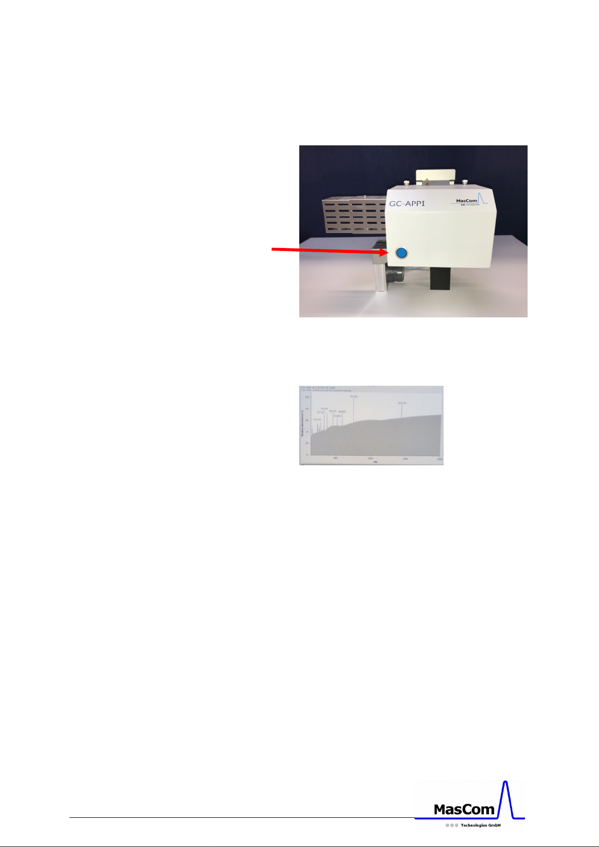
Turn on the MS and tune the mass spectrometer
in APPI mode. Make sure the APPI lamp switch is
in on position (blue LED is on, see Figure 25).
Figure 25: APPI source with lamp switch
If the APPI lamp is off, the noise level will be very
high (see Figure 26).
Figure 26: MS tune spectrum when APPI lamp is
off
When using a dopant gas you can tune the MS
using the dopant gas’ molecular ion (i.e. m/z 92
for toluene). Without a dopant gas the easiest
way to tune the MS is to select a GC column-bleed
ion like m/z 207 or similar.
Once the tuning is optimized, save the Tune file
(an example can be seen in Figure 27).
GC-APPI Interface Page 18
Page 19
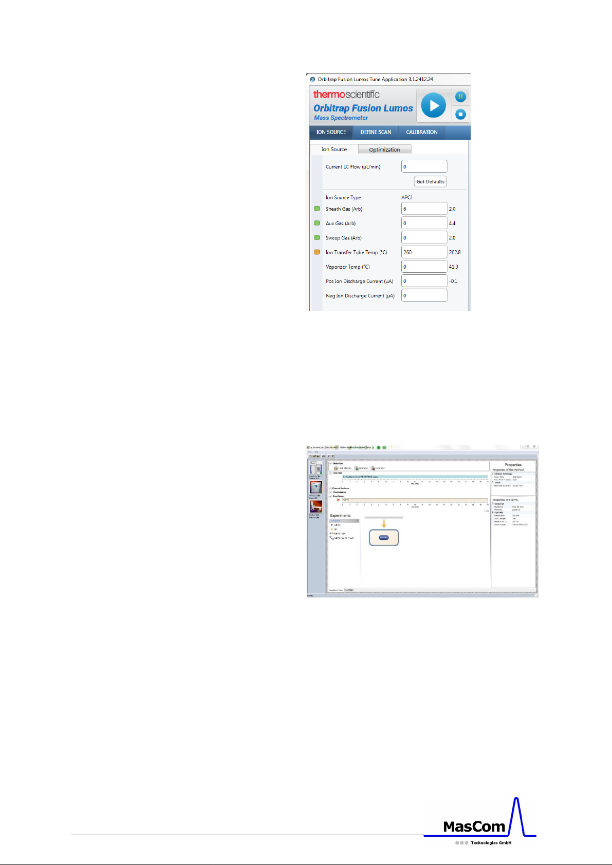
Figure 27: Example of MS tuning in APPI mode
Setup the Instrument Method
The following is valid when using the Thermo
Scientific Trace 1310 GC. For any other GC, we
refer to its dedicated manual.
GC-APPI Interface Page 19
Figure 28: Instrument Method Setup
Open the Instrument Method editor from the
Xcalibur Home page. In the editor, you will see the
different instruments.
Select the Trace 1310 GC and setup the desired GC
method. On the Aux Temperatures tab you have
to enter the temperature of the transfer line and
the temperature of the APPI source (listed as Aux.
Heater 2, see Figure 29). Both temperatures
Page 20
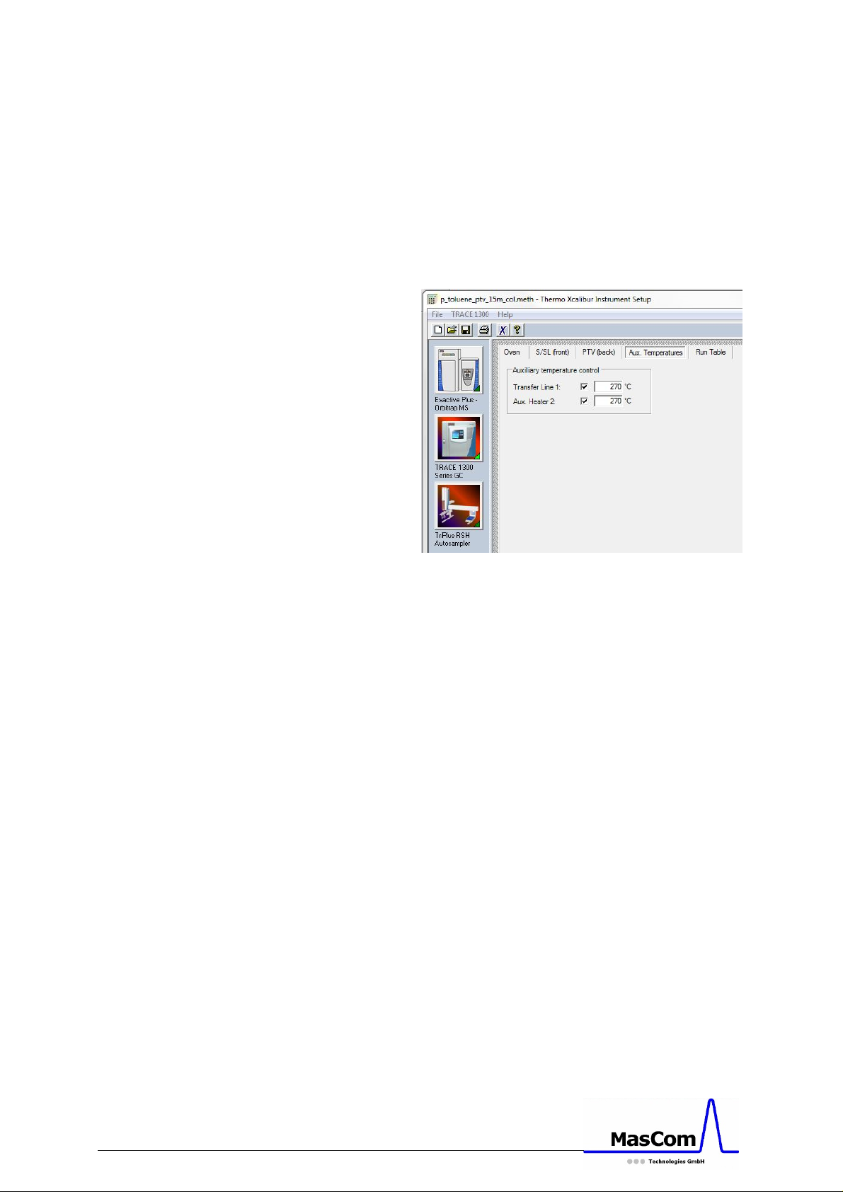
should not differ a lot from each other. Typical
temperatures are between 225 and 300 deg. C.
Please note:
The maximum temperature of the APPI source is
330 deg. C.
For details of the GC setup and/or programming,
we refer to the GC Manual.
Figure 29: Aux Temperature for Trace 1310 GC in
Instrument Method Setup
Switch to the MS to select or setup the
appropriate MS method with the corresponding
MS Tune file. If an autosampler is in use, also
setup the correct autosampler method. Save the
Instrument Method and setup a sequence file.
Setup the Sequence File
From the Xcalibur Home page, select the
Sequence editor to setup one or more sample
measurements. For details, we refer to the
standard MS operation manual.
Running a GC sample
GC-APPI Interface Page 20
When all instrument devices in Xcalibur are
“Ready for download”, you can start the sample or
sequence measurement from the sequence setup.
Page 21
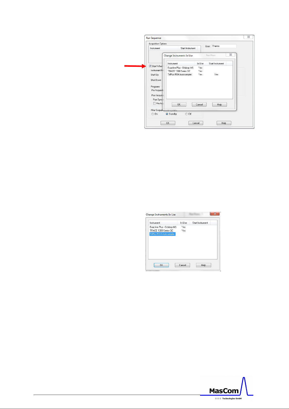
Figure 30: “Change Instruments in Use” of
Xcalibur
Once you have setup the GC and autosampler as
new devices in the instrument method, Xcalibur
will ask to “Change the Instruments in Use”.
Figure 30 shows the setup for using an
autosampler as start device. Without an
autosampler no “Start Instrument” has to be
selected, which will force the instrument devices
to wait for the contact closure (see Figure 32).
GC-APPI Interface Page 21
Figure 31: “Change Instruments in Use” without
Autosampler
After clicking on OK, the instrument method will
be downloaded into each device and when
everything is ready, the autosampler will start
with the injection. Without an autosampler the
instruments will be pending with showing the
message ‚Waiting for contact closure‘. This
contact closure will be performed when pressing
the start button on the GC after a manual sample
injection. Make sure the check box ‘Start When
Ready’ is activated (see red arrow on Figure 30).
Page 22
Final Remarks
When everything is in place and the
communication cables connected, close Xcalibur
before switching on the GC and optionally the
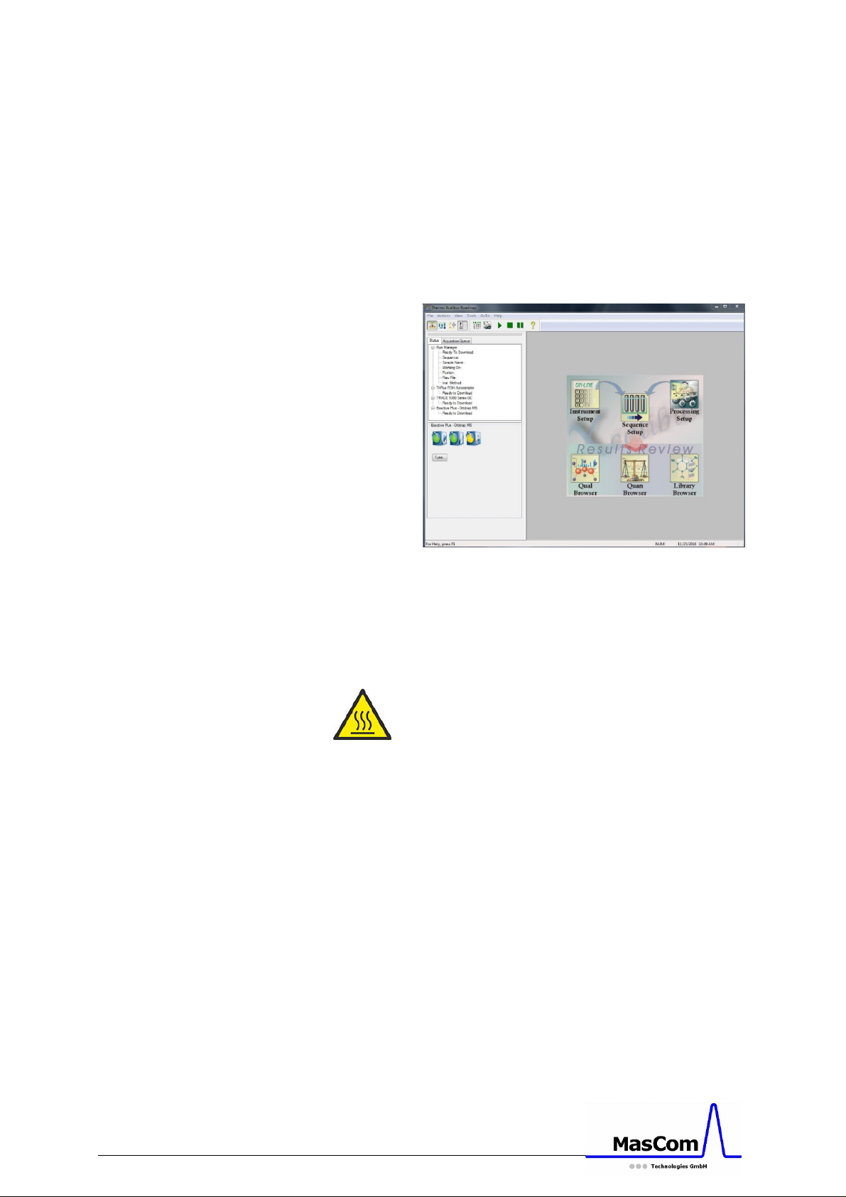
autosampler. After starting Xcalibur, all devices
will be initialized and finally “ready for download”
as shown below.
Figure 32 Xcalibur Home Page showing all devices
“Ready for Download”
Switching back to ESI operation
Before starting with the dismantling of the GCAPPI interface turn off the mass spectrometer, the
APPI lamp (turn off the blue switch on APPI source
cover shown in figure 25, and unplug the power
cable), the source heating and the transfer line
heating (unplug both cables).
Wait until everything is cooled down!
When all parts are at room temperature, you can
uninstall the GC-APPI interface and re-connect the
ESI sprayer onto the mass spectrometer. Do not
forget to mount the sweep gas cone and to
change back to ESI from APCI in the instrument
configuration of the Orbitrap Fusion (see Figure 23
and 24).
GC-APPI Interface Page 22
Page 23

Final Disposal
In case you want to finally dispose the GC-APPI
interface, you can return it to us with a
corresponding declaration of decontamination
(form can be downloaded on our web site).
GC-APPI Interface Page 23
Page 24
Troubleshooting
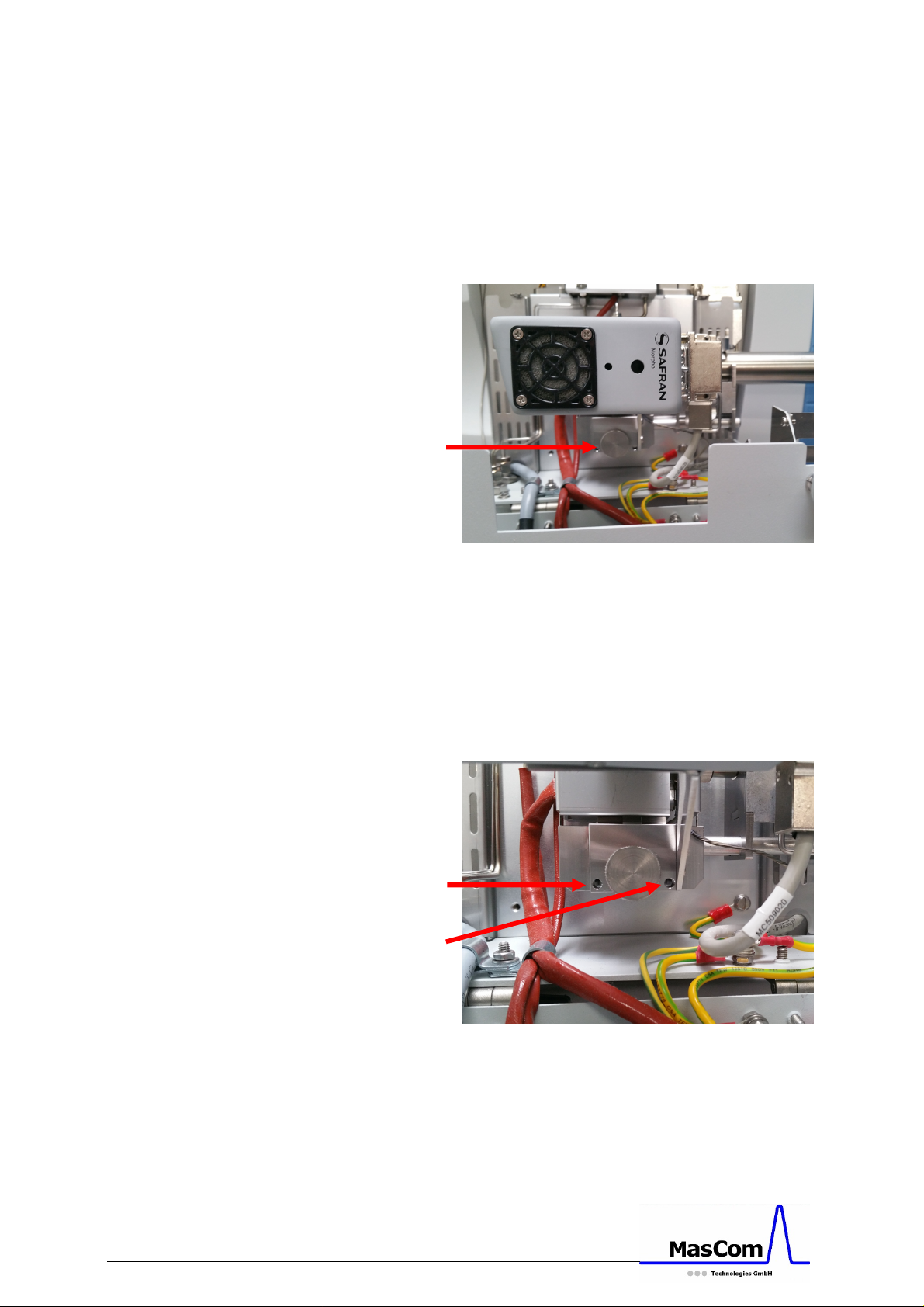
When the vacuum is not in the range of 10e-1
mBar (make sure the Vespel disk is in place, see
Figure 6), the position of the interface to the MS
might be wrong and needs to be re-adjusted.
For that, you have to loosen the knurled screw
Figure 33 Knurled screw, which fixes the interface
adjustment
(see Figure 33) and adjust the distance of the
interface with the two Allen screws (see Figure 34)
by watching the vacuum readback of the mass
spectrometer. Turning the screws out will bring
the interface closer to the MS and result in better
vacuum.
Figure 34 Allen screws for interface adjustment
GC-APPI Interface Page 24
Page 25

Graphite Ferrule for Transfer Line
Graphite Ferrule for Transfer Line
Graphite Ferrule for Transfer Line
Spare Part List
The following spare parts are available:
Part No. Description
MC502240 – MgF2 Window
MC505000 – PID-Lamp, 10.6 eV Kr
MC502610 – Vespel Disk for Orbitrap Fusion
MC502620 – Vespel Disk for Orbitrap Fusion
Lumos
MC501730 – Transfer Tube for Orbitrap Fusion
MC502350 – Gold Gasket for MgF2 Window
SG-073109 –
Connector ID 0.25 (pack of 10)
SG-073111 –
Connector ID 0.32 (pack of 10)
SG-073113 –
Connector ID 0.45 (pack of 10)
MC502450 – Filter Cartridge, Triple Filter F301
0523630S – Reducing Union 1/8"-1/16", stainl.
Steel for TX-Line, requires
exchange of stainless steel ferrule
with appropriate graphite ferrule
listed above.
GC-APPI Interface Page 25
Page 26
Optional Items for GC-APPI
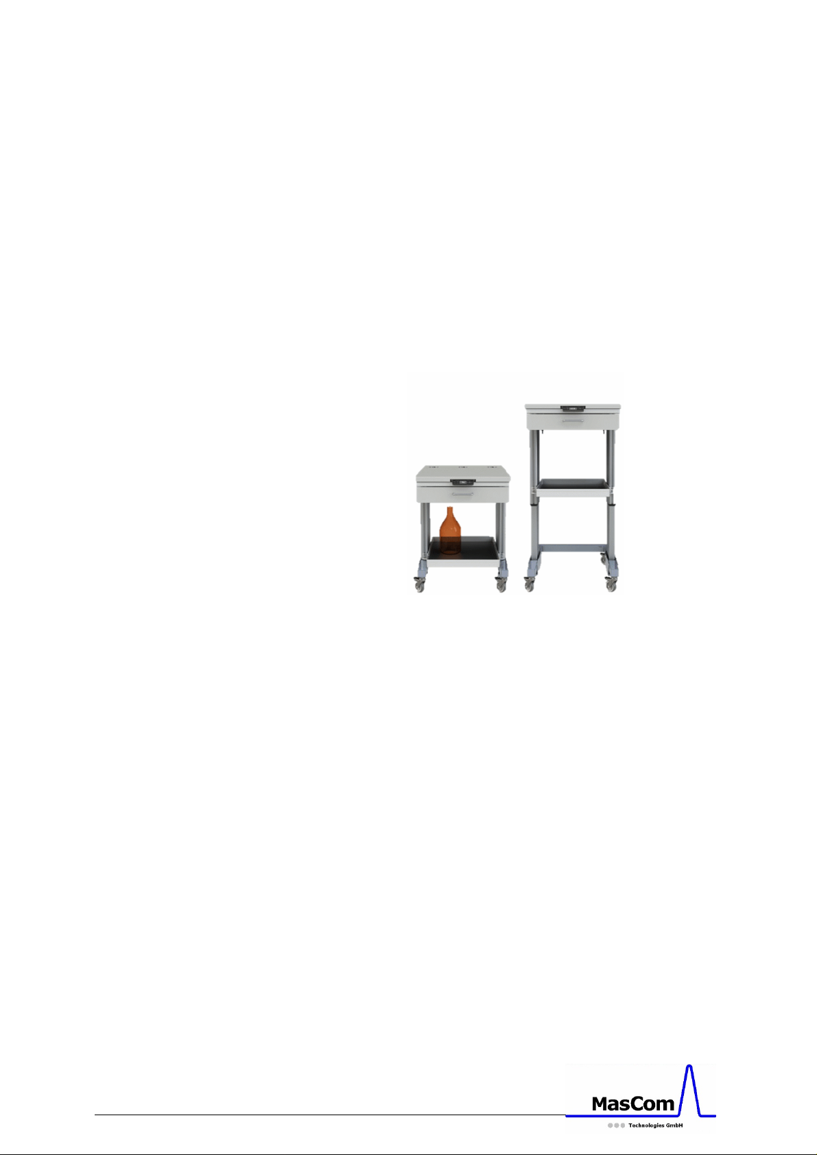
The following items are available as option:
Pneumatic Table for GC or HPLC
P/N: MC600200
- work surface size 60 x 80 cm
- lift able columns
- adjustable height from 76 to 121 cm
- integrated 3 IEC power plugs
- table on caster wheels for easy transport
GC-APPI Interface Page 26
Page 27
 Loading...