

Page 1
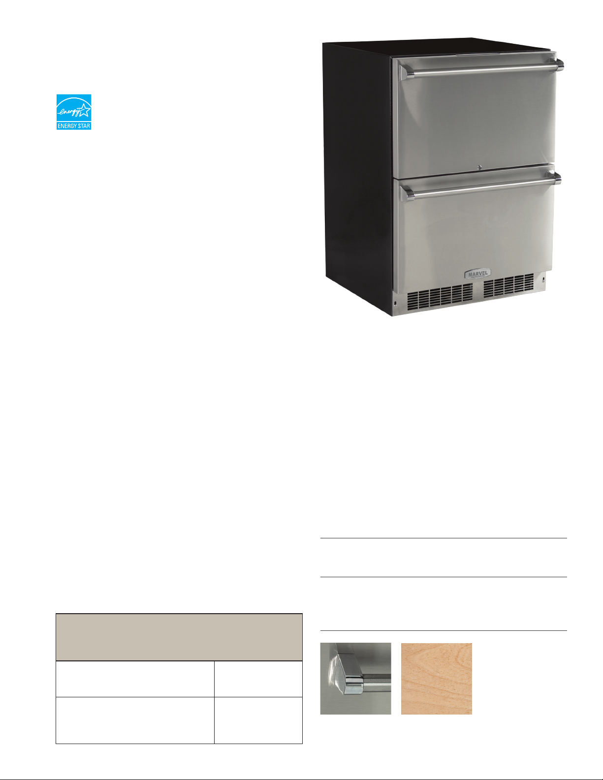
24” Marvel Professional
Refrigerated Drawers
Model # MP24RD****
Certied to meet
ENERGY STAR® requirements
• Dynamic Cooling Technology™ delivers
rapid cooldown and the industry’s best temperature stability
• Specially designed for a truly ush, zero clearance t with adjoining
cabinetry
• Door lock to protect your contents
• Professional st yling: sleek stainless steel drawers, sturdy full-length
handles and 4” adjustable stainless steel toe kick
• MARVEL Intuit™ Integrated Controls provide precise temperature
management from 34°F to 42°F
• Efcient white LED lighting
• Interior durably constructed from stainless steel, the most hygienic,
easy-to-clean and stain-resistant of materials
• Insulated thermal-ef cient cabinet and drawer fronts ensures
optimum efciency and preser vation
• Close Door Assist System™ gently and automatically closes drawers
• Audible and visual alarm signals when drawer is left ajar to protect
food integrity and energy use
• Vacation/Sabbath mode conserves energy during times when the
unit is not in use and complies with Star-K requirements
• Height adjustment up to 1” with
leveling legs
• 3-year warranty
Ordering
Details
Solid Stainless Steel Drawer Fronts,
With Lock
Solid Panel Overlay Ready Drawer
Fronts, With Lock Sold without
handles
No panel installation kit re quire d.
MP24RDS2NS
MP24RDP2NP
Storage Capacity
Up to (108) 12-oz cans
Product Dimensions
23⅞” W x 33¾” minimum H x 25⅝” D
(including handle)
Finish/Door Options
Stainless Steel Wood Overlay
(Panel Ready)
Page 2
Side
Front
Side
Forced
Air Fan
Evaporator
Plate
Return
Air Intake
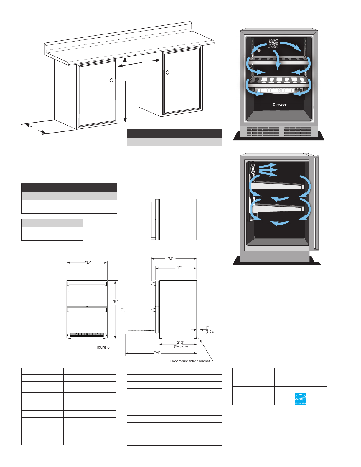
"D"
"E"
"F"
"G"
"H"
Floor mount anti-tip bracket.
PRODUCT
WEIGHT
130 lbs
(59 kg)
130 lbs
(59 kg)
21
1
⁄2"
(54.6 cm)
1"
(2.5 cm)
Figure 8
PRODUCT DIMENSIONS
"B"
"A"
"C"
Cabinet Dimensions
"D" "E" "F"
23 7⁄8”
(60.7 cm)
“G” “H”
26 7⁄32”
(66.6 cm)
33 3⁄4” to 34 3⁄4”
(85.7 to 88.3 cm)
39 5/32”
(99.5 cm)
23 23⁄ 32”
(60.2 cm)
24" Rough-In Dimensions
"A" "B" "C"
24”
(61 cm)
**34" to 35"
(86.4 to 88.9 cm)
24”
(61 cm)
Dynamic Cooling Technology™
delivers rapid cool down
and the industry’s best
temperature stability
The distinctive Marvel design features a
thermal-efcient cabinet and door combined
with Dynamic Cooling Technology™ for
superior temperature stability, faster cooling
times and speedy temperature recovery even
with high frequency.
Width 23 ⅞"
Interior Finish Stainless Steel
Capacity Up to 108 12-oz cans
Shelving System NA
Shelf Fronts NA
Other Storage
Interior Lighting 1 LED Pod per drawer
Toe Grill Finish Stainless Steel
Hinge Soft Cl ose Int egrated Hinge
Handle Professional
Control Type Intui t™
Temperature Range 34° - 42° F
Lock Yes
Electrical Requirements 120V / 60Hz / 15A
Length of Power Cord 5'
Product Dimensions 23⅞" W x 33 ¾" H x 21 ½" D
Depth to Front of Door 23
Depth to Handle 26
Depth with door at 90° 46
Shipping Weight 160 lbs
Finishes SS, O
Vacation /
Sabbath Mode
Agency Approvals CSA
Energ y Star Ce rtied
23
/32"
7
/32"
13
/32"
Finishes Key
SS = Stainless Steel
Yes
O = Overlay
Page 3
Overlay Panels
Step 3: Attach the Overlay Panel to the Drawer
1. Set the overlay panel on drawer front face and align
Step 3: Attach the Overlay Panel to the Drawer
1. Set the overlay panel on drawer front face and align
edges. (See Figure 15). The custom overlay panel
should be ush with the top of the drawer and centered
on the width of the drawer. Clamp panel in position and
mark pilot hole locations. Pick the required pilot hole
size from "Table B" below and drill the pilot holes ensur-
ing not to drill all the way through the overlay panel.
Table B: Pilot Hole Drill Sizes for Wood Screws
Material Type #8 Wood Screw
Hardwood
1
⁄8 Diameter Pilot Hole
Softwood
7
⁄64 Diameter Pilot Hole
2. Insert wood screws through clearance holes and
tighten to secure overlay panel.
3. Reinstall gasket into channel. Make sure the corners
are fully inserted.
Step 2: Size the Overlay Panel
Figure 13
.35/.31
(9 mm/7.5 mm)
.50
(12.5)
Step 4: Install the Lock
Two (2) lock extensions are provided with the lock. Use the
longer extension for 3⁄4" thick overlay panels and the shorter
one for 5⁄8" thick overlay panels. Assemble the lock exten-
sion, cam stop washer, spring washer, and set screw to the
lock as shown in Figure 16 and 17.
OVERLAY DRAWER PANEL INSTALLATION
Step 3: Attach the Overlay Panel to the Drawer
1. Set the overlay panel on drawer front face and align
edges. (See Figure 15). The custom overlay panel
should be ush with the top of the drawer and centered
on the width of the drawer. Clamp panel in position and
mark pilot hole locations. Pick the required pilot hole
size from "Table B" below and drill the pilot holes ensur-
ing not to drill all the way through the overlay panel.
Table B: Pilot Hole Drill Sizes for Wood Screws
Material Type #8 Wood Screw
Hardwood
1
⁄8 Diameter Pilot Hole
Softwood
7
⁄64 Diameter Pilot Hole
2. Insert wood screws through clearance holes and
tighten to secure overlay panel.
3. Reinstall gasket into channel. Make sure the corners
are fully inserted.
1"(25 mm) diameter counter
Figure 13
.35/.31
(9 mm/7.5 mm)
.50
(12.5)
Step 4: Install the Lock
Two (2) lock extensions are provided with the lock. Use the
longer extension for
3
⁄4" thick overlay panels and the shorter
one for
5
⁄8" thick overlay panels. Assemble the lock exten-
sion, cam stop washer, spring washer, and set screw to the
lock as shown in Figure 16 and 17.
Install this lock assembly into the lock hole in the overlay
panel and secure with the retaining nut on the back side
with a 15 mm socket and ratchet. Make sure the key slot in
the front of the lock is vertical.
OVERLAY DRAWER PANEL INSTALLATION
Screw clearance
OVERLAY DRAWER PANEL INSTALLATION
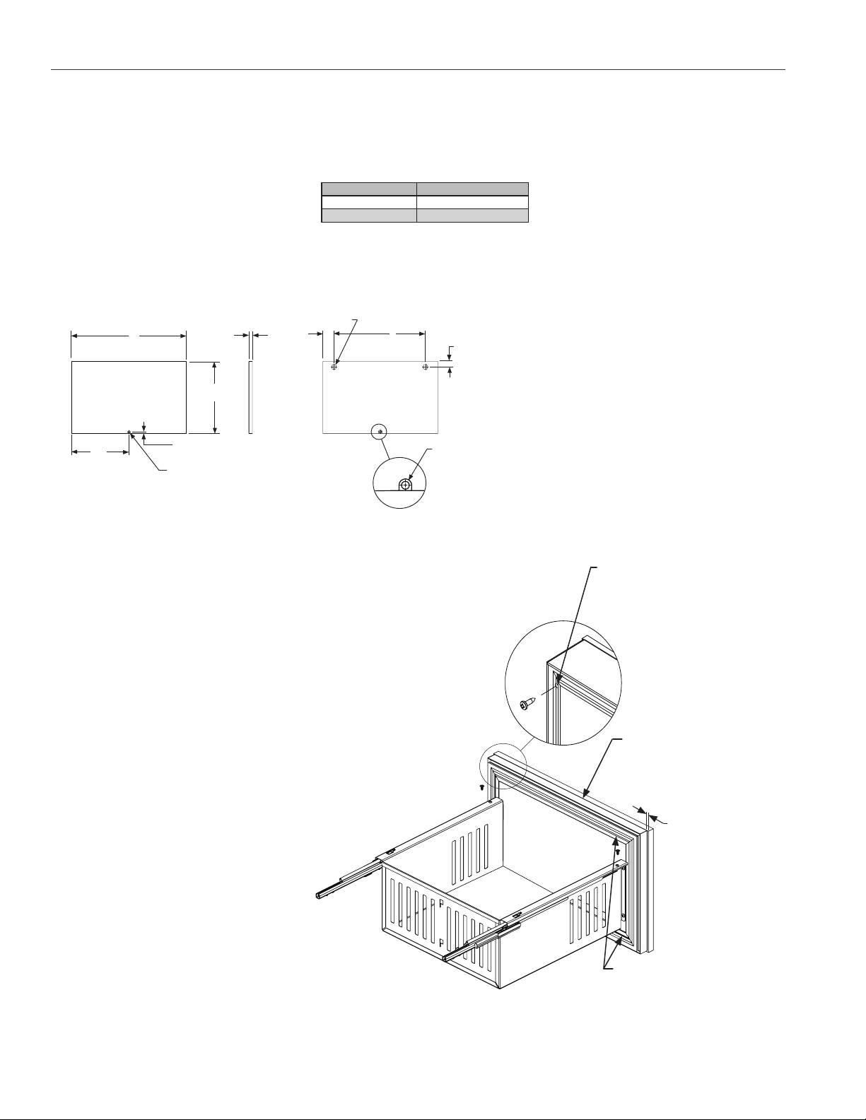
Cut the overlay panel to the dimensions shown below in
Figure 14. On the top drawer only, drill the 2 counter-bored
holes which are clearance for screw heads on the face of
the top drawer and the lock hole at the bottom of the top
drawer only.
This is also a convenient time to locate and drill the holes
for your handle. Most often the handle is to match that of
the surrounding cabinetry. If your handle attaches from the
back-side of the custom panel, locate the mounting holes
while the panel is attached to the drawer and cabinet. After
the panel is removed from the drawer, drill the mounting
holes from the front, to the recommended diameter of the
handle manufacturer. Counter bore the back-side of the
panel so the screw heads do not interfere with the surface
of the drawer.
2 places, top drawer only.
Figure 14
117⁄8"
(302 mm)
3
⁄4"
23
(603 mm)
11
⁄32"
(8.8 mm)
1
⁄2" (12.7 mm)
diameter, top
drawer only
Panel
thickness
1429⁄32"
(379 mm)
edges. (See Figure 15). The custom overlay panel
should be ush with the top of the drawer and centered
on the width of the drawer. Clamp panel in position and
mark pilot hole locations. Pick the required pilot hole
size from "Table B" below and drill the pilot holes ensuring not to drill all the way through the overlay panel.
Table B: Pilot Hole Drill Sizes for Wood Screws
Material Type #8 Wood Screw
Hardwood
Softwood
2. Insert wood screws through clearance holes and
tighten to secure overlay panel.
3. Reinstall gasket into channel. Make sure the corners
are fully inserted.
bore 1⁄4" (6 mm) deep
23⁄8"
(60 mm)
(483 mm)
This side
facing interior
1
⁄8 Diameter Pilot Hole
7
⁄64 Diameter Pilot Hole
19"
3
⁄16"
1
(30 mm)
13
⁄16" (21 mm)
counterbore
7
⁄16" (12 mm)
deep, top
drawer only
Figure 15
hole through
gasket extrusion
Figure 15a
Overlay panel
ush with top
edge of drawer
Custom overlay
panel to be centered on width of
drawer.
Using clearance holes in
gasket channel mark
hole locations onto panel
For comprehensive installation instructions,
please visit www.marvelrefrigeration.com
 Loading...