

Page 1

Installation
Operation
and
Maintenance
Instructions
Beverage and Wine
Refrigerators
MARVEL
Chateau Collection
3SBARE
6SBARE
8SBARE
Page 2

TABLE OF CONTENTS
Unpacking your beverage refrigerator....................
Removing the packaging......................
Warranty Registration .....................
Installing your beverage refrigerator.........
Selecting the location..........................
Cabinet Clearances ..........................................
Leveling legs .....................................
Grounding method..............................
Electrical Requirements........................
Using Your Sentry System™ Control ................................4
Dimensions for 3SBARE glass door.................
Recommended Rough in Opening Dimensions
for 3SBARE glass door.......................
Dimensions for 3SBARE glass overlay door.
Recommended Rough in Opening Dimensions
for 3SBARE glass overlay door........
Dimensions for 3SBARE solid overlay door.......
Recommended Rough in Opening Dimensions
for 3SBARE solid overlay door.......................................7
Dimensions for 6SBARE glass door...................................8
Recommended Rough in Opening Dimensions
for 6SBARE glass door......
Dimensions for 6SBARE glass overlay door.......................9
Recommended Rough in Opening Dimensions
for 6SBARE glass overlay door......................................9
Dimensions for 6SBARE solid overlay door
Recommended Rough in Opening Dimensions
for 6SBARE solid overlay door..........................
Dimensions for 8SBARE glass door..........
Recommended Rough in Opening Dimensions
for 8SBARE glass door......................................
Dimensions for 8SBARE glass overlay door.......................12
Recommended Rough in Opening Dimensions
for 8SBARE glass overlay door......................................12
Full Overlay Panel Installation Instructions....
Features ........................................................................16
Care and Cleaning ................................
Cleaning condenser air flow.........................
Cleaning the cabinet...................................................17
Cleaning the interior......................................
Cleaning the wine shelves.............................
Cleaning the door gasket..............................
Removing the shelves.....................................
Replacing the light tubes............................................
Troubleshooting Guide.........................
Obtaining Service ..............................
Household Product Warranty................
...............
......................
............
.....................
......................
......................
..........
...........
.........................
....................
..........................
..........................
.....
...........
.....
.................
....................
.........................
........................
.........
2
.2
.................2
..3
..3
.........
.3
...3
..............3
.............3
..............
...............
................ .10
.......
..............11
.............13
............
...........
............
............
............
...5
.5
.6
...6
7
...8
....
..10
...........11
....
..17
...17
...17
..17
..17
.17
.18
......19
..20
...21
1
Page 3

UNPACKING YOUR BEVERAGE REFRIGERATOR
NOTE
Important Safety Instructions
Warnings and safety instructions appearing in this
guide are not meant to cover all possible conditions and situations that may occur. Common sense,
caution, and care must be exercised when installing,
maintaining, or operating this appliance.
Recognize Safety Symbols,
Words, and Labels.
CAUTION-Hazards or unsafe practices which could
result in personal injury or property or product damage.
WARNING-Hazards or unsafe practices which could
result in personal injury.
Note to Customer
This merchandise was carefully packed and thoroughly
inspected before leaving our plant. Responsibility for its safe
delivery was assumed by the retailer upon acceptance of the
shipment. Claims for loss or damage sustained in transit
must be made to the retailer.
DO NOT RETURN DAMAGED MERCHANDISE TO THE
MANUFACTURER - FILE THE CLAIM WITH THE RETAILER.
If the unit was shipped or has been laying on its back for
any period of time allow the refrigerator to sit upright for a
period of at least 24 hours before plugging in. This will assure oil returns to the compressor. Plugging the refrigerator
in immediately may cause damage to internal parts.
Warranty Registration
It is important you send in your warranty registration card immediately after taking delivery of your refrigerator or you can
register online at www.marvelrefrigeration.com.
NOTE-Important information to make a problem free
installation.
Remove Packaging
Your beverage refrigerator has been packed for shipment with all parts that could be damaged by movement securely fastened. Cut the banding material at the
bottom of the carton, unfold the cartoning at the bottom
and remove the carton from the appliance. Remove the
plastic bag, styrofoam corner posts and any tape holding
the door closed and internal components in place.
The owners manual is shipped inside the beverage refrigerator in a plastic bag along with the warranty registration card.
Important
Keep your carton packaging until your beverage refrigerator has been thoroughly inspected and found to be
in good condition. If there is damage, the packaging
will be needed as proof of damage in transit. Afterwards
please dispose of all items responsibly in particular the
plastic bags which can be a suffocation hazard.
The following information will be required when registering
your unit.
Model Number
Serial Number
Date of Purchase
Dealers name and address
The model number and serial number can be found on the
serial plate which is located inside the refrigerator on the left
side toward the top of the liner.
Help Prevent Tragedies
Child entrapment and suffocation are not problems of the
past. Junked or abandoned refrigerators are still dangerous, even if they sit out for “just a few days”.
If you are getting rid of your old refrigerator, please follow
the instructions below to help prevent accidents.
Before you throw away your old refrigerator or freezer:
Take off the doors or remove the drawers.•
Leave the shelves in place so children may not easily •
climb inside.
2
Page 4

INSTALLING YOUR BEVERAGE REFRIGERATOR
Select Location
The proper location will ensure peak performance of your
appliance. We recommend a location where the unit will
be out of direct sunlight and away from heat sources. To
assure your product performs to specifications the recommended installation location temperature range is from
65 to 80°F (18 to 27°C) for indoor built in units and 65 to
90°F (18 to 32°C) for indoor freestanding units.
Cabinet Clearance
Ventilation is required from the bottom front section of the
unit. Keep this area open and clear of any obstructions.
Adjacent cabinets and counter top can be installed around
the unit as long as the grille and door access remain unobstructed.
Front Grille
Do not obstruct the front grille. The openings within the
front grille provide air to flow into and exit from the refrigerator condenser. For this reason it is important this area to
not be obstructed and be kept clean. Marvel does not recommend the use of custom made grilles as air flow may be
restricted because of inadequate openings. (See Figure 1).
Leveling Legs
Adjustable legs at the front and rear corners of the unit
should be set so the unit is firmly positioned on the floor
and level from side to side and front to back. Turn leveling
legs clockwise to raise unit, counterclockwise to lower it.
(See Figure 1).
Do not splash or spray water from a hose on the •
refrigerator. Doing so may cause an electrical shock,
which may result in severe injury or death.
This unit should not, under any circumstances, be •
ungrounded.
Grounding Method
This product is factory equipped with a power supply cord
that has a three-pronged, grounded plug. It must be
plugged into a mating grounding type receptacle in accordance with the National Electrical Code and applicable local codes and ordinances (see Figure 2). If the circuit does
not have a grounding type receptacle, it is the responsibility
and obligation of the customer to exchange the existing
receptacle in accordance with the National Electrical Code
and applicable local codes and ordinances. The third
ground prong should not, under any circumstances, be cut
or removed.
Electrical Connection
115 volts, 3.3 amps running max. 15 amp dedicated circuit
required. 3 prong grounded receptacle required.
Do not use an extension cord
with this appliance.
Front Grille,
keep this
area open.
Figure 1
Leveling Legs
3
Figure 2
Page 5

Glass Door
Model
Figure 3
Solid Door
Model
Figure 4
USING YOUR Sentry System™ CONTROL
LED
LED
Start Your Appliance
Please observe the following options when starting your
appliance during initial plug-in.
1) If Sentry System™ LED is flashing amber (see Figure 3
or 4) the appliance is on. Simply press and release “ON/
OFF” button to stop the flashing LED.
2) If the interior light is working but Sentry System™ display
is blank push and hold “ON/OFF” button for five (5)
seconds to start the appliance.
Once loaded allow at least 48 hours for the unit to stabilize
before making any adjustments to the initial temperature
setting.
Set Your Temperature Mode
This product can display either Fahrenheit or Celsius. To
do so, press the “°F/C” button on the display panel.
Viewing and Changing Current Temperature Settings
The temperature set point is initially set in the factory at 55
degrees F. The available temperature range of the unit is
from 40 to 65 degrees F (4 to 18 °C). .
To view the set point push the “SET” button once and the
word “SET” and the current set-point will be displayed.
While “SET” icon is displayed push the “WARMER” or
“COLDER” button for your desired temperature. Push the
“SET” key to exit set-point mode and activate your new
temperature settings, or after 10 seconds the new settings
will automatically be activated.
As with any refrigeration product, there is a slight temperature variance at different locations within the cabinet.
Door Ajar Alarm
If the door has been left open for over five (5) minutes, the
alarm will sound and the LED will flash green. This will
stop as soon as the door is closed.
High and Low Temperature
If your unit reaches temperatures outside normal operating
temperatures for your set point for more than one (1) hour,
an alarm will sound and the LED will flash red. This will
warn you the contents have seen temperatures that may not
be conducive for long-term storage.
Power Failure
If your unit experiences a power failure, the LED will flash
amber until the alarm is reset.
Reset Alarms
Press the “ON/OFF” button for approximately one (1) second. This will reset all audible and display alarms.
Sabbath Mode
Your refrigerator is equipped with a Sabbath Mode feature.
By activating this mode, you will be disabling all displays,
audible alarms and lights.
To activate Sabbath Mode, press and hold the “SET” button while pressing the “°F/C” button four (4) times within
seven (7) seconds. To deactivate Sabbath Mode, repeat the
process. Sabbath Mode will automatically deactivate after
72 hours.
Interior Light and Switch
The interior light makes it easy to view the contents of your
refrigerator. Pressing the “LIGHT” key toggles between 2
modes of operation for the internal lights: functional (default) mode and showcase mode. If you are in functional
(default) mode, the lights will turn on only if the door is
open. If you are in showcase mode, the lights will be on
whether or not the door is open.
Warning Alarms
Your refrigerator has been fitted with a Sentry System™
refrigeration monitor. This monitor will let you know if your
refrigerator is not functioning properly for optimum storage
and will alert you in the unlikely event there is an unstable
condition.
Advanced Sentry System™ features:
Sentry System™ continually monitors critical refrigeration
system components for proper operation. If component
parameters exceed normal operation specifications, the
display will automatically flash the respective error code as
follows:
E1-Compressor fault
E2-Condenser fan motor fault
E3-Evaporator thermistor sensor fault
E4-Display thermistor sensor fault
Please call a qualified service technician if any of these
codes are displayed.
4
Page 6

DIMENSIONS FOR 3SBARE GLASS DOOR
16-9/16”
(39.52cm)
14-7/8”
(37.78cm)
34-1/4” to 34-1/2”
(87 to 87.6 cm)
37”
(93.98cm)
25-7/32
(64.06cm)
23-9/32
(59.13cm)
3” to 3-1/4”
(7.62 to 8.26cm)
21-3/16”
(53.82cm)
Rough In Opening Dimensions, for 3SBARE Glass Door
Electrical Requirements: 115 volts,
3.3 amps running max. 15 amp
dedicated circuit required. 3 prong
grounded receptacle required.
34-1/2”
(87.6 cm)
*24” (61 cm)
standard cabinet
depth
Power outlet can be located in the
back wall behind unit. Add 1” to
depth for thickness of plug, or recess
outlet 1” into the wall. Power outlet
can also be installed in adjacent
cabinetry with a cutout for routing of
power cord. Follow all local building
codes when installing electrical and
unit.
Product weight = 125 lbs. (56.8 kg.)
15” (38.1 cm)
each individual installation.
5
* Depth dimension may vary depending on
Page 7

13-29/32”
(35.33cm)
14-7/8”
(37.78cm)
DIMENSIONS FOR 3SBARE GLASS OVERLAY DOOR
36-27/32
(93.57cm)
23-1/4”
(59.06cm)
22-17/32”
(57.23cm)
34-1/4” to 34-1/2”
(87 to 87.6cm)
3” to 3-1/4”
(7.62 to 8.26cm)
21-3/16”
(53.82cm)
Rough In Opening Dimensions for 3SBARE Glass Overlay Door
Electrical Requirements: 115 volts,
3.3 amps running max. 15 amp
dedicated circuit required. 3 prong
grounded receptacle required.
34-1/2”
(87.6 cm)
*24” (61 cm)
standard cabinet
depth
Power outlet can be located in the
back wall behind unit. Add 1” to
depth for thickness of plug, or recess
outlet 1” into the wall. Power outlet
can also be installed in adjacent
cabinetry with a cutout for routing of
power cord. Follow all local building
codes when installing electrical and
unit.
Product weight = 125 lbs. (56.8 kg.)
15” (38.1 cm)
* Depth dimension may vary depending on
each individual installation.
6
Page 8

DIMENSIONS FOR 3SBARE SOLID OVERLAY DOOR
37-5/32”
(94.39cm)
13-7/8”
(35.26cm)
(59.06cm)
14-7/8”
(37.78cm)
34-1/4” to 34-1/2”
(87 to 87.6cm)
23-1/4”
22-17/32”
(57.23cm)
3” to 3-1/4”
(7.62 to 8.26cm)
21-3/16”
(53.82cm)
Rough In Opening Dimensions for 3SBARE Solid Overlay Door
Electrical Requirements: 115 volts,
3.3 amps running max. 15 amp
dedicated circuit required. 3 prong
grounded receptacle required.
34-1/2”
(87.6 cm)
*24” (61 cm)
standard cabinet
depth
Power outlet can be located in the
back wall behind unit. Add 1” to
depth for thickness of plug, or recess
outlet 1” into the wall. Power outlet
can also be installed in adjacent
cabinetry with a cutout for routing of
power cord. Follow all local building
codes when installing electrical and
unit.
Product weight = 125 lbs. (56.8 kg.)
15” (38.1 cm)
* Depth dimension may vary depending on
each individual installation.
7
Page 9
25-21/32”
(65.15cm)
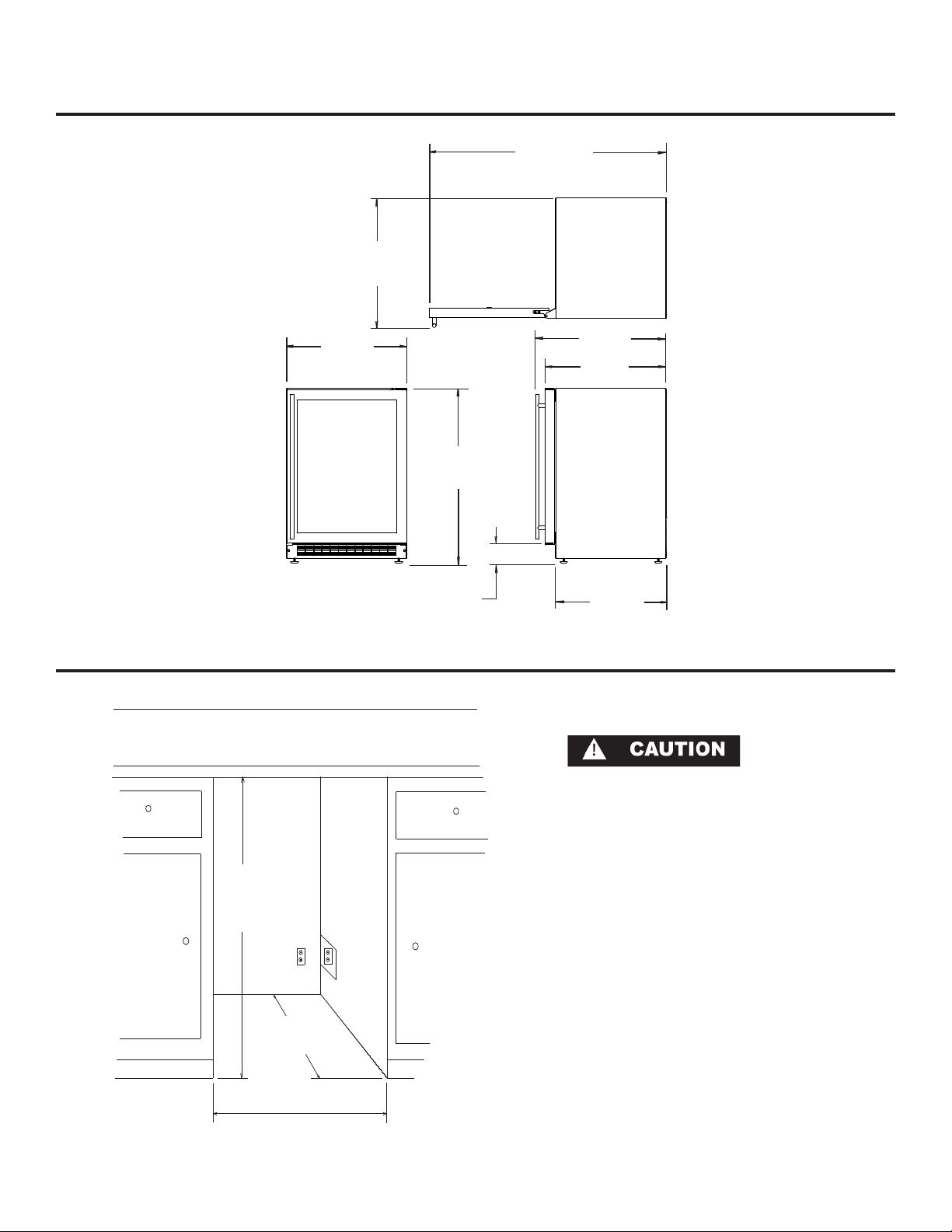
DIMENSIONS FOR 6SBARE GLASS DOOR
47”
(119.38cm)
23-7/8”
(60.66cm)
34-1/4” to 34-1/2”
(87 to 87.6cm)
3” to 3-1/4”
(7.62 to 8.26cm)
26”
(66.04cm)
24-1/16”
(61.1cm)
22”
(55.88cm)
Rough In Opening Dimensions for 6SBARE Glass Door
34-1/2”
(87.6 cm)
*24” (61 cm)
standard cabinet
24” (61 cm)
Electrical Requirements: 115 volts,
3.3 amps running max. 15 amp
dedicated circuit required. 3 prong
grounded receptacle required.
Power outlet can be located in the
back wall behind unit. Add 1” to
depth for thickness of plug, or recess
outlet 1” into the wall. Power outlet
can also be installed in adjacent
cabinetry with a cutout for routing of
power cord. Follow all local building
codes when installing electrical and
unit.
Product weight = 160 lbs. (72.7 kg.)
depth
* Depth dimension may vary depending on
each individual installation.
8
Page 10
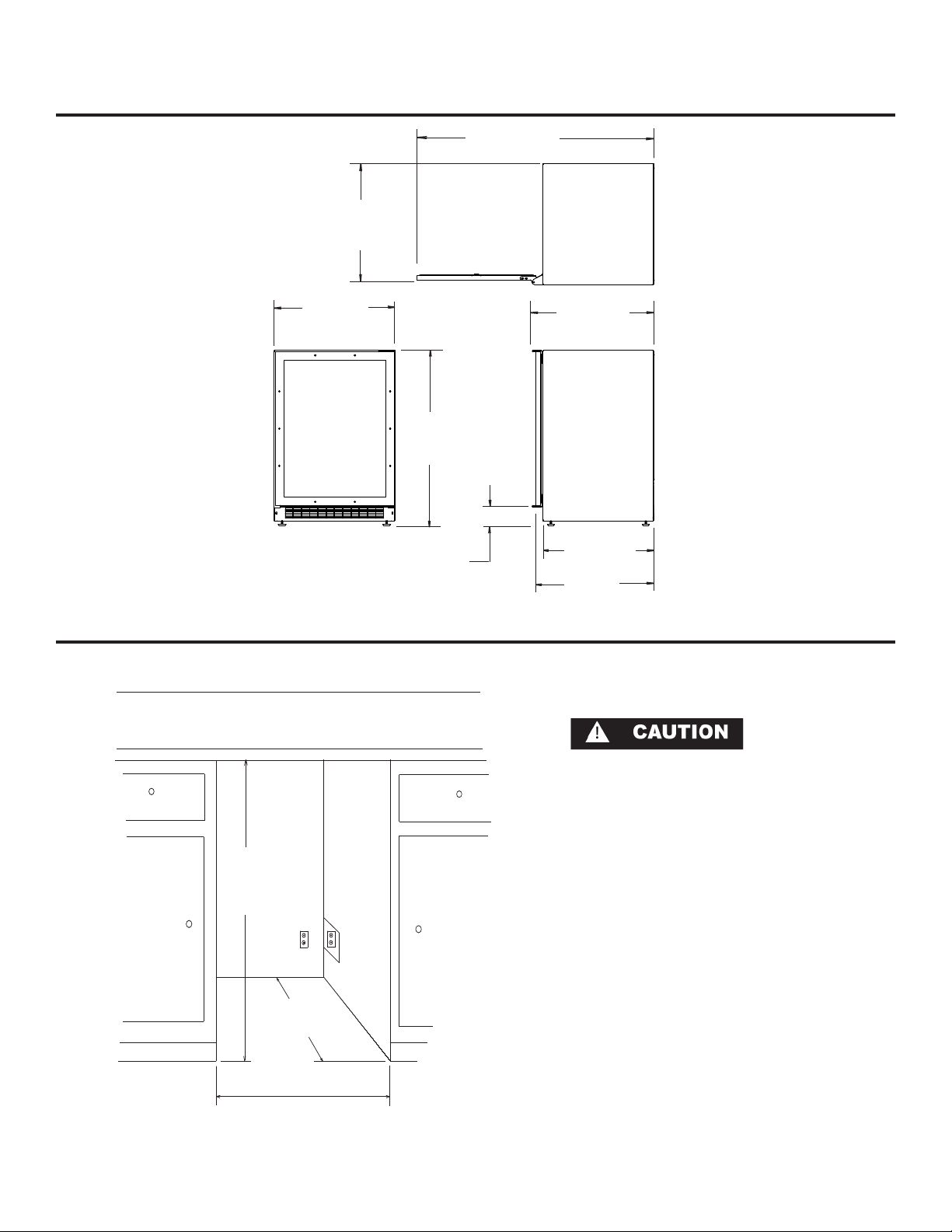
DIMENSIONS FOR 6SBARE GLASS OVERLAY DOOR
46-25/32
(118.82cm)
23-1/32”
(58.5cm)
23-7/8”
(60.66cm)
34-1/4” to 34-1/2”
(87 to 87.6cm)
3” to 3-1/4”
(7.62 to 8.26cm)
24-1/16”
(61.1cm)
22”
(55.88cm)
23-5/16”
(59.21cm)
Rough In Opening Dimensions for 6SBARE Glass Overlay Door
Electrical Requirements: 115 volts,
3.3 amps running max. 15 amp
dedicated circuit required. 3 prong
grounded receptacle required.
34-1/2”
(87.6 cm)
*24” (61 cm)
standard cabinet
depth
24” (61 cm)
Power outlet can be located in the
back wall behind unit. Add 1” to
depth for thickness of plug, or recess
outlet 1” into the wall. Power outlet
can also be installed in adjacent
cabinetry with a cutout for routing of
power cord. Follow all local building
codes when installing electrical and
unit.
Product weight = 160 lbs. (72.7 kg.)
* Depth dimension may vary depending on
each individual installation.
9
Page 11
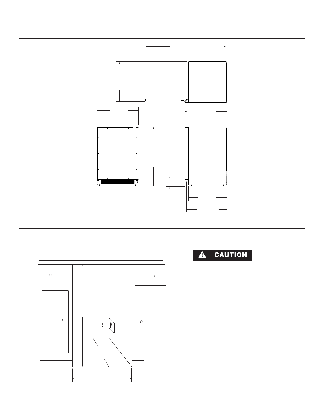
23”
(58.42cm)
DIMENSIONS FOR 6SBARE SOLID OVERLAY DOOR
46-27/32”
(119.02cm)
23-7/8”
(60.66cm)
34-1/4” to 34-1/2”
(87 to 87.6cm)
3” to 3-1/4”
(7.62 to 8.26cm)
24-1/16”
(61.1cm)
22”
(55.88cm)
23-5/16”
(59.21cm)
Rough In Opening Dimensions for 6SBARE Solid Overlay Door
34-1/2”
(87.6 cm)
*24” (61 cm)
standard cabinet
24” (61 cm)
Electrical Requirements: 115 volts,
3.3 amps running max. 15 amp
dedicated circuit required. 3 prong
grounded receptacle required.
Power outlet can be located in the
back wall behind unit. Add 1” to
depth for thickness of plug, or recess
outlet 1” into the wall. Power outlet
can also be installed in adjacent
cabinetry with a cutout for routing of
power cord. Follow all local building
codes when installing electrical and
unit.
Product weight = 160 lbs. (72.7 kg.)
depth
* Depth dimension may vary depending on
each individual installation.
10
Page 12
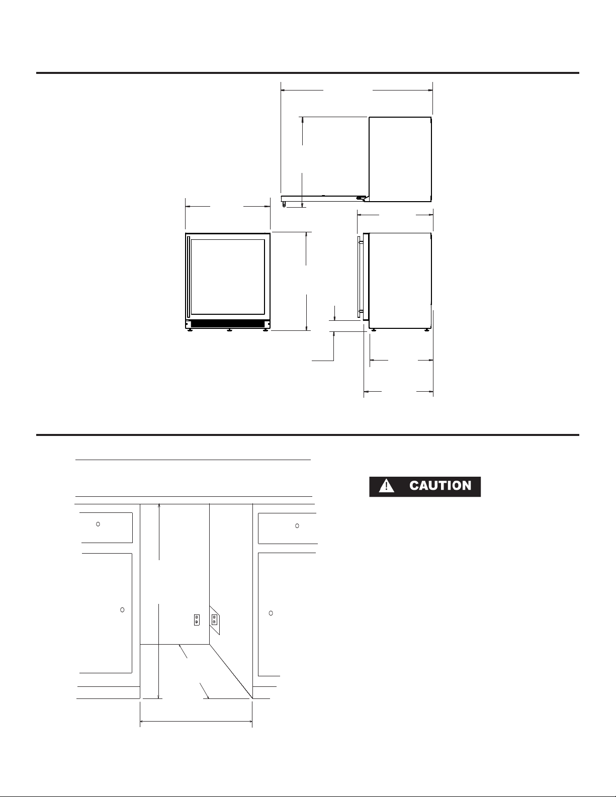
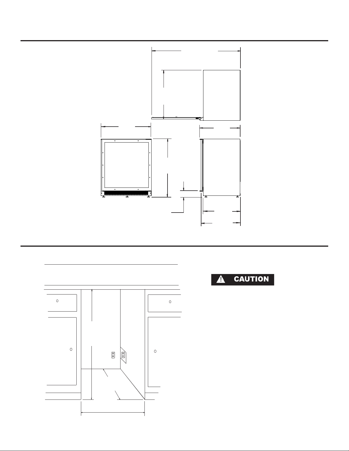
DIMENSIONS FOR 8SBARE GLASS DOOR
31-23/32”
(80.57cm)
52-31/32”
(134.54cm)
29-7/8”
(75.9cm)
34-1/4” to 34-1/2”
(87 to 87.6cm)
3” to 3-1/4”
(7.62 to 8.26cm)
Rough In Opening Dimensions for 8SBARE Glass Door
26”
(66.04cm)
22”
(55.88cm)
24-1/16”
(61.1cm)
11
34-1/2”
(87.6 cm)
*24” (61 cm)
standard cabinet
30” (76.2 cm)
Electrical Requirements: 115 volts,
3.3 amps running max. 15 amp
dedicated circuit required. 3 prong
grounded receptacle required.
Power outlet can be located in the
back wall behind unit. Add 1” to
depth for thickness of plug, or recess
outlet 1” into the wall. Power outlet
can also be installed in adjacent
cabinetry with a cutout for routing of
power cord. Follow all local building
codes when installing electrical and
unit.
Product weight = 172 lbs. (78.2 kg.)
depth
* Depth dimension may vary depending on
each individual installation.
Page 13
DIMENSIONS FOR 8SBARE GLASS OVERLAY DOOR
52-21/32”
(133.73cm)
29-1/16”
(73.81cm)
29-7/8”
(75.9cm)
34-1/4” to 34-1/2”
(87 to 87.6cm)
3” to 3-1/4”
(7.62 to 8.26cm)
24-1/16”
(61.1cm)
22”
(55.88cm)
23-5/16”
(59.21cm)
Rough In Opening Dimensions for 8SBARE Glass Overlay Door
34-1/2”
(87.6 cm)
*24” (61 cm)
standard cabinet
30” (76.2 cm)
Electrical Requirements: 115 volts,
3.3 amps running max. 15 amp
dedicated circuit required. 3 prong
grounded receptacle required.
Power outlet can be located in the
back wall behind unit. Add 1” to
depth for thickness of plug, or recess
outlet 1” into the wall. Power outlet
can also be installed in adjacent
cabinetry with a cutout for routing of
power cord. Follow all local building
codes when installing electrical and
unit.
Product weight = 172 lbs. (78.2 kg.)
depth
* Depth dimension may vary depending on
each individual installation.
12
Page 14
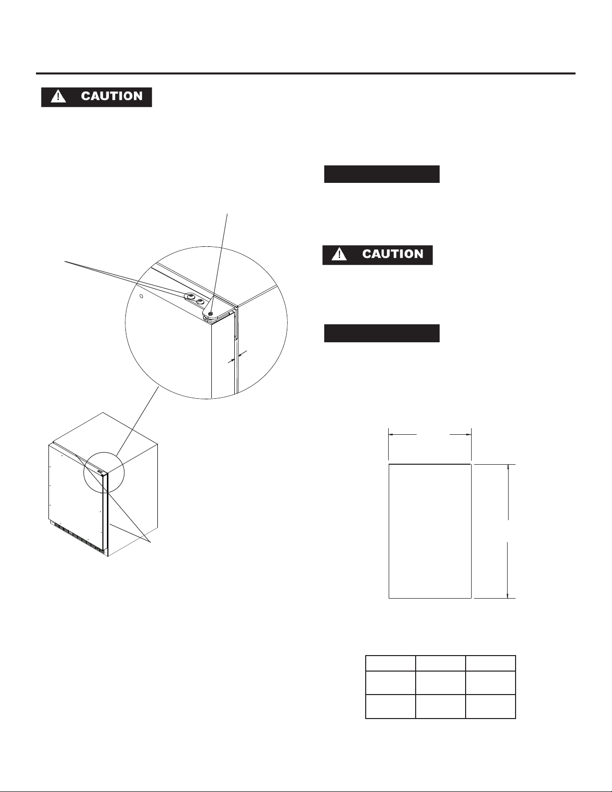
FULL OVERLAY PANEL INSTALLATION INSTRUCTIONS
NOTE
NOTE
Step 4: Cut overlay panel
Depending on the refrigerator model cut the overlay
Step 1: Verify door alignment
The door should be parallel to the sides and top of the
refrigerator. If alignment is necessary the door may be
adjusted by loosening the 2 screws which secure the
hinge adapter brackets to the door and adjusting the
door side to side. Use a 5/32” allen wrench for this procedure. (See Figure 5 below).
Top hinge pin
Hinge adapter screws loosen these to adjust door, on
remove to remove
the door.
the top and bottom of the
door
9/32”
(7mm)
panel to the dimensions shown. Use Figure 7 and Table
A for solid door models or use Figure 8 and Table B for
glass door models.
For overlay with lock option panel thickness to be
3/4” (19mm) maximum to 5/8” (16mm) minimum.
Weight of the overlay panel should not exceed 20 pounds
(9.1 kilograms).
For the door closer to work properly it is necessary to
maintain a minimum space of 9/32” (7mm) between the
door and cabinet flange as shown . This space can be
adjusted by adjusting the top and bottom hinge adapters.
Door must be
parallel to top
Figure 6
and sides of
refrigerator
Step 2: Remove door
Remove the top hinge pin from the hinge with an 1/8”
allen wrench. Remove the door by angling the top of the
door outward and lifting the door off the bottom hinge.
(See detail in Figure 6).
Step 3: Remove gasket
Lay the door on its front being careful not to scratch it.
Remove the door gasket by peeling up and out of the
channel.
W
Front of
overlay
panel
Figure 7
Solid Door Models
Model W H
3SBARE
6SBARE
14-5/8”
(37.13cm)
23-5/8”
(59.99cm)
30-5/16”
(76.99cm)
30-5/16”
(76.99cm)
H
13
Table A
Solid Door Models
Page 15
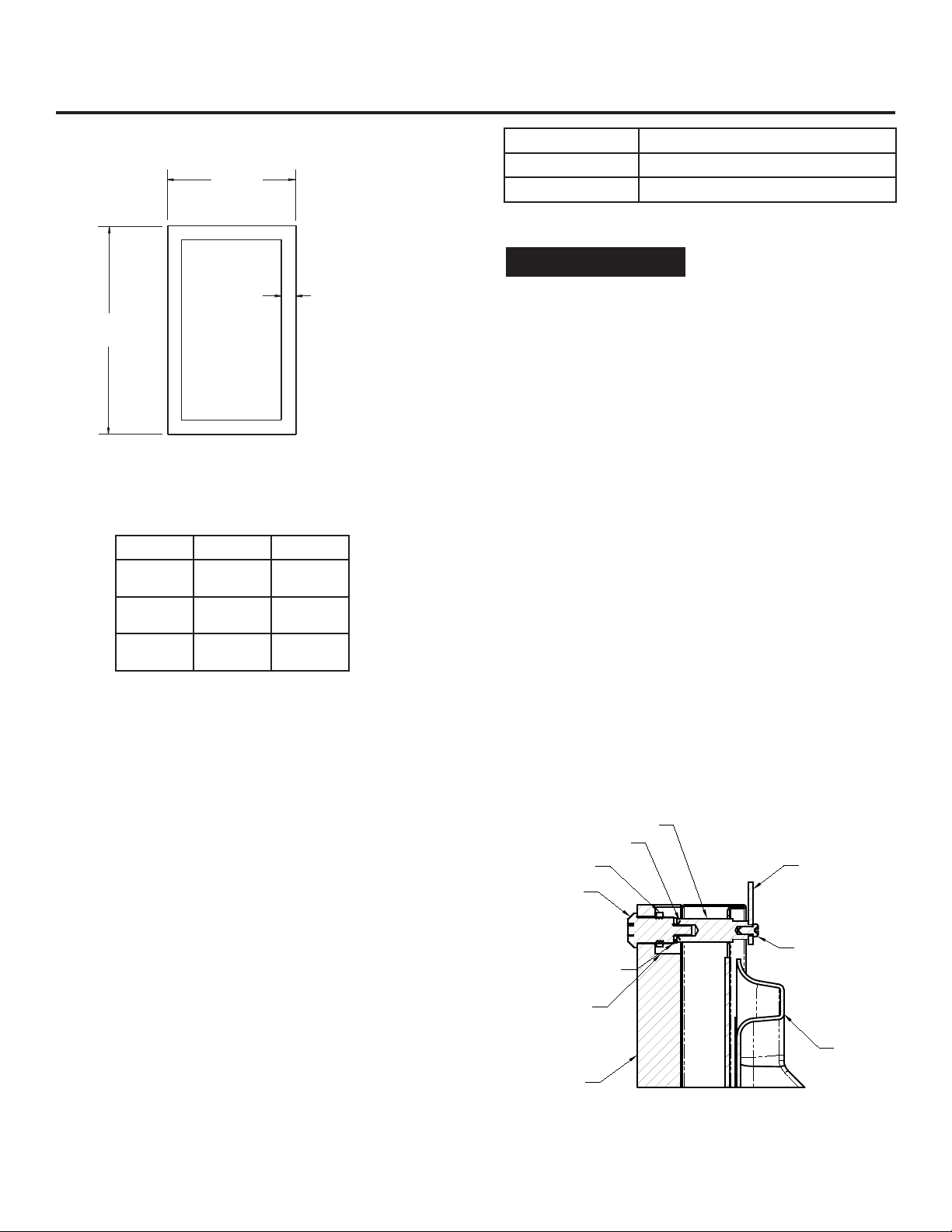
W
NOTE
NOTE
SECTION A-A
SCALE 1 : 1
LOCK
NUT
BRASS EXTENSION
CAM
PHILLIPS SCREW
13/16 COUNTER
BORE 7/16 DEEP
15/32 HOLE
3/4 INCH
WOOD PANEL
SPRING WASHER
INNER
DOOR
FULL OVERLAY PANEL INSTALLATION INSTRUCTIONS
Material Type #8 Wood Screw
Hardwood 3/32” (2.4mm) Diameter. Pilot Hole
Softwood 5/64 (2.0mm) Diameter. Pilot Hole
Table C
H
Front of
overlay
panel
Figure 8
Glass Door Models
Model W H
3SBARE
6SBARE
8SBARE
14-5/16”
(36.35cm)
23-7/16”
(59.54cm)
29-7/16”
(74.78cm)
Table B
Glass Door Models
1-23/32”
(38.77cm)
30-5/16”
(76.99cm)
30-5/16”
(76.99cm)
30-5/16”
(76.99cm)
Typical 4
Sides
If your refrigerator has a door lock proceed to Step 7.
If your refrigerator does not have a door lock proceed
to Step 9.
Step 7: Mark and drill lock hole.
Locate and mark with a pencil the location of the lock
hole on the overlay panel, this is the hole in the top corner of the handle side of the door. Remove the clamp and
remove the overlay panel from the door. On the backside
of the panel where you marked the lock location drill a
13/16” (20.5mm) diameter counterbore 7/16” (11.0mm)
deep into the overlay panel. Drill a 15/32” (12.0mm)
diameter hole through the overlay panel centered on the
counterbore being careful not to splinter the wood on the
face side of the panel. (See Figure 9).
Step 8: Assemble the lock parts
Two (2) lock extensions are supplied with the lock. Use
the longer extension for a 3/4” thick overlay panel and
the shorter one for a 5/8” thick panel. Assemble the lock
extension, cam stop washer, spring washer, and set screw
to the lock as shown in Figure 9 and 10.
Install this assembly into the overlay panel and secure
with the retaining nut using a 15mm socket. Make sure
the key slot in the lock is vertical.
Step 5: Clamp panel to door
Set the overlay panel on the door front, align the edges,
and clamp together. Clamp the panel firmly but be careful not to crush the foam in the door or scratch the door.
Step 6: Drill holes in overlay panel
Remove the hinge adapter bushings from the top and
bottom door hinge adapters. (See Figure 11).Using the
holes in the hinge adapters drill 5/16” (8mm) diameter
clearance holes into the overlay panels 3/4” (20mm)
deep. These will be clearance holes for the top and bottom hinge pins.
Also at this time drill the screw pilot holes for attaching the overlay panel to the door. Select the size of the
hole from Table C. Be careful not to drill the pilot holes
through the overlay panel but only 1/2” (12.7)mm deep.
Figure 9
14
Page 16
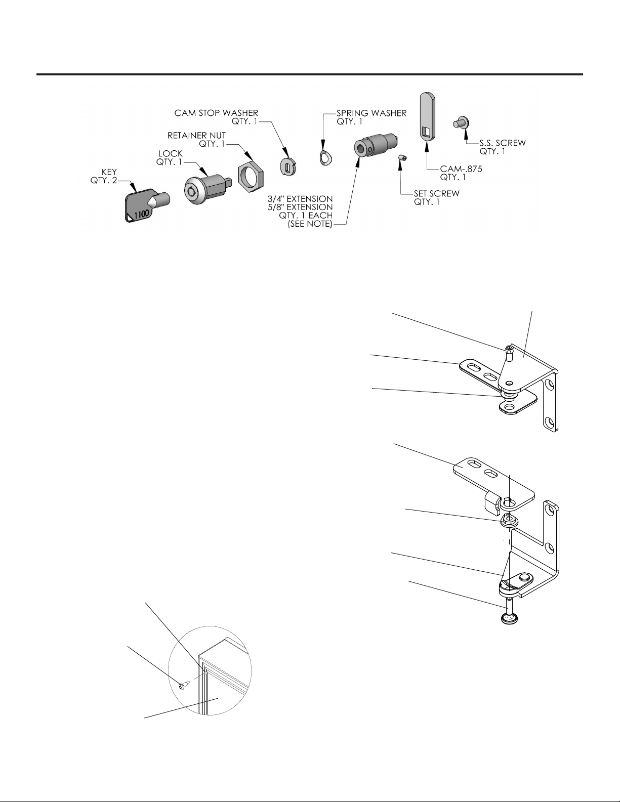
FULL OVERLAY PANEL INSTALLATION INSTRUCTIONS
Figure 10
Step 9: Secure overlay panel to the door.
With the #8 wood screws provided fasten the overlay
panel to the door. (See Figure 11).
Step 10: Install lock cam (Models with locks only).
Attach the lock cam to the back of the lock assembly with
the phillips head machine screw provided. Orient the lock
cam vertically when installing on the lock.
Step 11: Install door gasket
Press the door gasket into the door channel. Make
certain the gasket corners are fully inserted. If applicable
insert the key into the lock and make certain the lock
operates properly.
Top hinge pin
Top door hinge
adapter
Top hinge adapter
bushing
Bottom door
hinge adapter
Top hinge
Step 12: Install the door
Install the top and bottom hinge adapter bushings back
into the hinge adapters that were removed in step 6.
Install the door by reversing the procedure from step 2.
Install the top hinge pin so the screw head is flush with
the top surface of the hinge. If applicable insert key into
lock and verify the lock cam works properly with the
catch bracket on the front of the refrigerator cabinet.
Clearance hole through
door gasket channel
#8 Wood Screw
Back of door
Figure 11
15
Bottom hinge
adapter bushing
Bottom hinge
with cam
Bottom hinge pin
Figure 12
Right hand
hinges shown
Page 17
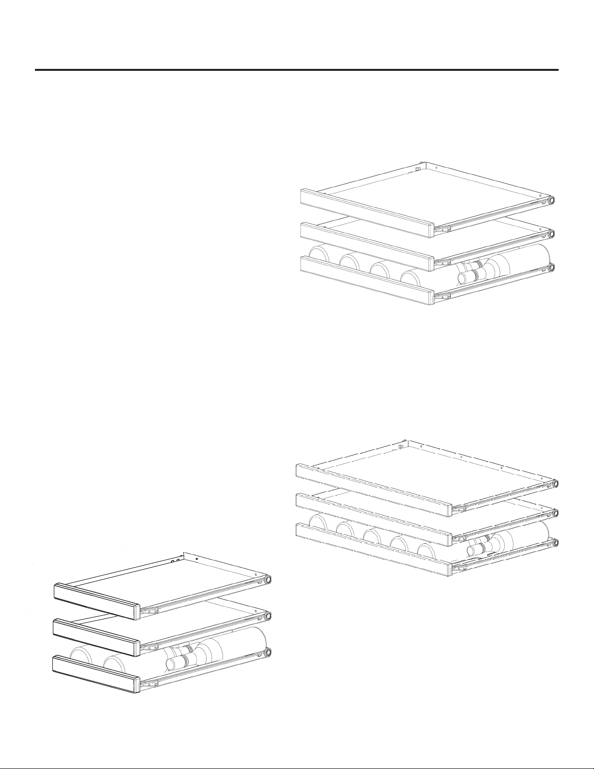
Insert Wine Bottles
The wine rack roll-out shelf holds four (4) bottles to ten (10)
bottles of wine depending on model. See Figure 13 to 15
for typical wine bottle orientation.
Loading Tips and Suggestions
Your beverage center comes with sliding glass shelves and
(1) wine shelf. The wine shelf should be located in the lowest position in the cabinet followed by a glass shelf directly
above. This glass shelf will help keep your wine shelf between 5° & 7°F warmer than the rest of the cabinet, which
is ideal for wine storage.
Keep wines that you plan to use for everyday drinking and
entertaining on the front half of the shelf where labels are
completely visible. Place wines for aging or longer term
storing in the rear.
Wine Shelf
Since bottles are not stacked on top of each other, you can
easily view and access your inventory without disturbing
other bottles.
FEATURES FOR BEVERAGE REFRIGERATORS
Figure 14
6SBARE
Roll-out Shelves
The roll-out shelves may be pulled out approximately 14
inches to facilitate adding or removing beverages. Do
NOT lean on or press down heavily on the shelves. Doing
so may damage the shelves and/or the contents stored on
them. Pull the shelves out gently and carefully to minimize
any possible item shifting. AVOID pulling out more than
one (1) shelf at any time to maintain stability.
Figure 15
8SBARE
Figure 13
3SBARE
16
Page 18
CARE AND CLEANING
Condenser
The condenser tubing inside the cabinet does not require
frequent cleaning; however, satisfactory cooling depends
on adequate ventilation over the coils. Be sure that nothing obstructs the required air flow openings in front of the
cabinet. At least once or twice a year, brush or vacuum lint
and dirt from the front grille area (see page 3).
Cabinet
The stainless steel cabinet can be washed with either a
stainless steel cleaner or a mild soap and water and thoroughly rinsed with clear water. NEVER use abrasive scouring cleaners. Painted surfaces can be cleaned with mild
soap and water.
Interior
Wash interior compartment with mild soap and water. Do
NOT use an abrasive cleaner, solvent, polish cleaner or
undiluted detergent.
Shelves
The racks may be cleaned with mild soap and water and a
soft cloth. Do NOT use any abrasive cleaners. See below
for instructions for removing the shelves.
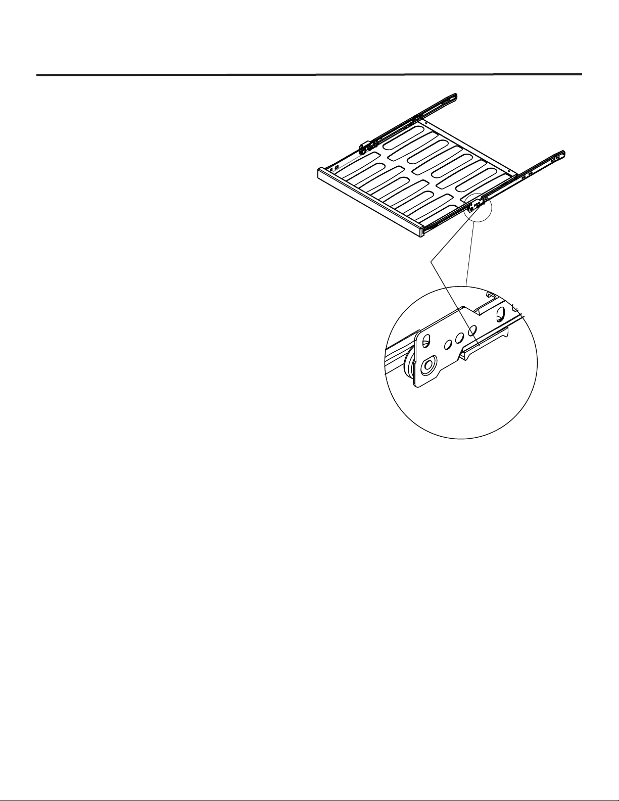
Figure 17
Plastic Block on
bottom front of slide
Door Gasket
The vinyl gasket may be cleaned with mild soap and water,
a baking soda solution or a mild scouring powder.
Removing the Wine Shelves.
Unload the shelf to be removed. Pull the shelf all the way
out until it stops. At the front of the drawer slide just under
the shelf there is a plastic block (see Figure 17). Push this
block to the rear to release the slide. Repeat on other side
of the shelf. Lift the front of the shelf and pull away from
the slides to remove the shelf.
Reverse this procedure to install the shelf. Be sure to move
the plastic block to the forward position after installing the
shelf.
17
Page 19
CARE AND CLEANING
Light Tube Replacement
DISCONNECT THE POWER CORD BEFORE ATTEMPTING
LIGHT TUBE REPLACEMENT. Failure to do so may result in
an electrical shock that could severely injure you.
The 3SBARE uses one, 6 watt light tube. The 6SBARE and
8SBARE use two, 6 watt light tubes to illuminate the interior
of the refrigerator. The light tube is a very reliable electrical
component, but should it not function properly, please call
the dealer you purchased your refrigerator from for a replacement light tube. Use only an original equipment light
tube from your dealer or Northland-Marvel.
It may be necessary to remove 1 or 2 shelves directly below
the light tube to gain access for removal. See page 21 for
instructions on removing the shelves.
Do NOT under any circumstance use a light tube that exceeds 10 watts!
The light tubes are not covered by your warranty. Replacement tubes can be obtained from your dealer or from
Northland-Marvel.
In the Event of a Power Failure
If a power failure occurs, try to correct it as soon as possible. Minimize the number of door openings while the
power is off so as not to adversely affect the unit’s temperature.
To replace a light tube, use a hex-head driver, remove the
two hex-head screws that hold a cover plate over the back
section of the light tube. Set the screws and cover plate
aside for reassembly later.
Using a small flat-blade screwdriver, gently lever the front
section of the light tube down to allow it to be pulled clear of
the light housing.
Disconnect the two insulated electrical connectors from the
cabinet’s electrical cable and discard the old light tube. Reconnect the electrical connector of the new light tube to the
cabinet’s electrical cable connectors. Make sure it is secure
and fully installed.
Carefully realign the light tube’s electrical terminal back into
the rear of the light enclosure channel making sure not to
crimp them. Gently insert the light tube along the length of
the light enclosure channel. Press the light tube gently into
the light enclosure channel. Only a small part of the light
tube should project below the ceiling of the refrigerator. DO
NOT USE A HAMMER TO FIT THE LIGHT TUBE.
Place the light tube terminal cover plate back in the original
position on the light enclosure’s flange. Reuse the original
two screws to secure it in place. Plug the refrigerator into
the electrical socket. Check to see if the light tube operates
properly. Your light tube’s replacement is complete.
18
Page 20
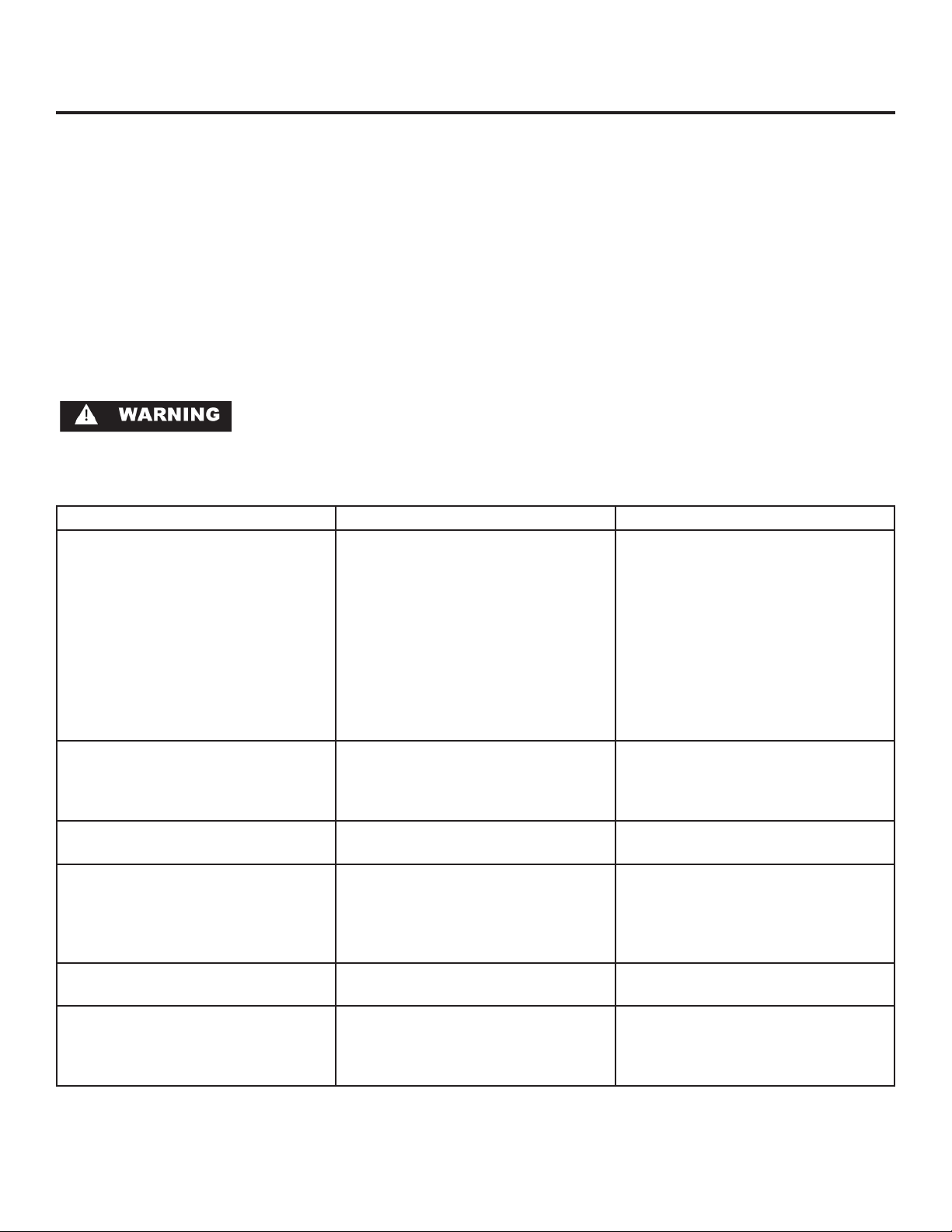
TROUBLESHOOTING YOUR BEVERAGE REFRIGERATOR
Before You Call for Service
If the unit appears to be malfunctioning, read through this
manual first. If the problem persists, check the troubleshooting guide below. Locate the problem in the guide and refer
to the cause and its remedy before calling for service. The
problem may be something very simple that can be solved
without a service call. Some remedies listed in the Troubleshooting Guide are very complex. Consulting or contracting
a qualified service technician may be necessary.
Electrocution Hazard - Never attempt to repair or perform maintenance on the unit until the main electrical power has
been disconnected.
Problem Possible Cause Remedy
Unit not cold enough
Adjust temperatures (See “Changing
Current Settings” on page 4 or 5)
Control set too warm•
Airflow to front grille blocked.•
Excessive usage or prolonged •
drawer openings.
Door gasket not sealing properly.•
Adjust temperature colder. Al-•
low 24 hours for temperature to
stabilize.
Airflow must not be obstructed to •
front grille. See “clearances” on
page 3.
Allow temperature to stabilize for •
at least 24 hours.
Adjust or replace door gasket.•
Unit too cold
Adjust temperatures (See “Changing
Current Settings” on page 4 or 5)
No interior light. Failed LED interior light assembly• Contact a qualified Marvel service •
Light will not go out when drawer is
closed
Noise or Vibration Unit not level• Level unit, see “Leveling Legs” on •
Unit will not run. Unit turned off•
19
Control set too cold• Adjust temperature warmer. (See •
Door not activating light switch.• Verify cabinet is level, refer to page •
Power cord not plugged in.•
No power at outlet.•
page 12, “set the desired temperature”). Allow 24 hours for temperature to stabilize.
technician.
3 for leveling instructions.
Verify the door is aligned properly, •
refer to page 13 for instructions.
page 3.
Turn unit on. See “Start your Appli-•
ance” on page 4 or 5.
Plug in power cord.•
Check house circuit.•
Page 21
If Service is Required:
If the product is within the first year warranty period •
please call Marvel Customer Service at 800.223.3900
for directions on how to obtain warranty coverage in
your area.
If the product is outside the first year warranty period, •
Marvel Customer Service can provide recommendations
of service centers in your area. A listing of authorized
service centers is also available at www.marvelrefrigeration.com under the service and support section.
In all correspondence regarding service, be sure to give •
the model number, serial number, and proof of purchase.
Try to have information or description of nature of the •
problem, how long the unit has been running, the room
temperature, and any additional information that may
be helpful in quickly solving the problem.
Fill in pertinent information below regarding your prod-•
uct for future reference.
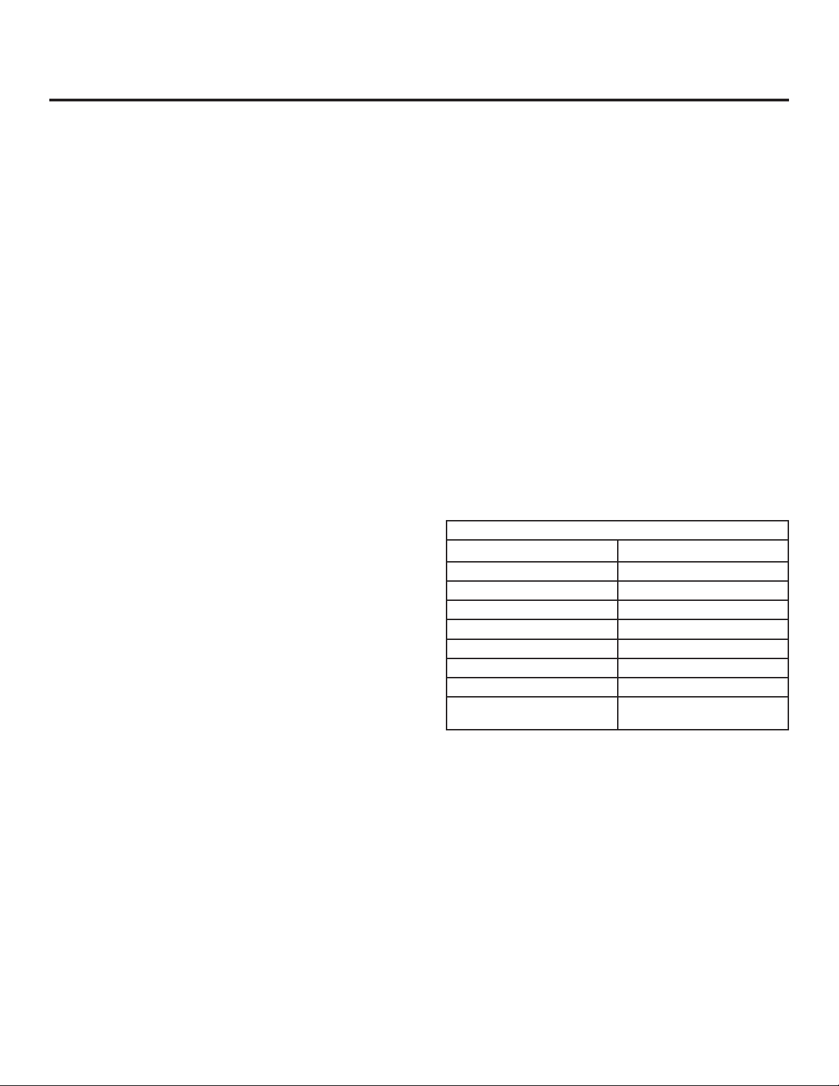
HOW TO OBTAIN SERVICE
For You Records
Date of Purchase
Dealer’s name
Dealer’s Address
Dealer’s City
Dealer’s State
Dealer’s Zip Code
Appliance Serial Number
Appliance Model Number
Date Warranty Card Sent (Must
be within 10 days of purchase).
20
Page 22

HOUSEHOLD PRODUCT WARRANTY
Entire Product
Limited One Year Parts and Labor Warranty
Marvel warrants that it will supply all necessary parts and
labor to repair or replace in the end user’s home or office,
any component which proves to be defective in material
or workmanship, subject to the condition and exclusions
stated below, for a period of one year from the date of
purchase by the end user.
Additional Second Through Fifth Year
Limited Parts Only Warranty
During the four years following expiration of the one year
limited warranty, Marvel will supply replacement parts for
the hermetically sealed refrigeration system which consists
of the compressor, condenser, drier, accumulator, bypass
valve, connecting tubing and the evaporator that are
proven to be defective due to workmanship or materials
subject to the conditions and exclusions below.
The above warranties do not cover:
Shipping costs of replacement parts or returned defec-•
tive parts.
Customer education or instructions on how to use the •
appliance.
Any content loss due to product failure.•
Removal or installation of product.•
Nor do the above warranties cover failure of this product or
its components due to:
Transportation or subsequent damages.•
Commercial use or use other than normal household •
or small office.
Improper installation, misuse, abuse, accident or •
alteration, use of wiring not conforming to electrical
codes, low or high voltages, failure to provide necessary maintenance, or other unreasonable use.
Parts or Service
Not Supplied or Designated by Marvel
The above warranties also do not apply if:
The original bill of sale, deliver date, or serial number •
cannot be verified.
Defective parts are not returned for inspection if so •
requested by Marvel.
The refrigeration equipment is not in the possession of •
the original end use purchaser.
The warranties set forth herein are the only warranties
extended by Northland-Marvel. Any implied warranties, including the implied warranty of merchantability, are limited
to the duration of these express warranties. In no event
shall Northland-Marvel be liable for any consequential or
incidental damages or expenses resulting from breach of
these or any other warranties, whether express or implied.
Some states do not allow the exclusion or limitation of consequential damages or a limitation on how long an implied
warranty lasts, so the above exclusion or limitation may not
apply to you. This warranty gives you specific legal rights
and you may have other rights that may vary from state to
state.
No person, firm, or corporation is authorized to make any
other warranty or assume any other obligation for Northland-Marvel. These warranties apply only to products used
in any of the fifty states of the United States and the District
of Columbia.
To obtain performance of this warranty, report any defects
to:
Northland-Marvel
P.O. Box 400
1260 E. Van Deinse St.
Greenville MI 48838
21
Phone: 800.223.3900
Page 23

NOTES
22
Page 24

Northland-Marvel
P.O. Box 400
1260 E. Van Deinse St.
Greenville MI 48838
800.223.3900
www.marvelrefrigeration.com
41011767-EN Rev J
12/05/09
All specifications and product designs subject to change without notice. Such revisions do not entitle
the buyer to corresponding changes, improvements, additions, replacements or compensation for
previously purchased products.
 Loading...