

Page 1
RUSH® MH 11 Beam
User Manual
Page 2

Information subject to change without notice. HARMAN Professional Denmark ApS
disclaims liability for any injury, damage, direct or indirect loss, consequential or economic
loss or any other loss occasioned by the use of, inability to use or reliance on the
information contained in this document.
©2017 HARMAN Professional Denmark ApS. All rights reserved. Martin® and RUSH®
are registered trademarks of HARMAN Professional Denmark ApS registered in the
United States and/or other countries. Features, specifications, and appearance are
subject to change without notice.
Martin Professional • Olof Palmes Allé 18 • 8200 Aarhus N • Denmark • www.martin.com
RUSH® MH 11 Beam User Manual: Revision B
Page 3

Table of contents
Safety information ...................................................................................... 5
Introduction .............................................................................................. 11
Before using the product for the first time .......................................... 11
Maximizing lamp life ........................................................................... 11
Physical installation ................................................................................. 12
Fastening the fixture to a flat surface ................................................. 12
Mounting the fixture on a truss ........................................................... 12
AC power ................................................................................................. 14
Linking fixtures to power in a chain .................................................... 14
Fixture overview ....................................................................................... 16
Control data link ....................................................................................... 17
Tips for reliable data transmission ...................................................... 17
Connecting the data link ..................................................................... 18
Fixture setup ............................................................................................ 19
Using the control menus ..................................................................... 19
Setting DMX address .......................................................................... 19
Lamp control settings ......................................................................... 20
Fixture settings ................................................................................... 21
Fixture information .............................................................................. 23
Position calibration ............................................................................. 24
Setting options by RDM ........................................................................... 24
Scanning for RDM devices on the data link ....................................... 24
Getting status and setting options by RDM ........................................ 25
RDM functions .................................................................................... 25
Effects ...................................................................................................... 27
Dimming .............................................................................................. 27
Strobe effects ..................................................................................... 27
Pan and tilt .......................................................................................... 27
Colors ................................................................................................. 27
Gobos ................................................................................................. 28
Prism ................................................................................................... 28
Focus .................................................................................................. 28
Frost .................................................................................................... 28
Maintenance ............................................................................................ 29
Cleaning.............................................................................................. 29
Replacing gobos ................................................................................. 30
Lamp replacement .............................................................................. 32
Lamp temperature control .................................................................. 34
Replacing the primary fuse ................................................................. 34
Page 4

Updating firmware............................................................................... 34
Service and repairs ............................................................................. 34
DMX protocol ........................................................................................... 35
Control menus ......................................................................................... 39
Troubleshooting ....................................................................................... 41
Specifications ........................................................................................... 42
Page 5
Safety information
WARNING!
Read the safety precautions in this manual before
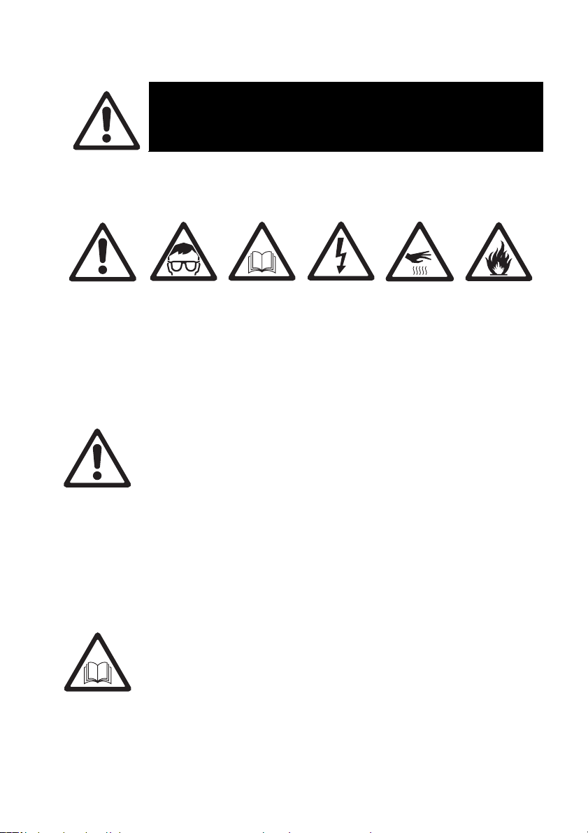
The following symbols are used to identify important safety information on
the product and in this manual:
installing, operating or servicing this product.
Warning!
Safety
hazard. Risk
of severe
injury or
death.
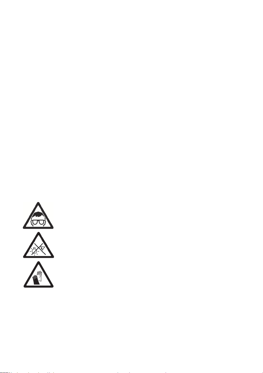
Warning!
Powerful
light
emission.
Risk of eye
injury.
Warning!
See user
manual for
important
safety
information.
Warning!
Hazardous
voltage.
Risk of
lethal or
severe
electric
shock.
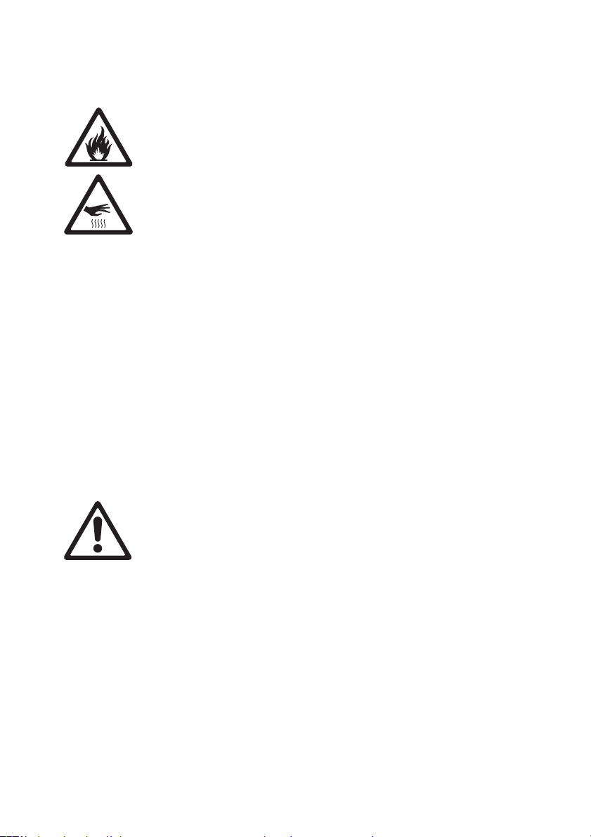
Warning!
Hot
surfaces.
Warning!
Fire hazard.
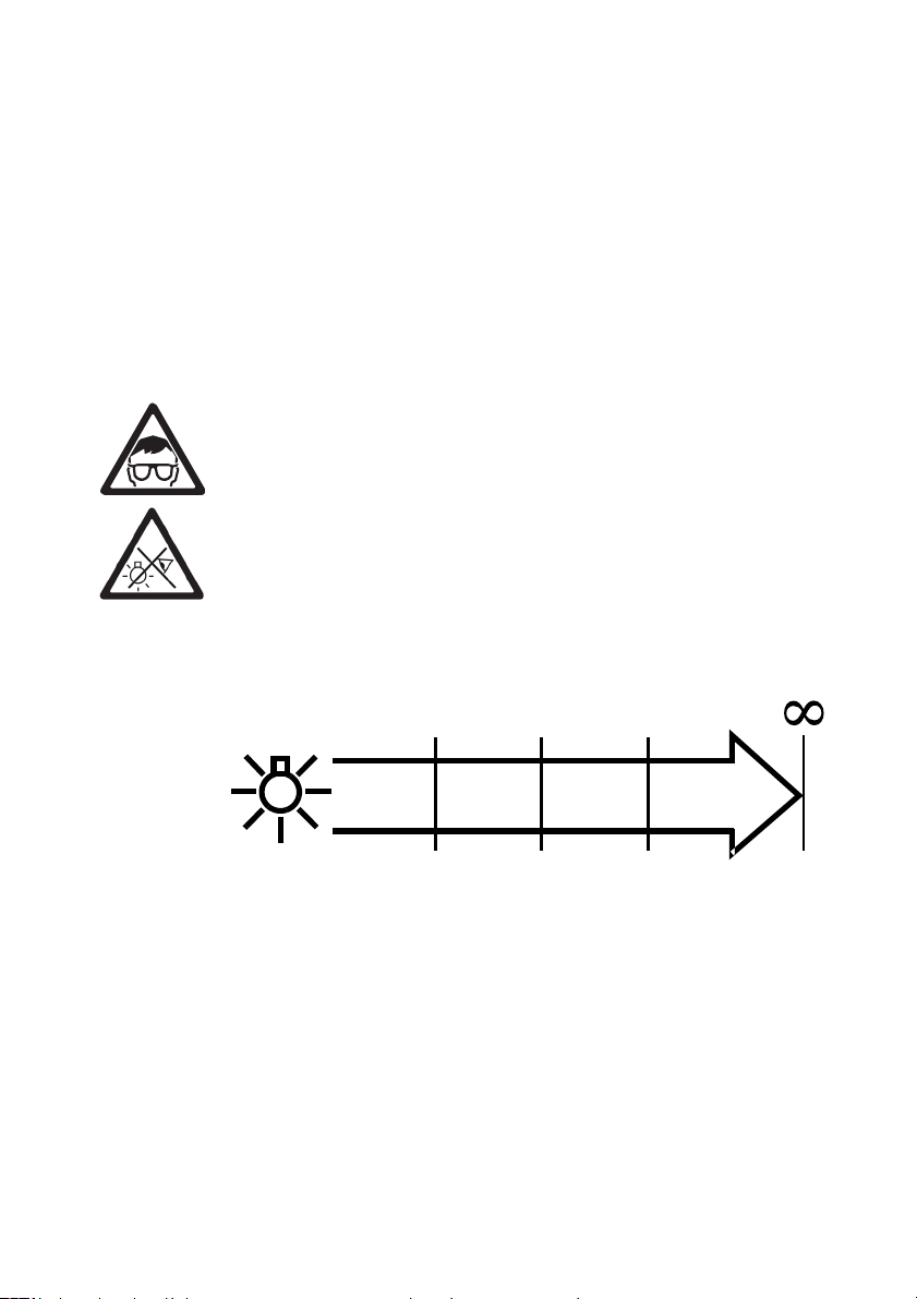
Warning! Risk Group 3 (high risk) product according to EN
62471. Possibly hazardous radiation emitted from this
product. May be harmful to the eyes. Do not stare at
operating lamp and do not view the light output with optical
instruments or any device that may concentrate the beam.
This lighting fixture is for professional use only and must be
installed by a qualified technician. It is not for household use.
It presents risks of severe injury or death due to fire hazards,
electric shock and falls. It produces a powerful, concentrated
beam of light that can create a fire hazard or a risk of eye
injury if the safety precautions below are not followed.
Install, operate and service Martin® products only as directed
in their user manuals, or you may create a safety hazard or
cause damage that is not covered by product warranties.
Follow the safety precautions listed below and observe all
warnings in this manual and printed on the product. Keep this
user manual for future use.
RUSH® MH 11 Beam User Manual 5
Page 6

For the latest user documentation and other information for
this and all Martin® products, please visit the Martin website
at http://www.martin.com
If you have any questions about how to install, operate or
service the fixture safely, please contact your Martin®
distributor (see www.martin.com/where-to for details) or call
the Martin® 24-hour service hotline on +45 8740 0000, or in
the USA on 1-888-tech-180.
Respect all locally applicable laws, codes and regulations
when installing, operating or servicing the fixture.
Protection from electric shock
Do not expose the fixture to rain or moisture.
Disconnect the fixture from AC power before carrying out any
installation or maintenance work and when the fixture is not in
use.
Ensure that the fixture is electrically connected to ground
(earth).
Use only a source of AC power that complies with local
building and electrical codes and has both overload and
ground-fault (earth-fault) protection.
Socket outlets or external power switches used to supply the
fixture with power must be located near the fixture and easily
accessible so that the fixture can easily be disconnected from
power.
Replace defective fuses with ones of the specified type and
rating only.
Isolate the fixture from power immediately if the power plug or
any seal, cover, cable, or other component is damaged,
defective, deformed, wet or showing signs of overheating. Do
not reapply power until repairs have been completed
Before using the fixture, check that all power distribution
equipment and cables are in perfect condition and rated for
the electrical requirements of all connected devices.
The mains power input cable supplied with the fixture can
safely supply only one fixture with mains power. Do not
connect any device to the fixture’s MAINS OUT socket when
using this input cable. If you want to connect other fixtures to
6 RUSH® MH 11 Beam User Manual
Page 7
the MAINS OUT socket, see ‘Linking fixtures to power in a
chain’ on page 14.
Protection from burns and fire
Do not operate the fixture if the ambient temperature (T
exceeds 40° C (104° F).
a
The surface of the product casing can reach up to 100° C
(212° F) during operation. Avoid contact by persons and
materials. Allow the fixture to cool for at least 10 minutes
before handling.
Keep flammable materials well away from the fixture. Keep all
combustible materials (e.g. fabric, wood, paper) at least 200
mm (8 in.) away from the fixture head.
Ensure that there is free and unobstructed airflow around the
fixture. Provide a minimum clearance of 0.5 m (20 in.) around
fans and air vents.
Do not illuminate surfaces within 10 m (33 ft.) of the fixture.
Do not attempt to bypass thermostatic switches or fuses.
Do not stick filters, masks or other materials onto any optical
component.
The fixture’s lenses can focus the sun’s rays inside the
fixture, creating a risk of fire and damage. Do not expose the
front of the fixture to sunlight or any other bright light source.
)
Protection from injury
Fasten the fixture securely to a fixed surface or structure
when in use. The fixture is not portable when installed.
Ensure that any supporting structure and/or hardware used
can hold at least 10 times the weight of all the devices they
support.
If suspending from a rigging structure, fasten two (2) suitable
rigging clamps to the fixture. Do not use safety cables as the
primary means of support.
If the fixture is installed in a location where it may cause
injury or damage if it falls, install as directed in this manual a
secondary attachment such as a safety cable that will hold
the fixture if a primary attachment fails. The secondary
attachment must be approved by an official body such as
TÜV as a safety attachment for the weight that it secures,
RUSH® MH 11 Beam User Manual 7
Page 8
must comply with EN 60598-2-17 Section 17.6.6 and must be
capable of bearing a static suspended load that is ten times
the weight of the fixture and all installed accessories.
Allow enough clearance around the head to ensure that it
cannot collide with an object or another fixture when it moves.
Check that all external covers and rigging hardware are
securely fastened.
Block access below the work area and work from a stable
platform whenever installing, servicing or moving the fixture.
Do not operate the fixture with missing or damaged covers,
shields or any optical component.
Do not lift or carry the fixture by its head. Support the fixture
by its base only.
In the event of an operating problem, stop using the fixture
immediately and disconnect it from power. Do not attempt to
use a fixture that is obviously damaged.
Do not modify the fixture in any way not described in this
manual or install other than genuine Martin® parts.
Refer any service operation not described in this manual to a
qualified technician.
Lamp safety
Install only a lamp that is approved by Martin® for use in the
product.
Prolonged exposure to an unshielded discharge lamp can
cause eye and skin burns. Do not look at an exposed lamp
while it is lit. Do not operate the fixture with missing or
damaged covers, shields, lenses, ultraviolet screens or any
optical component.
A hot discharge lamp is under pressure and can explode
without warning. Allow the fixture to cool for at least 2 hours
and protect yourself with safety glasses and gloves before
handling a lamp.
Replace the lamp immediately if it becomes visually
deformed, damaged or in any way defective.
Monitor hours of lamp use. Replace the lamp before or when
it reaches its average lifetime as specified in this manual or
by the lamp manufacturer or if you notice a fall in light output.
8 RUSH® MH 11 Beam User Manual
Page 9
If you exceed the average lamp lifetime, the lamp may
explode and damage the fixture.
If the quartz envelope of a discharge lamp is broken, the
lamp releases a small quantity of mercury and other toxic
gases. If a discharge lamp explodes in a confined area,
evacuate the area and ventilate it thoroughly for 30 minutes.
Wear nitrile gloves when handling a broken discharge lamp.
Do not use a vacuum cleaner to remove pieces of a broken
lamp. Treat broken or used discharge lamps as hazardous
waste: put them in a plastic bag and send to a specialist for
disposal.
Protection from eye injury
Warning! Risk Group 3 (high risk) product according to
EN 62471.
Do not look directly into the product’s light output.
Do not look at operating lamp. Eye injury may result.
Do not expose persons to the product’s light output from a
distance of less than 30 m (98 ft.).
The fixture falls into the following Risk Groups according to
EN62471 for blue light at the distances indicated below:
30 m
(98 ft.)
305 m
(1000 ft.)
3050 m
(10000 ft.)
RISK GROUP
3
RISK GROUP
2
RISK GROUP
1
RISK GROUP
EXEMPT
Avoid eye or skin exposure to unshielded product. UV
emitted from this product. Possibly hazardous optical
radiation emitted from this product.
Do not look at the light output with magnifiers, telescopes,
binoculars or similar optical instruments that may concentrate
the light output.
Ensure that persons are not looking directly into the front of
the fixture when the product lights up suddenly. This can
happen when power is applied, when the product receives a
DMX signal, or when certain control menu items are selected.
RUSH® MH 11 Beam User Manual 9
Page 10

To minimize the risk of eye irritation or injury, disconnect the
fixture from power at all times when the fixture is not in use
and provide well-lit conditions to reduce the pupil diameter of
anyone working on or near the fixture.
10 RUSH® MH 11 Beam User Manual
Page 11

Introduction
The RUSH® MH 11 Beam is a powerful profile fixture with a Philips MSD
Platinum 11R 250W short-arc discharge lamp that produces a high intensity
beam. The fixture provides 540° of pan movement, 260° of tilt movement,
motorized focus lens, smooth full-range dimming, strobing shutter and pulse
effects, 8 user-replaceable rotating gobos, 13 color filters, a rotating prism,
and a frost filter. The short-arc source and rugged, lightweight construction
make it ideal for live shows, TV events, stage, concerts, and nightclubs.
The RUSH® MH 11 Beam can be controlled using any DMX-compliant
controller and may be remotely configured by RDM. It is supplied with this
user manual, a 1.5 m (4.9 ft.) power cable ready for a local power plug (not
included), and two mounting brackets for attachment of suitable, usersupplied rigging clamps.
Before using the product for the first time
1. Read ‘Safety information’ on page 5 before installing, operating or
servicing the fixture.
2. Unpack and ensure that there is no transportation damage before using
the fixture. Do not attempt to operate a damaged fixture.
3. If the fixture is not going to be hard-wired to a mains supply, install a
local power plug (not supplied) on the end of the supplied power cable.
4. Ensure that the voltage and frequency of the power supply match the
power requirements of the fixture.
5. Check the support pages on the Martin Professional website at
www.martin.com for the most recent user documentation and technical
information about the fixture. Martin® user manual revisions are
identified by the revision letter at the bottom of the inside cover.
Note that whenever AC power is applied to the fixture, it will reset all effects
and functions to their home positions. Be prepared for the fixture head to
move. A reset usually takes around 20 seconds.
Maximizing lamp life
To obtain maximum output over the lifetime of the fixture’s lamp:
• Each time you power the lamp on, allow it to warm up for at least 5
minutes before you power it off.
• Before shutting down power completely, power the lamp off but leave
power applied to the fixture for a few minutes so that cooling fans can
prevent any momentary lamp temperature increase caused by heat
from surrounding components.
RUSH® MH 11 Beam User Manual 11
Page 12
Physical installation
Warning! Read ‘Safety information’ on page 5 before
installing the fixture.
The fixture is designed for indoor use only and must be used
in a dry location with adequate ventilation. Ensure that none
of the fixture’s ventilation slots are blocked.
Fasten the fixture to a secure structure or surface. Do not
stand it on a surface or leave it where it can be moved or fall
over. If you install the fixture in a location where it may cause
injury or damage if it falls, secure it as directed in this user
manual using a securely anchored safety cable that will hold
the fixture if the primary fastening method fails.
Do not use the fixture to illuminate surfaces within 10 m (33
ft.) of the fixture.
Martin® can supply safety cables and rigging clamps that are suitable for
use with the fixture (see ‘Accessories’ on page 44).
Fastening the fixture to a flat surface
The fixture can be fastened to a hard, fixed, flat surface. Ensure that the
surface and all fasteners used can support at least 10 times the weight of all
fixtures and equipment they will support.
Fasten the fixture securely. Do not stand it on a surface or leave it where it
can be moved or fall over. If you install the fixture in a location where it may
cause injury or damage if it falls, secure it as directed below with a securely
anchored safety cable that will hold the fixture if the primary fastening
method fails.
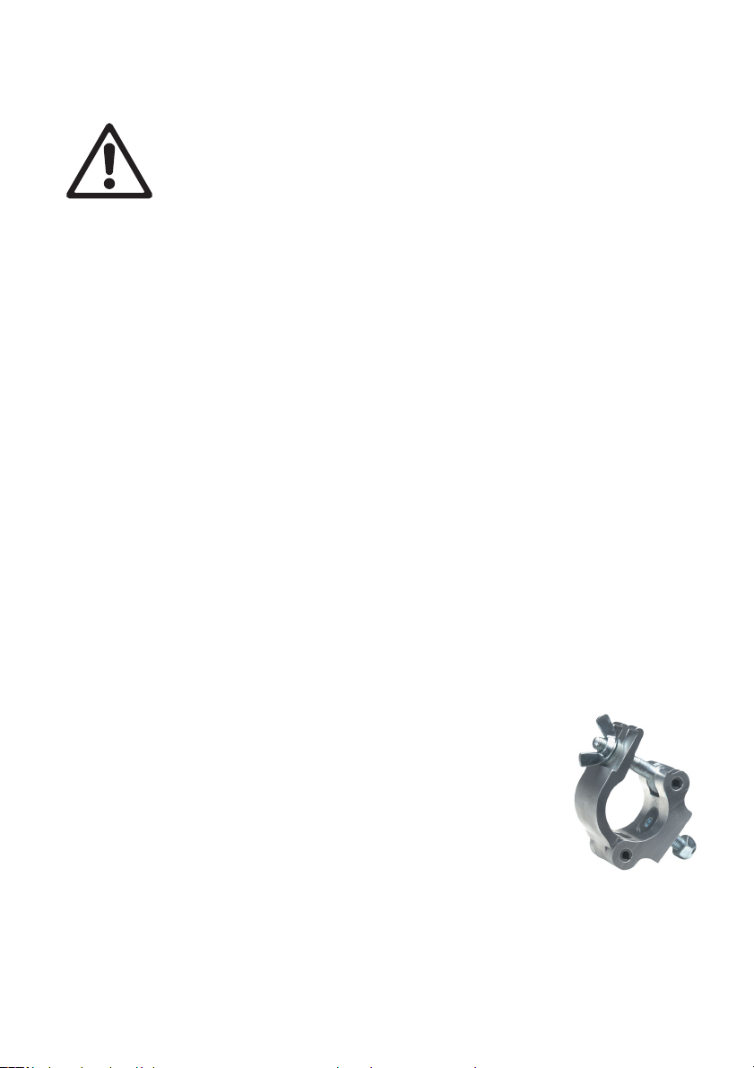
Mounting the fixture on a truss
The fixture can be clamped to a truss or similar rigging
structure in any orientation. When installing the fixture
hanging vertically down, you can use an open-type clamp
such as a G-clamp. When installing in any other orientation,
you must use a closed-type rigging clamp such as halfcoupler clamp (see illustration on right) that completely
encircles the truss chord.
To clamp the fixture to a truss:
1. Check that the rigging structure can support at least 10 times the weight
of all fixtures and equipment to be installed on it.
12 RUSH® MH 11 Beam User Manual
Page 13
2. Block access under the work area.
3. The fixture is supplied with two omega-type brackets to which rigging
clamps can be attached. Check that the rigging clamps are undamaged
and approved for the fixture’s weight. Bolt a rigging clamp securely to
each bracket. The bolts used must be M12, grade 8.8 steel minimum,
and fastened with self-locking nuts.
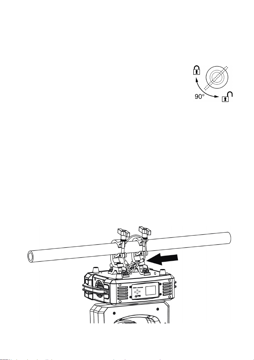
4. Fasten the omega brackets to the base of the fixture
using the brackets’ quarter-turn fasteners. Turn quarterturn fasteners a full 90° to lock them (see illustration on
right).
5. Working from a stable platform, hang the fixture on the truss and fasten
the rigging clamps onto the truss.
6. Secure the fixture with a safety cable as directed below.
7. Check that the head will not collide with other fixtures or objects.
Securing with a safety cable
Secure the fixture with a safety cable (or other secondary attachment) that
is approved for the weight of the fixture so that the safety cable will hold the
fixture if a primary attachment fails.
Loop the safety cable through the eye bracket in the fixture’s baseplate
between the clamps (arrowed in illustration below) and around a secure
anchoring point.
If a safety cable attachment point becomes damaged or deformed, do not
use the fixture. Return it to a Martin Service Centre for repair.
RUSH® MH 11 Beam User Manual 13
Page 14
AC power
Read ‘Safety information’ on page 5 before connecting
the fixture to AC mains power.
Warning! The mains power input cable supplied with the
fixture is rated 9 A and can safely supply only one fixture
with mains power. Do not connect any device to the
fixture’s MAINS OUT socket when using this input cable.
If you want to connect other fixtures to the MAINS OUT
socket, see ‘Linking fixtures to power in a chain’ below.
For protection from electric shock, the fixture must be
grounded (earthed). The power distribution circuit must be
equipped with a fuse or circuit breaker and ground-fault
(earth-fault) protection.
Socket outlets or external power switches used to supply the
fixture with power must be located near the fixture and easily
accessible so that the fixtures can easily be disconnected
from power.
Do not use an external dimming system to supply power to the fixture, as
this may cause damage to the fixture that is not covered by the product
warranty.
The fixture can be hard-wired to a building electrical installation if you want
to install it permanently, or a power plug (not supplied) that is suitable for
the local power outlets can be installed on the power cable.
If you install a power plug on the power cable, install a grounding type
(earthed) plug with integral cable grip that is rated minimum 8 A at a
suitable voltage for your local power system. Follow the plug manufacturer’s
instructions and connect the wires in the power cable as shown in this table:
US system
EU system
The fixture has an auto-ranging power supply that accepts AC mains power
at 100-240 V at 50/60 Hz. Do not apply AC mains power at any other
voltage or frequency to the fixture.
Live or L Neutral or N
Black White Green
Brown Blue Yellow/green
Earth, Ground or
Linking fixtures to power in a chain
The mains power input cable supplied with the fixture is rated 9 A and can
safely supply power to one fixture only. If you want to use the MAINS OUT
socket on the fixture to link power to the next fixture in a daisy-chain, you
14 RUSH® MH 11 Beam User Manual
Page 15

must obtain a 16 A-rated power input cable and 16-A rated power relay
cables available as accessories from Martin® (see ‘Accessories’ on page
44). Using these 16 A-rated cables, you can link:
• Maximum two (2) RUSH® MH 11 Beam fixtures in total at 100-120 V,
or
• Maximum four (4) RUSH® MH 11 Beam fixtures in total at 200-240 V.
If you install a power plug (cord cap) on the 16 A-rated power input cable,
install a grounding type (earthed) plug with integral cable grip that is rated
minimum 16 A at the correct voltage rating for your local power supply.
RUSH® MH 11 Beam User Manual 15
Page 16

Fixture overview
2
1
1 – Display
The display is used to configure the fixture and show status.
2 – Control buttons
• MENU: Press to activate the menu. Within the menu, press to escape
and return to the previous level. Press and hold to exit the menu.
• DOWN: Press to scroll down through menu options.
• UP: Press to scroll up through menu options.
• ENTER: Press to confirm and save the menu selection. Press and hold
to exit the menu.
3 –XLR DMX input/output sockets
For your convenience, 3 and 5-pin XLR sockets are provided for DMX input
and output (through to next fixture). Do not connect output cables to both
the 3-pin and 5-pin output sockets at the same time as this may cause data
errors (in other words, you cannot use the two outputs on the fixture to split
the DMX line).
4 – AC mains power input
A yellow Neutrik True1 PowerCon inlet connector is provided to connect the
fixture to mains power.
5 – AC mains power link output
A yellow Neutrik True1 PowerCon outlet connector is provided to allow
mains power to be linked to the next fixture. Refer to the section above
“Linking fixtures to power in a chain” for safe use of this connector.
6 – Mains fuse
The fixture’s 5T 250 V, 8 A fuse is located in a fuse holder next to the power
input/output connectors.
3 4 5 6
16 RUSH® MH 11 Beam User Manual
Page 17

Control data link
A DMX 512 data link is required in order to control the fixture via DMX. The
fixture has 3-pin and 5-pin XLR connectors for DMX data input and output.
Up to 32 devices can be linked together on a single daisy chain. The total
number of fixtures in one 512-channel DMX universe is limited by the
number of DMX channels required by the fixtures. Note that if independent
control of a fixture is required, it must have its own DMX channels. Fixtures
that are required to behave identically can share the same DMX address
and channels. To add more fixtures or groups of fixtures when the above
limits are reached, add a DMX universe and/or split the daisy-chained link
into branches using a powered DMX splitter.
Tips for reliable data transmission
Use shielded twisted-pair cable designed for RS-485 devices: standard
microphone cable cannot transmit control data reliably over long runs. 24
AWG cable is suitable for runs up to 300 meters (1000 ft.). Heavier gauge
cable and/or an amplifier is recommended for longer runs.
• pin 1 = shield
• pin 2 = cold (-)
• pin 3 = hot (+).
Pins 4 and 5 in the 5-pin XLR connectors are not used in the fixture but are
available for possible additional data signals as required by the DMX512-A
standard. Standard pin-out is pin 4 = data 2 cold (-) and pin 5 = data 2 hot
(+).
RUSH® MH 11 Beam User Manual 17
Page 18

To split the link into branches, use an opto-isolated splitter such as the
Martin® DMX 5.3 Splitter. Terminate the link by installing a termination plug
in the output socket of the last fixture. The termination plug, which is a male
XLR plug with a 120 Ohm, 0.25 watt resistor soldered between pins 2 and
3, “soaks up” the control signal so it does not reflect and cause interference.
If a splitter is used, terminate each branch of the link.
Connecting the data link
To connect the fixture to data:
1. Connect the DMX data output from the controller to the closest fixture’s
male XLR DMX input connector.
2. Connect the first fixture’s DMX output to the DMX input of the next
fixture and continue connecting fixtures output to input.
3. Terminate the last fixture on the link with a DMX termination plug.
18 RUSH® MH 11 Beam User Manual
Page 19

Fixture setup
This section explains the fixture characteristics you can set that determine
how it can be controlled and will behave. You choose the settings using the
menus available from the control panel, and they are retained even when
the fixture is powered off.
Options can also be set over the DMX line using RDM from a suitable
controller, see “Setting options by RDM” on page 24.
A complete map of the control menu structure and brief explanations of their
purposes can be found on page 39. Only the most-used functions are
described in this section.
Using the control menus
To access the control menus, press the MENU button.
Navigate the menu structure using the ENTER, DOWN and UP buttons.
To select a menu option or to confirm a selection, press the ENTER button.
To return to a higher level in the menu structure without making a change,
press the MENU button.
To exit the control menus completely, press and hold the MENU button.
Setting DMX address
Each fixture must be assigned a DMX address. The DMX address, also
known as the start channel, is the first channel used to receive instructions
from a DMX controller. The fixture is controlled using 18 DMX channels. If a
fixture has a DMX address of 1, then it uses channels 1 to 18 inclusive. The
following fixture in the DMX chain can then be set to a DMX address of 19.
For independent control, each fixture must be assigned its own control
channels. Two fixtures of the same type may share the same address if
identical behavior is desired. Address sharing can be useful for diagnostic
purposes and symmetric control, particularly when combined with the
inverse pan and tilt options.
To set the fixture’s DMX address:
1. Enter the control menu and select DMX FUNCTION. Press ENTER.
2. Select DMX ADDRESS and press ENTER.
3. Use the UP and DOWN buttons to select the desired address setting.
4. Press ENTER to confirm your selection.
RUSH® MH 11 Beam User Manual 19
Page 20

Lamp control settings
The fixture’s lamp may be controlled automatically or manually using these
settings. If the lamp is hot from having been previously lit, it will not restrike
until the temperature falls below the MAX ON AT TEMPERATURE, which is
fixed at 45° C (113° F). If the temperature rises above the LAMP OFF
TEMPERATURE, which is 130° C (266° F), then the lamp will shut down.
Switching lamp on or off manually
The lamp can be turned on or off from the control panel:
1. In the LAMP SETTING menu select ON/OFF option and press ENTER.
2. Select ON or OFF and press ENTER.
3. Press ENTER to confirm or press MENU to exit.
Switching on lamp automatically at power-on
Normally the lamp will strike automatically when power is applied to the
fixture. You can disable this feature if you want to:
1. In the LAMP SETTING menu select STATE AT POWER option and
press ENTER.
2. Select ON to enable automatic lamp strike at power up (default), or OFF
to disable it.
3. Press ENTER to confirm or press MENU to exit.
Switching on lamp automatically when DMX is received
The fixture will normally strike its lamp if it receives a DMX signal and the
lamp is off. You can disable this feature:
1. In the LAMP SETTING menu select ON VIA DMX ON and press
ENTER.
2. Select ON to enable automatic lamp on when DMX is received (default)
or OFF to disable it.
3. Press ENTER to confirm or press MENU to exit.
Lamp control via DMX
You can remotely turn the lamp off and on using a DMX controller. This
feature can be disabled if you want:
1. In the LAMP SETTING menu select OFF VIA DMX and press ENTER.
2. Select ON to enable remote lamp control (default) or OFF to disable it.
3. Press ENTER to confirm or press MENU to exit.
20 RUSH® MH 11 Beam User Manual
Page 21

Fixture settings
Hold or blackout on loss of DMX
If the fixture loses the DMX signal, it can either hold the look it’s currently
displaying or black out. The default is HOLD. To change the setting:
To set fixture behavior when it is not receiving DMX:
1. In the FIXTURE SET menu select LOSS OF DMX and press ENTER.
2. Select BLACK OUT or HOLD (default).
3. Press ENTER to confirm or press MENU to exit.
Inverting pan and tilt
You can reverse DMX pan or tilt control to provide mirror image movements
or to correct for a fixture being rigged the wrong way round. The default
setting is OFF. To reverse pan or tilt control:
1. In the FIXTURE SET menu select STATUS SETTINGS and press
ENTER.
2. Select PAN INVERSE or TILT INVERSE and press ENTER.
3. Select ON to reverse control, or OFF for normal control (default).
4. Press ENTER to confirm or press MENU to exit.
Pan/tilt correction when knocked
Normally if the fixture is knocked or pushed while set to a position it will
automatically return to the correct position. You can turn this feature off:
1. In the FIXTURE SET menu select STATUS SETTINGS and press
ENTER.
2. Select P/T FEEDBACK and press ENTER.
3. Select OFF to disable automatic position correction or ON to enable the
function (default).
4. Press ENTER to confirm or press MENU to exit.
Low power mode on loss of DMX (hibernation)
If DMX is lost, after 15 minutes the fixture turns off the lamp and goes into
low power mode. The fixture automatically resets and returns to full power
when DMX is restored. You can disable this feature or change the delay:
1. In the FIXTURE SET menu select STATUS SETTINGS and press
ENTER.
2. Select HIBERNATION and press ENTER.
3. Select OFF (default) to disable hibernation. To enable hibernation,
select a delay time of 1 to 99 minutes.
4. Press ENTER to confirm or press MENU to exit.
RUSH® MH 11 Beam User Manual 21
Page 22

Blackout during pan/tilt movements
The fixture can be set to black out during pan or tilt movement. To enable
this option:
1. In the FIXTURE SET menu select BI.O.P/T MOVE and press ENTER.
2. Select ON to enable automatic blackout, or OFF to disable it (default).
3. Press ENTER to confirm or press MENU to exit.
Blackout during color/gobo change
The fixture can be set to black out during pan or tilt movement. To enable
this option:
1. In the FIXTURE SET menu select BI.O.OTHER MOVE and press
ENTER.
2. Select ON to enable automatic blackout, or OFF to disable it (default).
3. Press ENTER to confirm or press MENU to exit.
Display backlight auto-dim
The LCD control display automatically dims 5 minutes after the last key
press, but you can change the delay time:
1. In the FIXTURE SET menu select DISPLAY SETTING and press
ENTER.
2. Select BACKLIGHT AUTO and press ENTER.
3. Select a delay from 2 to 60 minutes (default 5 minutes).
4. Press ENTER to confirm or press MENU to exit.
Clear error messages from display
If the fixture detects a fault it will display an error message on the display.
You can clear these messages but you must first enter a password which is
“050”. To enter the password and clear the messages:
1. In the FIXTURE SET menu, select SERVICE SETTING and press
ENTER.
2. Select PASSWORD and press ENTER.
3. Use the UP and DOWN buttons to select PASSWORD=050 and press
ENTER.
4. Select CLEAR ERR. INFO and press ENTER.
5. Select YES to clear the error codes, or NO to keep them.
6. Press ENTER to confirm or press MENU to exit.
Restore to factory settings
To restore all settings to factory defaults:
1. In the FIXTURE SET menu select FACTORY SETTINGS and press
ENTER
22 RUSH® MH 11 Beam User Manual
Page 23

2. Select YES to restore factory settings.
3. Press ENTER to confirm or MENU to exit without restoring.
Fixture information
Total operating hours
To display the fixture’s total operating hours:
1. In the INFORMATION menu, select TIME INFORMATION and press
ENTER.
2. Select TOTAL USE TIME and press ENTER.
3. The total operating time of the fixture is displayed in hours.
4. Press MENU to exit.
Viewing and resetting Lamp on hours
To display the number of hours the lamp has run:
1. In the INFORMATION menu, select TIME INFORMATION and press
ENTER.
2. Select LAMP ON HOURS and press ENTER.
3. The total on time of the lamp is displayed in hours.
To reset lamp hours after installing a new lamp:
1. In the INFORMATION menu, select TIME INFORMATION and press
ENTER.
2. Select RESET LAMP TIME and press ENTER.
3. At the PASSWORD prompt, scroll to “038” using the UP/DOWN buttons
and press ENTER.
4. Select YES (or NO to abandon reset).
5. Press ENTER to confirm or press MENU to exit.
Head Temperature
To display the temperature inside the head:
1. In the INFORMATION menu, select HEAD TEMPERATURE and press
ENTER.
2. The temperature is displayed. You can select Celsius or Farenheit in
the FIXTURE SET / DISPLAY SETTING / TEMPERATURE UNIT
option.
3. Press MENU to exit.
Displaying software version
To display the version of firmware installed on each circuit board:
RUSH® MH 11 Beam User Manual 23
Page 24

1. In the INFORMATION menu, select SOFTWARE VERSION and press
ENTER.
2. The firmware for each board is displayed.
3. Press MENU to exit.
Position calibration
If an effect does not reset to its home position, you can recalibrate it using a
position offset. To enter an offset:
1. Enter the control menu and select OFFSETTING. Press ENTER.
2. At the CALIBRATION PASSWORD prompt, scroll to 050 using the
UP/DOWN buttons and press ENTER.
3. Select an effect to adjust and press ENTER.
4. Use the UP/DOWN buttons to increase or decrease the offset value.
When the effect reaches the correct position, press ENTER.
5. Press MENU to exit.
Setting options by RDM
You can remotely configure the fixture over the DMX line using RDM.
Martin® offers a range of suitable RDM-compatible controllers.
Martin® M-PC is a Windows-based application available from Martin® that
lets you set up, manage and control a lighting installation from a PC that is
connected to the installation via a DMX data link. To use Martin® M-PC,
connect a PC running the application to the data link via a USB-to-DMX
interface box such as the Martin® M-DMX.
A full list of the RDM functions that the MH 11 fixture supports is given at
the end of this chapter. These functions are generally referred to using the
more specific term ‘PIDs’ or ‘Parameter IDs’.
Scanning for RDM devices on the data link
Before you can communicate with fixtures using RDM, you must send a
scan command (also called a device discovery command) to all the devices
on the data link so that the RDM controller can identify them. It does this by
retrieving each device’s factory-set unique identifier (UID). This process can
take some time depending on the number of devices on the link.
To identify the fixtures on the link:
1. Check that the fixtures are correctly connected to the RDM controller on
the data link and that power is applied to all fixtures.
2. In Martin® M-PC, go to RDM CONTROLLER DISCOVER DEVICES.
24 RUSH® MH 11 Beam User Manual
Page 25

3. Give the controller time to identify the devices on the link and prepare
for communication with the devices.
Getting status and setting options by RDM
The status and options listed in the table below can be read and set by
RDM.
You can set an option on one fixture by sending a unicast RDM command
to that one fixture only, or you can set the same option on all the fixtures on
the data link by sending a broadcast RDM command to all the devices on
the link.
For status reading, you can only use unicast RDM to read information from
an individual fixture.
RDM functions
As a minimum, MH 11 supports the following RDM functions:
Device discovery
DISC_UNIQUE_BRANCH
DISC_MUTE
DISC_UN_MUTE
Device management
GET SET
DEVICE_INFO
IDENTIFY_DEVICE
DMX_START_ADDRESS
SOFTWARE_VERSION_LABEL
SUPPORTED_PARAMETERS
PARAMETER_DESCRIPTION
COMMS_STATUS
QUEUED_MESSAGE
STATUS_MESSAGES
RUSH® MH 11 Beam User Manual 25
Page 26

STATUS_ID_DESCRIPTION
CLEAR_STATUS_ID
DEVICE_MODEL_DESCRIPTION
MANUFACTURER_LABEL
DEVICE_LABEL
FACTORY_DEFAULTS
DMX_PERSONALITY
DMX_PERSONALITY_DESCRIPTION
SENSOR_DEFINITION
SENSOR_VALUE
DEVICE_HOURS
LAMP_HOURS
BOOT_SOFTWARE_VERSION_ID
BOOT_SOFTWARE_VERSION_LABEL
LAST_STATE
DIMMER_CURVE
LAMP_STRIKE
LAMP_STATE
DEVICE_POWER_CYCLES
DISPLAY_INVERT
SLOT_DESCRIPTION
PAN_INVERT
TILT_INVERT
RESET_DEVICE
26 RUSH® MH 11 Beam User Manual
Page 27

Effects
This section describes the effects provided by the RUSH® MH 11 Beam.
See ‘DMX protocol’ on page 35 for a full list of the DMX channels and
values required to control the different effects.
D
imming
Overall intensity can be precisely adjusted from 0 to 100% using 16-bit
coarse and fine control.
Strobe effects
A mechanical shutter provides instant open and blackout, random and
variable speed flash from 1 to 12 flashes per second, and pulse effects.
Pan and tilt
The fixture’s head can be panned through 540° and tilted through 260° with
16-bit coarse and fine control. Using the control menus it is possible to
invert pan or tilt movement. A position feedback circuit provides automatic
position correction if the fixture is knocked out of position.
Light output can be set to black out when the head moves using either the
Auto-blackout = ON command on DMX channel 18, or the BI.O.P/T Move
personality setting in the control menu.
Colors
The color wheel provides the 13 colors listed below plus an open position.
Colors can be selected in full position steps or continuously scrolled to give
split colors. The wheel can be rotated at varying speeds, both clockwise and
counter-clockwise, or display random colors at slow, medium and fast
speeds.
Slot 1: red
Slot 2: blue
Slot 3: green
Slot 4: Rose
Slot 5: yellow
Slot 6: cyan
Slot 7: pink
Slot 8: orange
Slot 9: aqua
Slot 10: purple
Slot 11: CTO
Slot 12: CTB
Slot 13: UV
RUSH® MH 11 Beam User Manual 27
Page 28

Gobos
The fixture contains one gobo wheel with gobo positions as shown below:
Gobo wheel (rotating gobos)
Individual gobos can be set to indexed positions, and rotated clockwise and
counter-clockwise. Gobo shake is also available.
When BI.O. Other Move is ON, the fixture blacks out during color and gobo
changes.
Prism
The fixture incorporates an eight-facet circular prism which can be inserted
into the beam for split effects. The prism can be set to an indexed position
or rotated clockwise or counter-clockwise.
Focus
A motorized focus lens provides 16-bit coarse and fine adjustment of gobo
image sharpness.
Frost
A frost filter can be inserted into the beam for a soft, diffuse wash effect.
28 RUSH® MH 11 Beam User Manual
Page 29

Maintenance
Warning! Read ‘Safety information’ on page 5 before
servicing the fixture.
Disconnect the fixture from mains power before cleaning or
servicing.
Service fixtures in an area where there is no risk of injury
from failing parts, tools or other materials.
The user may carry out the service operations described in this manual. All
other service operations must be carried out by an authorized Martin®
service technician. Do not try to repair the fixture yourself, as you may
create a safety risk or cause damage that is not covered by the product
warranty.
Installation, on-site service and maintenance can be provided worldwide by
the Martin Professional™ Global Service organization and its approved
agents, giving owners access to Martin’s expertise and product knowledge
in a partnership that will ensure the highest level of performance throughout
the product’s lifetime. Please contact Martin® for details.
Cleaning
Excessive dust, smoke fluid, and particle buildup degrades performance,
causes overheating and will damage the fixture. Damage caused by
inadequate cleaning or maintenance is not covered by the product warranty.
The cleaning of external optical lenses must be carried out periodically to
optimize light output. Cleaning schedules for lighting fixtures vary greatly
depending on the operating environment. It is therefore impossible to
specify precise cleaning intervals for the fixture. Environmental factors that
may result in a need for frequent cleaning include:
• Use of smoke or fog machines.
• High airflow rates (near air conditioning vents, for example).
• Presence of cigarette smoke.
• Airborne dust (from stage effects, building structures and fittings or the
natural environment at outdoor events, for example).
If one or more of these factors is present, inspect fixtures within their first
100 hours of operation to see whether cleaning is necessary. Check again
at frequent intervals. This procedure will allow you to assess cleaning
requirements in your particular situation. If in doubt, consult your Martin
dealer about a suitable maintenance schedule.
RUSH® MH 11 Beam User Manual 29
Page 30

Use gentle pressure only when cleaning, and work in a clean, well-lit area.
Do not use any product that contains solvents or abrasives, as these can
cause surface damage.
To clean the fixture:
1. Disconnect the fixture from power and allow it to cool for at least 10
minutes.
2. Vacuum or gently blow away dust and loose particles from the outside
of the fixture and the air vents at the back and sides of the head and in
the base with low-pressure compressed air.
3. Clean surfaces by wiping gently with a soft, clean lint-free cloth
moistened with a weak detergent solution. Do not rub glass surfaces
hard: lift particles off with a soft repeated press. Dry with a soft, clean,
lint-free cloth or low-pressure compressed air. Remove stuck particles
with an unscented tissue or cotton swab moistened with glass cleaner
or distilled water.
4. Check that the fixture is dry before reapplying power.
Replacing gobos
The rotating gobos can be replaced with custom gobos that match the
quality and specifications of the gobos supplied with the fixture (see
‘Interchangeable Gobos’ on page 43).
Optical components have fragile coatings and are exposed to very high
temperatures. Handle and store components with care. Wear cotton gloves
while handling them. Keep them perfectly clean and free of oil and grease to
reduce the risk of heat damage.
To replace a rotating gobo:
1. Disconnect the fixture from power and
allow it to cool for at least 10 minutes.
2. See illustration to right. Loosen the
screws indicated with a TX20 TORX
screwdriver and remove the head shell.
30 RUSH® MH 11 Beam User Manual
Page 31

3. The rotating gobos sit in goboholders that slot into clips in the rotating
gobo wheel. Find the gobo you want to replace. See below. Pull its
goboholder away from the gobo wheel slightly, then lift the goboholder
out of its clip in the wheel.
4. The gobo is held by a retaining spring. Use a flat-bladed screwdriver or
tweezers to lever the end of the spring out of its slot, then lift out the
spring.
5. Remove spring, retaining ring and gobo.
RUSH® MH 11 Beam User Manual 31
Page 32

6. Insert the new gobo in the holder. Insert the retaining ring, making sure
the tab fits in the goboholder slot.
7. Replace the retaining spring with the narrow end in, against the ring.
Make sure the outside end of the spring is held firmly in place in its slot
in the goboholder.
8. Slide the tab on the goboholder under the clip on the gobowheel and
make sure that the teeth on the goboholder engage the gobo wheel
correctly.
9. Replace the head cover and be ready for the head to move when you
reapply power.
Lamp replacement
Warning! Wear safety glasses and gloves when handling
lamps.
Allow the fixture to cool for at least 2 hours before handling a
lamp.
To avoid the risk of a discharge lamp exploding in the fixture,
replace the lamp when it reaches its specified lifetime (see
Lamp on page 42).
Install only lamps that are approved by Martin® for this fixture
(see Lamp on page 42).
If a lamp breaks, ventilate the room for 30 minutes, put on nitrile gloves and
remove the pieces . Put the pieces in a sealed plastic bag and take them to
your local waste facilities for specialist recycling. Do not use a vacuum
cleaner to clean up pieces of a broken lamp.
The lamp must be perfectly clean and totally free of oil and grease. Never
touch the lamp with bare hands. If you contaminate the lamp, clean it with
an alcohol wipe and then dry it with a lint-free cloth.
To replace the lamp:
1. Disconnect the fixture from power and allow it to cool for one hour.
2. Remove the lamp cover using a TX10 TORX screwdriver.
32 RUSH® MH 11 Beam User Manual
Page 33

3. Squeeze and unhook the ends of the lamp retaining spring. Pivot the
spring away from the lamp.
4. Carefully pull the lamp wires off the connection pins. Remove the lamp.
5. Avoid direct contact with the new lamp. Either wear clean lint-free cotton
gloves or hold the lamp with the included cloth. Remove the new lamp
from its packaging and attach the wires to the connection pins.
RUSH® MH 11 Beam User Manual 33
Page 34

6. With the connection pins pointing to the left, away from the retaining
spring, seat the new lamp in the fixture. Secure the lamp with the
retaining spring.
7. Reinstall the lamp cover before applying power.
8. Reset the lamp hours counter as described on page 23.
Lamp temperature control
The lamp temperature is monitored to check for high temperatures caused
by fan failure or blockage. If the lamp sensor reaches the LAMP OFF
TEMPERATURE, which is fixed at 130° C (266° F), for more than 5 minutes
then the lamp shuts down automatically. The lamp will restrike automatically
when the temperature cools to the MAX ON AT TEMPERATURE, which is
fixed at 45° C (113° F).
Replacing the primary fuse
If the fixture is completely dead, the fixture’s primary fuse may have blown
and it may be necessary to install a new fuse. Replace with a fuse of the
same size and specified rating only.
If you need to replace the fuse:
1. Disconnect the fixture from power and allow it to cool.
2. Unscrew the cap of the fuse holder (shown on page 16) and remove the
fuse.
3. Replace with a fuse of the same size and rating only.
4. Screw the fuse holder cap back on before reapplying power.
Updating firmware
If Martin releases an updated version of firmware for this fixture, you can
update it using the Martin Companion Software using M-DMX. See
www.martin.com.
Service and repairs
Never try to repair the fixture by yourself as this may result in damage or
malfunction and it may potentially void your product warranty. The
equipment must only be serviced or repaired by an authorized Martin
service technician.
34 RUSH® MH 11 Beam User Manual
Page 35

DMX protocol
r
Channel Value Function
1
2
0-255 Intensity 0 → 100%
0-255 Dimmer intensity fine
0-31 Shutter closed
32-63 Shutter open
64-95 Strobe effect slow → fast
3
96-127 Pulse, fast close & slow open
128-159 Pulse, fast open & slow close
160-191 Sequential pulse effects
192-223 Random strobe effect slow → fast
224-255 Shutter open
4
0 Open
1-11 Open → Red
12 Red (Color 1)
13-22 Red → Blue
23 Blue (Color 2)
24-32 Blue → Green
33 Green (Color 3)
34-42 Green → Magenta
43 Magenta (Color 4)
44-52 Magenta → Yellow
53 Yellow (Color 5)
54-62 Yellow → Light blue
63 Light blue (Color 6)
64-73 Light blue → Pink
74 Pink (Color 7)
75-84 Pink → Orange
85 Orange (Color 8)
86-95 Orange → Aqua
96 Aqua (Color 9 )
97-105 Aqua → Purple
106 Purple (Color 10)
107-114 Purple → CTO
115 CTO (Color 11)
116-124 CTO → CTB
125 CTB (Color 12)
126-136 CTB → UV
137 UV (Color 13)
138-146 UV → Open
Dimmer, coarse
Dimmer, fine
Shutte
Color Wheel
Continuous Scroll
Fade
type
Default
value
Fade 0
Fade 0
Snap 50
Snap 0
RUSH® MH 11 Beam User Manual 35
Page 36

Channel Value Function
147 Open
Stepped Scroll
148-151 Red
152-155 Blue
156-159 Green
160163 Magenta
164-167 Yellow
168-171 Light blue
172-175 Pink
176-179 Orange
180-183 Aqua
184-187 Purple
188-191 CTO
192-195 CTB
196-199 UV
Continuous rotation
200-220 Clockwise, fast → slow
221-222 No rotation
223-243 Counterclockwise, slow → fast
244 -
247
248 -
251
252 -
255
5
0-11 Open
12-23 Beam Smoother
24-29 Gobo 1, indexed
30-35 Gobo 2, indexed
36-41 Gobo 3, indexed
42-47 Gobo 4, indexed
48-53 Gobo 5, indexed
54-59 Gobo 6, indexed
60-65 Gobo 7, indexed
66-71 Gobo 8, indexed
72-76 Gobo 1, rotating
77-81 Gobo 2, rotating
82-86 Gobo 3, rotating
87-91 Gobo 4, rotating
92-96 Gobo 5, rotating
Random colors
Fast
Medium
Slow
Rotating Gobos: Function and
Selection
Gobo indexing, set position on ch. 6
Gobo rotation, set speed and direction
on ch. 6
Fade
type
Default
value
Snap 0
36 RUSH® MH 11 Beam User Manual
Page 37

Channel Value Function
97-101 Gobo 6, rotating
102-106 Gobo 7, rotating
107-111 Gobo 8, rotating
Rotating gobo shake
112-121 Gobo 1, shake
122-131 Gobo 2, shake
132-141 Gobo 3, shake
142-151 Gobo 4, shake
152-161 Gobo 5, shake
162171 Gobo 6, shake
172-181 Gobo 7, shake
182-191 Gobo 8, shake
Gobo wheel 1 rotation
192-223 Clockwise rotation, fast → slow
224-255 Counterclockwise rotation, slow → fast
Rotating Gobos: Indexing and Speed
If indexed gobo selected on ch. 5
0-255 Gobo angle, coarse, 0°-360°
6
0-31 No rotation (0º)
32-93 Clockwise gobo rotation, fast → slow
If rotating gobo selected on ch. 5
94-127 No rotation
128-189
Counterclockwise gobo rotation, slow →
fast
190-255 No rotation (90º)
7
0-255 Gobo angle, fine
Rotating Gobos: Fine Indexing
Rotating Prisms: Function and
Selection
0-31 Open (no prism)
8
32-127 4-facet prism, indexed
Prism indexing, set angle on ch. 9
Prism rotation, set speed and direction
on ch. 9
128-255 4-facet prism, rotating
Rotating Prisms: Indexing and Speed
When indexed prism selected on ch. 9
0-255 Prism angle, coarse, 0° → 360°
9
0-31 No rotation (0º)
When rotating prism selected on ch. 9
32-93 Clockwise rotation, fast → slow
94-127 No rotation
128-189 Counterclockwise rotation, slow → fast
190-255 No rotation (90º)
Fade
type
Default
value
Fade 128
Fade 0
Snap 0
Fade 128
RUSH® MH 11 Beam User Manual 37
Page 38

10
11
12
13
14
15
16
17
18
0-255 Indexed prism, fine control
Frost (Wash Mode)
128-255 Enable frost
0-255 Focus, near → far
0-255 Fine focus adjustment
0-255 Pan, 0° → 540°
0-255 Pan, fine control
0-255 Tilt, 0° → 270°
0-255 Tilt, fine control
0-19 Reserved (no function)
20-29 Auto-Blackout ON
30-39 Auto-Blackout OFF (default)
40-59 Lamp ON (hold for 8s)
60-79 Lamp OFF (hold for 8s)
80-84 Reset all (hold for 3s)
85-87 Pan/tilt reset (hold for 3s)
88-90 Reset color wheel (hold for 3s)
91-93 Reset gobos (hold for 3s)
94-96 Reset shutter (hold for 3s)
97-99 Reset other effects (hold for 3s)
100-104 Control panel display ON (hold for 3s)
105-109 Control panel display OFF(hold for 3s)
110-115 Parameter shortcuts ON (default)
116-121 Parameter shortcuts OFF
122-255 Reserved (no function)
Rotating Prism: Fine Indexing
Focus, Coarse
Focus, Fine
Pan, Coarse
Pan, Fine
Tilt, Coarse
Tilt, Fine
Lamp On/Off, Reset, Personality
Settings
Fade 0
Snap 0 0-127 No frost
Fade 128
Fade 0
Fade 128
Fade 0
Fade 128
Fade 0
Snap 0
38 RUSH® MH 11 Beam User Manual
Page 39

Control menus
A
A
To access the control menus, press the MENU button. Use the UP and
DOWN buttons to navigate the menus. Select a menu option with the
ENTER button. For more information, see ‘Using the control menus’ on
page 19.
Default fixture settings are shown in bold.
Menu Sub-menu Setting/Value Explanation
DMX Address 001-492 Fixture DMX address setting
DMX Value PAN…
DMX Function
Total Use Time XXXX(Hours) Fixture running time in hours
Lamp On Hours XXXX(Hours) Lamp hours (resettable)
Time Information
Head
Temperature
Fan Info
Information
Encode Feedback
Software Version
On/Off ON/OFF Manually switch lamp on/off
State at Power ON/OFF Enable lamp on at power on
On via DMX On ON/OFF Enable lamp on via DMX
Off via DMX ON/OFF Enable lamp off via DMX
Max On at Temp. 45° C (113° F)
Lamp Setting
Lamp Off Temp. 130° C (266° F)
Loss of DMX Black out /Hold Black out/Hold @ DMX loss
Status Settings
Fixture Set
BI.O.P/T Move
BI.O.Other Move
LampTime
Password
Reset Lamp Time YES/NO Reset lamp hours counter
XXX °C/°F
2U_FAN1 :XXX RPM
2U_FAN2 :XXX RPM
…………
PAN ENCODE:
TILT ENCODE:
1U01……V1.4.0
2U01……V1.4.0
…….
Pan inverse ON/OFF Reverse pan control
Tilt inverse ON/OFF Reverse tilt control
P/T Feedback ON/OFF Toggle pan/tilt correction
Hibernation OFF, 01M~99M Set timing for standby mode
ON/OFF
ON/OFF Blackout during color/gobo
XXX
Displays DMX level of each
channel
Enter password 038 to reset
lamp hours
Displays head temperature in
°C or °F
Displays speed of each fan.
Feedback encoder level
Displays software version of
each PCB
utomatic lamp restart
temperature (fixed setting)
utomatic lamp off
temperature (fixed setting)
Blackout during pan or tilt
change
RUSH® MH 11 Beam User Manual 39
Page 40

Menu Sub-menu Setting/Value Explanation
A
Display Setting
Fixture Set
Service Setting
Factory settings YES/NO
Reset All
Reset Pan&Tilt
Reset Colors
Reset Gobos
Reset Shutter
Reset Function
Reset Others
Auto Test
Manual Control
Fixture Test
Calibration
Password
Pan=-128..127
Tilt=-128..127
Offsetting
Color1=-128..127
:
Display inverse
Backlight auto 02~60m 05m Set delay time for display off
Temperature Unit
Display Warning
Password Password=XXX
RDM UID
Clear Err. Info
PAN =XXX
:
0..255
0..255
0..255
:
UTO/ON/OFF Flip display
Celsius/
Fahrenheit
Error Record 1
Error Record 2
... ...
XXXXXX RDM UID
YES/NO Clear Err. Info
Select unit for temp. display
Toggle error code display
Enter password to clear error
codes
Reset fixture personalities to
factory default values
Perform a reset of selected
effect(s)
Perform automatic test of all
functions
Manually test each function
Enter password to access
offset menu
Enter offset value to achieve
home / open position
40 RUSH® MH 11 Beam User Manual
Page 41

Troubleshooting
This section describes a few common problems that may occur during
operation and provides some suggestions for easy troubleshooting:
Symptom Potential Causes Remedies
No light from
fixture, or fans not
working.
One of the control
channels is
unresponsive or
only responds
intermittently.
Fixture does not
respond to DMX
control.
Power supply issue
such as blown fuse,
faulty connector or
damaged cable.
DMX setup or DMX link
fault.
Damaged step motor or
cable connection
between head and
body.
Fault in the DMX
network due to
connector or cable
damage, incorrect DMX
addressing, or potential
interference from
proximity to a high
voltage installation.
Ensure that the mains
supply is connected and
supplying power to the
fixture.
Check all power
connections and cables.
Check and if necessary
replace the fixture fuse.
See next section.
Contact your Martin
authorized distributor or
service center for
assistance.
Ensure that fixture’s DMX
address matches address
set on DMX control
device.
Check that fixture DMX
LED is on, and if not,
check all DMX cables and
connections.
Ensure that DMX link is
terminated.
Check that all
components on DMX link
use standard DMX
polarity.
Attempt to control the
fixture with another DMX
control device.
Move or shield link if it is
close to an unshielded
high-voltage installation.
RUSH® MH 11 Beam User Manual 41
Page 42

Specifications
Physical
Dimensions (LxWxH) ................... 301 x 408 x 560 mm (11.9 x 16.1 x 22.1 in.)
Weight .................................................................................. 19.3 kg (42.5 lbs.)
Lamp
Approved lamp ............................................ Philips MSD Platinum 11R 250 W
Color temperature ................................................................................. 7800 K
Average lifetime* ............................................................................. 2000 hours
*Preliminary figure obtained under manufacturer´s test conditions
Dynamic Effects
Dimming ......................................................... 0 – 100%, coarse & fine control
Shutter ................................ Strobe & pulse effects, instant open and blackout
Color wheel ........................................... 10 colors plus CTO, CTB, UV & open
Rotating gobo wheel ................................. 8 gobos plus open, 16-bit indexing,
continuous rotation and shake
Prism ................................................ 8 facet, 16-bit indexing, variable rotation
Frost ....................................................................................... motorized, on/off
Focus .................................................... Motorized, 16-bit coarse & fine control
Pan ................................ 540°, 16-bit coarse & fine control, position correction
Tilt ................................. 260°, 16-bit coarse & fine control, position correction
42 RUSH® MH 11 Beam User Manual
Page 43

Optics
Beam angle .............................................................................................. 2.6°
Interchangeable Gobos
Acceptable materials ............................................ Stainless steel or aluminum
Diameter ....................................... 14 mm, +0/-0.2 mm (0.55 in., +0/-0.008 in.)
Max. image diameter, metal .................................................. 9.5 mm (0.37 in.)
Thickness, metal ..................................................... 0.2mm (0.008 in.) nominal
Control and Programming
Control systems .............................................................................. DMX, RDM
DMX channels ............................................................................................... 18
Integrated user interface ...................... Control panel with backlit LCD display
DMX compliance ............................................................ USITT DMX512/1990
RDM compliance ................................................................. ANSI/ESTA E.120
Construction
Color ......................................................................................................... Black
Housing .......................................... High impact flame retardant thermoplastic
IP rating .................................................................................................... IP 20
Installation
Mounting points .......................... Two quarter-turn brackets for rigging clamps
Location ................ Dry location only, must be fastened to surface or structure
Orientation ................................................................................................... Any
Minimum distance to illuminated surfaces .................................... 10 m (33 ft.)
Minimum distance to combustible materials ................................. 20 cm (8 in.)
Minimum clearance around fans and vents ................................ 50 cm (20 in.)
Connections
AC power input/output ............................................ Neutrik PowerCon TRUE1
DMX & RDM data in/out ........................................... 3-pin & 5-pin locking XLR
Electrical
AC power ............................................................ 100-240 V nominal, 50/60 Hz
Typical half-cycle RMS inrush current ....................................................... 16A
Power supply unit ................................... Auto-ranging electronic switch mode
Fuse .......................................................................................... 5T 250 V 8.0 A
Typical power and current
90 V, 60 Hz .................................................................... 350 W, 3.9 A, PF 0.99
120 V, 60 Hz .................................................................. 345 W, 2.9 A, PF 0.98
230 V, 50 Hz .................................................................. 342 W, 1.5 A, PF 0.97
264 V, 50 Hz .................................................................. 340 W, 1.3 A, PF 0.97
Measurements made at nominal voltage. Figures are typical, not
maximum, allow for a deviation of +/- 10%.
RUSH® MH 11 Beam User Manual 43
Page 44

Thermal
Cooling ........................................................Forced air, temperature-regulated
Maximum ambient temperature (T
Minimum ambient temperature (T
max.) ................................ 40° C (104° F)
a
min) ......................................... 0°C (32° F)
a
Total heat dissipation* ................................................................. 1430 BTU/hr.
*Calculated, +/- 10%, at full intensity, full white
Approvals
EU safety ....................... EN 60598-2-17 (EN 60598-1), EN 62471, EN 62493
EU EMC................................................ EN 55015; EN 55032; EN 55103-1,-2;
EN 61000-3-2,-3; EN 61000-4-2, -4, -5; EN 61547
US safety ............................................................................................. UL 1573
US EMC.............................................................. CFR Title 47 Part 15 Class A
Canadian safety ................................................................ CSA C22.2 No. 166
Canadian EMC .................................................................... ICES-003 Class A
Australia/NZ .............................................................................. RCM (Pending)
Included Items
Power cable, 1.5 m (4.9 ft.) without mains plug
Two omega-type clamp attachment brackets with quarter-turn fasteners
Accessories
Installation hardware
Half-coupler clamp .....................................................................P/N 91602005
G-clamp* ....................................................................................P/N 91602003
Quick-trigger clamp* ...................................................................P/N 91602007
Safety cable, safe working load 60 kg, black .............................P/N 91604006
Safety cable, safe working load 60 kg, silver .............................P/N 91604007
*Use with fixture hanging vertically downwards only
Input cables, 16 A, for connection to power
Power Input Cable, H07RN-F, 2.5 mm
Neutrik TRUE1 NAC3FX-W to bare ends, 1.5 m (4.9 ft.) .....P/N 91611797
Power Input Cable, H07RN-F, 2.5 mm
2
, 14 AWG,
2
, 14 AWG,
Neutrik TRUE1 NAC3FX-W to bare ends, 5 m (16.4 ft.) ......P/N 91611786
Power Input Cable, SJOOW, AWG 12,
Neutrik TRUE1 NAC3FX-W to bare ends, 1.5 m (4.9 ft.) .....P/N 91610173
Power Input Cable, SJOOW, AWG 12,
Neutrik TRUE1 NAC3FX-W to bare ends, 5 m (16.4 ft.) ......P/N 91610174
44 RUSH® MH 11 Beam User Manual
Page 45

Relay cables, 16 A, for relaying power in chains
Power Relay Cable, H07RN-F, 2.5 mm
Neutrik TRUE1 to TRUE1, 0.45 m (1.5 ft.)............................ P/N 91611784
Power Relay Cable, H07RN-F, 2.5 mm
Neutrik TRUE1 to TRUE1 1.2 m (3.9 ft.) ............................... P/N 91611785
Power Relay Cable, H07RN-F, 2.5 mm
2
,
2
,
2
,
Neutrik TRUE1 to TRUE1 2.5 m (8.2 ft.) ............................... P/N 91611796
Power Relay Cable, SJOOW, AWG 12,
Neutrik TRUE1 to TRUE1, 0.45 m (1.5 ft.)............................ P/N 91610170
Power Relay Cable, SJOOW, AWG 12,
Neutrik TRUE1 to TRUE1, 1.2 m (3.9 ft.).............................. P/N 91610171
Power Relay Cable, SJOOW, AWG 12,
Neutrik TRUE1 to TRUE1, 2.5 m (8.2 ft.).............................. P/N 91610172
Power connectors, cable mount
Neutrik PowerCON TRUE1 NAC3MX-W (male) ........................ P/N 91611788
Neutrik PowerCON TRUE1 NAC3FX-W (female) ...................... P/N 91611789
Related Items
RUSH® Software Uploader 2 M-DMX with MartinCompanion uploader
software (see www.martin.com)
Ordering Information
RUSH® MH 11 Beam in cardboard box .................................... P/N 90280110
Specifications subject to change without notice. For latest product
specifications, see www.martin.com
Disposing of this product
Martin® products are supplied in compliance with Directive
2012/19/EC of the European Parliament and of the Council of
the European Union on WEEE (Waste Electrical and
Electronic Equipment), where applicable. Help preserve the
environment! Ensure that this product is recycled at the end of
its life. Your supplier can give details of local arrangements for
the disposal of Martin products
RUSH® MH 11 Beam User Manual 45
Page 46

Photobiological Safety Warning
The label shown below is displayed on this product. If it becomes difficult or
impossible to read, it must be replaced using the illustration below to
reproduce a new label sized 88 x 43, in black on a yellow background.
RISK GROUP 3
WARNING. UV emitted from this product.
Avoid eye or skin exposure to unshielded
product.
WARNING. Possibly hazardous optical
radiation emitted from this product. Do not look
at operating lamp. Eye injury may result.
46 RUSH® MH 11 Beam User Manual
Page 47

Page 48

 Loading...