

Page 1
MAC Viper Performance™
USER GUIDE
Page 2

© 2012-2013 Martin Professional. Information subject to change without notice. Martin Professional and all affiliated companies dis-
claim liability for any injury, damage, direct or indirect loss, consequential or economic loss or any other loss occasioned by the use
of, inability to use or reliance on the information contained in this document. The Martin logo, the Martin name and all other trade-
marks in this document pertaining to services or products by Martin Professional or its affiliates and subsidiaries are trademarks
owned or licensed by Martin Professional or its affiliates or subsidiaries.
P/N 35000275, Rev. C
User Documentation update information
Any important changes in the MAC Viper Performance User Guide are listed below.
Revision C
Status LED does not give error warnings when fixture runs on battery power. References to this function are now
removed from User Guide.
Revision B
First version released. Covers MAC Viper Performance firmware version 1.0.0.
Page 3

Contents
Introduction . . . . . . . . . . . . . . . . . . . . . . . . . . . . . . . . . . . . . . . . . . . . . . . . . . . . . . . . . . . . . . . . . . . . . . . . 4
Effects. . . . . . . . . . . . . . . . . . . . . . . . . . . . . . . . . . . . . . . . . . . . . . . . . . . . . . . . . . . . . . . . . . . . . . . . . . . . . 5
Shutter and strobe effects . . . . . . . . . . . . . . . . . . . . . . . . . . . . . . . . . . . . . . . . . . . . . . . . . . . . . . . . . . . . 5
Dimming. . . . . . . . . . . . . . . . . . . . . . . . . . . . . . . . . . . . . . . . . . . . . . . . . . . . . . . . . . . . . . . . . . . . . . . . . . 5
Cyan, Magenta, Yellow and CTO . . . . . . . . . . . . . . . . . . . . . . . . . . . . . . . . . . . . . . . . . . . . . . . . . . . . . . 5
Color wheel . . . . . . . . . . . . . . . . . . . . . . . . . . . . . . . . . . . . . . . . . . . . . . . . . . . . . . . . . . . . . . . . . . . . . . . 5
Rotating gobos. . . . . . . . . . . . . . . . . . . . . . . . . . . . . . . . . . . . . . . . . . . . . . . . . . . . . . . . . . . . . . . . . . . . . 5
Animation wheel . . . . . . . . . . . . . . . . . . . . . . . . . . . . . . . . . . . . . . . . . . . . . . . . . . . . . . . . . . . . . . . . . . . 5
Framing . . . . . . . . . . . . . . . . . . . . . . . . . . . . . . . . . . . . . . . . . . . . . . . . . . . . . . . . . . . . . . . . . . . . . . . . . . 6
Beam effect (rotating prism) . . . . . . . . . . . . . . . . . . . . . . . . . . . . . . . . . . . . . . . . . . . . . . . . . . . . . . . . . . 6
Iris . . . . . . . . . . . . . . . . . . . . . . . . . . . . . . . . . . . . . . . . . . . . . . . . . . . . . . . . . . . . . . . . . . . . . . . . . . . . . . 6
Frost. . . . . . . . . . . . . . . . . . . . . . . . . . . . . . . . . . . . . . . . . . . . . . . . . . . . . . . . . . . . . . . . . . . . . . . . . . . . . 6
Focus and zoom . . . . . . . . . . . . . . . . . . . . . . . . . . . . . . . . . . . . . . . . . . . . . . . . . . . . . . . . . . . . . . . . . . . 6
Pan and tilt. . . . . . . . . . . . . . . . . . . . . . . . . . . . . . . . . . . . . . . . . . . . . . . . . . . . . . . . . . . . . . . . . . . . . . . . 6
Optical configuration . . . . . . . . . . . . . . . . . . . . . . . . . . . . . . . . . . . . . . . . . . . . . . . . . . . . . . . . . . . . . . . 7
Prism . . . . . . . . . . . . . . . . . . . . . . . . . . . . . . . . . . . . . . . . . . . . . . . . . . . . . . . . . . . . . . . . . . . . . . . . . . . . 7
Color wheel . . . . . . . . . . . . . . . . . . . . . . . . . . . . . . . . . . . . . . . . . . . . . . . . . . . . . . . . . . . . . . . . . . . . . . . 7
Rotating gobos. . . . . . . . . . . . . . . . . . . . . . . . . . . . . . . . . . . . . . . . . . . . . . . . . . . . . . . . . . . . . . . . . . . . . 8
Animation wheel . . . . . . . . . . . . . . . . . . . . . . . . . . . . . . . . . . . . . . . . . . . . . . . . . . . . . . . . . . . . . . . . . . . 9
Control panel operations. . . . . . . . . . . . . . . . . . . . . . . . . . . . . . . . . . . . . . . . . . . . . . . . . . . . . . . . . . . 10
DMX address . . . . . . . . . . . . . . . . . . . . . . . . . . . . . . . . . . . . . . . . . . . . . . . . . . . . . . . . . . . . . . . . . . . . . 11
DMX modes . . . . . . . . . . . . . . . . . . . . . . . . . . . . . . . . . . . . . . . . . . . . . . . . . . . . . . . . . . . . . . . . . . . . . . 11
Fixture ID . . . . . . . . . . . . . . . . . . . . . . . . . . . . . . . . . . . . . . . . . . . . . . . . . . . . . . . . . . . . . . . . . . . . . . . . 12
Personality. . . . . . . . . . . . . . . . . . . . . . . . . . . . . . . . . . . . . . . . . . . . . . . . . . . . . . . . . . . . . . . . . . . . . . . 12
Factory defaults . . . . . . . . . . . . . . . . . . . . . . . . . . . . . . . . . . . . . . . . . . . . . . . . . . . . . . . . . . . . . . . . . . . 13
Fixture information readouts . . . . . . . . . . . . . . . . . . . . . . . . . . . . . . . . . . . . . . . . . . . . . . . . . . . . . . . . . 13
DMX signal monitoring. . . . . . . . . . . . . . . . . . . . . . . . . . . . . . . . . . . . . . . . . . . . . . . . . . . . . . . . . . . . . . 14
Test sequences . . . . . . . . . . . . . . . . . . . . . . . . . . . . . . . . . . . . . . . . . . . . . . . . . . . . . . . . . . . . . . . . . . . 14
Manual control . . . . . . . . . . . . . . . . . . . . . . . . . . . . . . . . . . . . . . . . . . . . . . . . . . . . . . . . . . . . . . . . . . . . 14
Adjusting settings via DMX . . . . . . . . . . . . . . . . . . . . . . . . . . . . . . . . . . . . . . . . . . . . . . . . . . . . . . . . 15
Resetting . . . . . . . . . . . . . . . . . . . . . . . . . . . . . . . . . . . . . . . . . . . . . . . . . . . . . . . . . . . . . . . . . . . . . . . . 15
Lamp on / off . . . . . . . . . . . . . . . . . . . . . . . . . . . . . . . . . . . . . . . . . . . . . . . . . . . . . . . . . . . . . . . . . . . . . 15
Illuminating the display . . . . . . . . . . . . . . . . . . . . . . . . . . . . . . . . . . . . . . . . . . . . . . . . . . . . . . . . . . . . . 15
Control menu setting overrides . . . . . . . . . . . . . . . . . . . . . . . . . . . . . . . . . . . . . . . . . . . . . . . . . . . . . . . 15
Changing calibration offsets using DMX . . . . . . . . . . . . . . . . . . . . . . . . . . . . . . . . . . . . . . . . . . . . . . . . 16
RDM . . . . . . . . . . . . . . . . . . . . . . . . . . . . . . . . . . . . . . . . . . . . . . . . . . . . . . . . . . . . . . . . . . . . . . . . . . . . . 17
RDM ID . . . . . . . . . . . . . . . . . . . . . . . . . . . . . . . . . . . . . . . . . . . . . . . . . . . . . . . . . . . . . . . . . . . . . . . . . 17
RDM communication . . . . . . . . . . . . . . . . . . . . . . . . . . . . . . . . . . . . . . . . . . . . . . . . . . . . . . . . . . . . . . . 17
Software service functions . . . . . . . . . . . . . . . . . . . . . . . . . . . . . . . . . . . . . . . . . . . . . . . . . . . . . . . . . 18
Service utilities. . . . . . . . . . . . . . . . . . . . . . . . . . . . . . . . . . . . . . . . . . . . . . . . . . . . . . . . . . . . . . . . . . . . 18
Calibration . . . . . . . . . . . . . . . . . . . . . . . . . . . . . . . . . . . . . . . . . . . . . . . . . . . . . . . . . . . . . . . . . . . . . . . 18
Firmware installation . . . . . . . . . . . . . . . . . . . . . . . . . . . . . . . . . . . . . . . . . . . . . . . . . . . . . . . . . . . . . . . 19
DMX protocol . . . . . . . . . . . . . . . . . . . . . . . . . . . . . . . . . . . . . . . . . . . . . . . . . . . . . . . . . . . . . . . . . . . . . 21
Control panel menus . . . . . . . . . . . . . . . . . . . . . . . . . . . . . . . . . . . . . . . . . . . . . . . . . . . . . . . . . . . . . . 26
Service and display messages. . . . . . . . . . . . . . . . . . . . . . . . . . . . . . . . . . . . . . . . . . . . . . . . . . . . . 30
Warning messages . . . . . . . . . . . . . . . . . . . . . . . . . . . . . . . . . . . . . . . . . . . . . . . . . . . . . . . . . . . . . . . . 30
Error messages . . . . . . . . . . . . . . . . . . . . . . . . . . . . . . . . . . . . . . . . . . . . . . . . . . . . . . . . . . . . . . . . . . . 31
Page 4

Introduction
This User Guide is a supplement to the Installation and Safety Manual that is supplied with the MAC Viper
Performance. Both documents are available for download from the Martin™ website at www.martin.com.
The User Guide contains information that is mainly of interest for lighting designers and operators, whereas
the Safety and Installation Manual contains important information for all users, especially installers and
technicians.
Before using the MAC Viper Performance, check the latest version of the Installation and Safety Manual,
paying particular attention to the Safety Precautions section.
We recommend that you check the Martin™ website regularly for updated documentation. A revised version
of this User Guide will become available each time we can improve the quality of the information in the guide
and each time a new firmware version is released that contains changes or new features. Each time this
guide is revised, any important changes will be listed on page 2 so that you can keep track of updates.
4 MAC Viper Performance User Guide
Page 5

Effects
This section gives details of the effects that can be controlled via DMX. See the DMX protocol table on page
21 for details of the channels used to control them.
Where fine control is available, the main control channel sets the first 8 bits (the most significant byte or
MSB), and the fine channels set the second 8 bits (the least significant byte or LSB) of the 16-bit control
byte. In other words, the fine channel works within the position set by the coarse channel.
Shutter and strobe effects
The MAC Viper Performance’s dimmer/shutter provides instant blackout and snap open as well as regular or
random strobe effects with variable speed from approx. 2 Hz to 10 Hz.
Dimming
The dimmer/shutter provides smooth, high-resolution 100 percent fading.
Fine dimming control is available in extended 16-bit mode.
Cyan, Magenta, Yellow and CTO
The amount of cyan, magenta, yellow and CTO (Color Temperature Control Orange) applied to the MAC
Viper Performance’s light output can be varied from zero to 100%.
The CTO flags installed as standard allow color temperature to be made warmer from 0 to +145 mireds,
giving a reduction in color temperature from 6000 K at zero CTO to 3200 K at full CTO.
Color wheel
The color wheel has seven color filters that can be applied as split colors or in full-color steps. The color
wheel can also be scrolled continuously, applying the color filters in sequence with control of color wheel
speed and direction. Color filters can also be applied at random at fast, medium or slow speed.
Rotating gobos
The rotating gobo wheel has five rotating gobos that can be selected, indexed (positioned at an angle),
rotated continuously, and shaken (bounced). The wheel can also be scrolled continuously or shaken. Gobo
indexing, continuous gobo rotation, gobo shake and continuous wheel scrolling are selected on one
channel. Depending on what is selected on this first channel, the gobo indexed angle or gobo rotation speed
are set on the next channel. If gobo indexing is selected on the first channel, fine control of gobo indexed
angle is available on the third control channel in both basic 16-bit and extended 16-bit modes.
Animation wheel
The gobo animation wheel lets you create animated effects by combining animation wheel movement with
gobos. A huge number of possible combinations of beam pattern and movement types is available.
When using gobo animation, adjust the fixture’s focus to obtain the most realistic results.
Effects 5
Page 6

Framing
The 4-blade framing module in the MAC Viper Performance can be rotated to an indexed position within a
range of 110°. With independent control of angle and amount of insertion for each blade, it can form the
beam into any shape with three or four sides.
Beam effect (rotating prism)
The four-facet prism can be applied at indexed angles or rotated with variable direction and speed.
Iris
The iris diameter can be varied continuously from fully open to closed.
Frost
The extent to which the frost filter is added to the beam is variable 0 - 100%.
Focus and zoom
The focus system allows sharp or soft projections. Focus range varies with zoom angle. At the narrowest
zoom angle, nearest focus is approximately 6 meters (20 feet). As the zoom angle is widened, the nearest
focus distance is reduced, down to approximately 2 meters (6.8 ft.), and far focus can be set to
approximately infinity.
The separate zoom lens varies the focused beam angle from 10° to 44° with the standard lens installed.
Zoom/focus linking
Focus can be linked to zoom so that it automatically adjusts to match changes in zoom angle. Focus on
rotating gobos matches zoom closely, while focus on the gobo animation wheel matches zoom best in the
center of the zoom range and slightly less precisely at the two extremes of the zoom range.
Linked zoom/focus works within 3 distance ranges (figures are approximate):
• Near (5 - 10 meters)
• Medium (10 - 20 meters)
• Far (20 meters - infinity)
To link zoom and focus, select a distance range using the Fixture Control/Settings DMX channel or FOCUS
TRACKING in the control panel PERSONALITY menu. Then adjust focus to obtain the required degree of
sharpness. Linking is now enabled and focus will auto-adjust.
Pan and tilt
Coarse and fine pan and tilt control are available in both basic 16-bit and extended 16-bit modes.
6 MAC Viper Performance User Guide
Page 7
Optical configuration
Slot 7 - Red 310 SPSlot 1 - Blue 101 SP
Slot 6 - Deep Blue SP
Open
Slot 5 - Magenta 522 SP
Slot 4 - 1/2 Minus Green SP
Slot 3 - Orange 311 SP
Slot 2 - Green 203 SP
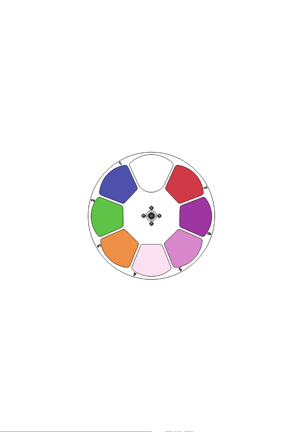
Figure 1: Color wheel
Prism
The MAC Viper Performance is supplied with an interchangeable four-facet 15° rotating prism (P/N
41300070) installed.
Color wheel
The MAC Viper Performance color wheel has 7 interchangeable dichroic filters and an open position
(illustration shows color wheel viewed from lamp side):
As standard, the MAC Viper Performance is supplied with the following color filters installed:
• Slot 1 - Blue 101 - P/N 46404500
• Slot 2 - Green 203 SP - P/N 46404510
• Slot 3 - Orange 311 SP - P/N 46404520
• Slot 4 - 1/2 Minus green SP - P/N 46404541
• Slot 5 - Magenta 522 SP - P/N 46404570
• Slot 6 - Deep Blue SP - P/N 46404550
• Slot 7 - Red 310 SP - P/N 46404560
• Slot 8 - Open
Optical configuration 7
Page 8
Rotating gobos
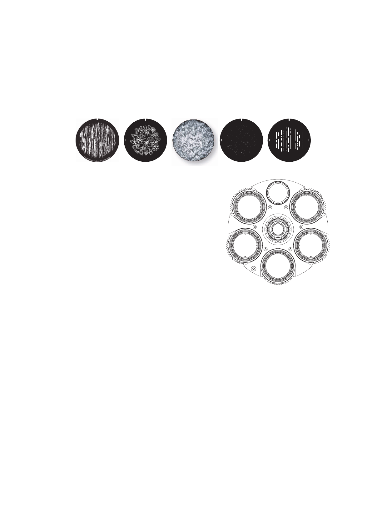
Figure 2: Rotating gobos installed as standard
Slot - Gobo Part number
1. Ray Brush................................................ P/N 43092020
2. Ray Flowers............................................. P/N 43092029
3. Limbo/Crystal in holder............................ P/N 62325152
4. To Boldly Go ............................................ P/N 43092022
5. Light Lines ............................................... P/N 43092023
1
2
3
4
5
Gobo wheel seen from lamp side
4
3
0
9
2
0
2
9
-
B
G
o
b
o
,
R
a
y
F
l
o
w
e
r
s
,
D
3
7
.
5
/
d
2
7
,
h
m
g
l
a
s
s
12345
The gobo wheel in the MAC Viper Performance provides five rotating gobos plus an open position. The
standard gobos are shown in the correct order in Figure 2.
All gobos are interchangeable, but replacement gobos must match the dimensions, construction and quality
of the gobos supplied as standard. The gobos are E-27 size (standard E-size 37.5 mm external diameter,
27 mm image area diameter). Limbo/Crystal is a custom gobo glued permanently into its holder. If you
replace Limbo/Crystal, you will therefore need to order an additional goboholder.
Handling, installing and storing the gobos requires special care. See the MAC Viper Performance Safety
and Installation Guide for details.
4
3
0
9
2
0
2
2
-
A
G
o
b
o
s
s
a
l
g
m
h
,
7
2
d
/
5
.
,
7
T
3
o
D
,
B
o
o
l
G
d
l
y
4
3
0
9
2
0
2
3
-
A
G
o
b
s
s
a
l
g
m
h
,
7
2
d
/
5
o
.
,
7
L
3
i
D
g
,
h
s
t
e
L
n
i
8 MAC Viper Performance User Guide
Page 9
Animation wheel
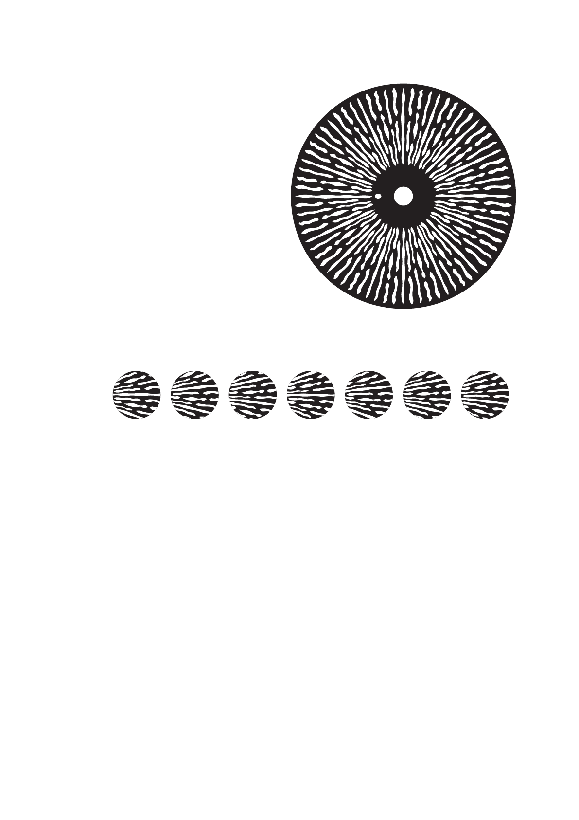
Figure 3: ‘Ripple Waves’ animation wheel
1234567
Figure 4: ‘Ripple Waves’ positions
The MAC Viper Performance is supplied
with the “Ripple Waves” gobo animation
wheel (P/N 43950063) installed. This
wheel provides animation effects when
used in conjunction with gobos.
The wheel can be inserted into the beam,
indexed at any position or at one of seven
predefined positions, and rotated with
variable speed and direction.
4
3
9
5
0
0
6
3
-
B
Optical configuration 9
Page 10
Control panel operations
C
B
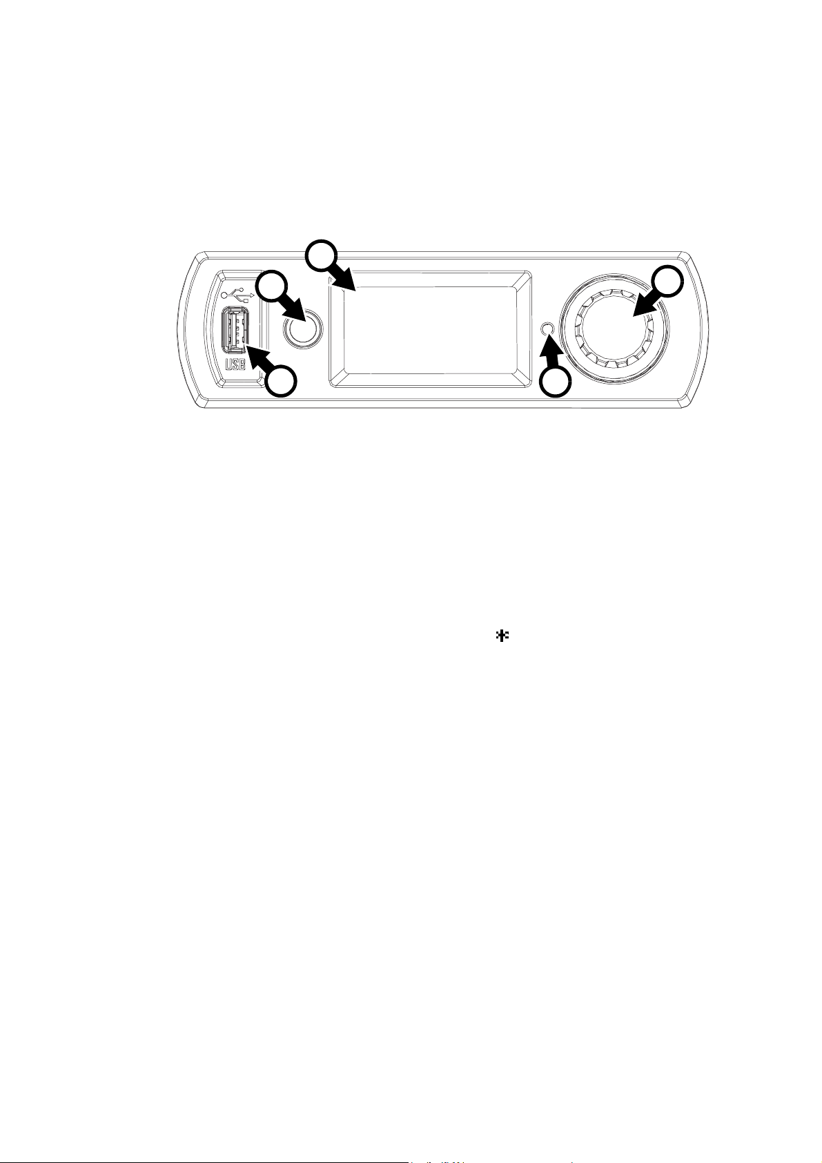
Figure 5: Display and control panel
A
1
DMX ADDRESS
DMX RANGE 1–34
D
E
You can configure individual fixture settings (such as the MAC Viper Performance’s DMX address), read out
data, execute service operations and view error messages using the fixture’s backlit graphic display and
control panel.
When the MAC Viper Performance is powered on, it first boots and resets, then it displays its DMX address
(or its fixture ID number, if one has been set) and any status messages (see page 30) in the display A.
The display can be set to automatically rotate to match standing or hanging fixture orientation in the
PERSONALITY → DISPLAY menu or the Shortcuts menu (see “Shortcuts” on page 11).
Using the control panel
• Click (i.e. press in towards the fixture base once) the jog wheel B to access the menus.
• Rotate the jog wheel to scroll up and down menus.
• Click the jog wheel to enter a menu or make a selection.
• The currently selected item in a menu is indicated by a star .
• Press the Escape button C to step backwards through the menus.
Status LED
An LED D next to the jog wheel indicates fixture status depending on the color displayed and DMX status
depending on whether the LED flashes or lights constantly:
• GREEN: All parameters normal.
• AMBER: Warning (service interval exceeded, for example).
If ERROR MODE is set to Normal, the warning message will be shown in the display. If ERROR MODE is
set to Silent, the display must be activated with the jog wheel to display the warning message.
• RED: Error detected.
If ERROR MODE is set to Normal, the error message will be shown in the display. If ERROR MODE is set
to Silent, the display must be activated with the jog wheel to display the error message.
• FLASHING: No DMX signal detected.
• CONSTANT: Valid DMX signal detected.
Battery power
The display and control panel are powered by the MAC Viper Performance’s onboard battery. This gives
access to the most important functions in the control panel – including DMX addressing – when the fixture is
not connected to AC power.
To activate the display when the fixture is not connected to power, press the Escape button. The display
extinguishes after 10 seconds with no jog wheel activity and the control panel is de-activated after 1 minute
with no jog wheel activity. Press the Escape button again to re-activate.
10 MAC Viper Performance User Guide
Page 11

Shortcuts
If you hold the Escape button pressed in for 2 - 3 seconds, a shortcut menu with the most important
commands appears. Select a command with the jog wheel and click the jog wheel to activate, or press
Escape to cancel.
• RESET ALL resets the whole fixture
• LAMP ON/OFF strikes or douses the lamp.
• ROTATE DISPLAY rotates the MAC Viper Performance display 180°.
Settings stored permanently
The following settings are stored permanently in the fixture memory and are not affected by powering the
MAC Viper Performance off and on or by updating the fixture software:
• DMX address
• DMX Protocol setting
• Fixture ID
• All personality settings (pan/tilt and pan/tilt limit, linked zoom/focus, lamp cooling, fan clean mode,
dimming curve, DMX lamp off, DMX reset, parameter shortcuts, all display settings, error mode)
• Factory settings
• Fixture info (resettable power-on, lamp-on and lamp strike counters)
• All Service settings (adjust, calibration, firmware)
These settings can be returned to factory defaults using the control menus or via DMX.
Service mode
Holding the jog wheel and Escape button pressed in while powering the fixture on puts the fixture into
service mode, in which pan and tilt are disabled and a SERV warning appears in the display. Service mode
removes the risk of unexpected head movement during lamp adjustment. Cycling power and allowing the
fixture to start normally takes it out of service mode.
DMX address
The DMX address, also known as the start channel, is the first channel used to receive instructions from the
controller. For independent control, each fixture must be assigned its own control channels. If you give two
MAC Viper Performances the same address, they will behave identically. Address sharing can be useful for
diagnostic purposes and symmetrical control, particularly when combined with the inverse pan and tilt
options.
DMX addressing is limited, depending which DMX mode the fixture is in, to make it impossible to set the
DMX address so high that you are left without enough control channels for the fixture.
DMX address setting
To set the fixture’s DMX address:
1. Click the jog wheel to enter the main menu.
2. Click the jog wheel to enter DMX ADDRESS, then rotate the jog wheel to scroll to the desired address
and click the jog wheel to save.
3. Press the Escape button to step back to the main menu.
DMX modes
The CONTROL MODE menu lets you set the MAC Viper Performance to one of the two DMX operating
modes, basic 16-bit and extended 16-bit:
• Basic 16-bit mode offers coarse control of all effects plus fine control of gobo indexing angle, pan and tilt.
• Extended 16-bit mode provides all the features of basic 16-bit mode plus fine control of the dimmer, zoom
and focus.
The MAC Viper Performance uses 32 DMX channels in basic 16-bit mode and 35 DMX channels in
extended 16-bit mode. Five more channels in extended 16-bit mode are reserved ready for future control
options.
Control panel operations 11
Page 12

To set the fixture’s DMX mode:
Output
DMX % DMX % DMX % DMX %
Output
Output
Output
Linear S-curve Square law Inverse square law
Figure 6: Dimming curve options
1. Click the jog wheel to enter the main menu.
2. Rotate the jog wheel to scroll down to CONTROL MODE, then click the jog wheel. Rotate the jog wheel
to select either BASIC or EXTENDED, then click the jog wheel to save.
3. Press the Escape button to step back to the main menu.
Fixture ID
The MAC Viper Performance lets you set a four-digit ID number to ease identification of the fixtures in an
installation. When a fixture is powered on for the first time, it displays its DMX address by default. As soon
as you set an ID number other than 0 in FIXTURE ID, the MAC Viper Performance will display this ID
number by default, and indicate FIXTURE ID in the display.
Personality
The MAC Viper Performance provides several options that let you optimize the fixture for different
applications in the PERSONALITY menu:
• The PAN/TILT menu lets you swap and/or invert pan and tilt.
• The SPEED menu lets you set PAN/TILT to NORMAL, FAST (optimized for speed) or SLOW (optimized
for smooth movement – useful for slow movements in long-throw applications). Likewise, you can select
an overall speed for all the effects by setting EFFECT speed to NORMAL, FAST or SLOW. You can also
set effect speed to FOLLOW P/T, in which effects will always use whatever speed is set for pan and tilt.
• DIMMER CURVE provides four dimming options (see Figure 6):
- LINEAR – (optically linear) the increase in light intensity appears to be linear as DMX value is
increased.
- S-CURVE – light intensity control is finer at low levels and high levels and coarser at medium levels.
This curve emulates the RMS voltage dimming characteristics of an incandescent lamp such as the
tungsten halogen lamp of the Martin™ MAC TW1™.
- SQUARE LAW – light intensity control is finer at low levels and coarser at high levels.
- INV SQUARE LAW – light intensity control is coarser at low levels and finer at high levels.
• FOCUS TRACKING sets focus to automatically switch between the three zoom/focus settings when you
use the zoom effect (see “Zoom/focus linking” on page 6).
• GOBO 3 FX RANGE sets the range of positions available on the FX wheel. It is intended to let you restrict
the FX wheel so that only the gobo range or only the gobo animation range is active.
• AUTO LA MP ON gives three lamp strike options:
- When set to OFF, the lamp remains off until a “lamp on” command is received via DMX.
- When set to ON, the lamp strikes automatically after the fixture is powered on.
- When set to DMX, the lamp strikes automatically when the fixture begins to receive DMX data, and
lamp power is shut down 15 minutes after the fixture stops receiving DMX data. Automatic lamp strikes
are staggered to prevent all lamps from striking at once. The delay is determined by the fixture address.
No matter what the AUTOMATIC LAMP ON setting is, the lamp can be struck by sending a Lamp on
command via DMX on the Fixture control/settings channel.
• DMX LAMP OFF and DMX RESET define whether the lamp can be powered off, or whether fixture or
12 MAC Viper Performance User Guide
individual effects can be reset by sending a DMX command on the Fixture control/settings channel. If
either of these settings are set to Off, you can override this setting and cut lamp power or reset effects by
applying a special combination of DMX values (see “DMX protocol” on page 21).
Page 13

• EFFECT SHORTCUT determines whether the gobo wheel and color wheel take the shortest path
between two positions (shortcuts enabled), crossing the open position if necessary, or always avoid the
open position (shortcuts disabled).
• AUTO BLACKOUT lets you set two effects to deploy 5 seconds after a shutter/dimmer blackout to
eliminate any stray light. When enabled, the iris closes and the rotating gobo
• wheel moves to the nearest available position between two slots. This ensures a highly effective blackout,
but snapping open from blackout is not quite as fast because of the time it takes the effects to move away
from their auto blackout positions.
• DISPLAY offers the following options for the LCD display:
- DISPLAY SLEEP determines whether the display remains on permanently, or goes into sleep mode 2,
5 or 10 minutes after the last movement of the jog wheel or Escape button.
- DISPLAY INTENSITY lets you define the brightness of the display backlighting. Select Auto for
automatic adjustment to match the ambient light level, or manually set the intensity to a level from 0% to
100%.
- DISPLAY ROTATION lets you rotate the display through 180° so that it can be read easily if the fixture
is installed with the head hanging below the base.
- DISPLAY CONTRAST lets you define the contrast of the backlit graphic display. Select Auto for
automatic adjustment to match display intensity, or manually set the contrast to a level from 0% to
100%.
• ERROR MODE enables or disables error warnings. If set to NORMAL, the display is activated and lights
up if the fixture needs to report an error. If set to SILENT, the fixture does not light the display with error
warnings but error messages can still be read when the display is activated manually. In both NORMAL
and SILENT modes, the status LED lights amber to indicate a warning and red to indicate an error.
Factory defaults
FACTORY DEFAULT lets you reload the fixture’s factory default settings. Effect calibration is not affected, so
any effects that have been re-calibrated will not be returned to factory calibration settings.
Fixture information readouts
The following fixture information can be called up in the display:
• POWER ON TIME provides two counters:
- The TOTAL counter is not user-resettable and displays total hours powered on since manufacture.
- The RESETTABLE counter is user-resettable and displays the number of hours the fixture has been
powered on since the counter was last reset.
• LAMP ON TIME provides two counters:
- The TOTAL counter is not user-resettable and displays total hours the lamp has been powered on since
manufacture.
- The RESETTABLE counter is user-resettable and displays the number of hours the lamp has been
powered on since the counter was last reset. This counter is intended to allow you to monitor lamp life.
• LAMP STRIKES provides two counters:
- The TOTAL counter is not user-resettable and displays the total number of lamp strikes since
manufacture.
- The RESETTABLE counter is user-resettable and displays the number of lamp strikes since the
counter was last reset.
• SW VERSION displays the currently installed firmware (fixture software) version.
• SERIAL NUMBER displays the fixture’s manufacturer serial number.
• RDM UID displays the fixture’s factory-set unique ID for identification in RDM systems.
• FAN SPEEDS provides separate status readouts from the fixture’s cooling fans.
• TEMPERATURES provides separate PCB temperature readouts.
DMX signal monitoring
The MAC Viper Performance provides data on the DMX signal it is receiving in the DMX LIVE menu. This
information can be useful for troubleshooting control problems.
Control panel operations 13
Page 14

RATE displays the DMX refresh rate in packets per second. Values lower than 10 or higher than 44 may
result in erratic performance, especially when using tracking control.
QUALITY displays the quality of the received DMX data as a percentage of packets received. Values much
below 100 indicate interference, poor connections, or other problems with the serial data link that are the
most common cause of control problems.
START CODE displays the DMX start code. Packets with a start code other than 0 may cause irregular
performance.
The remaining options under DMX LIVE display the DMX values in a range from 0 - 255 that are being
received on each channel. The DMX channels displayed depend on whether the fixture is in 16-bit or 16-bit
extended mode.
Test sequences
TEST activates effects in sequence, allowing you to test all effects, pan and tilt movement only, or effects
only (i.e. without pan and tilt movement) without a DMX controller:
• Select a test type and click on the jog wheel to start the test.
• Click on the Escape button to stop the test.
Manual control
The MANUAL CONTROL menu lets you reset the MAC Viper Performance, strike or douse the lamp, and
operate the fixture without a DMX controller. To execute commands in the MANUAL CONTROL menu,
select a menu item for the effect that you want to control, then enter a value from 0 to 255 to apply a
command. The menu items and values correspond to the commands listed in the DMX protocol on page 21.
14 MAC Viper Performance User Guide
Page 15

Adjusting settings via DMX
Certain fixture settings and parameters can be adjusted from the DMX controller on the Fixture
control/settings channel.
Commands sent on the fixture control channel override any settings entered in the fixture’s onboard control
menus.
To help you avoid accidentally applying a setting that may disrupt a light show, for example, most of the
commands must be held for a certain time before they are applied. For example, the command that turns off
the display illumination must be held for one second to activate it. The command that resets the fixture must
be held for five seconds to activate it. The times required to apply DMX commands on the Fixture
control/settings channel are listed for each command on page 24 in the DMX protocol.
Resetting
Either the entire fixture or individual effects can be reset to their initial positions. Resetting individual effects
can allow on-the-fly recovery if an effect loses its correct position, for example, without having to reset the
entire fixture.
Lamp on / off
The lamp can be struck and doused from the DMX controller.
A peak of electric current that is many times the operating current is drawn for a fraction of a second when
striking a discharge lamp. Striking many lamps at once may cause a voltage drop large enough to prevent
lamps from striking or draw enough current to trip electronic circuit breakers. If sending lamp-on commands
to multiple fixtures, program a sequence that strikes lamps one at a time.
Illuminating the display
The fixture’s display panel can be brought out of sleep mode with a DMX command. This makes it possible
to read the fixture’s DMX address while the fixture is installed in the rig.
After being illuminated in this way, the display will return to sleep mode according to the setting entered in
the onboard control menus.
Control menu setting overrides
The following fixture settings can be adjusted via DMX, overriding the settings entered in the onboard
control menus. See under “Control panel menus” on page 26 for details of these settings.
• Dimming curve
• Pan and tilt speed
• Effect shortcuts
• Zoom/focus linking
• Ballast output
• Beam smoothing
• Auto blackout
• Calibration offsets
Adjusting settings via DMX 15
Page 16

Changing calibration offsets using DMX
255
192
128
64
0
+5%
+2.5%
0
-2.5%
-5%
Effect channel
DMX value
Offset
value
Figure 7: Offset values
The Fixture control/settings DMX channel allows effects to
be calibrated by changing their factory default offsets from
the DMX controller.
To set an effect offset:
1. Set the effect to a DMX value from 0 to 255 on its own
DMX channel (for example, set Cyan to 192 on channel
4).
2. Send a ‘Store’ command for the effect on the Fixture
control/settings channel.
The MAC Viper Performance now reads the value on the
effect channel (192 for Cyan in the example above),
translates it to an offset value of between -5% and +5% as
shown in Figure 7 (+2.5% Cyan offset in the example
above) and stores that offset in memory.
See the Fixture control/settings channel on page 24 in the
DMX protocol for details of the effect offsets that can be
set using this method.
Effect offsets stored in memory are not affected by
powering the fixture off and on or by updating the fixture
software. To return all offsets to their factory defaults, send
a DMX value from 245 to 249 for 5 seconds on the Fixture
control/settings channel or apply LOAD FACTORY
SETTINGS in the FACTORY SETTINGS menu in the
fixture’s control panel.
16 MAC Viper Performance User Guide
Page 17

RDM
The MAC Viper Performance can communicate using RDM (Remote Device Management) in accordance
with ESTA’s American National Standard E1.20-2006: Entertainment Technology RDM Remote Device
Management Over DMX512 Networks.
RDM is a bi-directional communications protocol for use in DMX512 control systems, it is the open standard
for DMX512 device configuration and status monitoring.
The RDM protocol allows data packets to be inserted into a DMX512 data stream without affecting existing
non-RDM equipment. It allows a console or dedicated RDM controller to send commands to and receive
messages from specific fixtures.
RDM ID
Each MAC Viper Performance has a factory-set RDM UID (unique identification number) that makes it
addressable and identifiable in RDM systems. The number can be found in the control panel
INFORMATION menu under RDM UID.
RDM communication
The MAC Viper Performance supports a range of RDM PIDs (Parameter IDs). Sending
SUPPORTED_PARAMETERS and PARAMETER_DESCRIPTION commands from an RDM controller will
call up a list of the PIDs supported in the firmware version installed in the fixture.
RDM 17
Page 18

Software service functions
Service utilities
The control panel SERVICE menu provides utilities for technicians rigging or servicing the fixture:
• ERROR LIST displays any error messages that are stored in internal memory.
• PT FEEDBACK lets you disable feedback to the fixture software from the pan, tilt and effects positioning
systems. If feedback is set to ON and a pan, tilt or effect position error is detected, the shutter closes and
the effect resets. This feature can be disabled by setting feedback to OFF.
The OFF setting is not saved when the fixture is powered off, and the system will be re-enabled the next
time the fixture starts. If a pan/tilt position error occurs and the system cannot correct pan/tilt position
within 10 seconds, feedback is automatically disabled.
• ADJUST is for use at the factory and by authorized Martin Service technicians only and is intended for
use after replacement of components, etc. If you want to adjust the default positions of the MAC Viper
Performance effects, use the CALIBRATION menu.
Important! Do not enter the ADJUST menu without service documentation from Martin™.
• CALIBRATION lets you set new default positions for calibration purposes, set effects to their factory
default positions or overwrite the factory default positions with new values. See ”Calibration” below.
• USB lets you updates the firmware (fixture software) using a USB memory device. For a detailed guide to
updating the firmware, see ”Installing using a USB memory device” later in this chapter.
Calibration
The CALIBRATION menu lets you define offsets in software that are relative to the mechanical reset or
home positions. This allows you to fine-tune optical alignment and achieve uniform performance between
fixtures. Fixtures are adjusted and calibrated at the factory, and further calibration will normally only be
necessary if fixtures have been subjected to abnormal shocks during transport or if normal wear and tear
has affected alignment after an extended period of use.
Calibrating pan and tilt sensors
Warning! Be ready for the head to move during pan and tilt calibration.
To calibrate pan and tilt:
1. Place the fixture on a stable surface.
2. In the CALIBRATION menu, select PT AT END STOP.
3. Move pan to its end stop position by rotating the yoke clockwise (as seen from above the head looking
towards the base) to maximum pan.
4. Move tilt to its end stop by tilting the head to its maximum angle with the front glass pointing towards the
base and away from the display/control panel.
5. Be ready for the head to move. Click the jog wheel to register the positions. The fixture will display
Saving... and the head will move.
6. Press the Escape button to exit pan/tilt sensor calibration. Be ready for the head to move again.
Calibrating effects
Calibration can be carried out via DMX (see ”Changing calibration offsets using DMX” on page 16) but the
most thorough approach is probably to set multiple fixtures to the same position (e.g. dimmer open 1%) and
then calibrate each fixture using its onboard control panel while comparing its light output with a reference
fixture.The calibration range available for each effect varies but is approximately 5%. After selecting a
calibration value, click on the jog wheel to set the effect to that value.
18 MAC Viper Performance User Guide
Page 19

Loading and storing default calibration offsets
In the CALIBRATION menu, LOAD DEFAULTS lets you load the factory default calibration offsets stored in
memory.
SAVE DEFAULTS lets you overwrite the factory default calibration offsets stored in memory with any new
offsets that you have defined. Overwriting is permanent, so once you have saved new default offsets, LOAD
DEFAULTS will reload the new offsets.
Firmware installation
The currently installed firmware (fixture software) version can be viewed in the control panel INFORMATION
menu. Firmware updates are available from the Martin™ website and can be installed using a USB memory
stick or a Windows PC running the Martin Uploader application and either a Martin Universal USB Duo™
USB-DMX interface device or a Martin DABS1™ USB-DMX interface device.
Calibration data is stored in the relevant modules wherever possible so that a module will stay calibrated if is
removed from the fixture or installed in another fixture.
Do not switch the fixture off during a firmware update, or firmware will be corrupted.
Installing using a USB memory device
The following are required in order to install firmware using a USB memory device:
• The MAC Viper Performance ‘.BANK’ firmware update file, available for download from the Martin website
at http://www.martin.com.
• A USB memory stick with the update file copied from a PC into the USB stick’s root directory.
To install the MAC Viper Performance firmware:
1. Download the ‘.BANK’ firmware file from the MAC Viper Performance Product Support page at
www.martin.com, read the firmware release notes carefully to check for any instructions or warnings,
and copy the firmware file to the root directory of a USB stick.
2. Disconnect the data link from the MAC Viper Performance.
3. Insert the USB stick in the MAC Viper Performance’s USB host socket. The fixture should recognize the
USB stick, illuminate the display and show UPDATING FILES in the display while it checks and if
necessary updates its internal memory with new firmware versions stored on the USB stick. If the fixture
does not recognize the USB stick, scroll to the USB menu under SERVICE in the control panel.
Important! Do not remove a USB memory device while the fixture is updating files.
4. When the fixture has updated its internal memory, AVAILABLE FIRMWARE will appear in the display.
You can now scroll through the firmware versions available in memory.
5. To install a firmware version, select it by scrolling and then clicking with the jog wheel. The MAC Viper
Performance asks you to confirm installation of the new firmware. If you do not want to install that
version, press the Escape button.
6. Allow the fixture to install the firmware and reboot.
7. Remove the USB stick. The newly-installed firmware version will now be displayed in the
INFORMATION menu.
8. Reconnect the data link.
9. If you have installed a new firmware version, check the Martin™ website to see whether an updated
User Guide is available for this firmware.
Fixture information and settings, including zoom-focus linking, are not affected when new software is
uploaded.
Installing using a PC and hardware interface
The following are required in order to install firmware using a PC:
• The MAC Viper Performance firmware ‘.MU3’ update file, available for download from the Product Support
area of the Martin website at http://www.martin.com.
• A Windows PC running the latest version of the Martin Uploader™ application (also available for
download free of charge from www.martin.com) and loaded with the firmware update file.
• A USB-DMX hardware interface device such as the Martin USB Duo™ or Martin DABS1™.
To install the MAC Viper Performance firmware:
Software service functions 19
Page 20

1. Download the firmware ‘.MU3’ file from the MAC Viper Performance support page on the Martin website
to the PC.
2. Read the firmware release notes carefully to check for any instructions or warnings.
3. Follow the instructions for an auto upload/upload via DMX in the Martin Uploader application help files
and supplied with the hardware interface.
20 MAC Viper Performance User Guide
Page 21

DMX protocol
Applicable when running MAC Viper Performance firmware version: 1.0.0
Basic
16-bit
Mode
16-bit
Extended
Mode DMX Value Percent Function
11
2
2
3
34
45
56
67
78
0 - 19
20 - 49
50 - 200
201 - 210
211 - 255
0 - 65535 0 - 100
0 - 255 0 - 100
0 - 255 0 - 100
0 - 255 0 - 100
0 - 255 0 - 100
0
1 - 14
15
16 - 29
30
31 - 44
45
46 - 59
60
61 - 74
75
76 - 89
90
91 - 104
105
106 - 119
120 - 160
161 - 163
164 - 166
167 - 169
170 - 172
173 - 175
176 - 178
179 - 181
182 - 192
193 - 214
215 - 221
222 - 243
244 - 247
248 - 251
252 - 255
0 - 7
8 - 19
20 - 78
79 - 82
82 - 100
0
1 - 5
6
6 - 11
12
12 - 17
18
18 - 23
23
24 - 29
29
30 - 35
35
36 - 41
41
41 - 46
47 - 63
63 - 64
64 - 65
65 - 66
66 - 67
68
69 - 70
70 - 71
71 - 75
75 - 84
84 - 86
87 - 95
95 - 96
97 - 98
98 - 100
Fade
Default
type
value
Strobe/shutter
Shutter closed (Lamp switches to 800 watt mode after shutter is closed
for 10 seconds)
Shutter open
Strobe, slow → fast
Shutter open
Random strobe, slow → fast
Dimmer fade (MSB)
Closed → open
Dimmer fade, fine (LSB) Fade 0
Cyan
White → full cyan
Magenta
White → full magenta
Yellow
White → full yellow
CTO
Open (6000 K) → warm (3200 K)
Color Wheel
Continuous Scroll
Open
Open → Slot 1
Slot 1
Slot 1 → Slot 2
Slot 2
Slot 2 → Slot 3
Slot 3
Slot 3 → Slot 4
Slot 4
Slot 4 → Slot 5
Slot 5
Slot 5 → Slot 6
Slot 6
Slot 6 → Slot 7
Slot 7
Slot 7 → Open
Open
Stepped Scroll (snap to full color positions)
Slot 1
Slot 2
Slot 3
Slot 4
Slot 5
Slot 6
Slot 7
Open
Continuous Rotation
CW, Fast → Slow
Stop (This will stop the color wheel wherever it is at the time)
CCW, Slow → Fast
Random color
Fast
Medium
Slow
Snap 30
Fade 0
Fade 0
Fade 0
Fade 0
Fade 0
Snap 0
Table 1: DMX Protocol
DMX protocol 21
Page 22

Basic
16-bit
Mode
16-bit
Extended
Mode DMX Value Percent Function
89
910
10 11
11 1 2
12 13
0 - 9
10 - 14
15 - 19
20 - 24
25 - 29
30 - 34
35 - 39
40 - 44
45 - 49
50 - 54
55 - 59
60 - 89
90 - 119
120 - 149
150 - 179
180 - 209
210 - 232
233 - 255
0 - 65535
0 - 600
601 - 32130
32131 - 32895
32896 - 64515
64516 - 65535
0 - 10
11 - 20
21 - 30
31 - 40
41 - 50
51 - 60
61 - 70
71 - 80
81 - 90
91 - 100
101 - 110
111 - 255
0 - 255
0 - 2
3 - 126
127 - 129
130 - 253
254 - 255
0 - 4
4 - 5
5 - 8
8 - 10
10 - 12
12 - 13
14 - 16
16 - 17
18 - 19
20 - 21
21 - 23
23 - 35
35 - 46
47 - 58
59 - 70
70 - 82
82 - 91
91 - 100
0 - 100
0
1 - 49
49 - 50
50 - 99
100
0 - 4
4 - 8
8 - 12
12 - 16
16 - 20
20 - 23
24 - 27
28 - 31
32 - 35
36 - 39
39 - 43
43 - 100
0 - 100
0 - 1
1 - 49
50
51 - 99
99 - 100
Gobo selection, indexing, shake, rotation
Indexed gobo: set indexed angle on channels 9/10 (16-bit) or 10/11
(16-bit ext.)
Open
Gobo 1
Gobo 2
Gobo 3
Gobo 4
Gobo 5
Continuous gobo rotation: set gobo rotation speed on channels 9/10
(16-bit) or 10/11 (16-bit ext.)
Gobo 1
Gobo 2
Gobo 3
Gobo 4
Gobo 5
Gobo shake centered on indexed position: set indexed angle on
channels 9/10 (16-bit) or 10/11 (16-bit ext.). Shake angle increments in
following steps: 10°, 15°, 30°, 45°, 60°, 90°, 135°, 180°, 270° and 360°
Gobo 1, 360° slow → 10° fast
Gobo 2, 360° slow → 10° fast
Gobo 3, 360° slow → 10° fast
Gobo 4, 360° slow → 10° fast
Gobo 5, 360° slow → 10° fast
Continuous gobo wheel scroll with continuous gobo rotation: set gobo
rotation speed on channels 9/10 (16-bit) or 10/11 (16-bit extended)
CW gobo wheel scroll, fast → slow
CCW gobo wheel scroll, slow* → fast
Gobo indexing angle, rotation speed (16-bit fine, MSB and LSB)
If indexed gobo is selected on channel 8 (16-bit) or 9 (16-bit ext.)
Gobo indexing, -197.5° → +197.5°
(default DMX value 32768 sets gobo to 0°)
If continuous gobo rotation is selected on channel 8 (16-bit) or 9 (16-bit
ext.)
No gobo rotation, gobo indexed at 0°
CW, fast → slow
No gobo rotation, gobo stops at current position
CCW, slow → fast
No gobo rotation, gobo indexed at 90°
Animation wheel rotation
Open
Indexed (set indexing angle on channel 12/13)
Open
Continuous rotation
(set rotation speed and directions on channel 12/13)
Position 1
Position 2
Position 3
Position 4
Position 5
Position 6
Position 7
Open
Animation wheel indexed angle, rotation speed and direction
If indexing is selected on channel 11/12
Indexed angle
If continuous rotation is selected on channel 11/12
Stop, indexed at 0°
CW rotation, fast → slow
Stop, wheel stops at its current position
CCW rotation, fast → slow
Stop, indexed at 90°
Fade
Default
type
value
Snap 0
Fade 32768
Snap 0
Snap 127
Table 1: DMX Protocol
22 MAC Viper Performance User Guide
Page 23

Basic
16-bit
Mode
Extended
13 14
14 15
15 16
16 17
17 18
18 19
19 20
20 21
21 22
22 23
23 24
24 25
25 26
26
27
28 31
29 32
30 33
31 34
16-bit
Mode DMX Value Percent Function
Framing blade 1, position
Out → in
Framing blade 1, angle
Angle –
Para ll el
50
Angle +
Framing blade 2, position
Out → in
Framing blade 2, angle
Angle –
Para ll el
50
Angle +
Framing blade 3, position
Out → in
Framing blade 3, angle
Angle –
50
Para ll el
Angle +
Framing blade 4, position
Out → in
Framing blade 4, angle
Angle –
50
Para ll el
Angle +
Frame indexing angle
Minimum (-55°)
50
0°
Maximum (+55°)
Frost
No frost → Full frost
Prism
Prism off
Prism indexing: set angle on ch. 24 (16-bit) or 25 (16-bit ext.)
Prism rotation: set direction and speed on ch. 24 (16-bit) or 25 (16-bit
ext.)
Prism indexing angle, rotation speed and direction
If prism indexing is selected on channel 23 (16-bit) or 24 (16-bit ext.):
Angle –
0°
50
Angle +
If prism rotation is selected on channel 23 (16-bit) or 24 (16-bit ext.):
Prism stop, indexed at 0°
0
CW rotation, fast → slow
Prism stop at its current position
51
CCW rotation, slow → fast
Prism stop, indexed at 45°
100
Iris
Open → closed
Zoom, 16-bit (MSB and LSB)
Flood → spot
Focus, 16-bit (MSB and LSB)
Infinity → near
Pan, 16-bit (MSB and LSB)
Left → right (32768 = neutral)
Tilt, 16-bit (MSB and LSB)
Up → down (32768 = neutral)
27
28
29
30
0 - 255 0 - 100
0 -126
127 - 128
129 - 255
0 - 255 0 - 100
0 -126
127 - 128
129 - 255
0 - 255 0 - 100
0 -126
127 - 128
129 - 255
0 - 255 0 - 100
0 -126
127 - 128
129 - 255
0 -126
127 - 128
129 - 255
0 - 255 0 - 100
0 -10
11 - 138
139 - 255
0 -126
128
129 - 255
0 - 2
3 - 126
127 - 129
130 - 253
254 - 255
0 - 255 0 - 100
0 - 65535 0 - 100
0 - 65535 0 - 100
0 - 65535 0 - 100
0 - 65535 0 - 100
0 - 49
51 - 100
0 - 49
51 - 100
0 - 49
51 - 100
0 - 49
51 - 100
0 - 49
51 - 100
0 - 4
4 - 54
54 - 100
0 - 49
51 - 100
1 - 50
52 - 99
Fade
Default
type
value
Fade 0
Fade 127
Snap 0
Fade 127
Fade 0
Fade 127
Fade 0
Fade 127
Fade 127
Fade 0
Snap 0
Fade 128
Fade 0
Fade 32768
Fade 32768
Fade 32768
Fade 32768
Table 1: DMX Protocol
DMX protocol 23
Page 24

Basic
16-bit
Mode
16-bit
Extended
Mode DMX Value Percent Function
32 35
-36
-37
0 - 9
10 - 14
15 - 19
20 - 24
25 - 29
30 - 34
35 - 39
40 - 44
45 - 49
50 - 54
55 - 59
60 - 64
65 - 69
70 - 74
75 - 79
80 - 84
85 - 89
90 - 94
95 - 99
100 - 104
105 - 109
110 - 114
115 - 119
120 - 124
125 - 126
127 - 128
129 - 130
131 - 132
133 - 134
135 - 144
145 - 149
150 - 154
155 - 159
160 - 164
165 - 169
170 - 174
175 - 179
180 - 184
185 - 189
190 - 194
195 - 199
200 - 204
205 - 214
215 - 219
220 - 224
225 - 229
230 - 234
235 - 239
240 - 244
245 - 249
250 - 255
0 - 4
4 - 5
6 - 7
8 - 9
10 - 11
12 - 13
14 - 15
16 - 17
18 - 19
20 - 21
21 - 23
23 - 25
25 - 27
28 - 29
29 - 31
32 - 33
34 - 35
35 - 37
37 - 39
39 - 41
41 - 43
43 - 45
45 - 46
47 - 48
49
50
50 - 51
51 - 52
52
53 - 56
57 - 58
59 - 60
61 - 62
62 - 63
64 - 66
66 - 68
68 - 70
70 - 72
72 - 74
74 - 76
76 - 78
78 - 80
80 - 84
84 - 86
86 - 88
88 - 89
90 - 91
92 - 93
94 - 95
96 - 97
98 - 100
Fixture control/settings
(hold for number of seconds indicated to activate)
No function (disables calibration) – 5 sec.
Reset entire fixture – 5 sec.
Reset dimmer and shutter only – 5 sec.
Reset CMY, CTO and color wheel only – 5 sec.
Reset effects (gobo and animation wheels, iris, prism, frost, zoom,
focus) only – 5 sec.
Reset pan and tilt only – 5 sec.
Reset framing – 5 sec.
Lamp on
Lamp off – 5 sec.
No function
Enable calibration – 5 sec.
Linear dimming curve – 1 sec.
(menu override, setting unaffected by power off/on)
Square law dimming curve – 1 sec.
(menu override, factory default setting, setting unaffected by power
off/on)
Inverse square law dimming curve – 1 sec.
(menu override, setting unaffected by power off/on)
S-curve dimming curve– 1 sec.
(menu override, setting unaffected by power off/on)
Normal pan and tilt speed – 1 sec.
(menu override - setting returns to MENU setting after power on/off)
Fast pan and tilt speed – 1 sec.
(default setting, menu override - setting returns to MENU setting after
power on/off)
Slow pan and tilt speed – 1 sec.
(menu override - setting returns to MENU setting after power on/off)
Effect shortcuts = ON – 1 sec.
(default setting, menu override, setting stays at factory default ON at
power off/on)
Effect shortcuts = OFF – 1 sec.
(menu override, setting returns to factory default ON at power off/on)
Disable zoom/focus linking– 1 sec.
Enable zoom/focus linking, near distance – 1 sec.
Enable zoom/focus linking, medium distance (default setting) – 1 sec.
Enable zoom/focus linking, far distance – 1 sec.
Ballast output full, set to 100% (default setting)
Ballast output reduced to 90%
Ballast output reduced to 80%
Ballast output reduced to 70%
Ballast output reduced to 60%
No function
Auto blackout = ON – 1 sec.
Auto blackout = OFF – 1 sec. (default setting)
Turn on display – 1 sec.
Turn off display – 1 sec.
Store pan and tilt calibration – 5 sec.
Store dimmer calibration – 5 sec.
Store cyan calibration – 5 sec.
Store magenta calibration – 5 sec.
Store yellow calibration – 5 sec.
Store CTC calibration – 5 sec.
Store all CMY and CTC calibration – 5 sec.
Store gobo wheel current slot index calibration – 5 sec.
No function
Store prism calibration – 5 sec.
Store iris calibration – 5 sec.
Store focus calibration – 5 sec.
Store zoom calibration – 5 sec.
Store pan calibration – 5 sec.
Store tilt calibration – 5 sec.
Reset all calibration values to factory defaults – 5 sec.
No function
Reserved for future use
Reserved for future use
Fade
Default
type
value
Snap 0
Table 1: DMX Protocol
24 MAC Viper Performance User Guide
Page 25

Basic
16-bit
Mode
16-bit
Extended
Mode DMX Value Percent Function
-38
-39
-40
MSB = Most significant byte
LSB = Least significant byte
Reserved for future use
Reserved for future use
Reserved for future use
Table 1: DMX Protocol
Fade
type
Default
value
DMX protocol 25
Page 26

Control panel menus
Applicable when running MAC Viper Performance firmware version 1.0.0.
Menu level 1 Menu level 2 Menu level 3 Menu level 4 Notes (Default settings in bold print)
DMX address (default address = 1). The
DMX ADDRESS 1 – XXX
BASIC
CONTROL MODE
EXTENDED
FIXTURE ID 0 – 9999 User-settable fixture ID number
PAN INVERT ON/OFF Reverse DMX pan control: right → left
TILT INVERT ON/OFF Reverse DMX tilt control: down → up
NORMAL Normal speed pan and tilt
PA N/ T I LT
EFFECT
LINEAR Optically linear dimming curve
SQUARE LAW Square law dimming curve
INV SQ LAW Inverse square law dimming curve
S-CURVE
DISABLED Disables zoom focus linking
NEAR
MEDIUM
FAR
OFF Automatic lamp striking disabled
ON
DMX
ON Lamp can be powered off via DMX
OFF
FAST Optimize pan/tilt movement for speed
SLOW
FOLLOW P/T
NORMAL Normal effects speed
FAST Optimize effects movement for speed
SLOW
PERSONALITY
PA N/ T I LT
SPEED
DIMMER CURVE
FOCUS
TRACKING
AUTO LAMP O N
DMX LAMP OFF
DMX address range is limited so that the
fixture will always have enough DMX
channels within the 512 available.
16-bit basic DMX mode with 2-channel
(coarse and fine) control of gobo indexing
and speed, pan and tilt
16-bit extended DMX mode with basic
mode features plus fine control of dimmer,
zoom and focus. Five channels are also
reserved for future effects.
0
Optimize pan/tilt movement for
smoothness
Effects speed follows the speed setting
applied to pan and tilt via DMX or in
control menu
Optimize effects movement for
smoothness
S-curve (fixture emulates incandescent
lamp voltage linear RMS dimming curve)
Enables zoom focus linking, optimized for
short-throw projection (5 - 10 m)
Enables zoom focus linking, optimized
for medium-throw projection (10 - 20 m)
Enables zoom focus linking, optimized for
long-throw projection (20+ m)
Lamp strikes automatically within 90
seconds of fixture being powered on
Lamp strikes automatically when the
fixture receives a DMX signal
Lamp cannot be powered off via DMX (can
be overridden: see DMX protocol)
Table 2: Control menus
26 MAC Viper Performance User Guide
Page 27

Menu level 1 Menu level 2 Menu level 3 Menu level 4 Notes (Default settings in bold print)
ON Fixture can be reset via DMX
PERSONALITY
(continued)
FAC TOR Y
DEFAULT
INFORMATION
DMX RESET
EFFECT
SHORTCUT
AUTO BL AC KOUT
DISPLAY
ERROR MODE
LOAD FACTORY
SETTINGS
POWER ON TIME
LAMP ON TIME
LAMP STRIKES
SW VERSION* XX.XX.XX Displays currently active software version
SERIAL
NUMBER*
RDM UID* 4D50.XXXXXXXX Displays fixture’s unique RDM ID
FAN SPEEDS*
TEMPERATURES*
OFF
ON
OFF
OFF
ON
ON Display permanently on
2 MINUTES
DISPLAY SLEEP
DISPLAY
INTENSITY
DISPLAY
ROTATION
DISPLAY
CONTRAST
NORMAL
SILENT
ARE YOU SURE?
TOTAL 0 ... XXX HR
RESETTABLE
TOTAL 0 ... XXX HR
RESETTABLE
TOTAL 0 ... XXX HR
RESETTABLE
(XX)XXXXXXXXXXXX Displays fixture’s serial number
LAMPFAN L ...
BASEFAN 4
ZOOM/FOCUS ...
BALLAST
5 MINUTES
10 MINUTES
10 ... 100 Set display intensity in % (default = 100)
NORMAL /
ROTATE 180
1 ...100 Adjust contrast of display (default = 41)
YES/NO
CLEAR
COUNTER?
YES/NO
CLEAR
COUNTER?
YES/NO
CLEAR
COUNTER?
YES/NO
0 - XXX RPM
X C
Fixture cannot be reset via DMX (can be
overridden: see DMX protocol)
Effects take shortest route during
changes, crossing open positions if
necessary
Effects avoid open positions during effects
changes
Shutter/dimmer blackout does not call
up other effects.
Iris and gobo wheel are deployed 5
seconds after shutter/dimmer blackout to
eliminate stray light.
Display goes into sleep mode 2 minutes
after last key press
Display goes into sleep mode 5 minutes
after last key press
Display goes into sleep mode 10 minutes
after last key press
Display orientation normal or rotated 180°
Enable error messages and warnings in
display
Disable error messages and warnings in
display (the status LED will still light to
indicate fixture status if an error has been
detected or the fixture has a warning)
Return all settings (except calibrations) to
factory defaults
Display hours fixture has been powered on
since manufacture (not user-resettable)
Display hours fixture has been powered on
since last counter reset (user-resettable)
Display hours of lamp use since
manufacture
(not user-resettable)
Display hours of lamp use since last
counter reset (user-resettable)
Display number of times lamp has been
struck since manufacture (not
user-resettable)
Display number of times lamp has been
struck since last counter reset
(user-resettable)
Displays current speed of all cooling fans
(lamp, head and base)
Displays temperature in °C of all PCBs and
of ballast capacitor
Table 2: Control menus
Control panel menus 27
Page 28

Menu level 1 Menu level 2 Menu level 3 Menu level 4 Notes (Default settings in bold print)
DMX transmission speed in packets per
second
Value received on each DMX channel
(values for fine control channels can only
be viewed if available in the DMX mode
the fixture is set to)
Run test sequence of all functions. Press
Escape button to stop test
Run test sequence of pan and tilt
functions. Press Escape button to stop test
Run test sequence of all effects. Press
Escape button to stop test
Adjust color temperature control (add
warmth)
Select animation wheel function (indexing
or rotation)
Set animation wheel indexed angle or
rotation speed
Framing system indexing - rotation to
+/- 55° (default = 128)
DMX LIVE*
TEST*
MANUAL
CONTROL*
RATE 0 - 44 HZ
QUALITY 0 - 100% Percent of packets received
START CODE 0 - 255 Value of the DMX start code
STROBE/SHUTTER ...
TEST ALL
TEST PAN/TILT
TEST EFFECTS
RESET RESET Click jog wheel to reset fixture
LAMP ON/OFF Manually strike/douse lamp
STROBE/
SHUTTER
DIMMER 0 - 255 Set dimmer opening
DIMMER FINE 0 - 255 Set dimmer opening, fine (LSB)
CYAN 0 - 255 Add cyan
MAGENTA 0 - 255 Add magenta
YELLOW 0 - 255 Add yellow
CTC 0 - 255
COLOR WHEEL 0 - 255 Select color filter
GOBO W 1 SEL 0 - 255 Select gobo
GOBO W 1 I/R 0 - 255 Adjust gobo indexing/rotation
GOBO W 1 I/R
FINE
ANIMATION FUNC 0 - 255
ANIMATION
WHEEL
FRAMING 1 POS 0 - 255 Framing blade 1 insertion
FRAMING 1
ANGLE
FRAMING 2 POS 0 - 255 Framing blade 2 insertion
FRAMING 2
ANGLE
FRAMING 3 POS 0 - 255 Framing blade 3 insertion
FRAMING 3
ANGLE
FRAMING 4 POS 0 - 255 Framing blade 4 insertion
FRAMING 4
ANGLE
FRAMING
ROTATION
FROST 0 - 255 Frost insertion
PRISM I/R 0 - 255 Set prism indexing/rotation
PRISM INX 0 - 255 Set prism indexed position
IRIS 0 - 255 Set iris aperture
ZOOM 0 - 255 Set zoom (default = 128)
ZOOM FINE 0 - 255 Set zoom, fine (LSB, default = 128)
0 - 255 Set shutter/strobe effect (default = 30)
0 - 255 Adjust gobo indexing/rotation, fine (LSB)
0 - 255
0 - 255 Framing blade 1 angle
0 - 255 Framing blade 2 angle
0 - 255 Framing blade 3 angle
0 - 255 Framing blade 4 angle
0 - 255
Table 2: Control menus
28 MAC Viper Performance User Guide
Page 29

Menu level 1 Menu level 2 Menu level 3 Menu level 4 Notes (Default settings in bold print)
FOCUS 0 - 255 Set focus
FOCUS FINE 0 - 255 Set focus, fine (LSB, default = 128)
MANUAL
CONTROL*
(continued)
SERVICE
PAN 0 - 255 Set pan angle (default = 128)
PAN FINE 0 - 255 Set pan angle, fine (LSB, default = 128)
TILT 0 - 255 Set tilt angle (default = 128)
TILT FINE 0 - 255 Set tilt angle, fine (LSB, default = 128)
ERROR LIST Empty or up to 20 errors Display any errors in memory
FAN CLEAN ON/OFF Activate fan cleaning
Enable pan/tilt position feedback
systems
Important! For use by authorized
service technicians during mechanical
adjustment only. Do not enter the
ADJUST menu without Martin™ service
documentation, or you may make the
fixture impossible to use correctly.
Jog wheel must be held in for 5 seconds to
enter.
Calibrate pan/tilt sensor by turning pan
clockwise against end stop, and tilt against
end stop pointing away from display, then
push ACTION
Set individual effects to calibration
positions (approx. +/- 5% offset available)
Replace factory default calibration settings
with current calibration settings
No USB device present or no firmware on
USB device
Fixture updating internal memory from
USB device
Select firmware from versions stored in
internal memory. Select version, then click
on jog wheel and confirm your choice to
update
PT FEEDBACK
ADJUST
CALIBRATION
FIRMWARE
UPDATE
ON
OFF Disable pan/tilt position feedback
DIMMER
FROST
FRAMING
PT AT END STOP ACTION
DIMMER ... TILT
LOAD DEFAULTS Load factory default calibration settings
SAVE DEFAULTS
NO DEVICE
UPDATING FILES
AVAI LABL E
FIRMWARE
ADJUSTED/
NOT ADJUSTED
NOT ADJUSTED/
1 - 255
ADJUST
RESET/FRAMING
BLADE 1
LEFT...FRAMING
BLADE 4 RIGHT
PERFORMANCE
1.0.0
...
PERFORMANCE
X.X.X
Table 2: Control menus
* Menus marked * are available only when the fixture is connected to mains power. All other menus are available in mains- and
battery-powered operation.
Control panel menus 29
Page 30

Service and display messages
The MAC Viper Performance gives service and maintenance information by displaying a large 3- or
4-character short code and a smaller full-text message in the fixture’s display. The short code is visible at a
distance, allowing easier reading with the fixture still in the rig, for example, while the full-text message gives
more detailed information.
Warning messages
Warning messages indicate that either:
• problems might appear in the future if no action is taken, or
• the user needs to pay special attention to a function or procedure when working with the fixture.
The MAC Viper Performance communicates warnings as follows:
• Warning codes are shown continuously in the display and disappear when the user reacts to the warning.
• If more than one warning is detected, all warnings are displayed in sequence.
• If the display is inactive, the fixture’s status LED (see Figure 5 on page 10) flashes orange to indicate that
there is a warning. Activating the display will show the warning.
The possible warning messages are listed in Table 3 below
:
Short code
BANK
BATW
CMTW
DINA
EFTW
FRNA
FTNA
G1xM
HOT
INLK
LTI M
PTTW
PUTW
Long message and explanation
BANK NO ACCESS
Error unpacking firmware bank during/after software upload. Fixture will continue to operate on
existing firmware. Warning message is cleared by a successful software upload or at the next
power off/on cycle.
BAL TEMP HIGH
Ballast PCB sensor detects that normal operating temperature is exceeded.**
CMY TEMP HIGH
CMY PCB sensor detects that normal operating temperature is exceeded.**
DIMMER ADJUST
No dimmer adjustment data in EEPROM. Dimmer may be incorrectly adjusted*.
EFF TEMP HIGH
Effects PCB sensor detects that normal operating temperature is exceeded.**
FRAMING ADJUST
No framing adjustment data in EEPROM. Framing effect may be incorrectly adjusted*.
FROST ADJUST
No frost adjustment data in EEPROM. Frost effect may be incorrectly adjusted*.
GOBO 1-x MISSING
Gobo x not detected at last reset. If no gobos are detected, an RxER message is also displayed.
LAMP HOT
Lamp is too hot to restrike. Pan and tilt are disabled for 8 minutes to reduce the risk of falling
fragments if the lamp has exploded. Fixture will attempt to restrike at one-minute intervals. If
lamp still refuses to strike after eight attempts, an LAER (Lamp Error) message is displayed.
INVALID LICENSE KEY
Invalid license key entered. Warning is displayed and it is impossible to enter a license key for
10 seconds.
LAMP LIFETIME
Lamp lifetime counter has timed out.
PT TEMP HIGH
Pan/tilt PCB sensor detects that normal operating temperature is exceeded.**
PSU TEMP HIGH
Power supply unit PCB sensor detects that normal operating temperature is exceeded.**
Table 3: Warning messages
30 MAC Viper Performance User Guide
Page 31

Short code
SL W
UITW
ZFTW
Long message and explanation
SAFETY LOOP
A safety loop error occurred but is no longer active. Warning message is cleared at the next
power off/on cycle.
UI TEMP HIGH
Control panel PCB sensor detects that normal operating temperature is exceeded.**
ZF TEMP HIGH
Zoom/focus PCB sensor detects that normal operating temperature is exceeded.**
* Adjustment should only be carried out by a qualified service technician with Martin™ service
documentation.
** High temperature warnings are canceled as soon as temperature returns to normal. If temperature
reaches cutoff level, the warning is replaced by a cutoff error message.
Error messages
Error messages indicate that there is a serious problem. The MAC Viper Performance communicates errors
as follows:
• Error messages flash in the display.
• If more than one error is detected, the fixture flashes all errors three times each.
• Errors are shown in the display regardless of display status: they override an inactive display and any
other information that the display might be showing.
• If an error is present, the status LED flashes red.
The possible error messages are listed in Table 4 below
Table 3: Warning messages
:
Short code
APER
ARER
BATC
BEER
BRER
C1ER
CDCM
CDEF
CDPT
CDZF
CECM
CEEF
Long message and explanation
AW POS ERROR
FX wheel position electrical indexing system timeout.
AW ROT E RROR
FX wheel rotation magnetic indexing system timeout.
BAL TEMP CUTOFF
Ballast temperature too high. Lamp is shut down, fans set to max. Error message cleared when
fixture is reset.
BEAM SHAPER POS
Prism motor overcurrent or prism position magnetic indexing system timeout.
BEAM SHAPER ROT
Prism rotation magnetic indexing system timeout.
COLORWHEEL 1 ERR
Color wheel position magnetic indexing system timeout.
CAL DATA CMY
Valid color mixing calibration data not detected in EEPROM. Fixture may be unable to read/write
color mixing calibration data to EEPROM.
CAL DATA EFFECT
Valid effects calibration data not detected in EEPROM. Fixture may be unable to read/write
effects calibration data to EEPROM.
CAL DATA P/T
Valid pan/tilt calibration data not detected in EEPROM. Fixture may be unable to read/write
pan/tilt calibration data to EEPROM.
CAL DATA Z/F
Valid zoom/focus calibration data not detected in EEPROM. Fixture may be unable to read/write
zoom/focus calibration data to EEPROM.
COM ERR CMY
Communication error between main processor and color mixing circuit. Lamp shut down.
COM ERR EFFECT
Communication error between main processor and effects circuit. Lamp shut down.
Table 4: Error messages
Service and display messages 31
Page 32

Short code
CEPT
CEUI
CEZF
CMTC
CTER
CYER
DIER
EEDF
EEDF
EEDF
EEDF
EEDF
EFSM
EFTC
FAN
FAN
FAN
FAN
FAN
FAN
FAN
Long message and explanation
COM ERR P/T
Communication error between main processor and pan/tilt circuit (an error here will also
probably block communication to several other areas).
COM ERR UI
Communication error between main processor and user interface circuit. Power off/on cycle or
firmware upload required to clear error. Check connections and wiring. Control panel/display
module may need to be replaced.
COM ERR Z/F
Communication error between main processor and zoom/focus circuit. Check connections and
wiring. Lamp shut down.
CMY TEMP CUT OFF
Color mixing temperature too high. Lamp is shut down, fans set to max. Error message cleared
when fixture is reset.
CTC ERROR
CTC position electrical indexing system timeout.
CYAN ERROR
Cyan position electrical indexing system timeout.
DIMMER ERROR
Dimmer position electrical indexing system timeout.
EEPROM UI
Valid EEPROM not detected in user interface module. Fixture writes default values into the
EEPROM based on the CAN address.
EEPROM Z/F
Valid EEPROM not detected in zoom/focus module. Fixture writes default values into the
EEPROM based on the CAN address.
EEPROM PAN/TILT
Valid pan/tilt EEPROM not detected. Fixture writes default values to EEPROM based on CAN
address.
EEPROM EFFECT
Valid effects EEPROM not detected in projection module. Fixture writes default values to
EEPROM based on CAN address.
EEPROM CMY
Valid color mixing EEPROM not detected in projection module. Fixture writes default values to
EEPROM based on CAN address.
FAILSAFE MODE
Fixture has detected problem that can cause damage. Lamp is shut down, motors are locked,
fixture ignores DMX commands.
EFF TEMP CUT OFF
Effect PCB temperature too high. Lamp is shut down, fans set to max. Error cleared when fixture
is reset.
BS 1 FAN ERR
Base cooling fan 1 (furthest fan to the left) has stopped running. Error cleared when fixture is
reset.
BS 2 FAN ERR
Base cooling fan 2 has stopped running. Error cleared when fixture is reset.
BS 3 FAN ERR
Base cooling fan 3 has stopped running. Error cleared when fixture is reset.
BS 4 FAN ERR
Base cooling fan 4 (furthest fan to the right) has stopped running. Error cleared when fixture is
reset.
HD L FAN ERR
Left-hand side head cooling fan has stopped running. Lamp is shut down. Error cleared when
fixture is reset.
HD R FAN ERR
Right-hand side head cooling fan has stopped running. Lamp is shut down. Error cleared when
fixture is reset.
HD M FAN ERR
Middle head cooling fan has stopped running. Lamp is shut down. Error cleared when fixture is
reset.
Table 4: Error messages
32 MAC Viper Performance User Guide
Page 33

Short code
FAN
FAN
FBEP
FBET
FOER
FRER
FSER
FSER
FSER
FSER
FSER
FSER
FSER
FSER
FTER
G1ER
IRER
LAER
MAER
PA ER
PSER
PTCM
PTTC
PUTC
R1ER
Long message and explanation
LAMP L FAN ERR
Left-hand side lamp cooling fan has stopped running. Lamp is shut down. Error cleared when
fixture is reset.
LAMP R FAN ERR
Right-hand side lamp cooling fan has stopped running. Lamp is shut down. Error cleared when
fixture is reset.
PA N F B A C K ER R
Pan position magnetic indexing system timeout. Fixture is unable to correct pan position (but
pan movement will often still be possible).
TILT FBACK ERR
Tilt position magnetic indexing system timeout. Fixture is unable to correct tilt position (but tilt
movement will often still be possible).
FOCUS ERROR
Focus position electrical indexing system timeout.
FRAM ROT ERR
Framing motor overcurrent or indexing system timeout
FRAMING1 INS ERR
Framing blade 1 left motor overcurrent.
FRAMING1 ANG ERR
Framing blade 1 right motor overcurrent.
FRAMING2 INS ERR
Framing blade 2 left motor overcurrent.
FRAMING2 ANG ERR
Framing blade 2 right motor overcurrent.
FRAMING3 INS ERR
Framing blade 3 left motor overcurrent.
FRAMING3 ANG ERR
Framing blade 3 right motor overcurrent.
FRAMING4 INS ERR
Framing blade 4 left motor overcurrent.
FRAMING4 ANG ERR
Framing blade 4 right motor overcurrent.
FROST ERROR
Frost position electrical indexing system timeout.
GOBO W 1 ERR
Gobo wheel magnetic position indexing circuit timeout. Lamp strike disabled to protect gobo
bearings.
IRIS ERROR
Iris position electrical indexing system timeout.
LAMP ERROR
The lamp is defective, has exploded, is missing, or the lamp cannot restrike after eight attempts.
Pan and tilt are locked. DMX control is disabled. Fixture reset command in control menus is
disabled.
MAGENTA ERROR
Magenta position electrical indexing system timeout.
PA N E R R O R
Pan position electrical indexing system timeout.
PAN SENSOR ERROR
Fixture unable to retrieve reliable data from pan position sensor.
P/T SENSOR CAL
Pan/tilt sensors are not calibrated.
PT TEMP CUT OFF
Pan/tilt PCB temperature too high. Thermal cutoff activated. Lamp is shut down, fans set to max.
Error cleared when fixture is reset.
PSU TEMP CUT OFF
PSU temperature too high. Thermal cutoff activated. Lamp is shut down, fans set to max. Error
cleared when fixture is reset.
GOBO W 1 ROT ERR
Gobo wheel gobo rotation magnetic indexing circuit timeout.
Table 4: Error messages
Service and display messages 33
Page 34

Short code
SLER
SSTO
TIER
TSER
UECM
UEEF
UEPT
UEUI
UEZF
UITC
UPLD
YEER
ZFTC
ZOER
Long message and explanation
SAFETY LOOP
Lamp safety loop circuit activated. Lamp temperature circuit breaker has cut lamp power. Circuit
breaker resets automatically after lamp temperature has returned to normal operating range.
SYSSTATE TIMEOUT
Some part of the system did not startup as expected. This error message is usually followed by
other more descriptive messages. Service intervention required. Fixture control possibly
disabled, depending on nature of error.
TILT ERROR
Tilt position electrical indexing circuit timeout.
TILT SENSOR ERR
Fixture unable to retrieve reliable data from tilt position sensor.
UPL ERR CMY
Could not upload new firmware to the color mixing system. Error cleared when new firmware is
uploaded successfully or power is cycled off and on.
UPL ERR EFFECT
Could not upload new firmware to the projection system. Error cleared when new firmware is
uploaded successfully or power is cycled off and on.
UPL ERR PAN/TILT
Could not upload new firmware to the pan/tilt system. Error cleared when new firmware is
uploaded successfully or power is cycled off and on.
UPL ERR UI
Could not upload new firmware to the user interface system.
UPL ERR Z/F
Could not upload new firmware to the zoom/focus system.
UI TEMP CUT OFF
User interface PCB temperature too high. Thermal cutoff activated. Lamp is shut down, fans set
to max. Error cleared when fixture is reset.
DMX UPLOAD ERROR
An error occurred during upload via DMX. Check cabling and connections, and then restart.
YELLOW ERROR
Yellow position electrical indexing system timeout.
ZF TEMP CUT OFF
Zoom/focus PCB temperature too high. Thermal cutoff activated. Lamp is shut down, fans set to
max. Error cleared when fixture is reset.
ZOOM ERROR
Zoom position electrical indexing system timeout.
Table 4: Error messages
34 MAC Viper Performance User Guide
Page 35

Service and display messages 35
Page 36

www.martin.com • Olof Palmes Allé 18 • 8200 Aarhus N • Denmark
Tel: +45 8740 0000 • Fax +45 8740 0010
 Loading...