

MartinLogan SUB100 User Manual
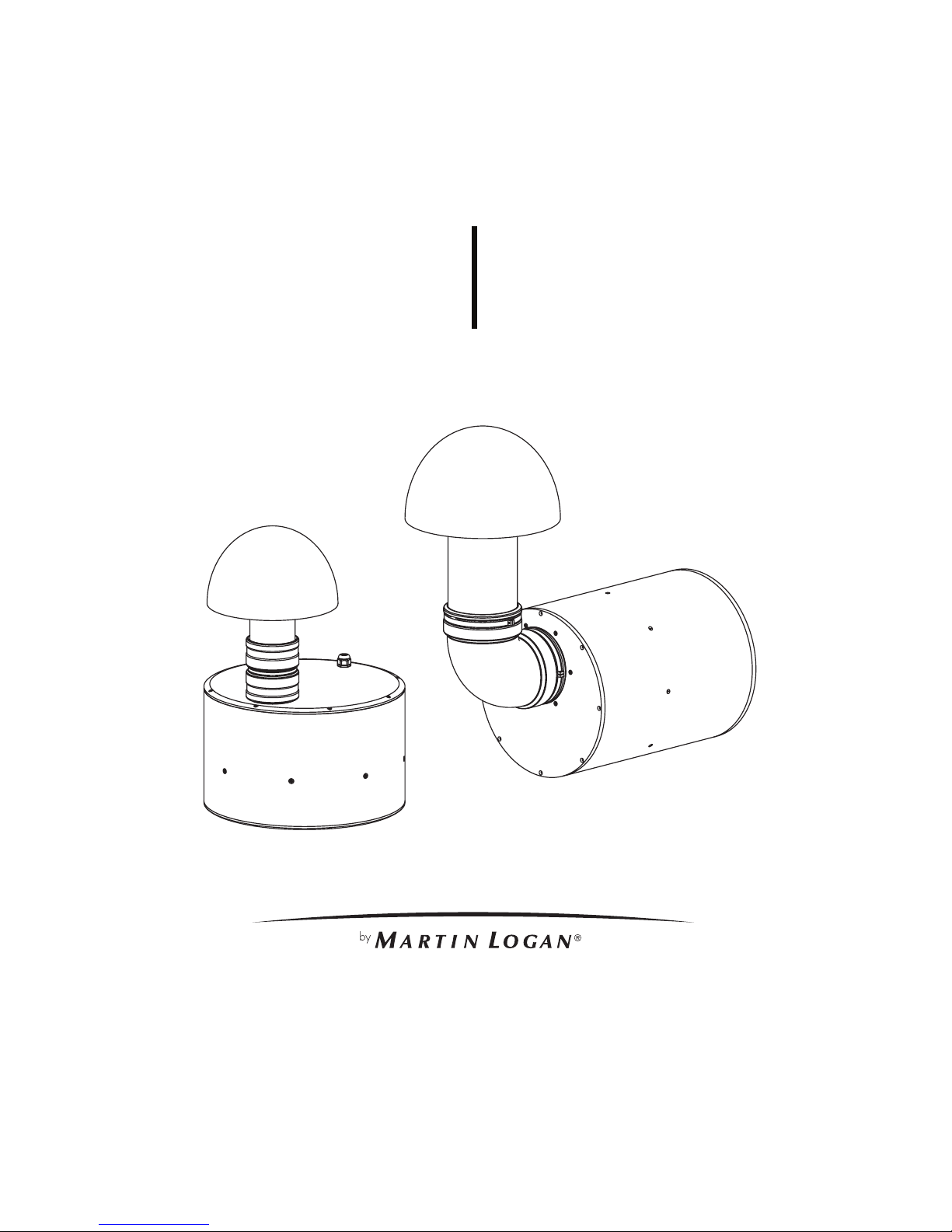
OUTDOOR LIVING SERIES
Register your warranty online at www.MartinLogan.com.
user’s manual
DYNAMO
™
OUTDOOR
SUB 100
DYNAMO
™
OUTDOOR
SUB 12 0

1

2
TABLE OF CONTENTS
Overview ...........................3
Subwoofer ...............................3
Required Tools.............................3
Power ..................................3
Planning The Install ...................4
Installation Considerations ..............5
Digging the Hole......................5
Subwoofer Assembly ..................6
Subwoofer Positioning .................6
Quantity Recommendations .............7
Wiring Recommendations ...............7
Wiring & Subwoofer Installation ..........8
Mono Setup Using 4 Conductor Burial Cable
& Crown Amplifier .......................8
Preparing the 4 Conductor Burial Cable . . . . . . . . . 8
Subwoofer & Burial Cable Connections .........9
Test System .........................9
Using Multiple Subwoofers .............10
To Avoid Subwoofer Damage ...........10
Listening Outdoors ...................10
Audio Settings Chart ..................11
Warranty ..........................12
Service............................12
Specifications .......................13
Dimensional Drawings ................14
3
OVERVIEW
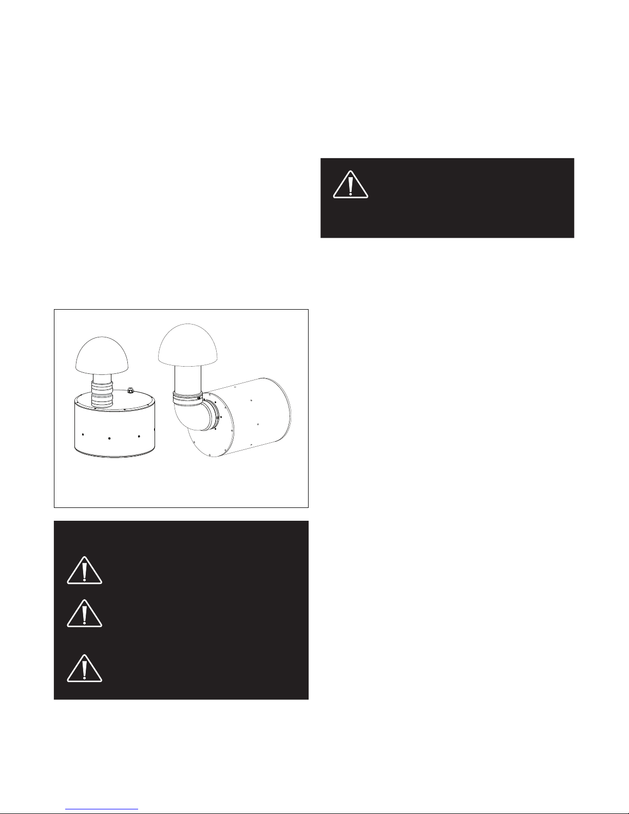
Subwoofer
The MartinLogan Outdoor Living Series
subwoofers are
weatherproof and designed to be buried at a depth of 2 feet.
The use of multiple subwoofers is recommended for larger
sized yards.
Made of durable ABS plastic, the subwoofer can endure the
elements while providing years of trouble free service.
While installation is relatively easy,
MartinLogan’
s Garden
Oasis series is designed to be installed by your authorized
MartinLogan
dealer.
WARNING!
•
ACCOUNT FOR POTENTIAL ELECTRICAL,
GAS, BURIED CABLES, PLUMBING OR
OTHER OBSTACLES BEFORE INSTALLING
GROUND STAKES.
• MANY LOCALITIES FORBID DIGGING
WITHOUT PRIOR NOTIFICATION.
CONTACT LOCAL AUTHORITIES
BEFORE INSTALLATION.
• READ AND FOLLOW all instructions
before beginning installation.
PLEASE NOTE: CONTENTS OF DYNAMO™
OUTDOOR SUB 100 ARE SHIPPED IN TWO
CARTONS. ENSURE THAT YOU HAVE BOTH
CARTONS BEFORE STARTING. Cartons are
labeled “1 of 2” and “2 of 2”.
Contents are the same for both the Dynamo™ Outdoor SUB
100 (10” Subwoofer) and Dynamo
™
Outdoor SUB 120 (12”
subwoofer).
Contents of Dynamo™ Outdoor SUB 100 and SUB 120 (1 of 2):
• (1)Subwoofer Body with Attached Cable
• (2) Silicone-Filled Wire Connectors
Contents of Box 2 (SUB 120 only):
• (1) Subwoofer Canopy
• (1) Port Tube with Compression Clamps
Required Tools:
• Shovel • Cable Strippers
• Phillips Screwdriver • Wrench
Power
• Crown CDi 1000 Amplifier
Your MartinLogan Outdoor Living Series
subwoofers
are
optimized for use with the Crown CDi 1000 amplifier which
can be programmed with customized DSP settings for a variety
of different speaker/subwoofer installation scenarios. See
‘Audio Settings Chart’ on page 11.
8 ohm amplifiers can also be used with the MartinLogan
Outdoor Living system, however, they will not be able to run
the proprietary MartinLogan DSP presets available for the
Crown Amplifier. If you use subwoofer(s) and speakers with an
8 ohm amplifier, we recommend the following. Subwoofer:
Wire only one subwoofer per amplifier channel. Satellite
Speakers: Wire only one speaker per amplifier channel and
set the tap on each speaker to the 8 ohm setting. Note: Do
not wire more than one satellite per amplifier channel in 8 ohm
mode.
DYNAMO
™
OUTDOOR
SUB 10 0
DYNAMO
™
OUTDOOR
SUB 12 0
DYNAMO
™
OUTDOOR
SUB 12 0
4
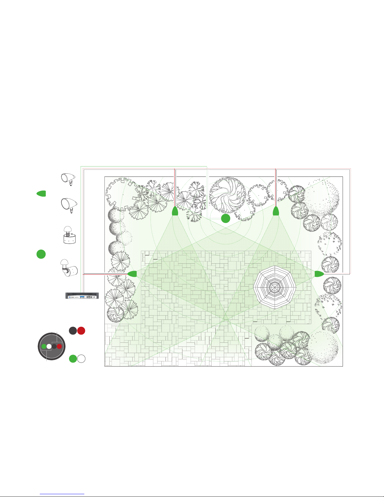
PLANNING THE INSTALL
=
=
Outdoor
SAT 40
Outdoor
SAT 60
Dynamo
Outdoor
SUB 100
Dynamo
Outdoor
SUB 120
or
or
Crown Amplifier
4 Conductor Burial Wire
Subwoofer
Speakers
–
+
–
+
Black Red
Green White
+
–
–
+
• Identify the locations and determine the positioning of
subwoofer(s) and satellite speakers. Evenly distribute
speakers and subwoofer(s) throughout the space.
• Dig the trench according to speakers and accessories to
be installed.
• The trench should be 6”–8” deep.
• If using the Crown CDi 1000 amplifier with MartinLogan
Outdoor Living presents, you can use:
o 1 to 3 subwoofers on channel 1 of the amplifier
o 1 to100 satellite speakers on channel 1 or channel 2 of
the amplifier if running 70V
o 1 to 4 satellite speakers on channel 1 or channel 2 of
the amplifier if running 8 Ohm.
5
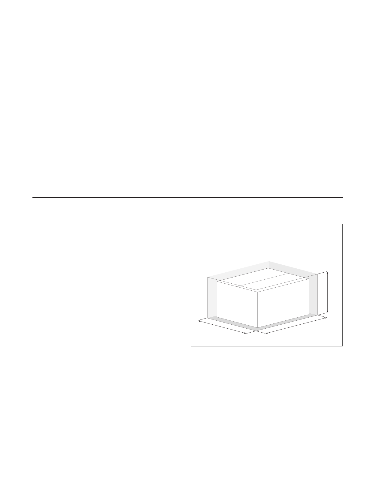
Before placing the heavy subwoofer in the hole, you can
gage the depth of the hole using the packing carton. For the
Dynamo™ Outdoor SUB 120
subwoofer carton, remember to
allow for the additional width taken up by the port elbow.
NOTE! In areas where clay or minor drainage issues are
present, place 1” of pea gravel underneath the subwoofer to
ensure proper drainage.
NOTE! Subwoofer can be positioned and operated above
ground. Stabilize the subwoofer before use.
DIGGING THE HOLE
Approximate Hole Dimensions:
Dynamo™ Outdoor SUB 100
: 26”(W) x 20”(L) x 18”(H)
Dynamo™ Outdoor SUB 120
: 30”(W) x 25”(L) x 24”(H)
(H)
(W)
(L)
16”
16”
32”
5”
There a few considerations before you start digging. We also
recommend that the Subwoofer (paired with speakers) be tested
before any trenches are dug to accommodate wiring.
Optimize Sound: Both the
Dynamo™ Outdoor SUB 100
and
Dynamo™ Outdoor SUB 120
are designed to greatly
enhance speaker performance. Each sub will perform in an
area of approximately 1,000 to 2,000 square feet.
Accessible Location: Ensure that the proposed area is
easily accessed and that the area is not prone to flooding
or standing water or where the canopy can be easily
damaged, kicked or struck.
INSTALLATION CONSIDERATIONS
6
Dynamo™ Outdoor SUB 100
Place the subwoofer into the hole, ensure there is approximately
5” between the ground level and the bottom of the canopy.
Dynamo
™
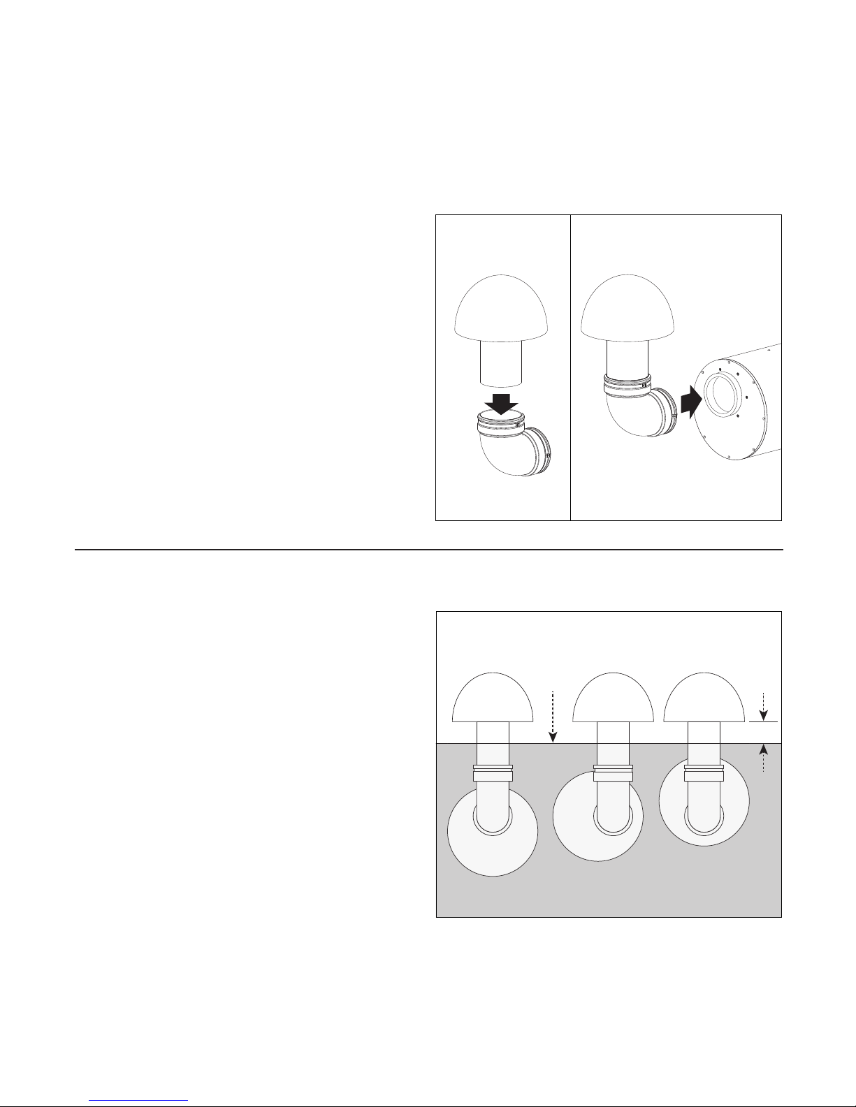
Outdoor SUB 120 (See diagram)
Place the assembled subwoofer into the hole, then rotate the
subwoofer cabinet until there is approximately 5” between
the ground level and the bottom of the canopy. Once the
positioning of the subwoofer is satisfactory, tighten the
compression clamp that holds the elbow port to the subwoofer.
IMPORTANT! Do not backfill hole until your system
is fully WIRED/tested.
Dynamo
™
Outdoor SUB 100
To assemble, place the canopy into the port tube and
tighten the compression clamp so to ensure a water
tight seal.
Dynamo™ Outdoor SUB 120 (See diagram)
Note: The port elbow is clearly marked “To Canopy” and “To
Subwoofer”.
Step 1: Insert the canopy onto the one end of the port elbow
until it is seated properly. Fully tighten the compression clamp.
Step 2: Attach the assembled canopy and elbow port to the
subwoofer, ensuring that dirt and other debris do not enter the
port tube. Do not fully tighten the compression clamp that holds
the elbow port to the subwoofer.
Shown: Dynamo™
Outdoor SUB 120
SUBWOOFER ASSEMBLY
SUBWOOFER POSITIONING
Ground
Level
Example 1
Example 2
Example 3
5”
Shown: Dynamo™
Outdoor SUB 120
Step 1 Step 2

7
We strongly recommend using burial-rated cable (not
included) when installing any of the Outdoor Living Series
subwoofers. In addition, it’s critical to use the proper speaker
cable gauge. Please review the chart below.
We do not recommend use of high gauge wires, as
performance will be compromised.
WIRING RECOMMENDATIONS
CABLE GAUGE CHART
Total Wire Length 70 Volt 8 Ohm
0–100 feet
(0–30 meters)
18 gauge
or lower
14 gauge
or lower
100+ feet
(30+ meters)
16 gauge
or lower
12 gauge
or lower
QUANTITY RECOMMENDATIONS
USAGE CHART
Product Use 1x per
SAT 40
or SAT 60
250–500
square feet
SUB 100
or SUB 120
1000–2000
square feet
8
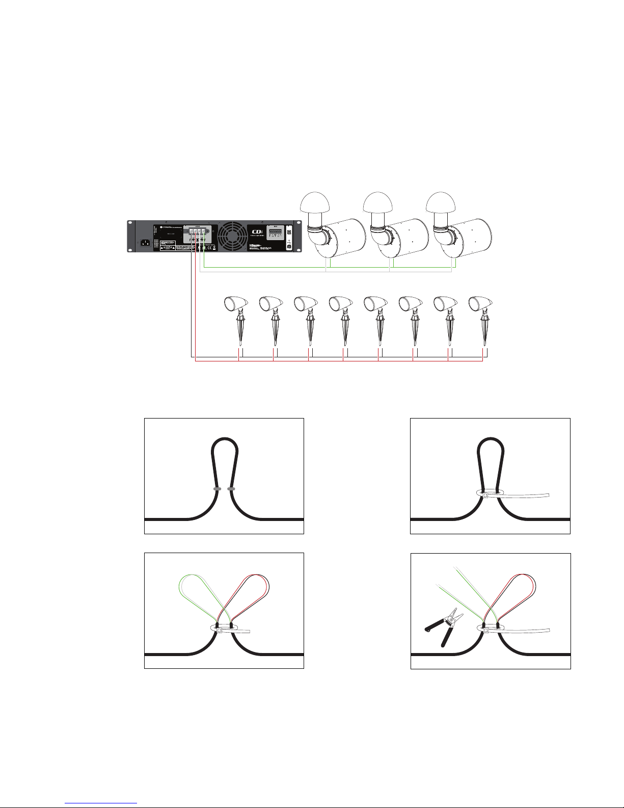
Mono Setup Using 4 Conductor Burial Cable & Crown Amplifier
Preparing the 4 Conductor Burial Cable
WIRING & SUBWOOFER INSTALLATION
1. Starting with
the first speaker
and every
speaker/sub
that comes after,
create a loop
approximately
6” in length.
3. Use a Round
Cable Stripper
to remove
the outside
protective cable
jacket to expose
the four colorcoded wires.
Separate the
wire loops as
shown.
2. Recommended:
Use a wire tie
(not included) to
keep the wire
loop intact and
act as a strain
relief.
4. Cut the white (+)
and green (-)
wires with cable
strippers and
strip off 1 inch
(25.4mm) of
insulation from
the ends of the
wires to expose
the copper
conductor.
Wires for
Subwoofer
green (+) &
white (-)
Wires for
Speaker
red (+) &
black (-)
MonoMonoMonoMonoMonoMonoMonoMono
SAT 40 OR SAT 60 (70V or 8-Ohm)
SUB 100 OR SUB120 (8 Ohm)
Speakers and subs should be
wired in parallel, not series.
9
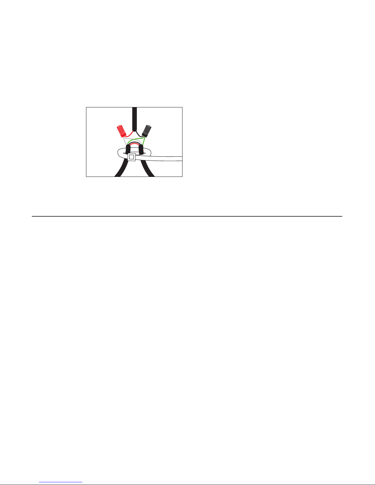
Subwoofer & Burial Cable Connections
Combine and twist
(clockwise) the red
wires (as shown
in the diagram)
from the amp, the
subwoofer and
to the adjoining
speaker. Secure
these three cables
using the provided
silicone-filled wire
connectors; Repeat procedure for Black wires. NOTE: You
may have to cut some of the speaker cable emanating from
the subwoofer to a more manageable size.
WIRING & SPEAKER INSTALLATION (CONT’D)
To Subwoofer
To Amp
To Adjoining
Speaker
TEST SYSTEM
After all subwoofer and satellite connections are completed,
connect the wires to your receiver or amplifier.
IMPORTANT! Be sure not to let any stray’+’ and’-’
strands touch each other. Touching strands will cause
a short circuit which could damage your amplifier.
Turn your receiver or amplifier ‘On’ and test the system with your
favorite music. If the speakers are operating properly, refill the
wire trench and enjoy your new subwoofers.
 Loading...