


SL-3
Table of contents
 Loading...
SL3
TM
user’s manual
c l s e l e c t r o s t a t i c
M ARTIN L OGAN

2 Contents
CONTENTS
Contents . . . . . . . . . . . . . . . . . . . . . . . . . . . . . . . . . . . . . .2
Installation in Brief . . . . . . . . . . . . . . . . . . . . . . . . . . . . .3
Introduction . . . . . . . . . . . . . . . . . . . . . . . . . . . . . . . . . . .4
Operation . . . . . . . . . . . . . . . . . . . . . . . . . . . . . . . . . . . . .5
AC Power Connection
Signal Connection
Break-In
Jumper Clips
Single-Wire Connection
Bi-Wire Connection
Passive Bi-Amplification
Bass Control Switch
Placement . . . . . . . . . . . . . . . . . . . . . . . . . . . . . . . . . . . . .8
Listening Position
The Wall Behind the Listener
The Wall Behind the Speakers
The Side Walls
Experimentation
Final Placement
The Extra “Tweak”
Enjoy Yourself
Room Acoustics . . . . . . . . . . . . . . . . . . . . . . . . . . . . . . .10
Your Room
Terminology
Rules of Thumb
Dipolar Speakers and Your Room
Solid Footing
Dispersion Interactions . . . . . . . . . . . . . . . . . . . . . . . . .12
Controlled Horizontal Dispersion
Controlled Vertical Dispersion
Three Major Types of Dispersion
Home Theater . . . . . . . . . . . . . . . . . . . . . . . . . . . . . . . .14
Electrostatic Advantages . . . . . . . . . . . . . . . . . . . . . . . .15
Full Range Operation
MartinLogan Exclusives . . . . . . . . . . . . . . . . . . . . . . . . .17
Curvilinear Line Source
Vapor Deposited Film
Transducer Integrity
Electrostatic Loudspeaker History . . . . . . . . . . . . . . . .18
Frequently Asked Questions . . . . . . . . . . . . . . . . . . . . .20
Troubleshooting . . . . . . . . . . . . . . . . . . . . . . . . . . . . . . .22
General Information . . . . . . . . . . . . . . . . . . . . . . . . . . .23
Specifications
Warranty and Registration
Service
Glossary of Audio Terms . . . . . . . . . . . . . . . . . . . . . . . .24
Notes . . . . . . . . . . . . . . . . . . . . . . . . . . . . . . . . . . . . . . . .26
3Installation in Brief 3
INSTALLATION IN BRIEF
We know you are eager to hear your new SL3 loudspeakers,
so this section is provided to allow fast and easy set up.
Once you have them operational, please take the time to
read, in depth, the rest of the information in this manual.
It will give you perspective on how to attain the greatest
possible performance from this most exacting transducer.
If you should experience any difficulties in the setup or
operation of your SL3 speakers, please refer to the Room
Acoustics, Placement or Operation sections of this manual.
Should you encounter a persistent problem that cannot be
resolved, please contact your authorized MartinLogan
dealer. They will provide you with the appropriate technical
analysis to alleviate the situation.
WARNING!
•Hazardous voltages exist inside—do not
remove cover
•Refer servicing to a qualified technician
•To prevent fire or shock hazard, do not
expose this module to moisture
•Turn amplifier off and unplug speaker
should any abnormal conditions occur
•Do not operate if there is any visual
damage to the electrostatic panel element
•Do not over drive speaker beyond its rated power
Step 1: Unpacking
Remove your new SL3 speakers from their packing.
Step 2: Placement
Place each SL3 at least two feet from any wall and angle
them slightly toward your listening area. This is a good
place to start. Please see the Placement section (pages 8–9)
of this manual for more details.
Step 3: Power Connection (AC) (see warning)
MartinLogan speakers require AC power to energize their
electrostatic cells. Using the AC power cords provided,
plug them in
first to the AC power receptacle on the rear
panel of the speaker
, making sure that you have made a
firm
connection, and then to the wall outlet. Please see
the Operations section (pages 5–7) of this manual for
more details.
Step 4: Signal Connection
Use the best speaker cables you can. Higher quality cables,
available from your specialty dealer, are recommended
and will give you superior performance. Spade connectors
are suggested for optimum contact and ease of installation.
Attach your speaker cables to the Signal Input section on
the rear panel. Be consistent when connecting speaker
leads to the terminals on the back of the SL3: take great
care to assign the same color to the (+) terminal on both
the left and right channels. If bass is nonexistent and you
cannot discern a tight, coherent image, you may need
to reverse the (+) and (-) leads on one side to bring the
system into proper polarity.
For Bi-wiring/Passive Bi-amping instructions, turn to the
Operations section (Page 5–7) of this manual for proper
setup of the SL3 system.
Step 5: Listen and Enjoy
Now, you may turn on your system and enjoy!
The lightning bolt flash with arrowhead symbol, within
an equilateral triangle, is intended to alert the user to
the presence of uninsulated “dangerous voltage” within the
product’s enclosure that may be of sufficient magnitude
to constitute a risk of electric shock.
The exclamation point within an equilateral triangle is
intended to alert the user to the presence of important
operating and maintenance (servicing) instructions in
the literature accompanying the appliance.

4 Introduction
INTRODUCTION
Congratulations! You have invested in one of the world’s
premier loudspeaker systems.
The MartinLogan SL3 represents the culmination of an
intensive, dedicated group research program directed
toward establishing a world class reference monitor
utilizing leading-edge technology, without compromising
durability, reliability, craftsmanship or aesthetic design.
The SL3 raises and refines the performance level of the
original MartinLogan Sequel II while reducing the space it
consumes in your home. Bass response now has better
extension and improved definition. High frequency
response also has better extension and is more natural in
character. The integration of the two is much smoother
and seamless. Power handling and system efficiency have
been enhanced as well.
The materials in your new SL3 speakers are of the highest
quality and will provide years of enduring enjoyment and
deepening respect. All trim pieces are constructed from
selected hardwoods. They are then grain and color
matched
and finally hand finished. The cabinetry is constructed from
the highest quality composite material for acoustical integrity
and is finished with our attractive custom matte finish.
Through rigorous testing, the curvilinear electrostatic panel
has proven itself to be one of the most durable and reliable
transducers available today. Fabricated from a custom tool
punched high-grade steel, the patented panel is then coated
with a special polymer that is applied via a proprietary electrostatic
deposition process. This panel assembly houses a membrane
just 0.0005 of an inch thick. Ruggedly constructed and
insulated, as much as 200 watts of continuous power has
driven the SL3’s energized diaphragm into massive excursions
with no deleterious effects.
The other sections of your User’s Manual will explain in
detail the operation of your SL3 speakers and the philosophy
applied to their design. A clear understanding of your
speakers will insure that you obtain maximum performance
and pleasure from this most exacting transducer. It has been
designed and constructed to give you years of trouble-free
listening enjoyment.
OPERATION
Operation 5
Because your MartinLogan SL3s use an internal power supply
to energize their electrostatic cells with high-voltage DC,
they must be connected to an AC power source. For this
reason they are provided with the proper IEC standard
power cords. These cords should be firmly inserted into
the AC power receptacles on the rear connection panel of
the speakers, then to any convenient AC wall outlet. The SL3s
integrate a signal sensing power supply which will switch
off after a few minutes of no music signal, and requires
less than two seconds to recharge the panels when a
music signal is present.
Your SL3 speakers are wired for the power service supplied
in the country of original consumer sale. The AC power
rating applicable to a particular unit is specified both on
the packing carton and on the serial number plate
attached to the speaker.
If you remove your SL3 speakers from the country
of original sale, be certain that AC power supplied in any
subsequent location is suitable before connecting and
operating the speakers. Substantially impaired performance
or severe damage may occur to an SL3 speaker if operation
is attempted from an incorrect AC power source.
WARNING! The power cord should not be installed,
removed, or left detached from the speaker while
the other end is connected to an AC power source.
Signal Connection
Use the best speaker cables you can. The length and type of
speaker cable used in your system will have an audible
effect. Under no circumstance should a wire of gauge higher
(thinner) than #16 be used. In general, the longer the length
used, the greater the necessity of a lower gauge, and the
lower the gauge, the better the sound, with diminishing
returns setting in around #8 to #12.
A variety of speaker cables are now available whose
manufacturers claim better performance over standard
heavy gauge wire. We have verified this in many cases, and
the improvements available are often more noticeable
than the differences between wires of different gauge. The
effects of cables may be masked if the equipment is not of
the highest quality.
We also recommend, if possible, that short runs of speaker
cable connect the power amplifier(s) and speakers and that
high quality long interconnect cables be used to connect
the preamplifier and power amplifier. This results in the
power amplifiers being close to the speakers, which may
be practically or cosmetically difficult, but if the length of
the speaker cables can be reduced to a few meters, sonic
advantages may be obtained.
Connections are done at the Signal Input section on the
rear electronics panel of the SL3. Use spade connectors
for optimum contact and ease of installation. Make certain
that all of your connections are tight.
Be consistent when connecting the speaker cables to the
Signal Input terminals. Take care to assign the same color
cable lead to the (+) terminal on both the left and right
channel speakers. If bass is nonexistent and you cannot
discern a tight, coherent image, you may need to reverse
the (+) and (-) leads on one speaker to bring the system
into proper polarity.
WARNING! Turn your amplifier off before making
or breaking any signal connections!
Break-In
When you first begin to play your SL3 speakers, they will
sound a bit bass shy. This is due to the high-quality, longlife components used in our woofer. Our custom made,
butyl surround woofer requires 30 hours of break-in at 90
dB (moderate listening levels) before any critical listening.
The break-in requirements of the crossover components
(and, to a lesser degree, the stator) are equivalent.
Jumper Clips
In some countries federal law prohibits MartinLogan from
supplying jumper clips. If none are found installed under
your speakers binding posts, please refer to ‘Bi-Wire
Connection’ for connection instructions. If jumper clips
are installed please refer to ‘Single-Wire Connection’ for
connection instructions.
AC Power Connection
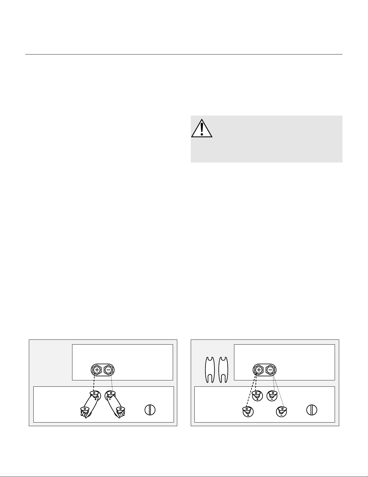
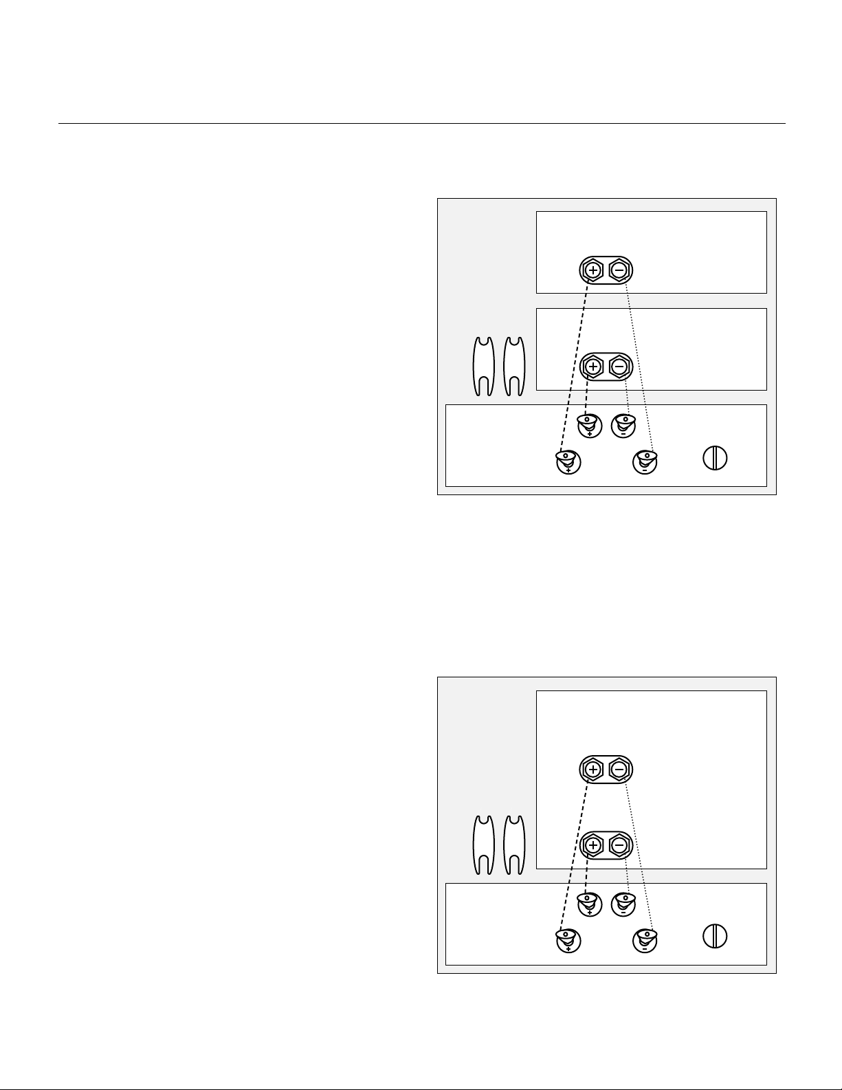
Figure 2. Bi-Wire Connection. One Channel shown.
Amplifier
speaker output
Jumper clips
removed
Please take note of the jumper clips installed under the
binding posts. These clips attach the high and low frequency
sections of the crossover together. Leaving these in place,
connect the (+) wire from your amplifier to either red
binding post and the (-) wire from your amplifier to either
black binding post (See Figure 1).
Bi-Wire Connection
This method of connection replaces the jumper clips installed
under the binding posts with individual runs of speaker
wire from your amplifier. This doubles the signal carrying
conductors from the amplifier to the speaker, thus directcoupling each portion of the crossover to the amplifier.
To bi-wire you must first loosen the binding posts and
remove the jumper clips. Connect one set of wires to the
upper set of binding posts which connect to the panel of
the SL3. Then connect a second set of wires to the lower
binding posts which connect to the woofer. Next, connect
both sets of wires to the appropriate terminals on your
amplifier. Please take care to connect both (+) wires to
the (+) amplifier terminals and both (-) wires to the (-)
amplifier terminals. This is known as a parallel connection
(See Figure 2).
For those of you that desire ultimate performance, the SL3
may be passively bi-amplified using the existing internal
passive crossover elements.
WARNING! Only after the jumper clips are removed
may you connect individual runs of speaker cable
from your amplifiers to the high pass (ESL) and
low pass (WOOFER) Signal Input binding posts.
Damage will occur to your amplifiers if the jumper
clips are not removed.
This method takes the bi-wiring concept one step further.
Now you will have a dedicated channel of amplification
directly connected to the high and low pass sections of the
SL3 crossover. There are two different methods for bi-amping
with two stereo amplifiers. The first and most common is
referred to as Horizontal Bi-amping. The second method
is referred to as Vertical Bi-amping. With either method
you may use two stereo amplifiers or four mono amplifiers,
or two mono amplifiers and one stereo amplifier. Get the idea?
With either form of passive bi-amplification, your preamplifier
must have dual outputs. If your preamplifier is not so equipped,
you must either purchase or construct a “Y” adapter.
Horizontal Passive Bi-Amplification
Horizontal bi-amping allows you to use two different types,
models or brands of amplifiers (i.e. tubes on top, transistor
on the bottom). However, we recommend that you use
two identical amplifiers (i.e. same brand and model).
If you must use two different amplifiers, it is essential that
they have the same gain or that one of the two have adjustable
gain so that you can match their gain characteristics.
If the amplifiers of choice do not have the same gain
characteristics, then a sonic imbalance will occur.
Single-Wire Connection
Figure 1. Single-Wire Connection. One Channel shown.
SL3
TM
Loud Speaker
Amplifier
Jumper clips
in place,
full-range
speaker output
Passive Bi-Amplification
SL3
TM
Loud Speaker
ESL
Woofer
ESL
Woofer
Bass Control
flat
reduce
Bass Control
flat
reduce
6 Operations
With horizontal bi-amping, one amplifier drives the high
pass (ESL) section while the second amplifier drives the
low pass (WOOFER) section. To horizontally bi-amp your
SL3s you must loosen the binding posts and remove the
jumper clips. Connect the low frequency amplifier to the
lower set of binding posts of both speakers. Connect the
high frequency amplifier to the upper set of binding posts.
Next, connect the left and right preamplifier outputs to the
appropriate left and right inputs of both amplifiers (See
Figure 3).
Vertical Passive Bi-Amplification
The very nature of vertical bi-amping dictates that both
amplifiers be identical. With vertical bi-amping, each of
the stereo amplifiers is dedicated to one speaker. For
instance, the left channel of each amplifier drives the low
pass (WOOFER) section while the right channel drives the
high pass (ESL) section. To vertically bi-amp your SL3s you
must loosen the binding posts and remove the jumper
clips from both speakers. Starting with one speaker, connect
the right channel to the lower binding posts and the left
channel to the upper binding posts. Repeat the same procedure
for the other speaker. Connect the left preamplifier outputs
to both inputs of the left channel amplifier and the right
preamplifier outputs to both inputs of the right channel
speaker (See Figure 4).
Bass Control Switch
On the rear panel of the SL3 electronics module, beside
the Signal Input binding posts, is a two position Bass Control
switch that allows you to select the type of low frequency
response you desire.
The 0 dB position is considered the normal setting for most
rooms. However, if you feel that the bass in your system
is too heavy relative to the mid and high frequencies,
simply select the -3 dB position. This switch position will
decrease the output of the woofer by 3 dB.
Some experimentation with these two switch settings will
allow you to find the optimal tonal balance for your specific
taste, room and equipment.
Figure 3. Horizontal passive bi-amplification. One Channel shown.
High Amplifier
speaker output
Low Amplifier
speaker output
ESL
Woofer
Jumper clips
removed
Figure 4. Vertical passive bi-amplification. One Channel shown.
Left Channel Amplifier
speaker output
ESL
Woofer
Jumper clips
removed
SL3
TM
Loud Speaker
SL3
TM
Loud Speaker
Operation 7
Bass Control
flat
reduce
Bass Control
flat
reduce

8 Placement
PLACEMENT
By now your speakers should be placed approximately
two to three feet from the front wall, the wall in front of
the listening position, and at least one to two feet from
the side walls. Your sitting distance should be further
than the distance between the speakers themselves. What you
are trying to attain is the impression of good center imaging
and stage width.
There is no exact distance between speakers and listener,
but there is a relationship. In long rooms, naturally, that
relationship changes. The distance between the speakers
will be far less than the distance from you to the speaker
system. However, in a wide room, you will still find that if
the distance from the listener to the speakers becomes
smaller than the distance between the speakers themselves,
the image will no longer focus in the center.
Now that you have positioned your speaker system, spend
some time listening. Wait to make any major changes in
your initial setup for the next few days as the speaker
system itself will change subtly in its sound. Over the first
40 hours of play the actual tonal quality will change slightly
with deeper bass and more spacious highs resulting.
After a few days of listening you can begin to make refinements
and hear the differences of those refinements.
The Wall Behind the Listener
Near-field reflections can also occur from your back wall
(the wall behind the listening position). If your listening
position is close to the back wall, these reflections can
cause problems and confuse the quality of imaging.
Actually it is better for the wall behind you to be soft
than to be bright. If you have a hard back wall and your
listening position is close to it, experiment with devices
that will soften and absorb information (i.e. wall hangings
and possibly even sound absorbing panels).
The Wall Behind the Speakers
The front surface, the wall behind your speakers, should not
be extremely hard or soft. For instance, a pane of glass
will cause reflections, brightness and confused imaging.
Curtains, drapery and objects such as bookshelves can
be placed along the wall to soften a hard surface. A standard
sheet rock or textured wall is generally an adequate
surface if the rest of the room is not too bright and hard.
Sometimes walls can be too soft. If the entire front wall
consists of only heavy drapery, your system can sound too
soft or dull. You may hear dull, muted music with little
ambience. Harder room surfaces will actually help in this case.
The front surface should, optimally, be one long wall
without any doors or openings. If you have openings, the
reflection and bass characteristics from one channel to the
other can be different.
The Side Walls
The same requirements exist for side walls. Additionally, a
good rule of thumb is to have the side walls as far away
from the speaker sides as possible, minimizing near-field
side wall reflections. Sometimes, if the system is bright or
the imaging is not to your liking, and the side walls are
very near, try putting curtains or softening material directly
to the edge of each speaker. An ideal side wall, however,
is no side wall at all.
Experimentation
Toe-in
Now you can begin to experiment. First begin by toeing
your speakers in towards the listening area and then facing
them straight into the room. You will notice that the tonal
balance changes slightly. You will also notice the imaging
changing. Generally it is found that the ideal listening
position is with the speakers slightly toed-in so that you are
listening to the inner third of the curved transducer section.
Experimenting with the toe-in will help in terms of tonal
balance. You will notice that as the speakers are toed-out,
the system becomes slightly brighter than when toed-in.
This design gives you the flexibility to compensate for a
soft or bright room.
Tilting the Speakers Backwards and Forwards
As can be seen from the diagrams in the Room Acoustics
section of this manual, the vertical dispersion is directional
above and below the stator panel itself. In some instances, if
you are sitting close to the floor, slight forward tilting of the
speakers can enhance clarity and precision.
Listening Position

Placement 9
Imaging
In their final location, your SL3s should have a stage width
somewhat wider than the speakers themselves. On well
recorded music, the instruments should extend beyond
the edges of each speaker to the left and to the right, yet a
vocalist should appear directly in the middle. The size of
the instruments should be neither too large nor too
small. Additionally, you should find good clues as to stage
depth. Make sure that the vertical alignment, distance
from the front wall, and toe-in, is exactly the same from
one speaker to the other. This will greatly enhance the
quality of your imaging.
Bass Response
Your bass response should neither be one note nor should
it be too heavy. It should extend to even the deepest organ
passages, yet it should be tight and well defined. Kick-drums
should be tight and percussive—string bass notes should
be uniform and consistent throughout the entirety of the
run without any booming or thudding.
Tonal Balance
Voices should be natural and full, cymbals should be
detailed and articulate yet not bright and piercing, pianos
should have a nice transient characteristic and deep tonal
registers as well. If you cannot attain these virtues, read the
section on Room Acoustics (pages 10–11). This will give
you clues on how to get closer to those ideal virtues.
Final Placement
After obtaining good wall treatments and attaining proper
angle, begin to experiment with the distance from the wall
behind the speakers. Move your speaker slightly forward
into the room. What happened to the bass response?
What happened to the imaging? If the imaging is more
open and spacious and the bass response is tightened, that
is a superior position. Move the speakers back six inches
from the initial setup position and again listen to the imaging
and bass response. There will be a position where you will
have pinpoint imaging and good bass response. That position
is the point of the optimal placement from the front wall.
Now experiment with placing the speakers farther apart.
As the speakers are positioned farther apart, listen again,
not so much for bass response but for stage width and
good pinpoint focusing.
Your ideal listening position and speaker position will
be determined by:
•Tightness and extension of bass response
•Width of the stage
•Pinpoint focusing of imaging
Once you have determined the best of all three of these
considerations, you will have your best speaker location.
The Extra “Tweak”
A major cable company developed the following procedure
for speaker placement. As a final test of exact placement,
use these measurements for your speakers placement, and
see what can happen to the ultimate enhancement of
your system’s performance. These two basic formulas will
determine optimum placement of your speakers to minimize
standing waves.
1. Distance from the front wall (the wall in front of the listening
position) to the center of the curvilinear transducer. To
determine distance from the front wall, measure the height
of your ceiling (inches) and multiply the figure by 0.618
(i.e. ceiling height in inches x 0.618 = the distance from
the front wall to the center of the curvilinear transducer).
2. Distance from the side-walls to the center of the curvilinear
transducer. To determine distance from the side walls,
measure the width of your room in inches and divide
by 18. Next, multiply the quotient by 5 (i.e. room width
in inches/18] x 5 = the distance from the side-walls to
the center of the curvilinear transducer).
Enjoy Yourself
The SL3 is a very refined speaker and benefits from care
in setup. With these tips in mind you will find, over your
months of listening, that small changes can result in
measurable differences. As you live with your speakers, do
not be afraid to experiment with their positioning until
you find the optimal relationship between your room and
speaker system that gives to you the best results. Your efforts
will be rewarded.
You are now armed with the fundamental knowledge of
room acoustics and the specific fundamentals of the SL3
loudspeaker. Happy listening!
Loading...