

MartinLogan Speaker, Spire User Manual

S p i r e
tm
u s e r ’ s m a n u a l
Serial Numbers: ________________ / ________________
Record your serial numbers here for easy reference. You will need this
information when filling out your warranty registration. Spire’s serial number is located near the bottom of the backplate and on the shipping container. Each individual unit has a unique serial number.
35Hz Setting: ________________ / ________________
left channel right channel
Spire
Tested to Comply
with FCC Standards
FO R HO ME O R OF FI CE U SE
This device complies with part 15 of
the FCC Rules. Operation is subject
to the following two conditions: (1)
This device may not cause harmful
interference, and (2) this device must
accept any interference received,
in cluding interference that may
cause undesired operation.

Thank you—to you the MartinLogan owner,
for loving what we do,
and
for making it possible for us to do what we love.
Contents
Contents . . . . . . . . . . . . . . . . . . . . . . . . . . . . . . . . . . . . . . 4
Installation in Brief . . . . . . . . . . . . . . . . . . . . . . . . . . . . . 5
Introduction . . . . . . . . . . . . . . . . . . . . . . . . . . . . . . . . . . . 6
Controls and Connections . . . . . . . . . . . . . . . . . . . . . . . 7
AC Power Connection . . . . . . . . . . . . . . . . . . . . . . . . . . . 8
Signal Connection
Break-In
Jumper Clips
Single-Wire Connection . . . . . . . . . . . . . . . . . . . . . . . . . 9
Bi-Wire Connection
Bi-Amplification
35Hz Level Control
Placement. . . . . . . . . . . . . . . . . . . . . . . . . . . . . . . . . . . . 11
Listening Position
The Wall Behind the Listener
The Wall Behind the Speakers
The Side Walls
Experimentation
Final Placement . . . . . . . . . . . . . . . . . . . . . . . . . . . . . . . 12
The Extra “Tweak”
Enjoy Yourself
Room Acoustics . . . . . . . . . . . . . . . . . . . . . . . . . . . . . . . 13
Your Room
Terminology
Rules of Thumb
Dipolar Speakers and Your Room . . . . . . . . . . . . . . . . . 14
Solid Footing
Dispersion Interactions. . . . . . . . . . . . . . . . . . . . . . . . . 15
Controlled Horizontal Dispersion
Controlled Vertical Dispersion
Three Major Types of Dispersion
Home Theater. . . . . . . . . . . . . . . . . . . . . . . . . . . . . . . . . 16
Electrostatic Advantages . . . . . . . . . . . . . . . . . . . . . . . . 17
Full Range Operation. . . . . . . . . . . . . . . . . . . . . . . . . . . 18
MartinLogan Exclusives . . . . . . . . . . . . . . . . . . . . . . . . . 19
XStat™ Transducer
CLS™ (Curvilinear Line Source)
Generation 2 Diaphragm
MicroPerf Stator
Vacuum Bonding
AirFrame™ Technology
PoweredForce™ Bass Technology
Electrostatic Loudspeaker History . . . . . . . . . . . . . . . . 20
Frequently Asked Questions. . . . . . . . . . . . . . . . . . . . . 22
Troubleshooting. . . . . . . . . . . . . . . . . . . . . . . . . . . . . . . 24
General Information . . . . . . . . . . . . . . . . . . . . . . . . . . . 25
Specifications
Warranty and Registration
Serial Number
Service
Dimensional Drawings . . . . . . . . . . . . . . . . . . . . . . . . . 26
Glossary of Audio Terms . . . . . . . . . . . . . . . . . . . . . . . . 27
In accordance with the European Union WEEE (Waste Electrical
and Electronic Equipment) directive effective August 13, 2005,
we would like to notify you that this product may contain regulated materials which upon disposal, according to the WEEE
directive, require special reuse and recycling processing.
The lightning bolt flash with arrowhead symbol, within
an equilateral triangle, is intended to alert the user to
the presence of uninsulated “dangerous voltage” within
the product’s enclosure that may be of sufficient magnitude to constitute a risk of electric shock.
The exclamation point within an equilateral triangle is
intended to alert the user to the presence of important
operating and maintenance (servicing) instructions in
the literature accompanying the appliance.
WARNING! Do not use your Spire loudspeakers outside of the country of original sale—voltage requirements
vary by country. Improper voltage can cause damage that will be potentially expensive to repair. The Spire is
shipped to authorized MartinLogan distributors with the correct power supply for use in the country of intended
sale. A list of authorized distributors can be accessed at www.martinlogan.com or by emailing info@martinlogan.com.
4 Contents
For this reason MartinLogan has arranged with our distributors
in European Union member nations to collect and recycle this
product at no cost to you. To find your local distributor please
contact the dealer from whom you purchased this product,
email info@martinlogan.com or visit the distributor locator at
www.martinlogan.com.
Please note, only this product itself falls under the WEEE
directive. When disposing of packaging and other related
shipping materials we encourage you to recycle these items
through the normal channels.

InstallatIon In BrIef
We know you are eager to hear your Spire speakers, so
this section is provided to allow fast and easy set up. Once
you have them operational, please take the time to read,
in depth, the rest of the information in this manual. It will
give you perspective on how to attain the greatest possible
performance from this most exacting transducer.
If you should experience any difficulties in the setup or
operation of your Spire speakers, please refer to the Room
Acoustics, Placement or Operation sections of this manual.
Should you encounter a persistent problem that cannot
be resolved, please contact your authorized MartinLogan
dealer. They will provide you with the appropriate technical
analysis to alleviate the situation.
WARNING!
• Hazardous voltages exist inside—do not
remove cover.
• Refer servicing to a qualified technician.
• To prevent fire or shock hazard, do not
expose this module to moisture.
• Turn amplifier off and unplug speaker should
any abnormal conditions occur.
• Turn amplifier off before making or breaking
any signal connections!
• Do not operate if there is any visual damage
to the electrostatic panel element.
• Do not drive speaker beyond its rated power.
• The power cord should not be installed,
removed, or left detached from the speaker
while the other end is connected to an AC
power source.
• Use only with a grounded electrical outlet.
• No candles or other sources of open flame
should be placed on the speaker.
• No liquids either in glasses or vases should be
placed on speaker.
• Speaker should not be exposed to dripping or
splashing liquids.
• The terminals marked with the lightning bolt
symbol should be connected by an instructed
person or by way of ready made terminals.
• The power cord should remain readily operable should any abnormal conditions occur.
Step 1: Unpacking
Remove your new Spire speakers from their packaging.
Step 2: Placement
Place each Spire at least two feet from the back wall and
angle them slightly toward your listening area. This is a good
place to start. Please see the Placement section (pages 11–
12) of this manual for more details.
Step 3: Power Connection (AC) (see warning)
Your Spire speakers require AC power to energize their
electrostatic cells and to power the PoweredForce™ woofer.
Using the AC power cords provided,
the AC power receptacle on the rear panel of the speaker
making sure that you have made a firm
then to a wall outlet. Please see AC Power Connection
(pages 8) of this manual for more details.
Step 4: Signal Connection
Use the best speaker cables you can. Higher quality cables,
available from your specialty dealer, are recommended
and will give you superior performance. Spade connectors
are suggested for optimum contact and ease of installation.
Attach your speaker cables to the signal input section on the
rear panel. Be consistent when connecting speaker leads to
the terminals on the back of the Spire. Take great care to
assign the same color to the (+) terminal on both the left and
right channels. If bass is nonexistent and you cannot discern
a tight, coherent image, you may need to reverse the (+) and
(–) leads on one side to bring the system into proper polarity.
For detailed setup instructions, please turn to the Controls
and Connections section (Page 7–10) of this manual for
more details.
Step 5: Control Settings
Set the 35Hz Bass Level Control knobs to 0dB. Please
see 35Hz Level Control (page 7) of this manual for more
details.
Step 6: Listen and Enjoy
Now, you may turn on your system and enjoy!
plug them in
connection, and
first to
,
Installation in Brief 5

IntroduCtIon
Congratulations! You have invested in one of the world’s
premier loudspeaker systems.
Th e MartinLogan Spire™ represents an advanced
combination of sonic technologies establishing an unprecedented direction for audiophile design. The result of
years of research, the new Spire™ hybrid electrostatic loudspeaker features PoweredForce™ and XStat™
technologies, dramatically reducing cabinet size, yet
establishing new standards for efficiency, dynamics and
precision in a floorstanding loudspeaker.
The luminous legacy of MartinLogan subwoofer engineering and research not only produced some of the
world’s most sophisticated subwoofers, but has also
yielded new breakthroughs. Through integrated engineering of advanced amplification and transducer designs,
PoweredForce™ bass technology results in usable bass
extension down to 29Hz, immense bass dynamics and
precision beyond the reach of traditional passive box systems—all from an enclosure not much larger than a case of
wine! Additionally, low-frequency equalization capabilities, integrated into advanced PoweredForce™ technology,
allow precision calibration for optimal room integration.
Housed within a radical, ultra-rigid extruded aluminum
AirFrame™, the Spire’s™ CLS XStat™ transducer builds
upon the legacy of MartinLogan’s electrostatic heritage
with the incorporation of advanced vacuum bonding and
MicroPerf stat panels, providing even greater efficiency and
precision. The integration electrical interface technology
developed by MartinLogan’s Statement™ e2 engineering
team extends effortless dynamics and purity, resulting in
even higher sonic standards of efficiency and precision.
Featuring an advanced crossover topology derived from
the Statement™ loudspeaker, MartinLogan carefully
hand-builds each Spire™ crossover utilizing precision
point-to-point wiring, audiophile-grade polypropylene
capacitors and high-purity air-core coils. This advanced
crossover topology flawlessly preserves microscopic subtleties while effortlessly handling the broadest range of
dynamics contained within even the most demanding
sonic source.
The materials in your new Spire speakers are of the highest
quality and will provide years of enduring enjoyment
and
deepening respect. The cabinetry is constructed
from the highest quality composite material for acoustical
integrity and features hand rubbed wood veneers.
Through rigorous testing, the curvilinear electrostatic
panel has proven itself to be one of the most durable and
reliable transducers available today. Fabricated from a
custom tool punched high-grade steel, the patented
panel is then coated with a special polymer that is applied
via a proprietary electrostatic bonding process. This panel
assembly houses a membrane just 0.0005 of an inch thick.
Ruggedly constructed and insulated, the panel is rated to
easily handle up to 250 watts of continuous power with
no deleterious effects.
The other sections of your User’s Manual explain in detail
the operation of your Spire speakers and the philosophy
applied to their design. A clear understanding of your
speakers will insure that you obtain maximum performance
and pleasure from this most exacting transducer. It has been
designed and constructed to give you years of trouble-free
listening enjoyment.
6 Introduction
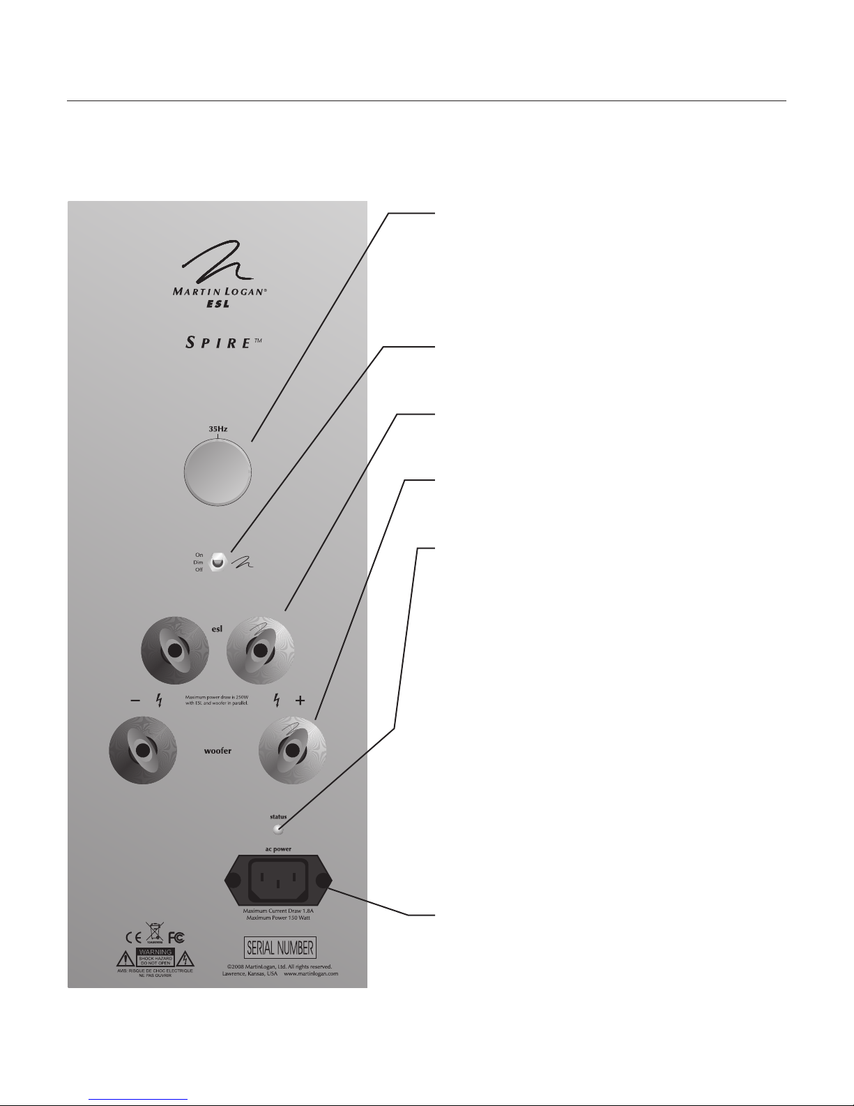
Controls and ConneCtIons
35Hz Level Knob
The 35Hz Level knob significantly adjusts the level
between 30 and 50Hz by ±10dB. This is an area where
peaks and dips of different amplitudes often manifest in
real environments. This setting is dependent on room size
and construction, system configuration and personal preference.
Light Switch
The light control switch allows the brightness of the illuminated MartinLogan logo to be dimmed or turned off.
ESL Signal Input
These binding posts provides a place to connect the signal
that drives the XStat™ ESL transducer.
Woofer Signal Input
These binding posts provides a place to connect the signal
that drives the PoweredForce™ woofer.
Status Light
The Spire is equipped with a multi-color LED to indicate
the current status of the PoweredForce™ woofer. The following list explains the meaning of the different colors:
No color: No power. The Spire is not plugged in.
Blue: Play mode. This indicates the Spire detects an audio
signal and has automatically switched into play mode.
Red: Standby mode. This indicates the Spire has detected no audio signal for approximately 15 minutes and has
automatically switched into standby mode.
Flashing Red: Initializing or Safe mode. This indicates that
the Spire is initializing. This also indicates if the Spire’s
temperature has exceeded nominal operating range. If the
Spire overheats, please allow the Spire to cool and reset
it by unplugging the unit and plugging it back in.
AC Power Connection
Because your MartinLogan Spire speakers use an internal power supply to energize their electrostatic cells and
PoweredForce™ woofer, they must be connected to an
AC power source.
Figure 1. Spire Controls and Connections
Controls and Connections 7
AC Power Connection
Because your Spire speakers use an internal power supply to energize their electrostatic cells and to power the
PoweredForce™ woofer, they must be connected to
an AC power source. For this reason they are provided
with the proper IEC standard power cords. These cords
should be firmly inserted into the AC power receptacles
on the rear connection panel of the speakers, then to any
convenient AC wall outlet. The Spire’s integrate a signal
sensing power supply which will switch off after 15 minutes of no music signal, and requires less than four seconds
to recharge the panels when a music signal is present.
Your Spire speakers are wired for the power service
supplied in the country of original consumer sale.
The A C power r atin g applicabl e to a parti cular unit is specified both on the packing carton and
on the serial number plate attached to the speaker.
If you remove your Spire speakers from the country
of original sale, be certain that the AC power supplied in
any subsequent location is suitable before connecting and
operating the speakers. Substantially impaired performance
or severe damage may occur to an Spire speaker if operation is attempted from an incorrect AC power source.
WARNING! The power cord should not be
installed, removed, or left detached from the
speaker while the other end is connected to an
AC power source.
Signal Connection
Use the best speaker cables you can. The length and type
of speaker cable used in your system will have an audible
effect. Under no circumstance should a wire of gauge
higher (thinner) than #16 be used. In general, the longer the length used, the greater the necessity of a lower
gauge, and the lower the gauge, the better the sound,
with diminishing returns setting in around #8 to #12.
A variety of cables are available whose
claim better performance than standard heavy gauge wire.
manufacturers
We have verified this in many cases, and the improvements
available are often more noticeable than the differences
between wires of different gauge. The effects of cables
may be masked if equipment is not of the highest quality.
Connections are done at the signal input section on the
rear electronics panel of the Spire. Use spade connectors
for optimum contact and ease of installation. Hand tighten the binding posts, but do not overtighten—do not use
a tool to tighten the binding posts.
Be consistent when connecting the speaker cables to the
signal input terminals. Take care to assign the same color
cable lead to the (+) terminal on both the left and right
channel speakers. If bass is nonexistent and you cannot
discern a tight, coherent image, you may need to reverse
the (+) and (–) leads on one speaker to bring the system
into proper polarity.
WARNING! Turn your amplifier off before
making or breaking any signal connections!
Break-In
When you first begin to play your Spire speakers, they
will sound a bit bass shy. This is due to the high quality,
long-life components used in our woofer. Our custom
made, butyl surround woofer requires approximately
72 hours of break-in at 90 dB (moderate listening levels)
before any critical listening. The break-in requirements
of the crossover components (and, to a lesser degree, the
stator) are equivalent.
Jumper Clips
In some countries federal law prohibits MartinLogan from
supplying jumper clips. If none are found installed under
your speakers binding posts, please refer to ‘Bi-Wire
Connection’ for connection instructions.
8 Controls and Connection

Single Wire Connection
Please take note of the jumper clips installed under the
binding posts. These clips attach the high and low frequency sections of the crossover together. Leaving these
in place, connect the (+) wire from your amplifier to
either red binding post and the (–) wire from your amplifier to either black binding post (see figure 2).
Bi-Wire Connection
Bi-wiring the Spire is not necessary. The Spire is provided with a bi-wiring option to allow consumers who
already own quality bi-wire cables to use their existing
cables. This connection method replaces the jumper clips
installed
speaker wire from your amplifier. This doubles the signal
carrying conductors from the amplifier to the speaker, thus
under the binding posts with individual runs of
direct-coupling each portion of the crossover to the amplifier.
First you must remove the jumper clips. Connect one set
of wires to the upper set of ESL binding posts. Next, connect a second set of wires to the lower woofer binding
posts. Finally, connect both sets of wires to the appropriate terminals on your amplifier. Please take care to
connect both (+) wires to the (+) amplifier terminals and
both (–) wires to the (–) amplifier terminals. This is also
known as a parallel connection (see figure 3).
Bi-Amplification
The Spire’s PoweredForce™ woofer is internally powered.
Because of this, we do not recommend either active or
passive bi-amplification.
Figure 2. Single-wire connection. One channel shown. Figure 3. Bi-wire connection. One channel shown.
Controls and Connection 9
 Loading...