

Page 1
tl<i?!t~~T
S
l_
L
user's
manual
Page 2
The
symbol, within an equilateral triangle,
intended
is
potentially
of
ence
product's enclosure
of electric shock.
risk
tute a
lightning
bolt flash
alert
to
"dangerous voltage" within the
that may be sufficient
with arrowhead
to
user
the
to
the
pres-
consti-
Connection
Installation.
Break
Installing
Installing
Installing
Moving
Frequently
. . . . . . . . . . . . . . . . . . . . . . . . . . . . 4
. . . . . . . . . . . . . . . . . . . . . . . . . . . . 4
..
....
In
Wall
A
On
Horizontal Stands .
the
Vertical Stand
the
Logo
the
Asked
Troubleshooting
Contacting
General
Warranty Information
Serial Number
Service . .
Specifications
Dimensional
With
With
With
Customer
Information
.............
...
. . . . . . . . . . . . . . . . . . . . . . . . . . 8
Drawings
Bracket .
Wall
Horizontal Stand . .
Vertical Stand
....
..
....
.....
Badge
......
Questions
........
..
..
. .
..
. .
..
....
..
...........
.....
. . .
. . . . . . . . . . . . . . . 6
4
. 4
..
5
...
.
. . 5
. 6
. . . . . . . . . . . . . . . . . . . . . . . . 6
Service
.....................
.
....
.
..
.....
.
.................
.
.........
....
.....
. . .
..
. . . . . . . . . . . . .
.. ..
....
........
.
...
...
..
...
.
..
.
........
..
...
.
..
7
7
. . 7
..
7
7
...
.
9
9
..
9
0
. 1
The exclamation point within an equi-
in
2005,
arranged
you.
the
the
WEEE
we
intended to alert
triangle
_lateral
to the presence
&
ating and maintenance (servicing) instructions
literature accompanying
~
A
uAuo2oos
would like
regulated materials which upon disposal, according to
WEEE
the
processing.
with our distributors
collect
user
accordance with
In
(Waste
directive
directive, require
and
Electrical
effective August
to notify you that this product may contain martinlogan.com.
reason Martin Logan
this
For
European Union member nations
in
this
recycle
is
important oper-
of
appliance.
the
European Union
the
and Electronic Equipment) from whom you purchased
3,
l
and recycling
special
product at no cost
reuse
has
to
Serial Number:
--------------------------
Record your serial number here for easy reference.
information when filling out your
binding
only
When
.
through
this
posts
distributor
product
this
disposing
the
serial number
The
and
please
this
distributor
the
itself falls
of
encourage you
we
normal
the
on
contact
product,
packaging
channels.
product carton.
email
locator
under
will need
You
warranty registration.
the
near
find your local
To
martinlogan.com or visit
note,
Please
directive
shipping materials
related
to
items
these
is
the
at
the
and
to
located
dealer
info@
www.
WEEE
other
recycle
2
CE:
Page 3
x1
x2
x3
3
Page 4
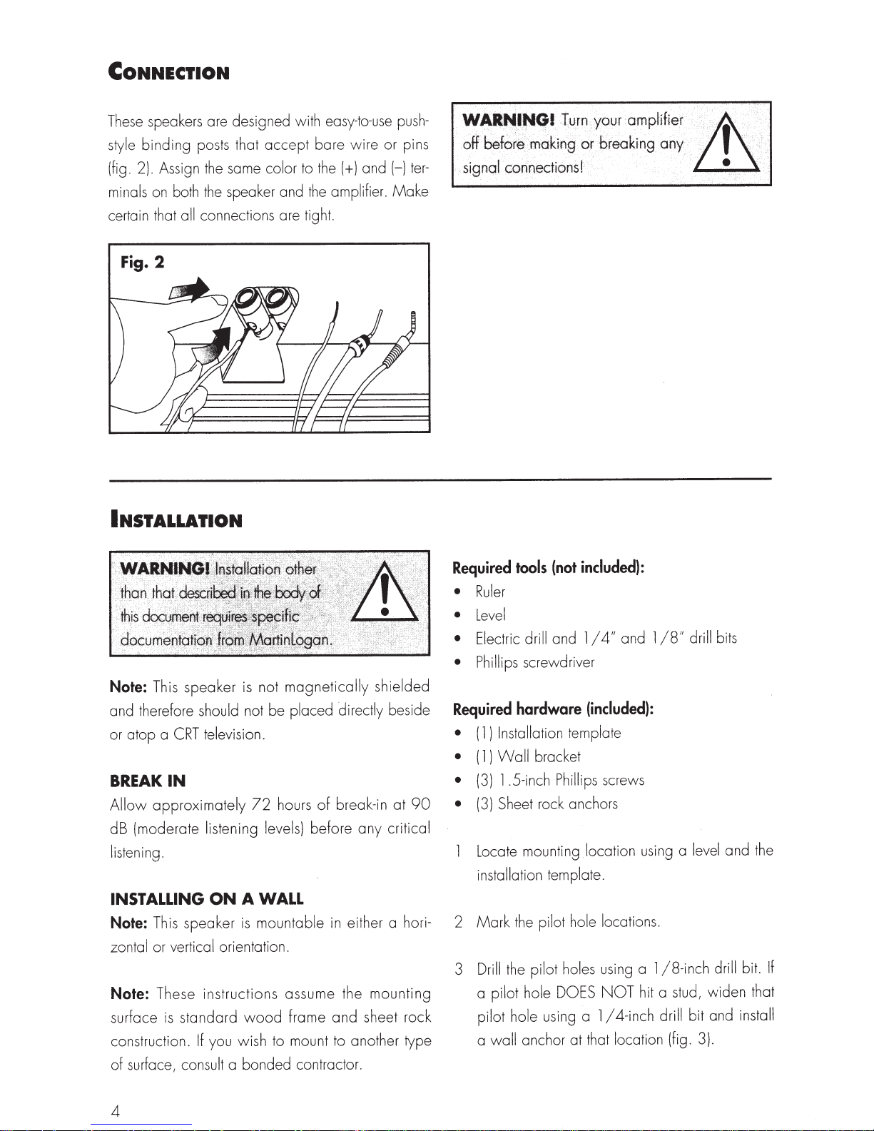
CONNECTION
speakers are designed with easy-to-use
These
binding
style
(fig. 2). Assign
minals on both
certain that
Fig.
all
2
posts that
the
the
connections are tight.
accept
same color
speaker and
to
INSTALLATION
bare
the
amplifier .
the
wire
(+)and
push-
or pins
ter-
(-)
Make
"'~'"!
f0(~
.
be
elf
connections! ... ·
signal
.
~t}Fnx¥6ur
breaking
i
11loki~g
:
or
arnpkfier
any
zrs
··
··
}
..
·< ..
•·.f
··.·
..
•
....
magnetically
not
Note:
and therefore should not be placed directly beside
or atop a
BREAK
Allow
dB (moderate listening
Note:
zontal
Note:
This speaker
CRT
IN
approximately
listening.
INSTALLING
This speaker
or vertical orientation.
These instructions assume the
standard
surface
construction.
of surface, consult a bonded contractor.
is
If
is
television.
of
hours
72
levels)
A WALL
ON
mountable
is
wood
you wish to mount to another type
before
frame
in
and
shielded
90
break-in
either a hori- 2
at
critical
any
mounting
sheet rock
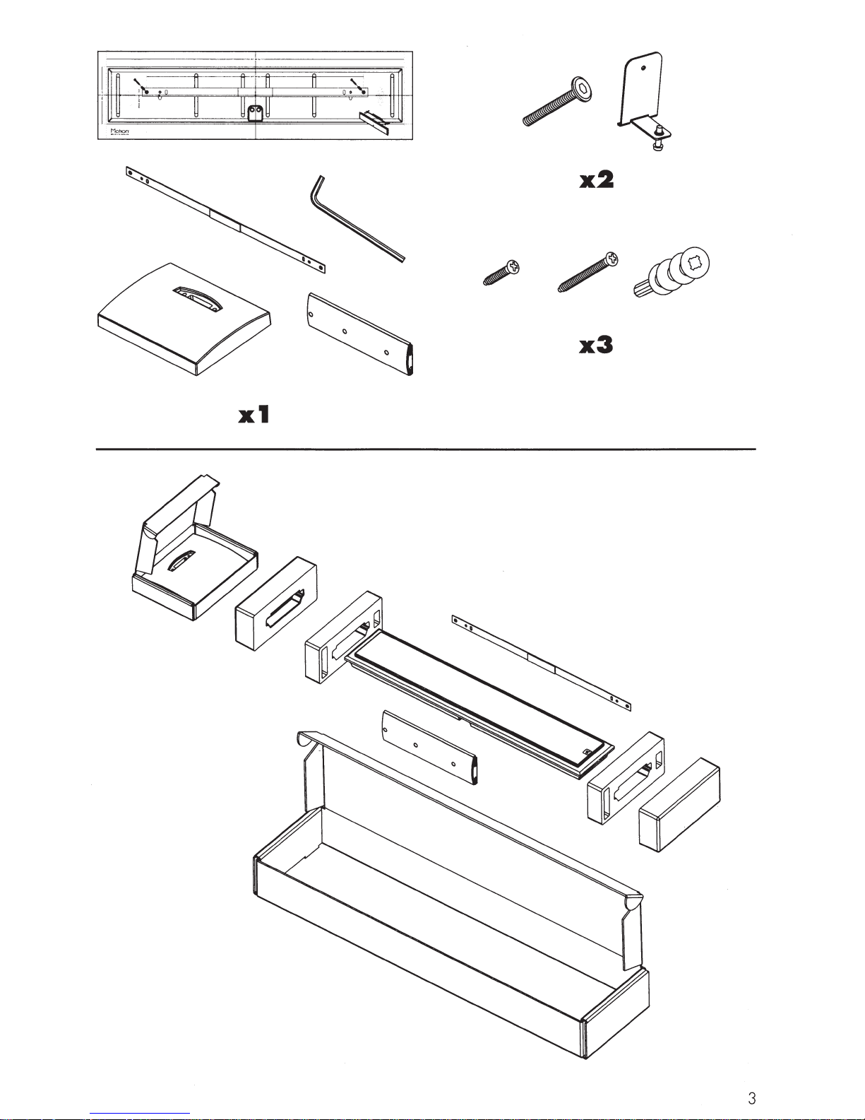
Required
•
•
•
• Phillips
Required
•
•
•
•
3 Drill
tools
Ruler
Level
Electric
screwdriver
hardware
Installation
1)
(
Wall
1 )
(
.5-inch
1
(3)
Sheet rock anchors
(3)
Locate mounting
installation
the
Mark
the
pilot hole DOES
a
pilot hole
anchor at that location (fig. 3).
wall
a
(not
and
drill
template
bracket
Phillips
template.
pilot hole
pilot holes
using a
included):
and
4"
I
1
(included):
screws
location
l
using a level
locations.
using a
hit a stud,
NOT
4-inch
I
18"
1
18-inch
1
drill
drill bits
and the
drill
widen
and
bit
bit.
that
install
If
4
Page 5
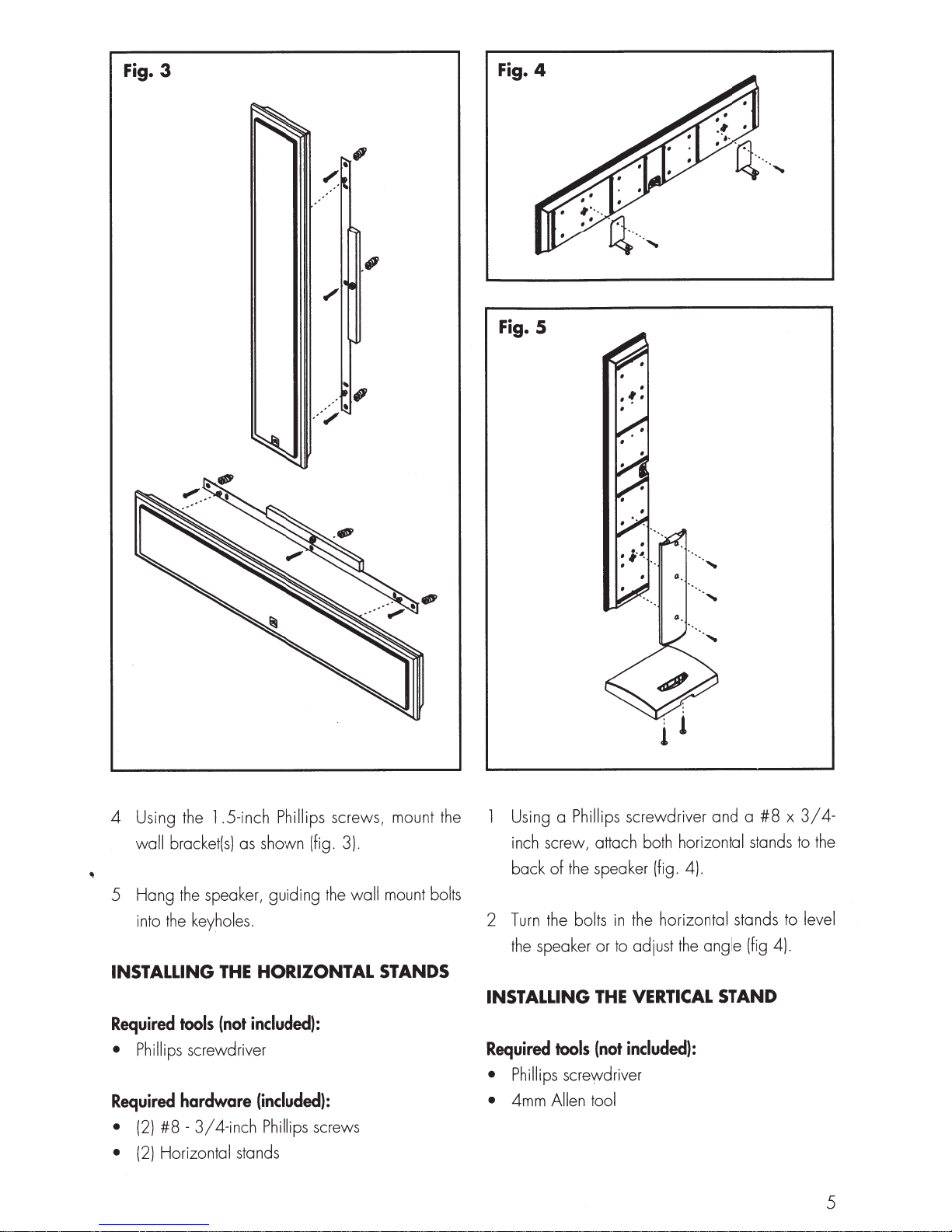
Fig. 3
.·
.··
""
...
'
.
·'
4
Fig.
Fig. 5
.5-inch Phillips
4 Using the
wall
5 Hang the speaker, guiding
into the
INSTALLING
Required
• Phillips
Required
#8
(2)
•
Horizontal
(2)
•
l
bracket(s) as shown (fig. 3).
keyholes.
HORIZONTAL
THE
included):
(not
tools
screwdriver
4-inch
stands
(included):
Phillips screws
hardware
3/
-
screws, mount the
wall mount
the
bolts
STANDS
Using a
inch screw, attach both
back
Turn
2
the
Phillips
the speaker (fig. 4).
of
bolts
the
speaker or to adjust
INSTALLING
4mm
tools
Allen tool
Required
• Phillips screyvdriver
•
screwdriver and a
the
in
VERTICAL
THE
included):
(not
horizontal
horizontal
angle
the
STAND
x
#8
stands to the
stands to
(fig 4).
3/4-
level
5
Page 6

Required
•
•
•
•
hardware
3/
-
#8
(3)
50mm Allen
(2)
Vertical stand pillar
( l)
base
Stand
l )
(
Using the Allen tool
screws, attach the vertical stand
stand base (fig. 5) .
(included):
4-inch Phillips
screws
and
screws
two
50mm
pillar
Allen
to the
2 Using a Phillips screwdriver
4-inch screws, attach the vertical stand to
3/
speaker (fig. 5).
back of
the
MOVING
logo
The
your fingers,
reattach
it
the
LOGO
THE
badge
at
is
it
pull
desired position.
the
BADGE
attached magnetically. Using
the
from
away
#8
three
and
grille cover and
x
FREQUENTLY
I clean
How
or a soft
Do
close
Could
do
a dust free
Use
not
proximity
tronics
cloth
to
brush
any
spray
to
you suggest a
cables ideal
and
AsKED
speakers?
my
(such
remove dust
of
kind
drivers.
the
QuESTIONs
a micro fiber
as
your speakers.
from
cleaning
list
agent
suitable elec-
of
MartinLogan
for
on
cloth)
in
or
speakers?
above
the
and
all
best
use electronics
have no favorites
We
cables quite interchangeably.
listening to a number
else-trust
source for information when purchasing additional
audio equipment.
your ears. Dealers are always
and
We
brands-and
of
would suggest
there
Is
between
sion in
These speakers are not shielded and should
Yes.
be kept at least 2 feet
Will
performance
or
recommend against placing any loudspeaker
We
direct sunlight. Ultraviolet
in
can cause deterioration of cabinet, speaker cones,
Small
etc.
. Filtering
lem
reduce
likely
my
A/V
my
exposure
exposures
of
negative effects.
the
to
speakers
system?
from
away
sunlight
to
speakers?
my
of
(UV)
will
UV
to
rays through glass
UV
televi-
the
and
television.
CRT
a
aHect the
the
from
rays
not cause a prob-
greatly
will
life
sun
interaction
any
be
TROUBLESHOOTING
Output
No
• Check
on
• Check speaker wires and connections.
• Check all
If
•
please contact your dealer or Martinlogan
tomer service.
6
that all system components are turned
and source material
interconnecting cables.
unable
are
you
is
to resolve
playing.
your
problem,
cus-
Page 7

CoNTACTING
CusTOMER
SERVICE
Martinlogan
Monday-Friday
(central
emailing
time) by
GENERAL
WARRANTY
Your
speakers are
Limited
the
Limited
Limited 5
complete
to
your convenience
warranty registration at www.martinlogan.com.
Martinlogan
claims unless
Registration card
Certificate
you cannot be assured
units.
rized Martinlogan
90
option, at no
5
Martinlogan
If
this
customer
between
calling
service@martinlogan.com.
service
the
hours of
(785)
is
7
49-0133
available
8am-5pm
or by
INFORMATION
INFORMATION
provided
Day
Warranty
additional
Year
Warranty coverage.
Year
Warranty
and
return
the
within
may not honor
we
of Registration with your new speakers
is
the
30
Martinlogan
have a
on
file!
case,
please
dealer.
with an automatic
coverage.
charge,
coverage you need to
Certificate
days
of
also offers
warranty
completed
If
you
did
of
having received new
contact your autho-
You
to
receive a
To
obtain
of Registration
purchase.
online
service
Warranty
not receive a
have
the
For
SERVICE
Should
country other
purchased,
1
given country
only
try
2
vicing
it was
seek to have repairs performed by the nearest
Martinlogan
tor's
(parts,
owner of
you
use
your
Martinlogan
than
the
one
in
which
we
ask
that
you
note
The
appointed Martinlogan distributor for any
is
on
units
distributed by or
in
accordance with
Should
local
a
Martinlogan
in
a country other than
originally
distributor, subject
servicing
labor,
transportation)
the
Martinlogan product.
responsible
purchased, the end user may
policies,
for warranty servicing
through
its
applicable
product require ser-
but
must
product
it
was
the
following:
it
in
warranty.
the
one
to
that distribu-
all
cost of repairs
be borne by
in
originally
that
coun-
in
which
the
a
SERIAL
The
er,
number may
NUMBER
serial
directly
number
beneath
also
is
located
the
binding posts:
be found
on
on
back of
the
product carton.
the
The
speak-
serial
3
If,
after
owning your speaker
relocate
you
transferable. Contact
to
a country other than
purchased your speaker, your warranty may be
Martinlogan
for
the
six
for
months,
one
details.
in
you
which
7
Page 8

5PECIF~CAIIONS*
Frequency
Response
. . . . . . . . . . . . . . . . . . . . .
MARTINLOGAN
100-25,000
MOTION
Hz±
3 dB
SLM
XL
D1spers1on
...
ns1tiv1ty'.
Se
Impedance
Crossover
High
Low
Cabinet
. . . . . . . . . . . . . . . . . . . . . . . . . . . .
. . . . . . . . . . . . . . . . . . . . . . . . . . . .
.
Frequency.
Frequency
Frequency
. . . . . . . . . . . . . . . . . . . . . . . . . . . . . .
..........................
. . . . . . . . . . . . . . . . . . . .
Driver
Drivers
. . . . . . . . . . . . . . . . . . .
. . . . . . . . . . . . . . . . . . .
dB@
94
4 Ohms.
.
amplifiers.
00
3, 1
1" x 1
Transducer with
diaphragm.
4"
Two
paper cone
led
Sea
volts/
2.83
Compatible with
(2-way design}
Hz
.6cm x 3 .6cm} Folded
(2
.4"
5.25"
passive
paper cone.
radiators.
( 1 0.2cm}
meter
1.75"
x
4,
6 or 8
Four
Ohm
Motion
( 13.3cm x 4.4cm}
( 1
4"
rated
0.2cm}
Components.
Recommended
Binding
. . . . . . . . . . . . . . . . . . . . . . . . . .
. . . . . . . . . . . .
Post
Amplifier
Inputs
Power.
. . . . . . . . . . . . . . . . . . . . . .
Weight.. . . . . . . . . . . . . . . . . . . . . . . . . . . . . .
Dimensions
with
wall
bracket
(HxWxD).......
Custom
capacitors
capacitors
rent
20-140
Push
9
34.1"
air
protection.
style
lbs. (4. 1
6.4"
x
coil
core
and
series
in
parallel. Overall
in
watts
kg)
.89"
x 1
inductors. Polyester
electrolytic
DF
low
system
(86.7cm x 16.2cm x 4.8cm}
film
thermal/
cur-
subject
*Specifications
8
are
to
change
without
notice.
Page 9

DIMENSIONAL
MARTINLOGAN
MOTION
DRAWINGS
SLM
XL:
WITH
WALL
BRACKET
•
@
•
@
• •
@
•
[j]
• •
@
•
@
•
@
•
•
•
•
•
•
•
0 0
0 0
c
0
0
0
0 0
0
1.89" (4.8
DIMENSIONAL
MARTINLOGAN
,
...
em)~
DRAWINGS
MOTION
SLM
XL:
34. 1" (86.7
I
14-~
------.!1016.4"
WITH
HORIZONTAL
em)
(16.2
STAND
em)
3.8"
(9.6
em)
\~--~------~•~mm~•----~~----/
w
·w
9
Page 10

DIMENSIONAL
MARTINLOGAN
MOTION
E
u
DRAWINGS
SLM
XL:
WITH
VERTICAL
STAND
0 0
0
<>
0
0
.
0
0
0
0
0
0
[
I
~
I I
0 0
•
~
D
•
•
..------.
D
=
-----==-
I
~
=
I
I
-----==-
Lawrence,
P/N:
9500090
Kansas,
USA
MARTIN
tel
785.749.0133
©20
1 3 MartinLogan
LOGAN®
fax
785.749.5320
Ltd.
All
rights
reserved.
www.martinlogan.com
Rev.
#0606
1 3
Page 11

~
--------
------------------
----------------
------
------
--
------
--------------
----
----
----------
----
------
----------------
----
------
--34.1"(86.7cm)
----
------
----
------
--------
--------
----------
--------------
------
------
----
--------
--
----
--------
--
------------
----------------
--
--
~
~
I
-----
--
~
----
--
r-
------
---------
3 '
-
I
I
I
I
Motion®
MARTIN
LOGAN
'
_,--,
(
'-
......
\
J
'-·-/
.
'
'
I
~----·
'
..
'
'
i'-,
/'~
t " '
, I
f
I
'
'
"'
'
'
--
~
-----
--
----
--
-
-----
--
-------------- --
PN
:
950009
1
i
I
Page 12

i+---------
- - 6.4"
(16.2cm) --------'---
- - - ----.
1-----
- - -
---
- -
-----+---
- - - - -
------
- +
------·--·--·--
----·--···-·-·------
e
~
.0
·---
---------~
-------------
--
(
]]
'
'
'
'
i
CD
I
I
I
- ..
..
···
········ ...........
.
--
--
~
'
'
'
'
(
ll
I
I
I
I
I
I
@)
'I
I
I
I
I
I
I
I
(g)
I
©
--
~
I
I
I
I
I
I
I
I
I
I
I
I
I
I
I
Motion
e
c:·
I M
XL
MAR
T I N
LOGAN
, _) L I
[[
)
_ .. ··
g
,
[[
)
..
,
__
..
· '
...
,.
----·--·-----~
---
PN. 950009
1
Page 13

MARTIN
LOGAN
®
BUSINESS
REPLY
MAIL
FIRST-CLASS
MAIL
PERMIT
NO.
66
LAWRENCE,
KS
POSTAGE
WILL
BE
PAID
BY
ADDRESSEE
MARTIN LOGAN
2101
DELAWARE
ST
LAWRENCE,
KS
66046-9702
USA
1.11
•••
11
••
11
••••
1
••
1.11
••
1.1
••
1
•••
111
•••••
1.111
•••
1
NO
POSTAGE
NECESSARY
IF
MAILED
IN
THE
UNITED
STATES
Page 14

I
Important!
To receive a Limited Five Year Warranty (Three Year
Warranty
for
subwoofers), free
of
charge, you must
return this registration card
within
30 days from
date
of
delivery. For
your
convenience
Martinlogan
offers full .warranty details and online warranty
registration at
www.martinlogan.com.
Important:
Please
retain
your
receipt. A
copy
of
your
receipt
will
be required should
your
speaker require servicing in the future.
Contact
Information
Name
-------------------------------------
Address
-------------------------------------
City
---------------------------------------
State
-----------------
Zip
______________
_
Phone
-------------------------------------
E-mail
-------------------------------------
0 Check here
if
you
would
like
to
receive occasional email
updates about news and opportunities regarding Martin logan.
Register online at www.Martinlogan.com!
Speaker
Information
Model(s)
------------------------------------
Serial #(s)
-----------------------------------
Date
of
Purchase
------------------------------
Date
of
Delivery
____________________________
_
Retail Store
Name
-----------------------------
Salesperson
1
S Name
__________________________
_
How
did
you initially
learn
about
Martinlogan
ichouc,c ont'l?
0 Internet 0
Sales
associate 0 Friend
or
family
member
0
Audio
magazine (please specify):
_______
_
0
Other
magazine (please specify):
_______
_
0
Other
(please specify):
______________________
_
Rev.060909
 Loading...