

Page 1
TM
NEOLITH
USER’S MANUAL
Page 2

Page 3

tm
Page 4

Page 5

user’s manual | manuel de l’utilisateur
tm
®
Page 6

This high performance Neolith hybrid electrostatic
loudspeaker was hand-crafted exclusively for:
__________________________________________________________
Serial Numbers: Record your serial numbers here for easy reference.
You will need this information when filling out your warranty registration.
Neolith’s serial number is located near the bottom of the backplate and
on the shipping container. Each individual unit has a unique serial number.
Numéros de série : Veuillez noter les numéros de série afin de pouvoir les consulter facilement. Vous aurez besoin de ces renseignements
lorsque vous remplirez l’inscription à la garantie. Le numéro de série Neolith est situé près du bas de la plaque arrière et sur le carton
d’emballage. Chaque appareil possède un numéro de série unique.
___________________ / ___________________
©2014 MartinLogan Ltd. All rights reserved. Tous droits réservés.
Page 7

Thank you—to you the MartinLogan owner,
for loving what we do,
and making it possible for us to do what we love.
________________________________________
Merci à vous, propriétaire d’un produit MartinLogan,
d’aimer ce que nous faisons,
et de faire en sorte que nous puissions faire ce que nous aimons.
MartinLogan’s Neolith Team
__________________________________________________________
Greg Dunham, Director of Engineering
__________________________________________________________
Devin Zell, Product Manager
__________________________________________________________
Eric Urban, Project Manager
__________________________________________________________
Pat Shoup, Engineering Technician
__________________________________________________________
Joe Vojtko, Chief Audio Technologist
__________________________________________________________
Joe McCracken, Senior Loudspeaker Engineer
__________________________________________________________
Blair Sutton, Lead Mechanical Designer
__________________________________________________________
Brian Kirby, Engineering Technician
Page 8

Page 9

INTRODUCTION | INTRODUCTION
Congratulations! You have invested in one of the world’s
premier loudspeaker systems.
The MartinLogan Neolith represents an advanced combination
of sonic technologies establishing an unprecedented direction for audiophile design. The result of years of research, the
new Neolith hybrid electrostatic loudspeaker features XStat
technology, powerful woofers, and meticulous crossover engineering establishing new standards for efficiency, dynamics
and precision in a floorstanding loudspeaker.
The Neolith’s CLS XStat transducer builds upon the legacy of
MartinLogan’s electrostatic heritage with the incorporation
of advanced vacuum bonding and MicroPerf stat panels. The
electrical interface technology, developed by MartinLogan’s
CLX™ engineering team, extends effortless dynamics and
purity, resulting in high sonic standards of efficiency and precision. Through rigorous testing the curvilinear electrostatic
panel has proven itself to be one of the most durable and reliable transducers available today. Fabricated from a custom
tool punched high-grade steel, the patented panel is then
coated with a special polymer that is applied via a proprietary
electrostatic bonding process. This panel assembly houses a
membrane just 0.0005 of an inch thick.
Félicitations! Vous avez acheté l’un des meilleurs systèmes de
haut-parleur au monde.
Le MartinLogan Neolith est une combinaison perfectionnée de technologies sonores qui établit un jalon inégalé pour les audiophiles. Résultat de
nombreuses années de recherche, le nouveau haut-parleur électrostatique
Neolith est doté de la technologie XStat, qui permet de diminuer de beaucoup la taille du boîtier, tout établissant de nouvelles normes en matière
d’efficacité, de dynamique et de précision des haut-parleurs au sol.
Le nouveau transducteur CLS XStat du Neolith puise dan l’héritage
électrostatique de MartinLogan en incorporant le collage sous vide
et des panneaux statiques MicroPerf perfectionnés, ce qui offre une
efficacité et une précision encore plus élevées. La technologie de
l’interface électrique élaborée par l’équipe d’ingénierie CLX™ de
MartinLogan permet d’accroître la dynamique et la pureté sans effort,
ce qui permet d’obtenir des normes sonores d’efficacité et de précision encore plus élevées. Grâce à des essais rigoureux, le panneau
électrostatique curvilinéaire est l’un des transducteurs les plus durables
et fiables actuellement sur le marché. Fabriqué à partir d’un acier de
calibre élevé étampé par un outil sur mesure, le panneau breveté est
ensuite recouvert d’un polymère spécial qui est appliqué selon un processus de collage électrostatique exclusif. Ce panneau est doté d’une
membrane d’une épaisseur de seulement 0,0005 pouce.
Featuring an advanced crossover topology, each Neolith
crossover uses precision audiophile-grade polypropylene
capacitors, toroidal transformers, and high-purity air-core and
iron-core coils. This advanced crossover topology flawlessly
preserves microscopic subtleties while effortlessly handling the
broadest range of dynamics contained within even the most
demanding sonic source.
The materials in your new Neolith speakers are of the highest
quality and will provide years of enduring enjoyment and
deepening respect. The cabinetry is constructed from the highest quality phenolic material for acoustical integrity.
This User’s Manual explains in detail the operation of your
Neolith speakers and the philosophy applied to their design.
A clear understanding of your speakers will insure that you
obtain maximum performance and pleasure from this most
exacting transducer. It has been designed and constructed to
give you years of trouble-free listening enjoyment.
Présentant une topologie de répartiteur perfectionnée dérivée du
haut-parleur CLX, chaque répartiteur Neolith utilise des condensateurs en polypropylène de haute qualité et des bobines à noyau d’air
de grande pureté. Cette topologie de répartiteur perfectionnée permet
de préserver les subtilités microscopiques tout en traitant sans effort la
plage la plus élevée de dynamiques qu’elles contiennent, même pour
les sources sonores les plus exigeantes.
Les matériaux de vos nouvelles enceintes Neolith sont de la plus haute
qualité et vous offriront de nombreuses années de plaisir. Le boîtier
est fait du matériel composite de la plus haute qualité pour préserver
l’intégrité acoustique.
Les autres sections du manuel de l’utilisateur expliquent en détail le
fonctionnement des enceintes Neolith et la philosophie sous-jacente à
leur conception. En ayant une compréhension claire de vos enceintes,
vous obtiendrez le rendement maximal de ce transducteur le plus précis qui soit et en profiterez pleinement. Il a été conçu et fabriqué pour
vous donner des années d’écoute exceptionnelle et sans tracas.
Page 10

Page 11

CONTENTS | TABLE DES MATIÈRES
Controls and Connections ................................1
AC Power Connection....................................1
Signal Connection .......................................1
Break-In...............................................1
Jumpers . . . . . . . . . . . . . . . . . . . . . . . . . . . . . . . . . . . . . . . . . . . . . . . 2
Single Wire Connection ..................................2
Bi-Wire Connection .....................................2
Passive Bi-Amplification ..................................2
Active Bi-Amplification ...................................3
Top Panel Controls ......................................4
Low Bass Output Jumpers.................................5
Listening Distance Jumpers ................................5
Placement..............................................7
Listening Position........................................7
The Wall Behind the Listener ..............................7
The Wall Behind the Speakers .............................7
The Side Walls .........................................7
Experimentation ........................................7
Final Placement ........................................9
The Extra “Tweak” ......................................9
Enjoy Yourself ..........................................9
Room Acoustics ........................................13
Your Room ...........................................13
Terminology ..........................................13
Rules of Thumb .......................................13
Dipolar Speakers and Your Room..........................14
Solid Footing ..........................................14
Dispersion Interactions..................................17
Controlled Horizontal Dispersion ..........................17
Controlled Vertical Dispersion ............................17
Three Major Types of Dispersion ..........................17
Home Theater..........................................19
Electrostatic Advantages .................................21
Full Range Operation ...................................22
MartinLogan Exclusives..................................25
XStat™ Transducer .....................................25
CLS™ (Curvilinear Line Source) ...........................25
Generation 2 Diaphragm ................................25
MicroPerf Stator .......................................25
Vacuum Bonding.......................................25
Electrostatic Loudspeaker History .........................27
Frequently Asked Questions..............................31
Troubleshooting........................................35
Specifications ..........................................37
General Information ....................................39
Warranty and Registration................................39
Serial Number .........................................39
Service ..............................................39
Glossary of Audio Terms .................................41
Raccords et commandes .................................47
Raccord de l’alimentation CA ............................47
Raccord du signal ......................................47
Rodage ..............................................47
Pinces de démarrage....................................48
Raccord à un fil . . . . . . . . . . . . . . . . . . . . . . . . . . . . . . . . . . . . . . . . 48
Raccord à deux fils .....................................48
Bi-amplification passive..................................48
Bi-amplification active ..................................49
Commandes du panneau supérieur ........................50
Bretelles de sortie de basses profondes .....................51
Écouter les bretelles de distance ...........................51
Positionnement ........................................53
Position d’écoute.......................................53
Le mur derrière l’auditeur ...............................53
Le mur derrière les enceintes .............................53
Les murs latéraux.......................................53
Expérimentation .......................................53
Positionnement final . . . . . . . . . . . . . . . . . . . . . . . . . . . . . . . . . . . . 55
Mise au point supplémentaire.............................55
Profitez du produit .....................................55
Acoustique de la pièce ..................................59
La pièce..............................................59
Terminologie ..........................................59
Règles pratiques .......................................59
Enceintes dipolaires et votre pièce .........................60
Base solide............................................60
Interactions de la dispersion .............................63
Dispersion horizontale contrôlée ..........................63
Dispersion horizontale contrôlée ..........................63
Trois principaux types de dispersion........................63
Cinéma maison ........................................65
Avantages électrostatiques ...............................67
Plage complète de fonctionnement ........................68
Exclusivités MartinLogan.................................71
Transducteur XStat™....................................71
CLS™ (Source linéaire curvilinéaire) ..........................71
Diaphragme Generation 2 ...............................71
Stator MicroPerf .......................................71
Collage sous vide.......................................71
Historique des haut-parleurs électrostatiques...............73
Foire aux questions .....................................77
Dépannage ............................................81
Spécifications ..........................................83
Renseignements généraux ...............................85
Garantie et enregistrement ...............................85
Numéro de série .......................................85
Service ..............................................85
Glossaire des termes audio...............................87
Page 12

12
Page 13
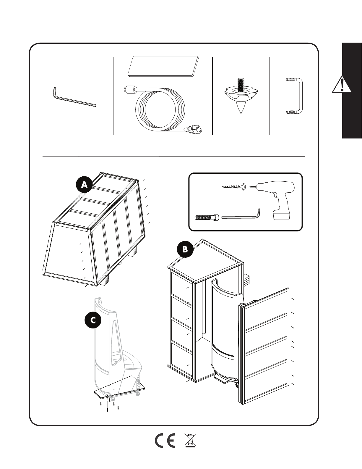
x6
x5
5/16”
x2x1 x8 x8
x27
x6
x5
5/16”
x8
x7
Page 14
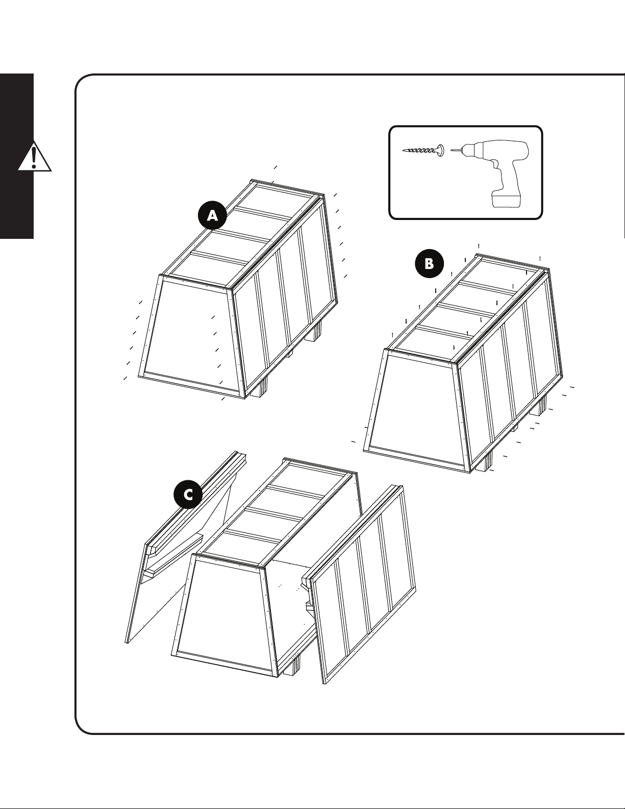
x6
x74
x6
x6
x7
x7
x6
x8
x8
14
Page 15
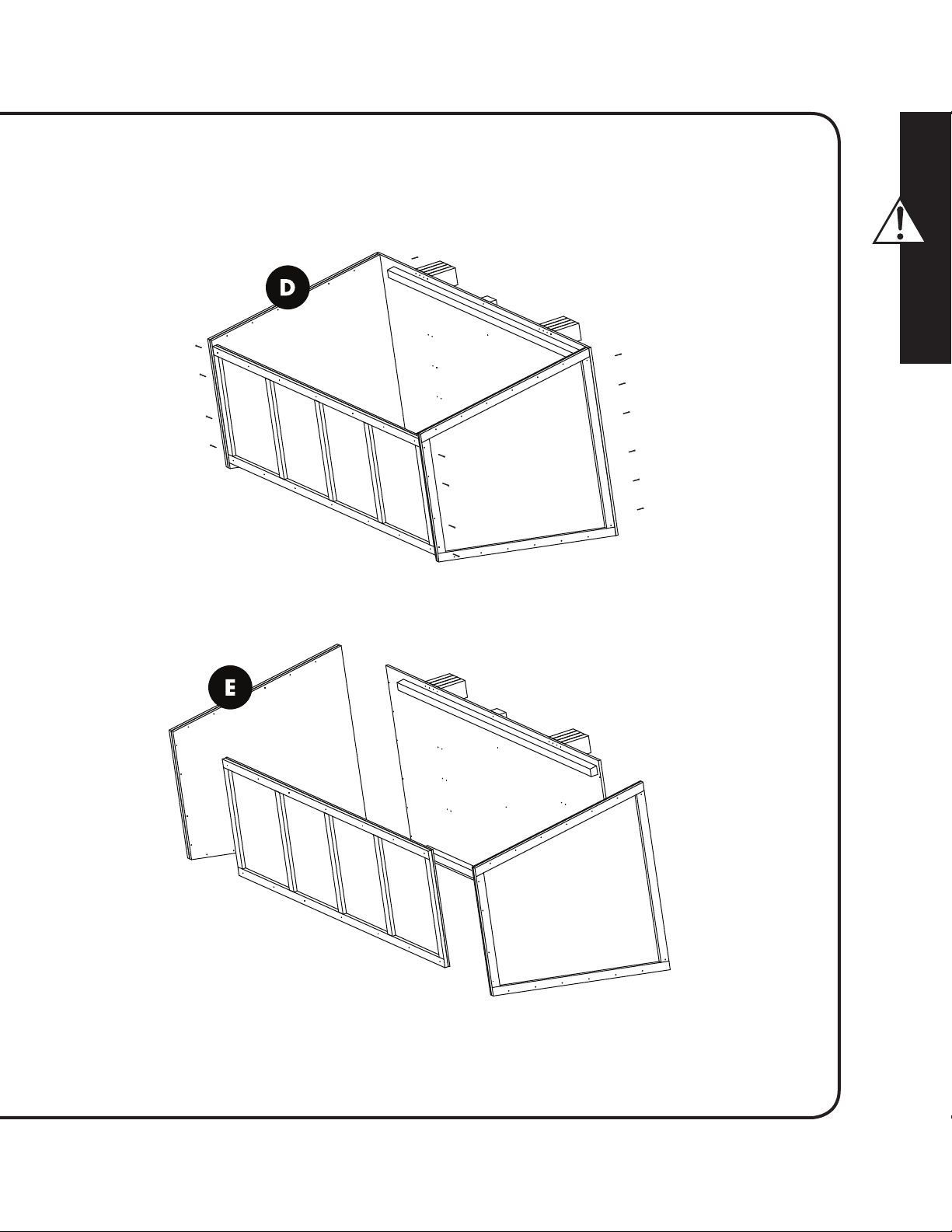
x6
x4
x6
x4
Page 16
1 Read these instructions.
2 Keep these instructions.
3 Heed all warnings.
4 Follow all instructions.
5 Do not use this apparatus near water.
6 Clean only with dry cloth.
7 Do not block any ventilation openings. Install in accor-
dance with the manufacturer’s instructions.
8 Do not install near any heat sources such as radiators,
heat registers, stoves, or other apparatus (including amplifiers) that produce heat.
9 Do not defeat the safety purpose of the polarized or
grounding-type plug. A polarized plug has two blades
with one wider than the other. A grounding type plug
has two blades and a third grounding prong. The wide
blade or the third prong are provided for your safety. If
the provided plug does not fit into your outlet, consult an
electrician for replacement of the obsolete outlet.
10 Protect the power cord from being walked on or pinched
particularly at plugs, convenience receptacles, and the
point where they exit the apparatus.
11 Only use attachments/accessories specified by the manu-
facturer.
12 Use only with the stand, tripod, bracket, or
table specified by the manufacturer, or sold
with the apparatus.
13 Unplug this apparatus during lightning storms
or when unused for long periods of time.
14 Refer all servicing to qualified service personnel. Servicing
is required when the apparatus has been damaged in any
way, such as power-cord or plug is damaged, liquid has
been spilled or objects have fallen into the apparatus, the
apparatus has been exposed to rain or moisture, does not
operate normally, or has been dropped.
15 The mains plug of the power supply cord shall remain
readily operable.
16 To completely disconnect this equipment from the mains,
disconnect the power supply cord plug from the receptacle.
17 WARNING! To reduce the risk of fire or electric shock,
this apparatus should not be exposed to rain or moisture
and objects filed with liquids, such as vases, should not be
placed on this apparatus.
CAUTION!
• To reduce risk of electric shock, do no remove cover
(or back).
• No user serviceable parts inside.
• Refer servicing to qualified service personnel.
Service Information
For service this product should be returned to your authorized distributor. In the US, please visit www.martinlogan.com for contact
information. Outside the US, please use the distributor locator at
www.martinlogan.com.
NOTE: This equipment has been tested and found to comply with
the limits for a Class B digital device, pursuant to part 15 of the FCC
Rules. These limits are designed to provide reasonable protection
against harmful interference in a residential installation. This equipment generates uses and can radiate radio frequency energy and,
if not installed and used in accordance with the instructions, may
cause harmful interference to radio communications. However,
there is no guarantee that interference will not occur in a particular installation. If this equipment does cause harmful interference to
radio or television reception, which can be determined by turning
the equipment off and on, the user is encouraged to try to correct
the interference by one or more of the following measures:
— Reorient or relocate the receiving antenna.
— Increase the separation between the equipment and receiver.
— Connect the equipment into an outlet on a circuit different from
that to which the receiver is connected.
— Consult the dealer or an experienced radio/TV technician for
help.
REMARQUE : cet équipement a été testé et jugé conforme aux limites d’un appareil numérique de Classe B, en vertu de la Section 15
du règlement de la FCC. Ces limites sont conçues pour offrir une
protection jugée raisonnable contre l’interférence nuisible dans une
installation résidentielle. Cet équipement génère des utilisations et
peut émettre une énergie radiofréquence et, s’il n’est pas installé et
utilisé conformément aux instructions, peut causer une interférence
nuisible aux radiocommunications. Toutefois, il n‘existe aucune
garantie qu’une interférence ne se produira pas dans une installation
particulière. Si cet équipement cause une interférence nuisible à la
réception radiophonique ou télévisuelle, qu’on peut déterminer en
ouvrant et en fermant l’équipement, l’utilisateur est invité à essayer
de corriger l’interférence à l’aide d’une des mesures suivantes :
— Réorienter l’antenne de réception ou la changer de place.
— Augmenter la distance entre l’équipement et le récepteur.
— Raccorder l’équipement à une prise située sur un autre circuit
que celui sur lequel le récepteur est raccordé.
— Consulter le revendeur ou un technicien radio/TV compétent
pour obtenir de l’aide.
Page 17
In accordance with the European Union WEEE (Waste
Electrical and Electronic Equipment) directive effective
August 13, 2005, we would like to notify you that this
product may contain regulated materials which upon
disposal, according to the WEEE directive, require special reuse and
recycling processing.
En vertu de la directive WEEE de l’Union européenne (directive sur les déchets électriques et
électroniques) entrée en vigueur le 13 août 2005,
nous vous avisons que ce produit pourrait contenir
des matériaux réglementés dont l’élimination doit faire l’objet de
procédures de réutilisation et de recyclage particulières.
For this reason MartinLogan has arranged with our distributors in
European Union member nations to collect and recycle this product
at no cost to you. To find your local distributor please contact the
dealer from whom you purchased this product, email info@martinlogan.com or visit the distributor locator at www.martinlogan.com.
Please note, only this product itself falls under the WEEE directive.
When disposing of packaging and other related shipping materials we
encourage you to recycle these items through the normal channels.
The exclamation point within an equilateral triangle is
intended to alert the user to the presence of important
operating and maintenance (servicing) instructions in
the literature accompanying the appliance.
The lightning bolt flash with arrowhead symbol, within
an equilateral triangle, is intended to alert the user to
the presence of uninsulated “dangerous voltage” within the product’s enclosure that may be of sufficient
magnitude to constitute a risk of electric shock.
WARNING! Do not use your Neolith loudspeakers outside of the country of original sale—voltage requirements vary by country.
Improper voltage can cause damage that will be potentially expensive to repair. The Neolith is shipped to authorized MartinLogan
distributors with the correct power supply for use in the country of intended sale. A list of authorized distributors can be accessed at
www.martinlogan.com or by emailing info@martinlogan.com.
À cette fin, Martin Logan a demandé à ses distributeurs dans les
pays membres de l’Union européenne de reprendre et de recycler
ce produit gratuitement. Pour trouver le distributeur le plus près,
communiquez avec le revendeur du produit, envoyez un courriel à
info@martinlogan.com ou consultez le site Web martinlogan.com.
Notez que seul le produit est régi par la directive WEEE. Nous vous
encourageons à recycler les matériaux d’emballage et autres matériaux d’expédition selon les procédures normales.
Le point d’exclamation dans un triangle équilatéral avertit l’utilisateur de la présence de directives importantes
en matière de fonctionnement et d’entretien (service)
dans les documents qui accompagnent l’appareil.
Le symbole de l’éclair avec une pointe en forme de
flèche, dans un triangle équilatéral, avertit l’utilisateur
de la présence d’une « tension dangereuse » potentielle près du produit qui peut être suffisante pour
constituer un risque de décharge électrique.
MISE EN GARDE! N’utilisez pas les haut-parleurs Neolith à l’extérieur du pays où ils ont été achetés — les exigences en matière
de tension varient selon les pays. Une tension inappropriée peut causer des dommages potentiellement dispendieux à réparer. Le
produit Neolith est envoyé aux distributeurs MartinLogan autorisés avec le bon cordon d’alimentation pour l’utilisation dans le pays
où il est vendu. Une liste des distributeurs autorisés est disponible sur le site Web www.martinlogan.com ou en écrivant à l’adresse
info@martinlogan.com.
Neolith
Tested to Comply with FCC Standards
FOR HOME OR OFFICE USE
This device complies with part 15 of the FCC Rules. Operation
is subject to the following two conditions: (1) This device may not
cause harmful interference, and (2) this device must accept any
interference received, including interference that may cause undesired operation.
Neolith
Testé pour être conforme aux normes du FCC
POUR UNE UTILISATION À LA MAISON OU AU BUREAU
Cet appareil est conforme à la partie 15 des règles du FCC. L’utilisation
est assujettie aux deux conditions suivantes : (1) cet appareil ne doit
pas causer d’interférence nuisible, et (2) cet appareil doit accepter
l’interférence reçue, notamment l’interférence qui peut causer un
mauvais fonctionnement.
Page 18
Safety Warnings and Installation in Brief (English)
WARNING/CAUTION!
• Hazardous voltages exist inside—do not remove cover.
• Refer servicing to a qualified technician.
• To prevent fire or shock hazard, do not expose this
module to moisture.
• Turn amplifier off and unplug speaker should any
abnormal conditions occur.
• Turn amplifier off before making or breaking any signal connections!
• Do not operate if there is any visual damage to the
electrostatic panel element.
• Do not drive speaker beyond its rated power.
• The power cord should not be installed, removed,
or left detached from the speaker while the other
end is connected to an AC power source.
• No candles or other sources of open flame should
be placed on the speaker.
• No liquids either in glasses or vases should be placed
on speaker.
• Speaker should not be exposed to dripping or
splashing liquids.
• The terminals marked with the lightning bolt symbol
should be connected by an instructed person or by
way of ready made terminals.
• The power cord should remain readily operable
should any abnormal conditions occur.
We know you are eager to hear your new MartinLogan loudspeakers,
so this section is provided to allow fast and easy set up. Once you have
them operational, please take the time to read, in depth, the rest of
the information in the enclosed manual. It will give you perspective on
how to attain the greatest possible performance from this most exacting transducer.
If you should experience any difficulties in the setup or operation
of your MartinLogan speakers, please refer to the Room Acoustics,
Placement or Operation sections of the enclosed owner’s manual.
Should you encounter a persistent problem that cannot be resolved,
please contact your authorized MartinLogan dealer. They will provide
you with the appropriate technical analysis to alleviate the situation.
Step 1: Unpacking
Remove your new MartinLogan speakers from their packing.
Step 2: Placement
Start by placing the speakers about two feet from any wall and angle
them slightly toward your listening area. Please see the Placement section of the enclosed manual for more details.
Step 3: Power Connection (AC) (see warning)
MartinLogan speakers require AC power to energize their electrostatic
cells. Using the AC power cords provided, plug them in first to the AC
power receptacle on the rear panel of the speaker, making sure that
you have made a firm connection, and then to the wall outlet. Please
see the Operations section of the enclosed manual for more details.
Step 4: Signal Connection
Use the best speaker cables you can. Higher quality cable, available
from your specialty dealer, is recommended and will give you superior
performance. Spade connectors are suggested for optimum contact
and ease of installation.
Attach your speaker cables to the Signal Input section on the rear
panel. Be consistent when connecting speaker leads to the terminals
on the back of the speaker: take great care to assign the same color to
the (+) terminal on both the left and right channels. If bass is nonexistent and you cannot discern a tight, coherent image, you may need
to reverse the (+) and (–) leads on one side to bring the system into
proper polarity.
If your speaker is equipped for Bi-wiring/Passive Bi-amping, turn to the
Operations section of the enclosed manual for proper setup of your
MartinLogan speakers.
Step 5: Listen and Enjoy
Sikkerhedsanvisninger og gode råd om installationen (Dansk)
ADVARSEL!
• Undgå at fjerne coveret.
• Overlad alle former for service og reparation til en
kvalificeret tekniker.
• For at undgå elektriske stød og risiko for ildebrand
bør dette produkt ikke udsættes for fugt.
• Afbryd forstærkeren når anlægget ikke er i brug i
længere perioder.
• Afbryd altid forstærkeren før du tilslutter eller afbryder forbindelsen til dine højttalere!
• Undgå at belaste højttaleren med højere effekter
end angivet.
• Undgå at anvende højttaleren hvis der er synlige
skader på det elektrostatiske panel.
• Lysnetkablet bør ikke tilsluttes, fjernes eller efterlades på gulvet, hvis stikket i den anden ende er
tilsluttet en lysnetkontakt.
• Undgå brugen af åben ild og stearinlys på eller i
nærheden af højttalerne.
• Undgå konsekvent at stille væskefyldte vaser og glas
på højttalerne.
• Højttalerne bør under ingen omstændigheder
udsættes for fugt eller stænk med væsker.
• Terminalerne der er markeret med lyn-symbolet bør
kun tilsluttes af en faglært installatør eller ved brug af
præfabrikerede kabler monteret med de helt rigtige stik.
Page 19
Vi ved, du er ivrig efter at lytte til dine nye MartinLogan højttalere i
brug, så denne anvisning skal hjælpe dig med at sikre en hurtig og
effektiv ibrugtagning. Så snart højttalerne er tilsluttet og spiller bør
du tage dig tid til grundig gennemlæsning af den medfølgende brugermanual. Den vil give dig indsigt i, hvordan du får det lydmæssigt
bedste udbytte af disse ultra-præcise højttalere.
Hvis du oplever problemer under opstillingen eller brugen af dine
MartinLogan højttalere bør du snarest søge til den medfølgende manuals kapitler om Rumakustik, Opstilling og Anvendelse. Skulle der mod
forventning opstå vedvarende fejl, du ikke kan løse på stedet, så tøv
ikke med at kontakte din autoriserede MartinLogan forhandler. Han
har den fornødne tekniske indsigt til at løse problemerne for dig.
Step 1: Udpakning
Pak dine nye MartinLogan højttalere ud og gem emballagen.
Step 2: Opstilling
Placer højttalerne mindst 60 cm fra den nærmeste væg og ret dem lidt
ind mod den foretrukne lytteposition. Du kan søge mere information
om opstillingen i manualens kapitel Opstilling.
Turvallisuus- ja asennusohjeet lyhyesti (Suomi)
Varoitus!
• Sähköiskun vaara — älä avaa laitetta.
• Anna huolto ammattilaisen tehtäväksi.
• Tulipalon tai sähköiskun välttämiseksi älä altista
laitetta kosteudelle.
• Kytke vahvistimesta ja kaiuttimista virta pois, jos laitteeseen tulee jokin vika.
• Kytke vahvistin pois päältä ennen kuin liität laitteisiin
johtoja!
• Älä käytä laitetta, jos paneelissa on jokin näkyvä
vika.
• Älä ylitä kaiuttimien suositusvoimakkuutta.
• Virtajohtoa ei pidä asentaa tai irrottaa silloin kun kaiutinjohto on kytketty virtaan.
• Älä aseta kynttilää tai avointa tulta kaiuttimen päälle.
• Älä aseta nestettä sisältävää vaasia kaiuttimen päälle.
• Kaiutinta ei pidä altistaa roiskuville nesteille.
• Ne liitännät, joissa on salamamerkki, on tarkoitettu
vain asiantuntijan kytkettäviksi.
Step 3: Tilslutning af strøm (AC) (se advarsel)
MartinLogan’s elektrostatiske højttalere fordrer strømforsyning fra lysnettet til opladning af de elektrostatiske paneler. Tilslut først netkablet
til tilslutningspanelet på højttalernes bagside og sørg for at der er god
og sikker forbindelse. Tilslut dernæst den anden ende af netkablet til
lysnetkontakten på væggen. Du kan finde flere instruktioner herom i
den medfølgende manual.
Step 4: Tilslutning
Anvend de bedst mulige højttalerkabler – de har stor betydning for
lyden. Dedikerede højkvalitets højttalerkabler giver markant bedre
lydkvalitet end “lysnetledning”, så det kan ikke betale sig at spare her.
Vi anbefaler kabler med kabelsko, der både har det største kontaktareal (minimalt signaltab) og er lette at spænde til, så du får en sikker og
stabil kontakt.
Forbind kablerne omhyggeligt til Signal Input tilslutningerne på
højttalernes bagpanel og vær opmærksom på, at du faser dem korrekt – farvekodning på terminaler og kabler hjælper dig på vej. Hvis
basgengivelsen er svag og lydbilledet forekommer meget diffust er højttalerne formentlig tilsluttet ude af fase. Så skal du vende polariteten til
den ene af højttalerne ved at bytte om på plus (+) og minus (–).
Hvis dine højttalere er udstyret med tilslutninger for Bi-wiring/Passiv
Bi-amping, så spring videre til afsnittet Operations i den medfølgende
manual, så du sikrer dig optimalt udbytte af dine MartinLogan højttalere.
Step 5: Lyt og nyd dine højttalere
Tiedämme, että olet innokas kuuntelemaan heti uusia MartinLogan
kaiuttimia, mutta lue tämä kappale ennen asentamista. Sitten kun olet
saanut kaiuttimet toimimaan, ole hyvä ja lue ajan kanssa käyttöohjeet
syvällisemmin. Näin saat tietoa siitä, miten saat kaiuttimista parhaan
mahdollisen suorituskyvyn.
Jos sinulla on vaikeuksia saada MartinLogan-kaiuttimet toimimaan
huoneessa, ole hyvä ja katso ”Room Acoustics”, ”Placement or
Operation” kappaleet käyttäjän käsikirjassa. Jos törmäät ongelmaan,
jota et pysty ratkaisemaan, ota yhteyttä valtuutettuun MartinLoganmyyjään, niin hän tekee teknisen analyysin tilanteesta.
Vaihe 1: Pakkauksen avaus
Poista uudet MartinLogan-kaiuttimet pakkauksistaan.
Vaihe 2: Sijoitus
Aseta kaiuttimet vähintään reilun puolen metrin päähän seinistä ja käännä ne hieman kohti kuuntelualuetta. Ole hyvä ja katso
”Placement” kappale käyttöohjeessa
Vaihe 3: Virtakytkentä (katso varoitus)
MartinLogan-kaiuttimet tarvitsevat virtaa aktivoidakseen elektrostaattisen paneelin. Virtajohto pitää kytkeä ensin kaiuttimen takapaneelissa
olevaan liittimeen ja vasta sen jälkeen pistorasiaan. Ole hyvä ja katso
”Operations” kappale käyttöohjeessa.
Vaihe 4: Signaalikaapeleiden kytkentä
Käytä vain parhaita kaiutinkaapeleita. Korkealaatuinen kaapeli, jota
myydään erikoisliikkeessä, on suoriteltava sen takia, koska silloin saat
kaiuttimistasi parhaimman suorituskyvyn. Haarukkaliittimet takaavat
optimaalisen kontaktin ja helpottavat asentamista.
Page 20
Kytke kaiutinkaapelit takapaneelin “Signal Input” osaan. Ole johdonmukainen kytkiessäsi kaiutinkaapelin päät kaiuttimen liitinpaneeliin:
erittäin tärkeää on kytkeä sama väri (+) liittimeen vasemmassa ja oikeassa kanavassa. Jos basso ei kuulu kunnolla tai stereokuva on häilyvä,
sinun tarvitsee kääntää (+) ja (–) johdot toisessa kanavassa saadaksesi
oikean vaiheen.
Jos kaiuttimesi on varustettu kaksoisjohdotuksella, katso “Operations”
kappale käyttöohjeessa varmistaaksesi oikean asennuksen
MartinLogan-kaiuttimille.
Si vous éprouvez des problèmes avec la configuration ou le fonctionnement de vos enceintes MartinLogan, veuillez consulter les
sections Acoustique de la pièce, Positionnement ou Opération de ce
manuel. Si vous éprouvez un problème récurrent que vous ne pouvez
pas régler, veuillez communiquer avec votre revendeur MartinLogan
autorisé. Il effectuera l’analyse technique appropriée pour régler le
problème.
Étape 1 : déballage
Retirez vos nouvelles enceintes de leur emballage.
Vaihe 5: Kuuntele ja nauti
Avertissement sur la Sécurité et Installation en Bref (Français)
MISE EN GARDE!
• Tensions dangereuses à l’intérieur – ne pas retirer le
couvercle.
• Pour les réparations, faire appel à un technicien
compétent.
• Pour éviter les risques d’incendie ou de décharge
électrique, ne pas exposer ce module aux vapeurs
d’eau ni à l’humidité.
• Éteindre l’amplificateur et débrancher les enceintes
en cas de conditions anormales.
• Éteindre l’amplificateur avant de faire ou de briser
tout raccord de signal!
• Ne pas utiliser l’appareil si des dommages sont visibles sur l’élément de panneau électrostatique.
• Ne pas pousser l’enceinte au-delà de sa puissance
nominale.
• Le cordon d’alimentation ne doit pas être installé,
enlevé ou laissé débranché de l’enceinte lorsque
l’autre extrémité est branchée à une source
d’alimentation CA.
• Ne pas placer de chandelles ou d’autres flammes
ouvertes sur l’enceinte.
• Ne placer aucun liquide (dans un verre ou un vase)
sur l’enceinte.
• L’enceinte ne doit pas être exposée à un écoulement ou à une éclaboussure de liquide.
• Les bornes qui comportent un symbole d’éclair doivent être raccordées par une personne compétente
ou par l’entremise de bornes préfabriquées..
• Le cordon d’alimentation doit rester accessible si des
conditions anormales surviennent.
Étape 2 : positionnement
Placez chaque enceinte MartinLogan à au moins deux pieds du mur
arrière et orientez-les légèrement vers votre zone d’écoute. C’est un
bon endroit pour commencer. Consultez la section Positionnement de
ce manuel pour obtenir plus de détails.
Étape 3 : alimentation (CA) (voir la mise en garde)
À l’aide des cordons d’alimentation CA fournis, branchez-les d’abord
dans la prise d’alimentation CA située sur le panneau arrière de
l’enceinte, en vous assurant que le raccord est bien fait, puis branchezles à la prise murale. Consultez la section Raccord de l’alimentation
CA de ce manuel pour obtenir de plus amples détails.
Étape 4 : raccord du signal
Utilisez les meilleurs câbles d’enceinte possible. Des câbles de
haute qualité, disponibles auprès de votre revendeur spécialisé, sont
recommandés et offriront un rendement supérieur. Des cosses rectangulaires sont recommandées pour obtenir un contact optimal et
faciliter l’installation.
Branchez les câbles d’enceinte dans la section du signal d’entrée
située sur le panneau arrière. Faites preuve de cohérence en branchant les câbles de l’enceinte aux bornes situées derrière l’enceinte
MartinLogan. Assurez-vous d’attribuer la même couleur à la borne (+)
des canaux de gauche et de droite. Si aucune grave n’est présente et
que vous ne pouvez pas discerner une image serrée et cohérente, vous
pourriez devoir inverser les câbles (+) et (-) d’un côté pour que le système ait la bonne polarité.
Pour obtenir les instructions détaillées sur la configuration, consultez la
section Commandes et Raccords de ce manuel.
Étape 5 : écoutez et profitez-en
Vous pouvez maintenant allumer le système et en profiter!
Nous savons que vous êtes impatient d’entendre vos enceintes
MartinLogan; par conséquent, cette section est destinée à vous permettre de les installer de façon rapide et facile. Une fois les enceintes
prêtes à fonctionner, veuillez prendre le temps de lire attentivement le
reste des renseignements de ce manuel. Vous saurez ainsi comment
obtenir le meilleur rendement possible de ce transducteur très précis.
Page 21
Sicherheitshinweise und Installationsanweisungen (Deutsch)
ACHTUNG!
• Hochspannung existiert in Ihren Lautsprecher—
Entfernen Sie nicht die Abdeckung.
• Reparaturen sind nur durch qualifiziertes Personal
durchzuführen.
• Um Überschläge oder Brand zu vermeiden, setzen
Sie das Modul keiner Flüssigkeit aus.
• Schalten Sie den Verstärker aus, sollten sich
ungewöhnlichen Bedingungen ergeben.
• Schalten Sie den Verstärker aus, bevor Sie
Anschlüsse machen!
• Nehmen Sie den Lautsprecher nicht in Betrieb,
sollten irgendwelche sichtbaren Schäden am
Elektrostatenpanel sein.
• Betreiben Sie den Lautsprecher nicht über
der angegebnen Leistung.
• Das Netzkabel sollte nicht entfernt werden oder am
Lautsprecher verbunden sein, wenn sich das andere
Ende nicht in der Netzdose befindet.
• Keine Kerzen oder andere Flammen sollten auf den
Lautsprecher gestellt werden.
• Keine Flüssigkeiten in Gläsern oder Vasen sollten auf
dem Lautsprecher gestellt werden.
• Die Lautsprecher sollten keinem Dampf oder
Spritzern von Flüssigkeiten ausgesetzt werden.
• Die Anschlüsse gekennzeichnet mit einem leuchtenden Symbol sollten nur von eingewiesenem
Personal vorgenommen werden.
• Das Netzkabel muss immer zugänglich sein, um es
bei abnormalen Bedingungen augenblicklich entfernen zu können.
Wir sind sicher, dass Sie gespannt sind auf Ihre neuen Martin Logan
Lautsprecher, so dass dieses Kapitel eine schnelles Setup ermöglicht. Arbeitet Ihr Lautsprecher einmal, nehmen Sie sich bitte Zeit,
das Manual in Ruhe und Sorgfalt durchzulesen. Es gibt genaue
Anweisungen, wie Sie aus Ihren Martin Logan Lautsprechern die bestmögliche Performance herausholen.
Sollten sie irgendwelche Schwierigkeiten mit Ihren Martin Logan
Lautsprechern während des Setups oder Betriebs erfahren, dann
gehen Sie zum Kapitel Raumakustik, Aufstellung oder Betrieb im
Manual.
Sollten Sie ein ernsthafteres Problem haben, dass nicht zu lösen
ist, kontaktieren Sie bitte Ihren Martin Logan Händler. Dieser
wird Ihnen weiterhelfen und das Problem genauer analysieren.
Schritt 1: Auspacken
Nehmen Sie Ihren neuen Martin Logan Lautsprecher aus der
Verpackung.
Schritt 2: Aufstellen
Stellen Sie Ihre Lautsprecher mindestens 50cm von der Rückwand
entfernt auf und winkeln diese leicht zu Ihrem Hörplatz ein. Bitte entnehmen Sie nähere Angaben zur Aufstellung aus dem Manual.
Schritt 3: Netzanschluss (AC) (siehe Warnung)
Martin Logan Lautsprecher benötigen eine AC Netzspannung für die
elektrostatischen Panele. Verwenden Sie das mitgelieferte Netzkabel,
stecken dieses zuerst in die Netzbuchse an der Rückseite der
Lautsprecher und dann in eine Netzdose. Siehe Bedienungsanleitung
für weitere Details.
Schritt 4: Signal Verbindung
Verwenden Sie möglichst das beste Lautsprecherkabel. Hochwertige
Kabel, die Sie von Ihrem Händler beziehen können werden empfohlen, da diese den Klang deutlich verbessern. Für bestmöglichen
Kontakt und einfachen Anschluss empfehlen wir Kabelschuhe.
Schließen Sie Ihr Lautsprecherkabel an die Terminals auf der
Rückseite der Lautsprecher an. Seien Sie vorsichtig, wenn Sie die
Lautsprecherkabelenden an das Terminal anschließen: Achten Sie auf
die richtige Bezeichnung (+) von dem Terminal an dem Lautsprecher
und Verstärker. Existiert beispielsweise kein Bass und Sie können keine
richtige Raumabbildung ausmachen, dann sind die Pole (+) und (–)
auf einer Seite vertauscht und Sie müssen das System wieder in die
richtige Polarität bringen.
Schritt 5: Hören und Spaß haben
Σύντομες προειδοποιήσεις για την ασφάλεια και εγκατάσταση
(EΛΛHNIKA)
ΠΡΟΕΙΔΟΠΟΙΗΣΗ!
• Μην ανοίγετε το κάλυμμα του ηχείου, διότι
υπάρχουν υψηλές τάσεις μέσα σε αυτό.
• Για οποιοδήποτε πρόβλημα, απευθυνθείτε στο
εξουσιοδοτημένο Service της εταιρίας.
• Για αποφυγή βραχυκυκλώματος και πιθανής
φωτιάς, μην εκθέτετε τη συσκευή σε βεβαρημένο
από υγρασία περιβάλλον.
• Εάν διαπιστώσετε κάποιο πρόβλημα, κλείστε τον
ενισχυτή σας και αποσυνδέστε τα ηχεία από το
ρεύμα.
• Κλείστε τον ενισχυτή σας πριν πραγματοποιήσετε
συνδέσεις ή αποσυνδέσεις σήματος!
• Μην συνεχίζετε να έχετε σε λειτουργία τα ηχεία,
εάν διαπιστώσετε κάποια ορατή βλάβη στο
ηλεκτροστατικό πάνελ.
• Μην οδηγείτε τα ηχεία πέρα από την μέγιστη ισχύ
τους.
• Το καλώδιο ρεύματος δεν πρέπει να συνδέεται,
να μετακινείται ή να αποσυνδέεται από το ηχείο
όταν το άλλο άκρο είναι συνδεδεμένο στον
Page 22

ρευματοδότη τοίχου.
• Δεν πρέπει να τοποθετούνται πάνω στα ηχεία
κεριά ή άλλες πηγές φλόγας.
• Δεν πρέπει να τοποθετούνται πάνω στα ηχεία
βάζα ή άλλα γυάλινα δοχεία με υγρά.
• Μην εκθέτετε τα ηχεία σε υγρά.
• Οι συνδέσεις στους ακροδέκτες που φέρουν
το σήμα του κεραυνού, συστήνεται να γίνονται
από εξουσιοδοτημένο τεχνικό ή μέσω έτοιμων
ακροδεκτών.
• Το καλώδιο τροφοδοσίας πρέπει να είναι πάντα
προσιτό και να μπορεί να λειτουργήσει στην
περίπτωση που συμβεί οποιαδήποτε ανωμαλία.
Καταλαβαίνουμε την ανυπομονησία σας να ακούσετε μουσική
με τα νέα σας ηχεία Martin Logan. Oι οδηγίες αυτές, θα σας
βοηθήσουν στη γρήγορη και εύκολη εγκατάστασή τους. Όταν
είναι έτοιμα για λειτουργία, παρακαλούμε να διαβάσετε και τις
υπόλοιπες αναλυτικές πληροφορίες που περιγράφονται στο
συμπεριλαμβανόμενο εγχειρίδιο χρήσης. Θα σας βοηθήσει να
καταλάβετε πως μπορείτε να έχετε την καλύτερη απόδοση από
αυτούς τους αναπαραγωγείς ακριβείας.
Βήμα 4: Σύνδεση σήματος
Χρησιμοποιείστε όσο το δυνατόν καλύτερα καλώδια ηχείων.
Συνιστώνται υψηλής ποιότητας καλώδια που διατίθενται από
τον ειδικό αντιπρόσωπο και θα σας δώσουν καλύτερη απόδοση.
Συνίσταται επίσης και η χρήση ακροδεκτών τύπου διχάλας, για
καλύτερη επαφή και ευκολία στην εγκατάσταση.
Συνδέστε τα καλώδια στους ακροδέκτες εξόδου στο πίσω μέρος
του ενισχυτή. Να είστε προσεκτικοί κατά την σύνδεση των
καλωδίων στους ακροδέκτες που βρίσκονται στο πίσω μέρος των
ηχείων: Βεβαιωθείτε ότι συνδέσατε τον ακροδέκτη (+) του ενισχυτή
με τον ακροδέκτη (+) του ηχείου, για κάθε ένα από τα ηχεία. Εάν
δεν υπάρχει μπάσο ή δεν μπορείτε να ακούσετε ολοκληρωμένη
στερεοφωνική εικόνα με συνοχή, μάλλον έχετε συνδέσει κάποιο
ηχείο με ανάστροφη πολικότητα και θα πρέπει να αναστρέψετε
την πολικότητα (+) και (–) των καλωδίων ώστε το σύστημα να
αποκτήσει τη σωστή πολικότητα.
Εάν τα ηχεία σας είναι εφοδιασμένα με δυνατότητα
διπλοκαλωδίωσης/ παθητικής διενίσχυσης, ανατρέξτε στο τμήμα
«Λειτουργία» στο εγχειρίδιο χρήσης για σωστή εγκατάσταση των
ηχείων σας.
Εάν έχετε δυσκολίες στην εγκατάσταση ή τον χειρισμό των
ηχείων Martin Logan, παρακαλούμε αναφερθείτε στα κεφάλαια
«Ακουστική Δωματίου», «Τοποθέτηση» ή «Λειτουργία» στο
συμπεριλαμβανόμενο εγχειρίδιο χρήσης.
Εάν αντιμετωπίσετε ένα επίμονο πρόβλημα που δεν μπορεί
να επιλυθεί, παρακαλούμε να επικοινωνήσετε με τον
Εξουσιοδοτημένο Αντιπρόσωπο Martin Logan. Εκείνος θα σας
δώσει την κατάλληλη τεχνική ανάλυση για την επίλυση του
προβλήματος.
Βήμα 1: Αποσυσκευασία
Βγάλτε τα ηχεία από τη συσκευασία τους.
Βήμα 2: Τοποθέτηση
Τοποθετήστε τα ηχεία τουλάχιστο μισό μέτρο μακριά από κάθε
τοίχο και με κλίση προς την θέση ακρόασης. Αυτή είναι μία καλή
αρχή. Παρακαλούμε αναφερθείτε στο κεφάλαιο «Τοποθέτηση»
στο συμπεριλαμβανόμενο εγχειρίδιο χρήσης για περισσότερες
πληροφορίες.
Βήμα 3: Σύνδεση τροφοδοσίας (ρεύματος) (βλ.
Προειδοποίηση)
Τα ηχεία Martin Logan απαιτούν παροχή ρεύματος (AC) για την
ενεργοποίηση του ηλεκτροστατικού μέρους τους. Χρησιμοποιήστε
τα παρεχόμενα καλώδια ρεύματος και συνδέστε τα πρώτα
στην υποδοχή που βρίσκεται στο πίσω μέρος του ηχείου. Αφού
βεβαιωθείτε ότι έχετε κάνει ασφαλή σύνδεση, συνδέστε την άλλη
άκρη του καλωδίου στον ρευματοδότη (πρίζα). Αναφερθείτε
στο τμήμα «Λειτουργία» στο εγχειρίδιο χρήσης για περαιτέρω
πληροφορίες.
Bήμα 5: Ακούστε και απολαύστε!
Avviso sulla sicurezza ed installazione in breve (Italiano)
AVVISO!
• Non aprire i diffusori. All’interno sono presenti tensioni pericolose.
• In caso di necessità rivolgiti solo a personale qualificato.
• Per prevenire pericoli d’incendio o di scossa elettrica, non esporre il diffusore all’umidità.
• Spegni l’amplificatore e disconnetti i diffusori dalla
presa di corrente in caso di funzionamento anomalo.
• Spegni l’amplificatore prima di intervenire sulle connessioni audio
• Non far funzionare i diffusori se il pannello elettrostatico appare danneggiato.
• Non portare i diffusori oltre i limiti di potenza dichiarata.
• Il cordone di alimentazione non deve essere inserito, rimosso o lasciato staccato dal diffusore mentre
l’altra estremità è connessa ad una presa di corrente.
• Non porre sui diffusori candele od altre sorgenti di
fiamme libere.
• Non porre sui diffusori recipienti contenenti liquidi.
• Non lasciare i diffusori in luoghi sottoposti all’azione
di liquidi.
• I terminali contrassegnati dal simbolo del fulmine
devono essere connessi da persona esperta o medi-
Page 23
ante appositi connettori.
• Il cordone di alimentazione deve essere facilmente
accessibile ed utilizzabile in caso possano verificarsi
condizioni anomale.
Ben conosciamo il tuo desiderio di ascoltare quanto prima i nuovi
diffusori Martin Logan, quindi abbiamo qui riportato le istruzioni per
un’installazione rapida ed agevole. Una volta messi in funzione i diffusori, leggi con molta attenzione tutte le altre informazioni esposte
nel manuale fornito, in modo da avere una chiara prospettiva su come
ottenere la massima qualità da prodotti così impegnativi.
In caso di difficoltà nelle fasi di messa a punto o nel funzionamento,
vedi le sezioni Acustica dell’ambiente, Disposizione e Funzionamento
del manuale d’istruzioni fornito.
Per altri problemi di difficile soluzione, rivolgiti al rivenditore autorizzato Martin Logan, che ti fornirà tutta l’assistenza tecnica necessaria
per risolvere la situazione.
1 – Apertura dell’imballo
Togli i diffusori dall’imballo.
2 – Disposizione
Poni i diffusori ad una distanza di almeno cm 60 da qualsiasi parete,
rivolgendoli leggermente verso il punto d’ascolto. Vedi la sezione
Disposizione del manuale fornito per maggiori dettagli.
3 – Connessioni AC (vedi l’avviso qui sopra)
I diffusori elettrostatici Martin Logan richiedono una certa energia per
il loro funzionamento. Connetti il cordone di alimentazione fornito al
connettore posto sul pannello posteriore dei diffusori. Controlla la stabilità della connessione appena eseguita, poi inserisci la spina all’altra
estremità del cordone in una presa di corrente. Infine, per maggiori dettagli, vedi la sezione Funzionamento sul manuale d’istruzioni allegato.
4 – Connessioni audio
Usa cavi di alta qualità, disponibili presso il rivenditore e capaci di restituire un comportamento sonoro superiore. Si consiglia l’impiego di
connettori a forcella per l’ottimo contatto e la facilità d’installazione.
Instruções de Segurança e Breve Manual de Instalação
(Português)
ATENÇÃO!
• Voltagens perigosas no interior - não retire a tampa.
• Para assistência dirija-se a um técnico especializado.
• Para evitar incêndios ou choques eléctricos, não
exponha este módulo a humidades.
• Em caso de situações anormais desligue o amplificador e retire as fichas das colunas.
• Desligue o amplificador antes de efectuar ou interromper qualquer ligação de sinal!
• Não as ligue se verificar que existe algum dano no
painel electrostático.
• Não ultrapasse a potência nominal dos altifalantes
das colunas.
• O cabo de corrente não deve ser colocado, retirado
ou ficar solto da coluna enquanto a outra extremidade estiver ligada a uma fonte de corrente AC.
• As velas ou outras formas de chama aberta não
devem ser colocadas sobre as colunas.
• Não colocar qualquer líquido, mesmo em copos ou
taças, sobre as colunas.
• A coluna não deve estar exposta a gotas ou salpicos
de líquidos.
• Os terminais marcados com o símbolo do relâmpago devem ser ligados por uma pessoa experiente ou
pela utilização de terminais já prontos.
• O cabo de potência deve remanescer prontamente
acessível e operável se todas as circunstâncias anormais ocorrerem.
Sabemos que está ansioso por ouvir o som das suas novas colunas
MartinLogan pelo que criámos esta secção para permitir uma instalação mais rápida e fácil. Uma vez que tenha as colunas a funcionar,
por favor disponibilize algum tempo para ler com atenção a restante
informação incluída no manual. Dar-lhe-á uma perspectiva correcta
sobre como obter o melhor desempenho possível deste transdutor
excepcionalmente preciso.
Collega i cavi agli ingressi sul pannello posteriore dei diffusori. Fai
molta attenzione ed assegna lo stesso colore dei cavi ai terminali
positivi (+) sia sul diffusore del canale destro, sia su quello del canale
sinistro. Se l’immagine sonora apparisse incerta e priva di coerenza e
le frequenze basse si rivelassero insufficienti, prova ad invertire le connessioni (+) e (–), per riportare il sistema alla corretta polarità.
Se per i diffusori è prevista la configurazione in bicollegamento/biamplificazione passiva, vedi la sezione Funzionamento sul manuale
allegato per le istruzioni relative all’ottimizzazione.
5 – Siediti e…Buoni ascolti.
No caso de se deparar com alguma dificuldade na instalação e funcionamento das suas colunas MartinLogan, por favor consulte as secções
Room Acoustics (Ambiente Acústico), Placement (Posicionamento) ou
Operation (Funcionamento) deste manual.
Se encontrar um problema persistente que não consiga resolver, por
favor contacte um agente autorizado. Este garantirá a análise técnica
adequada para resolver a situação.
Etapa 1: Desembalar
Retire as suas novas colunas MartinLogan da respectiva caixa.
Etapa 2: Posicionamento
Coloque as colunas a pelo menos 61 cm de distância das paredes
Page 24

e vire-as ligeiramente na direcção do seu ponto de audição. Este
é um bom ponto de partida. Por favor consulte a secção Placement
(Posicionamento) deste manual para obter mais pormenores.
Etapa 3: Ligação à Corrente (AC) (ver o aviso)
As colunas MartinLogan necessitam de corrente AC para estimular as células electrostáticas. Ligue os cabos de corrente AC
fornecidos, primeiro à ficha de corrente AC no painel traseiro da
coluna, certificando-se que faz a ligação com firmeza, e de seguida
ligue-os à tomada da parede. Por favor consulte a secção Operations
(Funcionamento) deste manual para mais detalhes.
Etapa 4: Ligação do Sinal
Utilize os melhores cabos possíveis na ligação das colunas.
Recomendamos a utilização de cabos da melhor qualidade, disponíveis
no seu agente ou em lojas especializadas, que proporcionarão uma performance superior. Os terminais de forquilha são os mais indicados pois
proporcionam o contacto ideal e facilitam as ligações.
Ligue os seus cabos para colunas na secção Signal Input (Entrada de
Sinal) existente no painel traseiro. Tenha atenção ao ligar os cabos
aos terminais das colunas existentes na parte de trás da coluna: tenha
muito cuidado para ligar a mesma cor ao terminal (+) existente nos
canais esquerdo e direito. Se não existirem graves e não conseguir
obter uma imagem estereofónica que soe clara e coerente, poderá ser
necessário inverter os cabos (+) e (–) de um dos lados para colocar o
sistema na polaridade correcta.
Se as suas colunas estiverem equipadas para bi-cablagem/bi-amplificação consulte a secção Operations (Funcionamento) deste manual para
uma ligação correcta das suas colunas MartinLogan.
Etapa 5: Ouvir e Desfrutar.
Информация по обеспечению безопасности и краткое
руководство по установке (Русский)
ОСТОРОЖНО!
• Внутри корпуса высокое напряжение – не
снимайте крышку.
• При необходимости ремонта сдайте изделие в
авторизованный сервисный центр.
• Во избежание возгорания или поражения
электрическим током не подвергайте изделие
воздействию высокой влажности и не
проливайте на него жидкость.
• В случае отклонений от нормальной работы
выключите усилитель и отсоедините
акустические системы от электросети.
•
Перед выполнением или прерыванием
сигнальных соединений - выключите усилитель!
• При наличии любого видимого повреждения
электростатической панели акустической
системы не пользуйтесь этой АС.
• Не превышайте номинальную мощность
акустических систем.
• Шнур питания нельзя подключать к
акустической системе, отключать от нее и
оставлять, если другой его конец подключен к
источнику питания переменного тока.
• На акустические системы нельзя ставить
свечи или иные источники открытого пламени.
• На акустические системы нельзя ставить
стаканы или вазы с водой.
• Не допускайте попадания на акустические
системы капель или брызг.
• Подключение проводов к клеммам,
помеченным символом удара молнии, должно
осуществляться специалистом строго по
инструкции.
•
Сетевой шнур должен находиться в рабочем
состоянии и быть легко доступен, на случай
возникновения ненормальных условий работы.
Мы понимаем, что вам не терпится оценить звучание ваших
новых акустических систем MartinLogan, поэтому в данном
разделе приведена информация, позволяющая выполнить
их установку быстро и без затруднений. Подключив систему,
пожалуйста, найдите время, чтобы внимательно прочесть
остальную часть прилагаемого руководства. Из нее вы
узнаете, как реализовать максимально возможные рабочие
характеристики этих исключительно требовательных
устройств преобразования звука.
Если у вас возникнут какие-либо затруднения при установке
или эксплуатации ваших акустических систем MartinLogan,
пожалуйста, обратитесь к разделу «Акустика помещений»,
«Расположение» или «Эксплуатация» прилагаемого
руководства пользователя. В случае регулярного
возникновения какой-либо проблемы, которую вы не можете
решить, пожалуйста, обратитесь по месту приобретения
ваших акустических систем – в магазин авторизованного
дилера продукции MartinLogan. Его сотрудники выполнят
надлежащий технический анализ, чтобы помочь вам
справиться с ситуацией.
Этап 1: Распаковка. Извлеките ваши новые акустические
системы MartinLogan из упаковки.
Этап 2: Расположение. Установите колонки на расстоянии не
менее 60 см от стены и разверните их под небольшим углом в
сторону зоны прослушивания. Для начала этого достаточно. Для
получения дополнительной информации, пожалуйста, обратитесь
к разделу «Расположение» прилагаемого руководства.
Этап 3: Подключение к источнику питания переменного
тока (см. информацию по обеспечению безопасности).
Page 25

Для подключения акустических систем MartinLogan требуется
питание переменным током. Подключите прилагаемые кабели
сначала к гнездам подвода питания на задней панели каждой
АС, убедившись, что соединения выполнены плотно, а затем
– к розеткам. Для получения дополнительной информации,
пожалуйста, обратитесь к разделу «Эксплуатация»
прилагаемого руководства.
Этап 4: Выполнение сигнальных соединений. Используйте
самые лучшие акустические кабели, которые вы можете себе
позволить. Мы рекомендуем высококачественные кабели,
предлагаемые специализированной компанией-дилером,
где вы приобрели акустические системы, – они позволят
максимально реализовать рабочие характеристики АС. Для
оптимального контакта и простоты подключения рекомендуем
кабели с плоскими наконечниками для крепления к винтовым
клеммам.
Подсоедините акустические кабели к клеммам группы
«Signal Input» [Входящий сигнал] на задней панели каждой
АС. При этом будьте внимательны: цвета проводов и клемм
положительной (+) полярности левого и правого каналов
должны совпадать. В случае явной нехватки нижних частот
и отсутствия плотного, когерентного звукового образа, вам,
возможно, придется поменять местами положительный (+) и
отрицательный (–) провода на одной из АС, чтобы полярность
подключения была правильной.
Если акустические системы MartinLogan оснащены клеммами
для подключения по схеме Bi-wiring/Passive Bi-amping,
обратитесь к разделу «Эксплуатация» прилагаемого
руководства, чтобы правильно подключить АС.
Этап 5: Слушайте и наслаждайтесь.
Advertencias de seguridad e instalación en breve (Español)
¡ADVERTENCIA!
• Voltaje peligroso en el interior - no retire la cubierta.
•
Para las reparaciones, diríjase a un técnico cualificado.
• Para evitar incendios o descargas eléctricas, no
exponga este módulo a la humedad.
• Si ocurriera algo fuera de lo normal, apague la etapa
de potencia.
• Apague la etapa de potencia antes de establecer o
deshacer las conexiones de señal.
• No las ponga en funcionamiento si puede ver algún
daño en el panel electrostático.
• No fuerce los altavoces.
• El cable de red no deberá ser instalado, retirado o
sin conectar si el otro final está conectado a la toma
de la pared.
• No sitúe sobre las pantallas velas o fuentes de llama
abierta.
• No sitúe jarrones sobre las pantallas.
• No exponga las pantallas a salpicaduras de líquidos.
• Los terminales marcados con un rayo deberán ser
conectados por personal cualificado o por terminales preparados.
• Para evitar daños, deberá instalar esta unidad en el
suelo o a la pared de acuerdo con las instrucciones
de instalación.
• El cable de alimentación debe permanecer accesible
en todo momento por si se diera alguna situación
fuera de lo normal.
Sabemos que está impaciente por escuchar sus nuevas pantallas
Martin Logan; esta sección le explica cómo instalarlas fácil y rápidamente. Una vez que las tenga operativas, por favor, tómese su tiempo
para leer en profundidad el resto de información que incluimos en
este manual. Le dará una perspectiva de cómo obtener los mejores
resultados posibles del transductor más exacto.
Si tuviera alguna dificultad en la configuración o fun-cionamiento de
sus pantallas Martin Logan, le referimos a los apartados “Acústica de
sala”, “Ubicación” o “Funcionamiento” del manual del usuario. Si
hubiera algún problema que persistiera y que no pu-diera resolver, por
favor, contacte con su distribuidor autorizado de Martin Logan, que le
podrán ofrecer la ayuda técnica apropiada para solventar el problema.
Paso 1: Desembalado. Desembale sus nuevas pantallas Martin Logan.
Paso 2: Ubicación. Sitúe sus pantallas en la posición deseada. Por
favor, lea el apartado “Ubicación” del manual para más detalles.
Paso 3: Conexión a la alimentación (ver advertencias). Las pantallas MartinLogan precisan CA para poner en funcionamiento sus células
electrostáticas. Si usa los cables de alimentación que le suministramos,
primero conéctelo al panel trasero de la pantalla, ajustando bien el terminal, y después a la pared. Ver el aparato de “Funcionamiento” del
manual de instrucciones para más detalles.
Paso 4: Conexión de señal. Use los mejores cables de altavoz que
pueda. Le recomendamos usar cables de alta calidad, déjese aconsejar
por su distribuidor. Sugerimos los conectores spade para optimizar el
contacto y facilitar la instalación.
Inserte los cables de altavoz en la sección de entrada de señal del
panel trasero. Preste atención cuando conecte los cables de altavoz
a los terminales del panel trasero: tenga cuidado de asignar el mismo
color al terminal positivo (+) tanto del canal izquierdo como del
derecho. Si nota ausencia de graves y usted quiere conseguir una
imagen coherente, puede ser que deba invertir el positivo (+) y el negativo (–) de un lado para seleccionar la polaridad adecuada.
Paso 5: Escuche y disfrute
Page 26
Säkerhetsanvisningar och goda råd om installationen (Svenska)
VARNING!
• Undvik att ta isär produkten.
• Överlåt alla former av service och reparation till en
kvalificerad tekniker.
• För att undgå brandfara och elektrisk stöt bör denna
produkt inte utsättas för fukt.
• Stäng av förstärkaren när anläggningen inte skall
användas under längre perioder.
• Stäng alltid av förstärkaren innan du ansluter eller
kopplar ur dina högtalare.
• Undvik att belasta högtalaren med högre effekter än
angivet.
• Undvik att använda högtalaren om det uppstått synliga skador på elektrostatpanelen.
• Nätkabel bör inte anslutas, urkopplas eller kvarlämnas på golvet om stickkontakten i den andra änden
är ansluten till ett nätuttag.
• Undvik användning av öppen eld och stearinljus på
eller i närheten av högtalarna.
• Undvik alltid att ställa vätskefyllda vaser och glas på
högtalarna.
• Högtalarna bör under inga omständigheter utsättas
för fukt eller stänk från vätskor.
• Terminaler markerade med blixt-symbolen bör
endast anslutas av en sakkunnig installatör eller med
användande av prefabrikerade kablar med rätta
kontakter monterade.
Steg 3: Nätanslutning (AC) (se varning). MartinLogans elektrostathögtalare kräver ström från nätuttag för uppladdning av
elektrostatpanelerna. Anslut först nätkabeln till anslutningspanelen på
högtalarens baksida och se till att det finns en bra och säker förbindelse. Anslut sedan den andra änden av nätkabeln till nätuttaget i
väggen. Du kan hitta fler instruktioner om detta i den medföljande
användarhandboken.
Steg 4: Anslutning. Använd bästa möjliga högtalarkablar - det har stor betydelse för ljudet. Högtalarkablar av hög
kvalitet ger markant högre ljudkvalitet än “lampsladd”, så det
lönar sig inte att spara. Vi rekommenderar kablar med kabelskor, vilket både har störst kontaktyta (minimal signalreduktion)
och är lätta att spänna till så att du får en säker och stabil kontakt.
Koppla omsorgsfullt kablarna till anslutningarna på högtalarnas bakpanel
och var uppmärksam på att du gör det med korrekt fas - här får du hjälp
av färgkodningen på terminaler och kablar. Om basåtergivningen är svag
och ljudbilden verkar mycket diffus är högtalarna förmodligen anslutna
ur fas. Då skall du vända polariteten till den ena högtalaren genom att
byta om på plus (+) och minus (–).
Är dina högtalare försedda med anslutningar för Bi-wiring/
passiv Bi-amping, gå vidare till avsnittet om användning i den medföljande användarhandboken så att du kan få optimalt utbyte av dina
MartinLogan högtalare.
Steg 5: Lyssna och njut!
Vi vet att du är ivrig efter att få lyssna till dina nya MartinLogan
högtalare. Dessa anvisningar skall hjälpa dig att komma igång så snabbt
och effektivt som möjligt. Så snart högtalarna är anslutna och spelar
bör du ta dig den tid som krävs till en grundlig genomläsning av den
medföljande användarhandboken. Den kan hjälpa dig att få nödvändig insikt i hur du kan få det ljudmässigt bästa utbytet av dessa ytterst
högkvalitativa högtalare.
Uppstår det problem under uppställning eller användning av dina
MartinLogan högtalare bör du snarast söka råd i den medföljande
användarhandbokens kapitel om rumsakustik, uppställning och användning. Skulle det mot förmodan uppstå ett bestående problem du inte
direkt kan lösa, skall du inte tveka att snarast kontakta din auktoriserade MartinLogan handlare. Han har den tekniska insikt som krävs för
att lösa problemen för dig.
Steg 1: Uppackning. Packa upp dina nya MartinLogan högtalare och
spar emballaget.
Steg 2: Placering. Placera högtalarna minst 60 cm från närmaste vägg
och rikta dem något inåt mot din lyssningsposition. Du kan hitta ytterligare information om placering i användarhandbokens kapitel om
placering.
Güvenlik uyarıları ve kurulum hakkında (Türkçe)
DİKKAT!
• Cihazın kapağını açmayın, öldürücü seviyede
voltaj ihtiva edebilir.
• Servis için yetkili bir servis istasyonuna müracaat
edin.
• Olası bir yangın ya da elektrik çarpması ihtimaline karşı cihazı neme maruz bırakmayın.
• Herhangi anormal bir gelişmede öncelikle amplifikatörü kapatın.
• Herhangi bir sinyal bağlantısını takmadan/
çıkarmadan önce amplifikatörü kapatın!
• Hoparlörü ölçülmüş gücünden daha yüksek
çıkışlı cihazla kullanmayın.
• Ceryan kablosunun bir ucu duvara bağlı iken
hiçbir şekilde devreye almayın, sökmeyin,
takmayın.
• Sadece toprak hattı olan bir prize takın.
• Hoparlör üzerine mum veya benzeri, açıkta alev
almış eşyalar koymayın.
• Hoparlör üzerine içerisinde sıvı bulunan vazo,
cam kap gibi nesneler yerleştirmeyin
• Hoparlör hiçbir halde, damlayan veya sıçrayan
Page 27

suya maruz kalmamalıdır.
• Şimşek işareti ile işaretlenmiş bağlantılar tecrübeli bir kişi tarafından veya hazır bağlantılarla
yapılmalıdır.
• Acil durumlarda müdahale için elektrik kablosu
her zaman kolay ulaşılabilir ve takılıp çıkarılabilir
konumda olmalıdır.
3. Ceryan bağlantısı (AC) (uyarıya dikkat edin). MartinLogan
hoparlörlerin elektrostatik hücrelerine enerji yollayabilmeleri için
ceryana bağlanmaları gerekmektedir. Önce, kutunun içerisinden çıkan ceryan kablosunun bir ucunu hoaprlörün arkasındaki
ceryan girişine takın. Bağlantının sıkılığından emin olduktan
sonra kablonun fişini duvardaki prize takın. Daha fazla detay için
kullanım kılavuzunun Operations bölümüne göz atın.
Biran önce yeni MartinLogan hoparlörünüzü dinlemek istediğinizi
biliyoruz, onun için bu bölümü hızlı ve kolay bir kurulum sağlamak
amacıyla yazdık. Kurulumu tamamladıktan sonra lütfen bu
kullanım kılavuzunun devamındaki bilgileri derinlemesine okumak için zaman ayırın. Bu size, bu mükemmel üründen en iyi
performansı elde etme yolları hakkında fikir verebilir.
MartinLogan bas hoparlörünüzü kurarken herhangi bir sorunla karşılaşırsanız bu kılavuzun Oda Akustiği, Yerleştirme veya
Kullanım bölümlerine bir göz atın. Çözülemeyen, kalıcı bir sorunla
karşılaşırsanız hemen bir MartinLogan yetkili satıcısına başvurun,
en uygun teknik analizle sorunu halletmenize yardımcı olacaklardır
1. Adım: Kutudan çıkartma. Yeni MartinLogan hoparlörlerinizi
kutularından çıkartınız.
2. Adım : Yerleştirme. Hoparlörleri etrafındaki olası duvarların
her birinden en az 60cm uzaklığa yerleştirin ve dinleme bölgesine
doğru hafif açı verdirin. Daha fazla detay için lütfen bu kılavuzun
Yerleştirme bölümüne göz atın.
4. Adım: Sinyal Bağlantısı. Kullanabildiğiniz en iyi hoparlör
kablolarını kullanın. Süper bir netice için satıcınızdan en üst kalitede kablo temin etmenizi öneririz. Optimum iletim ve kurulum
kolaylığı açısından çatal (spade) bağlantı uçları tavsiye edilir.
Hoparlör kablolarını arka paneldeki Signal yazılı girişlere bağlayın.
Hoparlör bağlantılarını yaparken, hem sol hem sağ hoparlör için
(+) ucunda kullandığınız kablo renginin aynı olduğundan emin
olun. Eğer bas yok gibiyse veya noktasal ve düzgün bir sahne
imgesi oluşmuyorsa, hoparlör kablolarının (+) ve (–) uçlarının yerlerini değiştirmeniz gerekebilir.
Hoparlörlerinizin “çift kablolama/pasif çift ampli ile sürme” gibi özellikleri varsa bu bağlantılar için kullanım kılavuzunun Operations
bölümünde örnekler bulacaksınız.
5. Adım: Dinleyin ve tadını çıkartın
Page 28
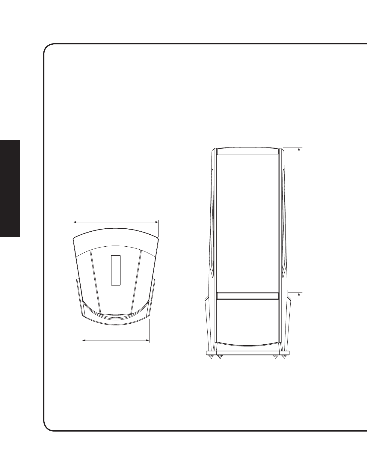
30.3” (76.9cm)
23Hz–22kHz ± 3dB
385 lbs. (175 kg)
4 Ohms
90dB @ 2.83 V/M
74.8”
(189.9cm)
23.8” (60.4cm)
23.6”
(59.9cm)
0
Page 29
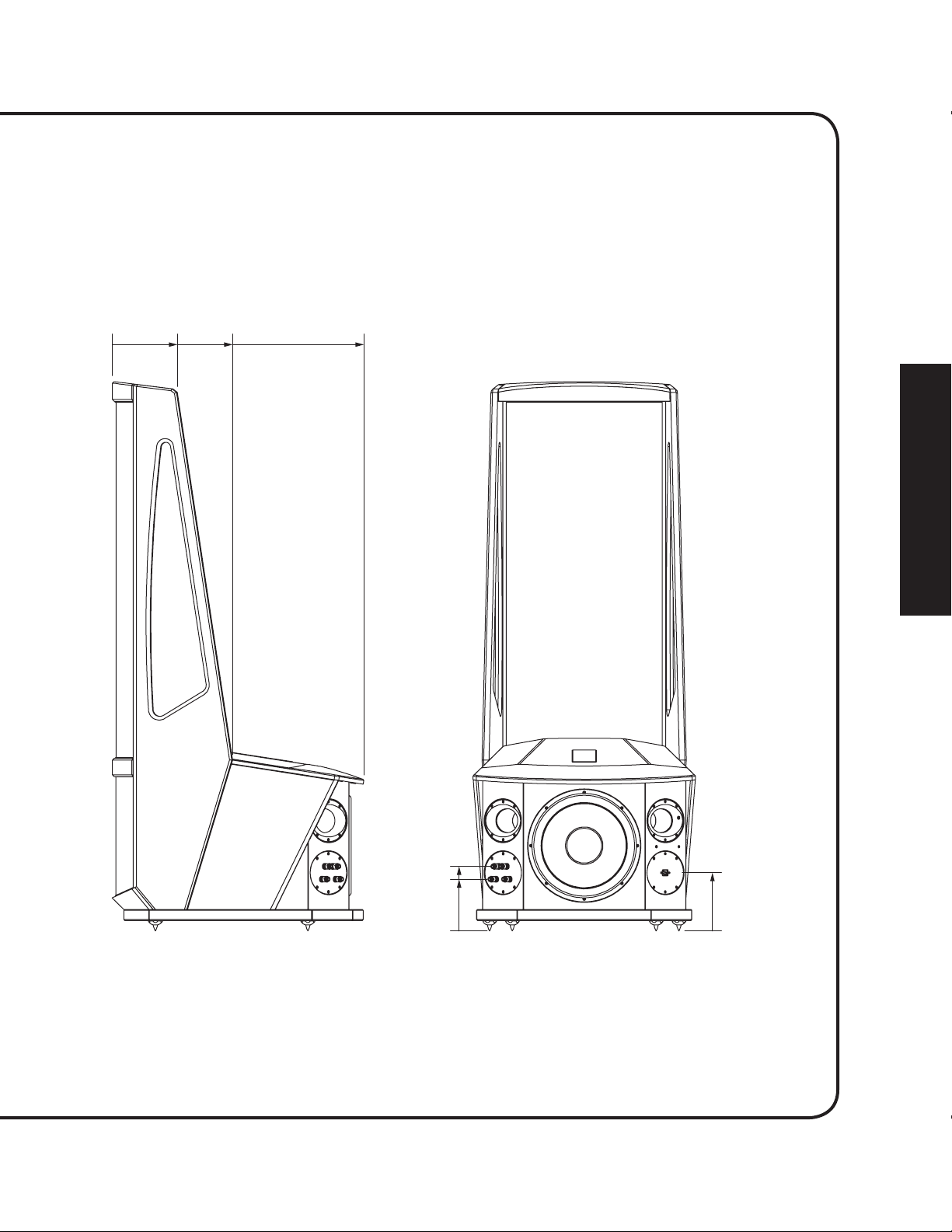
8.9”
(22.5cm)
16.4”
(41.6cm)
34.2”
(87cm)0
8.75”
(22.3cm)
7”
(17.9cm)
7.9”
(20.1cm)
0
0
Page 30
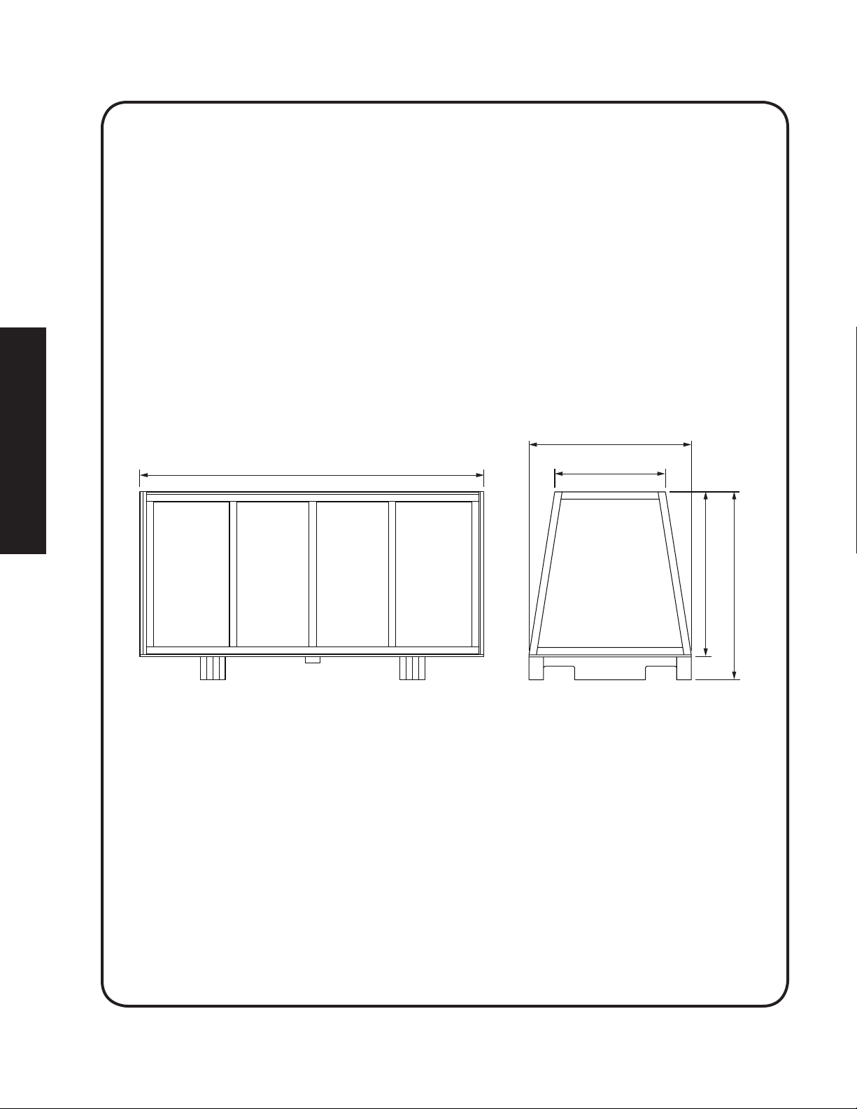
600 lbs. (273 kg)
39” (99cm)
82.6” (210cm)
26.6” (67.6cm)
39.7” (100.8cm)
45.17” (114.8cm)
Page 31

2x
x
>24”
(>61cm)
>24” (>61cm)
x
Page 32

Page 33

50–1,300W @ 4 Ohms
Page 34

Page 35

user’s manual
tm
English
®
Page 36

36
Page 37

CONTROLS AND CONNECTIONS
AC Power Connection
Because your MartinLogan Neolith speakers use an internal
power supply to energize their electrostatic cells they must be
connected to an AC power source. For this reason they are
provided with the proper IEC standard power cords. These
cords should be firmly inserted into the AC power receptacles
on the rear connection panel of the speakers, then to any convenient AC wall outlet. The Neolith’s integrate a signal sensing
power supply which will switch off after several minutes of no
music signal, and requires less than two seconds to recharge
the panels when a music signal is present.
Your Neolith speakers are wired for the power service supplied in
the country of original consumer sale. The AC power rating appli
cable to a particular unit is specified both on the packing carton
and on the serial number plate attached to the speaker. If you
remove your Neolith speakers from the country of original sale,
be certain that the AC power supplied in any subsequent loca
tion is suitable before connecting and operating the speakers.
Substantially impaired performance or severe damage may occur
to an Neolith speaker if operation is attempted from an incorrect
AC power source.
WARNING! The power cord should not be installed,
removed, or left detached from the speaker while the
other end is connected to an AC power source.
Signal Connection
Use the best speaker cables you can. The length and type of
speaker cable used in your system will have an audible effect.
Under no circumstance should a wire of gauge higher (thinner) than #16 be used. In general, the longer the length used,
the greater the necessity of a lower gauge, and the lower the
gauge, the better the sound, with diminishing returns setting in
around #8 to #12.
A variety of cables are available whose
better performance than standard heavy gauge wire. We have
verified this in many cases, and the improvements available
are often more noticeable than the differences between wires
of different gauge. The effects of cables may be masked if
equipment is not of the highest quality.
Connections are done at the signal input section on the rear
electronics panel of the Neolith. Use spade connectors for opti-
mum contact and ease of installation. Hand tighten the binding
posts, but do not overtighten—do not use a tool to tighten the
binding posts.
Be consistent when connecting the speaker cables to the signal
input terminals. Take care to assign the same color cable lead
to the (+) terminal on both the left and right channel speakers.
If bass is nonexistent and you cannot discern a tight, coherent
image, you may need to reverse the (+) and (–) leads on one
speaker to bring the system into proper polarity.
manufacturers claim
English
Figure 1. AC power connection.
WARNING! Turn your amplifier off before making or
breaking any signal connections!
Break-In
When you first begin to play your Neolith speakers, they will
sound a bit bass shy. This is due to the high quality, long-life
components used in our woofer. Our custom made woofer
requires approximately 72 hours of break-in at 90 dB (moderate listening levels) before any critical listening. The break-in
requirements of the crossover components (and, to a lesser
degree, the stator) are equivalent.
1
Page 38

Jumper Clips
In some countries laws prohibits MartinLogan from supplying
jumper clips. If none are included with your speakers please
refer to ‘Bi-Wire Connection’ for connection instructions.
Single Wire Connection
Please note the jumper clips included with the Neolith. These
clips attach the high and low frequency sections of the crossover. With these in place, connect the (+) wire from your
amplifier to either red binding post and the (–) wire from your
amplifier to either black binding post (see figure 2).
Bi-Wire Connection
This connection method replaces the jumper clips installed
on the binding posts with individual runs of speaker wire from
your amplifier. This doubles the signal carrying conductors
from the amplifier to the speaker, thus direct-coupling each
portion of the crossover to the amplifier.
To bi-wire you must first remove the jumper clips. Connect
one set of wires to the upper set of binding posts which connect to the electrostatic panel of the Neolith. Then connect a
second set of wires to the lower binding posts which connect
to the woofers. Next, connect both sets of wires to the appropriate terminals on your amplifier. Please take care to connect
both (+) wires to the (+) amplifier terminals and both (-) wires
to the (–) amplifier terminals. This is known as a parallel connection (see figure 3).
Passive Bi-Amplification
For those that desire ultimate performance, the Neolith may
be passively bi-amplified using the existing internal passive
crossover elements.
WARNING! Only after jumper clips are removed may
you connect individual runs of speaker cable from
your amplifiers to the high pass (ESL) and low pass
(WOOFER) input binding posts. Damage will occur to
This method takes the bi-wiring concept one step further.
You will have a dedicated channel of amplification directly
connected to the high and low pass sections of the Neolith
crossover. There are two different methods for bi-amping with
two stereo amplifiers. The first and most common is referred
to as Horizontal Bi-amping. The second method is referred to
as Vertical Bi-amping. With either method you may use two
your amplifiers if the jumper clips are not removed.
English
Figure 2. Single wire connection. Jumpers installed. One channel shown.
2
Figure 3. Bi-wire connection. One channel shown.
Page 39

stereo amplifiers or four mono amplifiers, or two mono amplifiers and one stereo amplifier. With either form of passive
bi-amplification, your preamplifier must have dual outputs. If
your preamplifier is not so equipped, you must either purchase
or construct a “Y” adapter.
Horizontal Passive Bi-Amplification
Horizontal bi-amping allows you to use two different types,
models, or brands of amplifiers (i.e. tubes on top, transistor on
the bottom). However, we recommend that you use two iden
tical amplifiers (i.e. same brand and model). If you must use
two different amplifiers, it is essential that they have the same
gain or that one of the two have adjustable gain so that you can
match their gain characteristics. If the amplifiers of choice do not
have the same gain characteristics, then a sonic imbalance will
occur. With horizontal bi-amping, one amplifier drives the high
pass (ESL) section while the second amplifier drives the low pass
(woofer) section. To horizontally bi-amp your Neolith’s you must
remove the jumper clips. Connect the low frequency amplifier
to the lower set of binding posts of both speakers. Connect the
high frequency amplifier to the upper set of binding posts. Next,
connect the left and right preamplifier outputs to the appropri
ate left and right inputs of both amplifiers (see figure 4).
Vertical Passive Bi-Amplification
The very nature of vertical bi-amping dictates that both amplifiers be identical. With vertical bi-amping, each of the stereo
amplifiers is dedicated to one speaker. For instance, the left
channel of each amplifier drives the low pass (WOOFER) section while the right channel drives the high pass (ESL) section.
To vertically bi-amp your Neolith’s you must loosen the binding posts and remove the jumper clips from both speakers.
Starting with one speaker, connect the right channel to the
lower binding posts and the left channel to the upper binding posts. Repeat the same procedure for the other speaker.
Connect the left preamplifier outputs to both inputs of the
left channel amplifier and the right preamplifier outputs
to both inputs of the right channel amplifier (see figure 5).
Active Bi-Amplification
Neolith’s internal crossover can not be bypassed and active biamplification is not possible.
-
Figure 4. Horizontal passive bi-amplification. One channel shown. Figure 5. Vertical passive bi-amplification. One channel shown.
English
3
Page 40

Top Panel Controls
Light Knob
The light control allows the Neolith’s light
to be turned on, off, or to be dimmed.
Multi-color Status Light
No color: No power, not plugged in.
Blue: Play mode. Neolith detects an audio
signal and is operating normally.
Red: Standby mode. This indicates the
Neolith does not detect an audio signal.
Flashing (various colors): Safe mode.
Neolith’s safe modes will cause the status LED to blink in various colors. When
this occurs the electrostatic panel and/
or woofers will not produce sound. The
primary cause of safe mode is one of
Neolith’s subsystems exceeding nominal
operating temperature range. Normal
operation will resume when available.
This can also occur after initial plug in
or while entering standby mode and will
clear upon music signal or standby mode.
English
Figure 6. Neolith control panel.
Low Bass and Distance Jumpers
Neolith features two crossover adjustments. Jumpers must be installed for
proper operation (figure 7). Make sure
jumpers are completely inserted.
Low Bass Output Jumpers
These jumpers reduce low bass output,
useful when adjusting for room gain (see
figures 8a–8c):
A –8dB
A+B –4dB
C 0dB
Listening Distance Jumpers
These jumpers adjust front woofer output to optimize woofer/panel integration
at various listening distances as measured
from the front of the electostatic panel (see
figures 9a–9c):
G 3 meters (or less)
D+F 4 meters
E+F 5 meters (or greater)
Figure 7. Neolith jumpers set for 0dB, 3 meters.
4
Page 41

Low Bass Output Jumpers
Figure 8a. Low Bass jumpers set for 0dB.
Listening Distance Jumpers
Figure 9a. Distance jumpers set for 3 meters.
Figure 8b. Low Bass jumpers set for –4dB.
Figure 9b. Distance jumpers set for 4 meters.
Figure 8c. Low Bass jumpers set for –8dB.
English
Figure 9c. Distance jumpers set for 5 meters.
5
Page 42

6
Page 43

PLACEMENT
Listening Position
Start with the rear of your speakers placed approximately two
to three feet from the front wall (the wall in front of the listening position) and the edge of the electrostatic stat panel about
two feet from the side walls. Your sitting distance should be
further than the distance between the speakers themselves.
You are trying to attain the impression of good center imaging
and stage width (see figure 10).
There is no exact distance between speakers and listener,
but there is a relationship. In long rooms, naturally, that relationship changes. The distance between the speakers will
be far less than the distance from you to the speaker system.
However, in a wide room, you will still find that if the distance
from the listener to the speakers becomes smaller than the
distance between the speakers themselves, the image will no
longer focus in the center.
Now that you have positioned your speaker system, spend
time listening. Wait to make any major changes in
setup for the next few days as the speaker
change subtly in its sound. Over the first 72 hours of play the
actual tonal quality will change slightly with deeper bass and
more spacious highs resulting. After a few days of listening you
can begin to make refinements and hear the differences.
your initial
system itself will
tions, brightness and confused imaging. Curtains, drapery and
objects such as bookshelves can be placed along the wall to
diffuse an overly reflective surface. A standard sheet rock or
textured wall is generally an adequate surface if the rest of the
room is not too bright and hard. Walls can also be too soft. If
the entire front wall consists of heavy drapery, your system can
sound dull. You may hear muted music with little ambience.
Harder surfaces will actually help in this case.
The front surface ideally should be one long wall without
any doors or openings. If you have openings, the reflection
and bass characteristics from each channel can be different.
The Side Walls
A good rule of thumb is to have the side walls as far away from
the speaker sides as possible. However, MartinLogan’s unique
controlled dispersion electrostatic transducer inherently minimizes side wall reflections—a position as little as two feet or
less from the side walls often proves adequate. Sometimes, if
the system is bright or the imaging is not to your liking, and the
side walls are very near, try putting curtains or softening material directly to the edge of each speaker. An ideal side wall,
however, is no side wall at all.
English
The Wall Behind the Listener
Near-field reflections can also occur from your back wall
(the wall behind the listening position). If your listening position is close to the back wall, these reflections can cause
problems and confuse imaging quality. It is better for the
wall behind you to be absorptive than to be reflective. If you
have a hard back wall and your listening position is close to
it, experiment with devices that will absorb information (i.e.
wall hangings and possibly even sound absorbing panels).
The Wall Behind the Speakers
The front surface, the wall behind the speakers, should not
be extremely hard or soft. A pane of glass will cause reflec-
Experimentation
Toe-in—Now you can begin to experiment. First begin by toe-
ing your speakers in towards the listening area and then facing
them straight into the room. You will notice the tonal balance
and imaging changing. You will notice that as the speakers are
toed-in, the system becomes slightly brighter than when toedout. This design gives you the flexibility to compensate for a
soft or bright room.
Generally it is found that the ideal listening position is with the
speakers slightly toed-in so that you are listening to the inner
third of the curved transducer section. A simple, yet effective
method to achieve proper toe involves sitting at the listening
position, holding a flashlight under your chin and pointing it at
each speaker. The reflection of the flashlight should be within
the inner third of the panel (see figure 11).
7
Page 44

2x
x
>24”
(>61cm)
>24” (>61cm)
x
English
Figure 10. Final placement.
8
Page 45

Tilting the Speakers Backwards and Forwards—As the
diagrams show in the Dispersion Interactions section of this
manual, the vertical dispersion is directional above and below
the stator panel itself. In some instances, if you are sitting close
to the floor, slight forward tilting of the speakers can enhance
clarity and precision.
Imaging—In their final location, your Neolith’s can have a
stage width somewhat wider than the speakers themselves.
On well recorded music, the instruments can extend beyond
the edges of each speaker (left and right), yet a vocalist should
appear directly in the middle. The size of the instruments
should be neither too large nor too small, subject to the intent
and results of each unique audio recording.
Additionally, you should find good clues as to stage depth.
Make sure that the vertical alignment, distance from the front
wall, and toe-in is exactly the same for both speakers. This will
greatly enhance the quality of your imaging.
Bass Response—Your bass response should neither be
one note nor should it be too heavy. It should extend to the
deepest organ passages and yet be tight and well defined.
Kick-drums should be tight and percussive—string bass notes
should be uniform and consistent throughout the entirety of
the run without booming or thudding.
Tonal Balance—Voices should be natural and full and cymbals should be detailed and articulate yet not bright and
piercing, pianos should have a nice transient characteristic and
deep tonal registers. If you cannot attain these virtues, read
the section on Room Acoustics. This will give you clues on
how to get closer to these ideal virtues.
Final Placement
Now experiment with placing the speakers farther apart. As
the speakers are positioned farther apart, listen again, not so
much for bass response but for stage width and good pinpoint
focusing. Your ideal listening position and speaker position
will be determined by:
• Tightness and extension of bass response
• Width of the stage
• Pinpoint focusing of imaging
Once you have determined the best of all three of these
considerations, you will have your best speaker location.
The Extra “Tweak”
This extra “tweak” may be useful when your speakers are
placed in a dedicated listening room. Use the following procedure and measurements for your speakers placement to see
what can happen to your system’s performance. These formulas will help determine optimum placement of your speakers
to minimize standing waves.
1 Distance from the front wall (in front of the listening
position) to the center of the curvilinear transducer: To
determine distance from the front wall, measure the ceiling height (inches) and multiply the figure by 0.618 (i.e.
ceiling height (inches) x 0.618 = the distance from the
front wall to the center of the curvilinear transducer).
2 Distance from the side-walls to the center of the curvilin-
ear transducer: To determine distance from the side walls,
measure the width of your room in inches and divide by
18. Next, multiply the quotient by 5 (i.e. room width in
inches / 18 x 5 = the distance from the side-walls to the
center of the curvilinear transducer).
English
After the full break in period, obtaining good wall treatments,
and the proper toe-in angle, begin to experiment with the distance from the wall behind the speakers. Move your speaker
slightly forward into the room. What happened to the bass
response? What happened to the imaging? If the imaging is
more open and spacious and the bass response is tightened,
that is a superior position. Move the speakers back six inches
from the initial setup position and again listen to the imaging
and bass response. There will be a position where you will
have pinpoint imaging and good bass response. That position
is the point of the optimal placement from the front wall.
Enjoy Yourself
The Neolith is a very refined speaker and benefits from care in
setup. With these tips in mind you will find, over your months
of listening, that small changes can result in measurable differences. As you live with your speakers, do not be afraid to
experiment with their positioning until you find the optimal
relationship between your room and speaker system that gives
to you the best results. Your efforts will be rewarded.
9
Page 46

English
Figure 11. Flashlight toe-in technique.
10
Page 47

English
11
Page 48

12
Page 49

ROOM ACOUSTICS
Your Room
This is one of those areas that requires both a little background
to understand and some time and experimentation to obtain
the best performance from your system. Your room is actually
a component and an important part of your system. This component is a very large variable and can dramatically add to, or
subtract from, a great musical experience.
All sound is composed of waves. Each note has its own wave
size, with the lower bass notes literally encompassing from 10’
feet to as much as 40’ feet. Your room participates in this wave
experience like a three dimensional pool with waves reflecting
and becoming enhanced depending on the size of the room
and the types of surfaces in the room.
Remember, your system can literally generate all of the information required to recreate a musical event in time, space,
and tonal balance. Ideally, your room should not contribute
to that information. However, every room contributes to the
sound to some degree. Fortunately MartinLogan had designed
the Neolith to minimize these anomalies
Let’s talk about a few important terms before we begin.
occur in the mid and high frequencies. This is where voice and
frequencies as high as the cymbals occur.
Resonant Surfaces and Objects
All of the surfaces and objects in your room are subject to
the frequencies generated by your system. Much like an
instrument, they will vibrate and “carry on” in syncopation with the music, and contribute in a negative way to the
music. Ringing, boominess, and even brightness can occur
simply because they are “singing along” with your music.
Resonant Cavities
Small alcoves or closet type areas in your room can be chambers that create their own “standing waves” and can drum
their own “one note” sounds.
Clap your hands. Can you hear an instant echo respond back?
You have near-field reflections. Stomp your foot on the floor.
Can you hear a “boom”? You have standing waves or large
panel resonances such as a poorly supported wall. Put your
head in a small cavity area and talk loudly. Can you hear a
booming? You’ve just experienced a cavity resonance.
English
Rules of Thumb
Terminology
Standing Waves
The parallel walls in your room will reinforce certain notes to
the point that they will sound louder than the rest of the audio
spectrum and cause “one note bass”, “boomy bass” or “bloated bass”. For instance, 100Hz represents a 10 feet wavelength.
Your room will reinforce that specific frequency if one of the
dominant dimensions is 10 feet. Large objects in the room
such as cabinetry or furniture can help to minimize this potential problem. Some serious “audiophiles” will literally build a
special room with no parallel walls just to help eliminate this
phenomenon.
Reflective Surfaces (near-field reflections)
The hard surfaces of your room, particularly if close to your
speaker system, will reflect some waves back into the room
over and over again, confusing the clarity and imaging of your
system. The smaller sound waves are mostly affected here, and
Hard vs. Soft Surfaces
If the front or back wall of your listening room is soft, it might
benefit you to have a hard or reflective wall in opposition. The
ceiling and floor should follow the same basic guideline as
well. However, the side walls should be roughly the same in
order to deliver a focused image.
This rule suggests that a little reflection is good. As a matter of
fact, some rooms can be so “over damped” with carpeting,
drapes and sound absorbers that the music system can sound
dull and lifeless. On the other hand, rooms can be so hard that
the system can sound like a gymnasium with too much reflection and brightness. The point is that balance is the optimum
environment.
Breakup Objects
Objects with complex shapes, such as bookshelves, cabinetry
and multiple shaped walls can help break up those sonic gremlins and diffuse any dominant frequencies.
13
Page 50

English
Solid Coupling
Your loudspeaker system generates frequency vibrations or
waves into the room. This is how it creates sound. These vibrations vary from 20 per second to 20,000 per second. If your
speaker system is not securely planted on the floor or solid
surface, it can shake as it produces sound and, consequently,
the sound can be compromised. If your speaker is sitting on
the carpet and only foot gliders are used, the bass can be ill
defined and even boomy. The use of spikes is recommended
to insure secured footing for your speakers. (See ‘Solid Footing’
for spike information and installation instructions).
Dipolar Speakers and Your Room
MartinLogan electrostatic loudspeakers are known as dipolar
radiators. This means that they produce sound from both their
fronts and their backs. Consequently, musical information is
reflected by the wall behind them and may arrive, either in
or out of step, with the information produced by the front of
the speaker.
The low frequencies can either be enhanced or nulled by
the position from the front wall. Your Neolith’s have been
designed to be placed two to three feet from the front wall (the
wall in front of the listening position) to obtain the best results;
however, your room may see things differently. So listening to
the difference of the bass response as a result of the changes in
distance from the front wall can allow you to get the best combination of depth of bass and tonal balance.
Now that you know about reflective surfaces and resonant
objects, you can see how the midrange and high frequencies
can be affected. The timing of the initial wave as it radiates
to your ears, and then the reflected information as it arrives
at your ears later in time, can result in confusion of the precious timing information that carries the clues to imaging.
Consequently the result is blurred imaging and excessive
brightness. Soft walls, curtains, wall hangings, or sound dampeners (your dealer can give you good information here) can be
effective if these negative conditions occur.
Solid Footing
For your convenience Neolith ships with caster wheels
installed. After living and experimenting with your speaker’s
Figure 12. The ETC™ Spike.
placement you will want to use the ETC (energy transfer
coupler) spikes supplied with the Neolith. With the use of
these spikes, the Neolith will become more firmly planted
on the floor and, consequently, bass will tighten and imaging will become more coherent and detailed. It is best not to
implement the spikes, however, until you are secure in the
positioning, as the spikes can damage the floor if the speaker is
moved. The feet that attach to the bottom of the Neolith use a
common 3/8 - 16 thread (see figures 12 & 13).
Spike Installation Instructions:
1 Carefully tilt the speaker to gain access to the bottom. This
will require at least 2 people.
2 Remove existing feet or casters. Thread new spikes into
holes and screw them in all of the way. If the speaker
does not sit level loosen one spike until level is achieved.
3 Tighten the jam nut snugly by hand. Do not over tighten
the nut.
4 Right the speaker. Caution: Make sure your hands and
any cabling are clear of the spikes. Do not slide speaker as
spikes are sharp and can damage your floor or carpet.
5 Adjust to level by rotating spikes. Tighten the jam nut
securely when satisfied that speaker is level. Caution:
Walking the speaker may result in a broken spike.
14
Page 51

Figure 13. Installing the ETC spikes.
English
15
Page 52

16
Page 53

DISPERSION INTERACTIONS
Controlled Horizontal Dispersion
Your Neolith’s launch a 30 degree horizontal dispersion pattern. This horizontal dispersion field gives a choice of good
seats for the performance while minimizing interactions with
side walls (figure 18). Make sure both speakers stand exactly at the same vertical angle, otherwise the image can be
skewed or poorly defined. The wave launch of both speakers
is extremely accurate in both the time and spectral domain.
Consequently, small refined adjustments can result in noticeable sonic improvements.
Controlled Vertical Dispersion
As seen in the illustrations, your Neolith speakers project a controlled dispersion pattern (figure 19). This vertical dispersion
profile minimizes interactions with the floor and the ceiling.
Figure 14–15. As can be seen here, point
source concepts invite a great deal of room
interaction. While delivering good frequency
response to a large listening audience, imaging
is consequently confused and blurred.
Three Major Types of Dispersion
It is a known fact that as the sound wave becomes progressively smaller than the transducer producing it, the dispersion
of that wave becomes more and more narrow, or directional.
This fact occurs as long as the transducer is a flat surface. Large
flat panel speakers exhibit venetian blind effects due to this
phenomenon. This is one reason why many manufacturers opt
for small drivers (i.e. tweeters and midrange) to approximate
what is known as a point source wave launch.
Historically, most attempts to achieve smooth dispersion from
large flat panel transducers resulted in trade-offs. After exhaustive testing of many different methods, we conceived an
elegantly simple, yet intensely hand crafted process. By curving
the radiating surface, we create the effect of a horizontal arc.
This allows the engineers at MartinLogan to control the high
frequency dispersion pattern of our transducers.
English
Figure 16–17. Even though they suffer from
“venetian blind” effect, angled multiple panel
speakers can deliver good imaging, but only to
specific spots in the listening area.
Figure 18–19. A controlled 30 degree cylindrical wave-front, a MartinLogan exclusive, offers
optimal sound distribution with minimal room
interaction. The result is solid imaging with a
wide listening area.
17
Page 54

18
Page 55

HOME THEATER
It had long been the practice of stereo buffs to connect their
television to a stereo system. The advantage was the use of the
larger speakers and more powerful amplifier of the stereo system. Even though the sound was greatly improved, it was still
mono and limited by the broadcast signal.
In the late 1970’s and early 1980’s two new home movie formats became widely available to the public: VCR and laser disc.
By 1985, both formats had developed into very high quality
audio/video sources. In fact, the sonic performance of some
video formats exceeded audio-only formats. Now, with theater-quality sound available at home, the only element missing
was the "surround sound" presentation found in movie houses.
Fortunately, Dolby and DTS encoded movies (including almost
all films) have the same surround sound information encoded
on home releases as the theatrical release. All that is required
to retrieve this information is a decoder and additional speakers and amps to reproduce it.
Home theater is a complex purchase and we recommend that
you consult your local MartinLogan dealer, as they are well
versed in this subject.
Surround Speakers
We recommend (along with the film industry) that the surround speakers play down to at least 80 Hz. Surround speakers
contain the information that makes it appear that planes are
flying over your head. Some may suggest that this is the place
to save money and purchase a small, inexpensive speaker. If
you choose to do so, be prepared to upgrade in the future as
discrete multi-channel digital encoding is proliferating rapidly
and the demands on surround speakers have increased.
Subwoofer
With any good surround system you will need one or more
high-quality subwoofers (the .1 in a 5.1 channel surround system). Most movie soundtracks contain large amounts of bass
information as part of the special effects. Good subwoofers
will provide a foundation for the rest of the system.
English
Each piece of a surround system can be purchased separately.
Take your time and buy quality. No one has ever complained
that the movie was too real. The following list and descriptions
will give you only a brief outline of the responsibilities and
demands placed on each speaker.
Front Left and Front Right
If these speakers will be the same two used for your stereo
playback, they should be of very high quality and able to play
loudly (over 102 dB) and reproduce bass below 80 Hz.
Center Channel
This is the most important speaker in a home theater
system, as almost all of the dialogue and a large portion of the
front speaker information is reproduced by the center channel.
It is important that the center speaker be extremely accurate
and mate well the front speakers, and that it is recommended
for use as a center speaker. This is not the place to cut corners.
Figure 20. Neolith speakers as front channels, MartinLogan electrostatic speakers as center channel and rear and side surround (effects)
channels, and MartinLogan subwoofers as LFE (effects) channel.
19
Page 56

20
Page 57

ELECTROSTATIC ADVANTAGES
How can sound be reproduced by something that you are
able to see through? Electrostatic energy makes this possible.
Where the world of traditional loudspeaker technology deals
with cones, domes, diaphragms and ribbons that are moved
with magnetism, the world of electrostatic loudspeakers deals
with charged electrons attracting and repelling each other.
To fully understand the electrostatic concept, some background information will be helpful. Remember when you
learned in a science or physics class that like charges repel
each other and opposite charges attract each other? Well,
this principle is the foundation of the electrostatic concept.
An electrostatic transducer consists of three pieces: stators, the
diaphragm and spacers (see figure 21). The diaphragm is what
actually moves to excite the air and create music. The stator’s
job is to remain stationary, hence the word stator, and to provide a reference point for the moving diaphragm. The spacers
provide the diaphragm with a fixed distance in which to move
between the stators.
As your amplifier sends music signals to an electrostatic speaker,
these signals are changed into two high-voltage signals that are
equal in strength but opposite in polarity. These high voltage
signals are then applied to the stators. The resulting electrostatic
field, created by the opposing high voltage on the stators, works
simultaneously with and against the diaphragm, consequently
moving it back and forth, producing music. This technique is
known as push-pull operation and is a major contributor to the
sonic purity of the electrostatic concept due to its exceptional
linearity and low distortion.
Since the diaphragm of an electrostatic speaker is uniformly
driven over its entire area, it can be extremely light and flexible.
This allows it to be very responsive to transients, thus perfectly
tracing the music signal. As a result, great delicacy, nuance and
clarity is possible. When you look at the problems of traditional
electromagnetic drivers, you can easily see why this is so beneficial. The cones and domes which are used in traditional
electromagnetic drivers cannot be driven uniformly because of
their design. Cones are driven only at the apex. Domes are driven at their perimeter. As a result, the rest of the cone or dome
is just “along for the ride”. The very concept of these
drivers requires that the cone or dome be perfectly rigid,
damped and massless. Unfortunately, these conditions are not
available in our world today.
To make these cones and domes move, all electromagnetic
drivers must use voice coils wound on formers, spider assemblies, and surrounds to keep the cone or dome in position (see
figure 22). These pieces, when combined with the high mass
of the cone or dome materials used, make it an extremely
complex unit with many weaknesses and potential for failure.
These faults contribute to the high distortion products found
in these drivers and is a tremendous disadvantage when you
are trying to change motion as quickly and as accurately as a
loudspeaker must (40,000 times per second!).
English
Figure 21. Cut away view of an XStat electrostatic transducer. Notice
the simplicity due to minimal parts usage.
Figure 22. Cut away view of a typical moving coil driver. Notice the
complexity due to the high number of parts.
21
Page 58

Full Range Operation
Another significant advantage of MartinLogan’s exclusive
transducer technology reveals itself when you look at examples of other loudspeaker products on the market today.
The Neolith uses no crossover networks above 250–400 Hz
because they are not needed. The Neolith consists of a single,
seamless electrostatic membrane reproducing all frequencies
above 250–400 Hz simultaneously. How is this possible?
First we must understand that music is not composed of separate
high, mid and low frequencies. In fact, music is comprised of a
single waveform with all frequencies interacting simultaneously.
drivers must be designed to operate within a narrow, fixed
bandwidth of the frequency range, and then combined electrically so that the sum of the parts equals the total signal. While
nice in theory, we must deal with real-world conditions.
In order to use multiple drivers, a crossover network is enlisted to attempt a division of the complex musical signal into
the separate pieces (usually highs, mids, and lows) that each
specific driver was designed to handle. Unfortunately, due
to the phase relationships that occur within all crossover networks and during the acoustical recombination process,
nonlinearities and severe degradation of the music signal take
place in the ear’s most critical zone (see figure 23).
English
The electrostatic transducer of the Neolith essentially acts as
an exact opposite of the microphones used to record the original event. A microphone, which is a single working element,
transforms acoustic energy into an electrical signal that can be
amplified or preserved by some type of storage media. The
Neolith’s electrostatic transducer transforms electrical energy
from your amplifier back into acoustical energy.
Due to the limitations of electromagnetic drivers, no single
unit can reproduce the full range of frequencies. Instead, these
MartinLogan Neolith
ESL
Panel
Critical Zone
The Neolith’s electrostatic transducer can single-handedly
reproduce all frequencies above 250–400 Hz simultaneously.
You have in one transducer the ability to handle in elegant
simplicity the critical frequencies above 250–400 Hz.
The crossover phase aberrations that are associated with traditional tweeter, midrange, and woofer systems are eliminated.
The result is a dramatic improvement in imaging and staging
performance due to the minutely accurate phase relationship
of the full-range panel wave launch.
Conventional Loudspeaker
Tweeter
crossover point (2,000–5,000 Hz)
22
Woofer
crossover point (250–400 Hz)
Figure 23. This diagram illustrates
how a conventional speaker system
must use multiple crossover networks
that have negative effects on the
musical performance.
crossover point (100–400 Hz)
Midrange
Woofer
Page 59

English
23
Page 60

24
Page 61

MARTINLOGAN EXCLUSIVES
XStat Transducer
XStat transducers incorporate a myriad of technology and
design innovations including CLS, MicroPerf, Generation 2
Diaphragms, ClearSpars™, and Vacuum Bonding.
CLS (Curvilinear Line Source)
Since the beginning of audio, achieving smooth dispersion has
been a problem for all designers. Large panel transducers present unique challenge because the larger the panel, the more
directional the dispersion pattern becomes.
Wide range electrostats have long been one of the most
problematic transducers because they attain their full range
capabilities via a large surface area. It looked as if they were in
direct conflict to smooth dispersion and almost every attempt
to correct this resulted in either poor dispersion or a serious
compromise in sound quality.
After extensive research, MartinLogan engineers discovered
an elegantly simple solution to achieve a smooth pattern of
dispersion without degrading sound quality. By curving the
horizontal plane of the electrostatic transducer, a controlled
horizontal dispersion pattern could be achieved, yet the purity of the almost massless electrostatic diaphragm remained
uncompromised. After creating this technology, MartinLogan
developed the production capability to bring it out of the
laboratory and into the market place. You will find this proprietary MartinLogan technology used in all of our electrostatic
products. It is one of the many reasons behind our reputation for high quality sound with practical usability. This is also
why you see the unique “see through” cylindrical shape of
MartinLogan products.
Generation 2 Diaphragm
Neolith’s diaphragm employs an extremely sophisticated conductive coating applied to the polymer surface at an atomic
level using a plasma bonding process. A proprietary compound
is driven into the surface of the polymer film in an oxygen free
argon chamber. This process allows extremely uniform surface
resistivity characteristics, an optically transparent surface, and
a nearly massless diaphragm. This uniform surface resistivity
controls the electrostatic charge on the diaphragm surface and
regulates its migration. As a result, no discharging or “arcing”
can occur.
MicroPerf Stator
Sleek. Compact. MicroPerf stator technology, featured in
all XStat transducers, reveals more open playable area in
each panel, offering increased performance from even more
compact stat panels. It is significant to note that the XStat transducer in the radical new Neolith loudspeaker supports the
bandwidth and dynamics associated with traditional electrostatic panels nearly twice its size.
Vacuum Bonding
To achieve the power, precision, and strength of the XStat
transducer, two insulated high-purity carbon steel stators along
with a proprietary plasma bonded diaphragm and ClearSpar
spacers are fused into a curved geometry with an aerospace
adhesive whose strength exceeds that of welding. Our proprietary Vacuum Bonding process guarantees uniform diaphragm
tensioning and extremely precise construction tolerances,
resulting in unequivocal precision, linearity and efficiency.
English
25
Page 62

26
Page 63

ELECTROSTATIC LOUDSPEAKER HISTORY
In the late 1800’s, any loudspeaker was considered exotic.
Today, we take the wonders of sound reproduction for granted.
It was 1880 before Thomas Edison had invented the
first phonograph. This was a horn-loaded diaphragm
that was excited by a playback stylus. In 1898, Sir Oliver
Lodge invented a cone loudspeaker, which he referred to
as a “bellowing telephone”, that was very similar to the conventional cone loudspeaker drivers that we know today.
However, Lodge had no intention
for his device to reproduce music
because in 1898 there was no way
to amplify an electrical signal! As
a result, his speaker had nothing
to offer over the acoustical gramophones of the period. It was not
until 1906 that Dr. Lee DeForrest
invented the triode vacuum tube.
Before this, an electrical signal could not be amplified. The
loudspeaker, as we know it today, should have ensued then,
but it did not. Amazingly, it was almost twenty years before
this would occur.
In 1921, the electrically cut phonograph record became
a reality. This method of recording was far superior to the
mechanically cut record and possessed almost 30 dB of
dynamic range. The acoustical gramophone couldn’t begin to
reproduce all of the information on this new disc. As a result,
further developments in loudspeakers were needed to cope
with this amazing new recording medium.
By 1923, the decision was made to develop a complete musical playback system consisting of an electronic phonograph
and a loudspeaker to take advantage of the new recording
medium. The project to two young engineers, C. W. Rice and
E. W. Kellogg.
Rice and Kellogg had a well equipped laboratory at their disposal. This lab possessed a vacuum tube amplifier with an unheard
of 200 watts, a large selection of the new electrically cut phonograph records and a variety of loudspeaker prototypes that
had been collecting over the past decade. Among these were
Lodge’s cone, a speaker that used compressed air, a corona discharge (plasma) speaker, and an electrostatic speaker.
Rice and Kellogg had
narrowed the field of
“contestants down” to the
cone and the electrostat.
After a short time, Rice and Kellogg had narrowed the field of
“contestants” down to the cone and the electrostat. The outcome would dictate the way that future generations would
refer to loudspeakers as being either “conventional” or “exotic”.
Their electrostat was something to behold. This enormous
bipolar speaker was as big as a door. The diaphragm, which
was beginning to rot, was made of a pig intestine that was covered with fine gold leaf to conduct the audio signal.
When Rice and Kellogg began playing
the new electrically cut records through
the electrostat, they were stunned and
impressed. The electrostat performed
splendidly. They had never heard instrumental timbres reproduced with such
realism. This system sounded like real
music rather than the honking, squawking rendition of the acoustic gramophone. Immediately, they
knew they were on to something big. The acoustic gramophone was destined to become obsolete.
Due to Rice and Kellogg’s enthusiasm, they devoted a considerable amount of time researching the electrostatic design.
However, they soon encountered the same difficulties that
even present designers face; planar speakers require a very
large surface area to reproduce the lower frequencies of the
audio spectrum. Because the management considered large
speakers unacceptable, Rice and Kellogg’s work on electrostatics would never be put to use for a commercial product.
Reluctantly, they advised management to go with the cone.
For the next 30 years, the electrostatic design lay dormant.
During the Great Depression of the 1930’s, consumer audio
almost died. The new electrically amplified loudspeaker
never gained acceptance, as most people continued to use
their old Victrola-style acoustic gramophones. Prior to the
end of World War II, consumer audio saw little, if any, progress. However, during the late 1940’s, audio experienced
a great rebirth. Suddenly there was tremendous interest in
audio products, and with that, a great demand for improved
audio components. No sooner had the cone become established than it was challenged by products developed during
this new rebirth.
English
27
Page 64

English
In 1947, Arthur Janszen, a young Naval engineer, took part in
a research project for the Navy. The Navy was interested in
developing a better instrument for testing microphone arrays.
The test instrument needed an extremely accurate speaker,
but Janszen found that the cone speakers of the period were
too nonlinear in phase and amplitude response to meet his
criteria. Janszen believed that electrostats were inherently
more linear than cones, so he built a model using a thin plastic
diaphragm treated with a conductive coating. This model confirmed Janszen’s beliefs, for it exhibited remarkable phase and
amplitude linearity.
Janszen was so excited with the results that he continued
research on the electrostatic speaker on his own time. He
soon thought of insulating the stators to prevent the destructive effects of arcing. By 1952, he had an electrostatic tweeter
element ready for commercial production. This new tweeter
soon created a sensation among American audio hobbyists.
Since Janszen’s tweeter element was limited to high frequency reproduction, it often
found itself used in conjunction with woofers—most notably, those from Acoustic
Research. These systems were highly
regarded by all audio enthusiasts.
As good as these systems were, they would
soon be surpassed by another electrostatic
speaker.
In 1955, Peter Walker published three articles regarding
electrostatic loudspeaker design in Wireless World, a British
magazine. In these articles, Walker demonstrated the benefits
of the electrostatic loudspeaker. He explained that electrostatics permit the use of diaphragms that are low in mass, large
in area and uniformly driven over their surfaces by electrostatic forces. Due to these characteristics, electrostats have the
inherent ability to produce a wide bandwidth, flat frequency
response with distortion products being no greater than the
electronics driving them.
By 1956, Walker backed up his articles by introducing a consumer product, the now famous Quad ESL. This speaker
immediately set a standard of performance for the audio
industry due to its incredible accuracy. However, in actual
use, the Quad had a few problems. It could not be played very
loud, it had poor bass performance, it presented a difficult
load that some amplifiers did not like, its dispersion was very
directional and its power handling was limited to around 70
These developments allow the
consumer to own the highest
performance loudspeaker
products ever built.
watts. As a result, many people continued to use box speakers
with cones.
In the early 1960’s Arthur Janszen joined forces with the KLH
loudspeaker company, and together they introduced the KLH
9. Due to the large size of the KLH 9, it did not have as many
sonic limitations as the Quad. The KLH 9 could play markedly louder and lower in frequency than the Quad ESL. Thus a
rivalry was born.
Janszen continued to develop electrostatic designs. He
was instrumental in the design of the Koss Model One, the
Acoustech and the Dennesen speakers. Roger West, the chief
designer of the Janszen Corporation, became the president
of Sound Lab. When Janszen Corporation was sold, the RTR
loudspeaker company bought half of the production tooling.
This tooling was used to make the electrostatic panels for the
Servostatic, a hybrid electrostatic system that was Infinity’s
first speaker product. Other companies soon followed; each with
their own unique applications of
the technology. These include
Acoustat, Audiostatic, Beverage,
Dayton Wright, Sound Lab and
Stax, to name a few.
Electrostatic speakers have progressed and prospered because they actually do what Peter
Walker claimed they would. The limitations and problems
experienced in the past were not inherent to the electrostatic
concept. They were related to the applications of these concepts.
Today, these limitations have been resolved. Advancements
in materials due to the U.S. space program give designers the
ability to harness the superiority of the electrostatic principle.
Today’s electrostats use advanced insulation techniques or
provide protection circuitry. The poor dispersion properties of
early models have been addressed by using delay lines, acoustical lenses, multiple panel arrays or, as in our own products,
by curving the diaphragm. Power handling and sensitivity have
also been increased.
These developments allow the consumer the opportunity to
own the highest performance loudspeaker products ever built.
It’s too bad Rice and Kellogg were never able to see just how
far the technology would be taken.
28
Page 65

English
29
Page 66

30
Page 67

FREQUENTLY ASKED QUESTIONS
How do I clean my speakers?
Use a dust free cloth or a soft brush to remove the dust
from your speakers. We also recommend a specialty cloth
(available at the Xtatic shop at www.martinlogan.com)
that cleans your speakers better than anything else we
have tried. For the wood surfaces it is acceptable to slightly dampen the cloth. Do not spray any kind of cleaning
agent on or in close proximity to the electrostatic element.
Avoid the use of ammonia based products or silicone oil
on the wood parts.
What is the advantage of ESL?
Since the diaphragm is uniformly driven over its entire
surface—unlike a tweeter that is only driven at its edges—
it is the only technology that can be made large enough to
play bass, yet is still light enough for high frequencies. This
unique property allows for the elimination of high frequency crossover points and their associated distortions.
What size amplifier should I use?
We recommend an amplifier with 50 to 1,300 watts per
channel (at 4 Ohms) for most applications. Our hybrid
designs will perform well with either a tube or transistorized
amplifier, and will reveal the sonic character of either type.
However, it is important that the amplifier be stable operat
ing into varying impedance loads: an ideally stable amplifier
will typically be able to deliver nearly twice its rated watt
age into 4 Ohms and should again increase into 2 Ohms.
Could you suggest a list of suitable electronics and cables
that would be ideal for MartinLogan speakers?
The area of electronics and cable choice is probably
the most common type of question that we receive. It is
also the most subjective. We have repeatedly found that
brands that work well in one setup will drive someone
else nuts in another. We use many brands with great success. Again, we have no favorites; we use electronics and
cables quite interchangeably. We would suggest listening
to a number of brands—and above all else— trust your
ears. Dealers are always the best source for information
when purchasing additional audio equipment.
Is there likely to be any interaction between my speakers
and the television in my Audio/Video system?
Actually, there is less interaction between a television and
an electrostatic speaker than between a television and a
conventional system. However, we do recommend that
you keep your speakers at least one foot away from the
television because of the dynamic woofer they employ.
In the case of our center channel speakers, however, they
are fully shielded and can go anywhere.
Will my electric bill go ‘sky high’ by leaving my speakers
plugged in all the time?
No. There is circuitry to turn off the static charge when
not in use; however, actual consumption will remain
close to the same. The primary purpose of the sensing
circuitry is to prevent dust collection on the electrostatic
element.
If the diaphragm is punctured with a pencil or similar
item, how extensive would the damage to the speaker be?
Our research department has literally punctured hundreds of holes in a diaphragm, neither affecting the
quality of the sound nor causing the diaphragm to rip.
However, you will be able to see the actual puncture and
it can be a physical nuisance. If this is the case, replacing
the electrostatic transducer will be the only solution.
Will exposure to sunlight affect the life or performance of
-
my speakers?
-
We recommend that you not place any loudspeaker in
direct sunlight. The ultraviolet (UV) rays from the sun
can cause deterioration of grill cloth, speaker cones, etc.
Small exposures to UV will not cause a problem. In general, the filtering of UV rays through glass will greatly reduce
the negative effects on the electrostatic membrane itself.
Will excessive smoke or dust cause any problems with my
electrostatic speakers?
Exposure to excessive contaminants such as smoke
or dust may potentially affect the performance of the
electrostatic membrane, and may cause discoloration
of the diaphragm membrane. When not in use for
extended periods, you should unplug the speakers and
cover them with the plastic bags in which the speakers
were originally packed. It is a good idea to vacuum the
electrostatic portion of each speaker three or four times a
year. See the vacuuming FAQ.
English
31
Page 68

A problem has recently developed with my MartinLogan
speakers. The right speaker seems to be hissing even
when the amplifier and such are not connected. I was
wondering if this sounds like any problem you have
encountered previously and have a simple solution for or
might it be something which will need to be looked into
more carefully.
Your speakers are dusty. See the vacuuming FAQ. The
electrostatic charge on the element has attracted airborne dust or pollen. Since 1993, all of our speakers
have been built with a charging circuit board that only
charges the electrostatic element when music plays. At
other times they are not charged and cannot collect dust.
You can get the same benefit by simply unplugging them
whenever they are not in use. A power strip is an easy
way to do that.
Could my children, pets, or myself be shocked by the
high-voltage present in the electrostatic panel?
No. High voltage with low current is not dangerous. As a
matter of fact, the voltage in our speakers is 10 times less
than the static electricity that builds up on the surface of
your television screen.
How do MartinLogan speakers hold up over a long term in
the humidity of tropical climates?
We should tell you that MartinLogan indeed has a very
substantial number of customers in tropical regions of
the world. Our speakers have been serving them nicely
for many years. This concern may have come from our
earlier design of speakers, which were charged continuously. Since 1993, all of our speakers have been designed
so that they only charge the panel while music is being
played. This improvement has made a tremendous difference in the consistent performance of our product. There
may be a little more maintenance involved in humid
regions when not in an air conditioned environment.
Simply enough, the concern is to keep the electrostatic
panels dust free. Humidity will combine with any dust on
the panel to make it slightly conductive. This will result
in a slight pathway for the charge to leave the membrane
of the speaker. The solution is simple. They only require
occasional vacuuming with a strong vacuum hose.
How do I vacuum my MartinLogan speakers?
Vacuuming will be most effective if the speakers have
been unplugged for six hours to twelve hours (or overnight). You need not worry about the vacuum pressure
damaging the "delicate" membrane. It is extraordinarily
durable. Dirt and dust may be vacuumed off with a brush
attachment connected to your vacuum cleaner, or you
may blow them off with compressed air. When vacuuming
or blowing off your panels do so to both sides, but focus
the majority of your attention on the front of the panels.
Should I unplug my speakers during a thunderstorm?
Yes, or before. It’s a good idea to disconnect all of your
audio/video components during stormy weather.
English
32
Page 69

English
33
Page 70

34
Page 71

TROUBLESHOOTING
No Output
• Check that all your system components are turned on.
• Check Neolith status LED. It should be blue. Please see
the Top Panel Controls section of manual.
• Check your speaker wires and connections.
• Check all interconnecting cables.
• Try hooking up a different set of speakers. The lack of
output could point to a problem with other equipment in
your system (amp, pre-amp, processor, etc.)
Weak or no Output from Electrostatic Panel, Loss of Highs
• Check the power cord. Is it properly connected to the
speaker and to the wall?
• Is the power cord connected to a switched outlet?
• Check Neolith status LED. It should be blue. Please see
the Top Panel Controls section of manual.
• Dirt and dust may need to be vacuumed off. Please see
the FAQ regarding vacuuming.
• If using a single-wire connection, check to make sure that
the jumper clips are in place and that the binding posts
are firmly hand-tightened.
• Check the binding posts. Are the dirty? If so clean them
with rubbing alcohol.
• Check the binding posts. Are the loose? Make sure they
are firmly hand-tightened.
• Has a foreign substance (such as a household cleaning
chemical or soap) been applied to the panel? If so the
speaker will require servicing.
Popping and Ticking Sounds, Funny Noises
• These occasional noises are harmless and will not hurt
your audio system or your speakers. All electrostatic
speakers are guilty of making odd noises at one time or
another. It is the result of airborne contaminates (most
notably dust). Vacuuming is recommended.
• These noises may be caused by dirt and dust particles
collecting on the speaker, by high humidity.
• Dirt and dust may need to be vacuumed off. Please see
the FAQ regarding vacuuming.
Exaggerated Highs, Brightness
• Check the toe-in of the speakers. Read the Placement
section of this manual for more information.
Muddy Bass
• Check placement. Try moving the speakers closer to the
front and sidewalls.
• Check the type of feet that are being used. Try attaching
the coupling spikes.
• Possibly means low electrostatic panel output. See 'Weak
Output from Electrostatic Panel, Loss of Highs’.
Lack of Bass, No Bass
• Check your speaker wires. Is the polarity correct?
• Check Neolith status LED. It should be blue+. Please see
the Top Panel Controls section of manual.
• Check your low bass output and distance jumpers on the
speaker’s top control panel. Are they inserted all of the
way? Are they installed in one of the listed configurations?
• Check the binding posts. Are the dirty? If so clean them
with rubbing alcohol.
• Check the binding posts. Are the loose? Make sure they
are firmly hand-tightened.
Poor Imaging
• Check placement. Are both speakers the same distance
from the walls? Do they have the same amount of toein? Try moving the speakers away from the back wall and
side walls.
• Check the polarity of the speaker wires. Are they connected properly?
• Try switching the left speaker with the right.
• Are your speakers set up in an L-shaped room? If so, you
may experience off-center imaging. Talk to your dealer
about acoustical room treatment options.
English
35
Page 72

36
Page 73

SPECIFICATIONS*
System Frequency Response:
23–22,000 Hz ± 3db
Recommended Amplifier Power:
50–1,300 watts per channel at 4 Ohms
Dispersion:
Horizontal: 30 Degrees
Vertical: 48” (122 cm) line source
Sensitivity:
90 dB/2.83 volts/meter
Impedance:
Nominal: 4 ohms, 0.43 ohms @ 20 kHz.
Crossover Frequency:
60, 250–400 Hz
High/Mid Frequency Driver:
48” x 22” (122 x 56 cm) CLS XStat electrostatic
(1,056 in
Woofers:
15” (38.1cm) cast basket, high excursion, rigid aluminum cone
with extended throw drive assembly. Extensively vented triple
shorting ring motor and 4-layer coil to eliminate compression
and distortion.
12” (30.5cm) round cast aluminum alloy frame, high excursion, rigid carbon fiber sandwich cone with long throw design,
3-inch (7.5cm) diameter copper-clad aluminum flat wire voice
coil, and vented pole piece and under-spider opening to
reduce power compression.
Enclosure:
Phenolic Resin Polymer. Dense substrate with superb mechanical strength minimizes cabinet vibrations caused by woofer
cone motion counter forces to provide an ideal baffle for the
electrostatic panel and woofers.
2
/6,813 cm2)
Components:
High-Pass Crossover: 1% resistors mounted to heat sinks, polypropylene capacitors, air core inductors, dual toroidal audio
transformers to drive electrostatic element
Low-Pass Crossover: 1% resistors mounted to heat sinks,
toroidal inductors, supports user options to modify sound output via jumpers
Bass Control:
0dB, -4dB, -8dB
Distance Control:
3 meters (or less), 4 meters, 5 meters (or greater)
Light Control:
On, Dim, Off
Signal Inputs:
WBT-0705Ag nextgen™ 5-way bi-wire binding posts feature
a filigree signal conductor made from fine silver for high conductivity. Fully insulated for CE and IEC conformity providing
shock hazard protection. Free from eddy current effects. Max
constant current 30 A, admissible peak current 200 A. Outer
metal cap with palladium plated finish.
Mains Power Draw
Standby: 1W each
Max: 15W each
Weight:
385 lbs. each (175 kg)
Size (H x W x D):
74.8” × 30.3” × 34.2” (189.9 × 76.9 × 87 cm)
Weight (Crated):
600 lbs. each (273 kg)
Crate Size (H x W x D):
39.7” × 39” × 82.6” (100.8 × 99 × 210 cm)
English
*Specifications are subject to change without notice.
37
Page 74

English
38
Page 75

GENERAL INFORMATION
Warranty and Registration
Your Neolith speakers are provided with an automatic Limited
90 Day Warranty coverage. You have the option, at no addi-
tional charge, to receive a Limited 5 Year Warranty coverage.
To obtain the Limited 5 Year Warranty coverage you need to
complete and return the Certificate of Registration, included
with your speakers, and provide a copy of your dealer receipt,
to MartinLogan within 30 days of purchase. For your convenience MartinLogan also offers online warranty registration at
www.martinlogan.com.
MartinLogan may not honor warranty service claims unless we
have a completed Warranty Registration card on file! If you did not
receive a Certificate of Registration with your new Neolith, speak
ers you cannot be assured of having received new units. If this is
the case, please contact your authorized MartinLogan dealer.
-
Serial Number
Neolith’s serial number is located near the binding posts. Each
individual unit has a unique serial number.
Service
Should you be using your MartinLogan product in a country
other than the one in which it was originally purchased, we ask
that you note the following:
1 The appointed MartinLogan distributor for any given
country is responsible for warranty servicing only on units
distributed by or through it in that country in accordance
with its applicable warranty.
2 Should a MartinLogan product require servicing in a
country other than the one in which it was originally purchased, the end user may seek to have repairs performed
by the nearest MartinLogan distributor, subject to that
distributor’s local servicing policies, but all cost of repairs
(parts, labor, transportation) must be born by the owner of
the MartinLogan product.
3 If, after owning your speakers for six months, you relocate
to a country other than the one in which you purchased
your speakers, your warranty may be transferable.
Contact MartinLogan for details.
English
39
Page 76

40
Page 77

GLOSSARY OF AUDIO TERMS
AC. Abbreviation for alternating current.
Active crossover. Uses active devices (transistors, IC’s, tubes)
and some form of power supply to operate.
Amplitude. The extreme range of a signal. Usually measured
from the average to the extreme.
Arc. The visible sparks generated by an electrical discharge.
Bass. The lowest frequencies of sound.
Bi-Amplification. Uses an electronic crossover, or line-level
passive crossover, and separate power amplifiers for the high
and low frequency loudspeaker drivers.
Capacitance. That property of a capacitor which determines
how much charge can be stored in it for a given potential difference between its terminals, measured in farads, by the ratio
of the charge stored to the potential difference.
Capacitor. A device consisting of two or more conducting
plates separated from one another by an insulating material
and used for storing an electrical charge. Sometimes called a
condenser.
Clipping. Distortion of a signal by its being chopped off. An
overload problem caused by pushing an amplifier beyond its
capabilities. The flat-topped signal has high levels of harmonic
distortion which creates heat in a loudspeaker and is the major
cause of loudspeaker component failure.
CLS. The abbreviation for curvilinear linesource.
Crossover. An electrical circuit that divides a full bandwidth
signal into the desired frequency bands for the loudspeaker
components.
dB (decibel). A numerical expression of the relative loudness of
a sound. The difference in decibels between two sounds is ten
times the Base 10 logarithm of the ratio of their power levels.
DC. Abbreviation for direct current.
Diffraction. The breaking up of a sound wave caused by some
type of mechanical interference such as a cabinet edge, grill
frame or other similar object.
Diaphragm. A thin flexible membrane or cone that vibrates in
response to electrical signals to produce sound waves.
Distortion. Usually referred to in terms of total harmonic distortion (THD) which is the percentage of unwanted harmonics
of the drive signal present with the wanted signal. Generally
used to mean any unwanted change introduced by the device
under question.
Driver. See transducer.
Dynamic Range. The range between the quietest and the
loudest sounds a device can handle (often quoted in dB).
Efficiency. The acoustic power delivered for a given electrical
input. Often expressed as decibels/watt/meter (dB/w/m).
ESL. The abbreviation for electrostatic loudspeaker.
Headroom. The difference, in decibels, between the peak
and RMS levels in program material.
Hybrid. A product created by the marriage of two different
technologies. Meant here as the combination of a dynamic
woofer with an electrostatic transducer.
Hz (Hertz). Unit of frequency equivalent to the number of
cycles per second.
Imaging. To make a representation or imitation of the original
sonic event.
Impedance. The total opposition offered by an electric circuit
to the flow of an alternating current of a single frequency. It
is a combination of resistance and reactance and is measured
in ohms. Remember that a speaker’s impedance changes with
frequency, it is not a constant value.
Inductance. The property of an electrical circuit by which
a varying current in it produces a varying magnetic field that
introduces voltages in the same circuit or in a nearby circuit. It
is measured in henrys.
English
41
Page 78

Inductor. A device designed primarily to introduce inductance
into an electrical circuit. Sometimes called a choke or coil.
Linearity. The extent to which any signal handling process is
accomplished without amplitude distortion.
Midrange. The middle frequencies where the ear is the most
sensitive.
Passive crossover. Uses no active components (transistors,
IC’s, tubes) and needs no power supply (AC, DC, battery) to
operate. The crossover in a typical loudspeaker is of the passive variety. Passive crossovers consist of capacitors, inductors
and resistors.
Resonance. The effect produced when the natural vibration frequency of a body is greatly amplified by reinforcing vibrations at
the same or nearly the same frequency from another body.
Sensitivity. The volume of sound delivered for a given electri-
cal input.
Stator. The fixed part forming the reference for the moving
diaphragm in a planar speaker.
THD. The abbreviation for total harmonic distortion. (See
Distortion)
TIM. The abbreviation for transient intermodulation distortion.
English
Phase. The amount by which one sine wave leads or lags
a second wave of the same frequency. The difference is
described by the term phase angle. Sine waves in phase reinforce each other; those out of phase cancel.
Pink noise. A random noise used in measurements, as it has
the same amount of energy in each octave.
Polarity. The condition of being positive or negative with
respect to some reference point or object.
RMS. Abbreviation for root mean square. The effective value
of a given waveform is its RMS value. Acoustic power is proportional to the square of the RMS sound pressure.
Resistance. That property of a conductor by which it opposes
the flow of electric current, resulting in the generation of heat
in the conducting material, usually expressed in ohms.
Resistor. A device used in a circuit to provide resistance.
Transducer. Any of various devices that transmit energy from
one system to another, sometimes one that converts the energy in form. Loudspeaker transducers convert electrical energy
into mechanical motion.
Transient. Applies to that which lasts or stays but a short time.
A change from one steady-state condition to another.
Tweeter. A small drive unit designed to reproduce only
high frequencies.
Wavelength. The distance measured in the direction of progression of a wave, from any given point characterized by the
same phase.
White noise. A random noise used in measurements, as it has
the same amount of energy at each frequency.
Woofer. A drive unit operating in the bass frequencies only.
Drive units in two-way systems are not true woofers but are
more accurately described as being mid/bass drivers.
42
Page 79

English
43
Page 80

Page 81

manuel de l’utilisateur
tm
Français
®
Page 82

46
Page 83

RACCORDS ET COMMANDES
Raccord de l’alimentation CA
Puisque vos enceintes MartinLogan Neolith utilisent une source
d’alimentation interne pour alimenter les cellules électrostatiques et
le haut-parleur PoweredForce, elles doivent être raccordées à une
source d’alimentation CA. À cette fin, elles sont fournies avec les
cordons d’alimentation IEC normalisés appropriés. Ces cordons doivent être insérés fermement dans les prises de courant CA situées sur
le panneau de raccordement arrière des enceintes, puis à une prise
murale CA appropriée. Les enceintes Neolith sont dotées d’une source
d’alimentation détectant les signaux qui s’éteindra après cinq minutes sans signal musical, et qui ne nécessite que deux secondes pour
recharger les panneaux lorsqu’un signal musical est détecté.
Les enceintes Neolith sont câblées pour le service d’électricité offert
dans le pays où elles ont été achetées. La puissance nominale CA
applicable à un appareil particulier est indiquée sur l’emballage et
sur la plaque du numéro de série fixée sur l’enceinte. Si vous utilisez
vos enceintes Neolith dans un autre pays que celui où vous les avez
achetées, assurez-vous que l’alimentation CA fournie dans tout autre
endroit est appropriée avant de brancher et d’utiliser les enceintes.
L’utilisation des enceintes Neolith avec une source d’alimentation CA
incorrecte peut nuire grandement au rendement ou causer des dommages importants.
MISE EN GARDE! Le cordon d’alimentation ne
doit pas être installé, enlevé ou laissé débranché de
l’enceinte lorsque l’autre extrémité est branchée à
une source d’alimentation CA.
Raccord du signal
Utilisez les meilleurs câbles d’enceinte possible. La longueur et le type
de câble d’enceinte utilisés avec votre système auront un effet audible.
Vous ne devez pas utiliser un câble de calibre supérieur (plus mince)
au no 16, en aucun cas. En général, plus le câble est long, plus il doit
être de calibre inférieur, et plus le calibre est bas, meilleur est le son; le
paramètre de diminution des retours doit être établi du no 8 au no 12.
De nombreux câbles différents sont disponibles auprès de fabricants
qui affirment que leur rendement est meilleur que celui du câble à
calibre élevé courant. Nous avons vérifié cette affirmation dans de
nombreux cas, et les améliorations disponibles sont souvent plus notables que les différences entre les câbles de calibre différent. Les effets
des câbles peuvent être masqués si l’équipement n’est pas de la plus
haute qualité.
Les raccords sont effectués à la section du signal d’entrée située sur le
panneau électronique arrière de l’enceinte Neolith. Utilisez des cosses
rectangulaires pour un contact optimal et pour faciliter l’installation.
Serrez les bornes de raccordement à la main, sans trop serrer –
n’utilisez pas d’outil pour serrer les bornes de raccordement.
Faites preuve de cohérence en branchant les câbles de l’enceinte aux
bornes du signal d’entrée. Assurez-vous d’attribuer la même couleur à
la borne (+) des canaux de gauche et de droite. Si aucune grave n’est
présente et que vous ne discernez pas une image serrée et cohérente,
vous pourriez devoir inverser les câbles (+) et (-) d’un côté pour que le
système ait la bonne polarité.
MISE EN GARDE! Éteindre l’amplificateur avant de
faire ou de briser tout raccord de signal!
Rodage
Lorsque vous commencez à utiliser les enceintes Neolith, leur son sera
un peu discret du côté des graves. Cette situation est due aux composantes durables de haute qualité utilisées dans le haut-parleur de
graves. Le haut-parleur ambiophonique en butyle personnalisé nécessite un rodage d’environ 72 heures à 90 dB (niveau d’écoute moyen)
avant la première écoute critique. Les exigences de rodage des composantes de répartiteur (et à un moindre niveau, pour le stator) sont
équivalentes.Figure 1. Raccord de l’alimentation CA.
47
Français
Page 84

Pinces de démarrage
Dans certains pays, la loi fédérale interdit à MartinLogan de fournir
des pinces de démarrage. Si aucune pince de démarrage n’est
installée sur les bornes de raccordement des enceintes, consultez la
section « Raccord à deux fils » pour obtenir les instructions relatives
au raccordement.
Raccord à un fil
Veuillez vérifier si des pinces de démarrage sont installées sous les
bornes de raccordement. Ces pinces permettent de joindre les sections de haute et de basse fréquence du répartiteur. En les laissant en
place, branchez le câble (+) de votre amplificateur à la borne de raccordement rouge et le câble (-) de votre amplificateur à la borne de
raccordement noire (voir figure 2).
Pour effectuer un raccord à deux fils, vous devez d’abord desserrer
les bornes de raccordement et enlever les pinces de démarrage.
Branchez un ensemble de câbles à l’ensemble de bornes de raccordement de la partie supérieure qui permettent un branchement au
panneau du Neolith. Branchez ensuite les bornes de raccordement
de la partie inférieure qui permettent un branchement au haut-parleur de graves. Ensuite, branchez les deux ensembles de câbles aux
bornes appropriées de votre amplificateur. Prenez soin de brancher les deux câbles (+) aux bornes (+) de l’amplificateur et les deux
câbles (-) aux bornes (-) de l’amplificateur. C’est ce qu’on appelle un
raccord parallèle (voir la figure 3).
Bi-amplification passive
Pour obtenir le meilleur rendement qui soit, l’enceinte Neolith peut
être bi-amplifiée passivement à l’aide des éléments de réârtiteur passifs internes existants.
Raccord à deux fils
Cette méthode de raccordement remplace les pinces de démarrage
(Jumper Clips) installées sous les bornes de raccordement avec des
tracés de câble d’enceinte individuels à partir de votre amplificateur.
Cette mesure permet de doubler le signal qui achemine les conducteurs de l’amplificateur à l’enceinte, permettant ainsi de coupler
directement chaque partie du répartiteur vers l’amplificateur.
MISE EN GARDE! Seulement après avoir enlevé
les pinces de démarrage, vous pouvez brancher
les tracés de câble d’enceinte individuels de votre
amplificateur aux bornes de raccordement du signal
d’entrée passe élevée (ESL) et passe basse (HAUTPARLEUR DE GRAVES). Des dommages seront causés
à vos amplificateurs si les pinces de démarrage ne
sont pas enlevées
Français
Figure 2. Raccord à un fil. Un canal illustré. Figure 3. Raccord à deux fils. Un canal illustré.
48
Page 85

Cette méthode pousse le concept du raccordement à deux fils une
étape plus loin. Vous aurez un canal d’amplification dédié branché
directement aux sections de passe basse et élevée de la fonction de
raccordement de l’enceinte Neolith. Il existe deux méthodes différentes de bi-amplification avec deux amplificateurs stéréo. La première
et la plus courante est appelée bi-amplification horizontale. La deuxième méthode est appelée bi-amplification verticale. Avec ces deux
méthodes, vous pouvez utiliser deux amplificateurs stéréo ou quatre amplificateurs mono, ou encore deux amplificateurs mono et un
amplificateur stéréo. Vous voyez le portrait? Avec une forme ou l’autre
de bi-amplification, votre préamplificateur doit posséder des sorties
double. Si votre préamplificateur n’est pas équipé de la sorte, vous
pouvez acheter ou construire un adaptateur en Y.
Bi-amplification passive horizontale
La bi-amplification horizontale vous permet d’utiliser deux modèles,
marques ou types différents d’amplificateur (c.-à-d., tubes sur le dessus, transistor sur le dessous). Toutefois, nous vous recommandons
d’utiliser deux amplificateurs identiques (c.-à-d. même marque et
même modèle). Si vous devez utiliser deux amplificateurs différents,
il est essentiel qu’ils aient le même gain ou que l’un des deux amplificateurs soit doté d’un gain réglable afin que vous puissiez agencer
leurs caractéristiques de gain. Si les amplificateurs choisis n’ont pas les
mêmes caractéristiques de gain, un déséquilibre sonore surviendra.
Dans le cas de la bi-amplification horizontale, un amplificateur traite
la section de passe élevée (ESL) et l’autre traite la section de passe
basse (HAUT-PARLEUR DE GRAVE). Pour bi-amplifier horizontale-
ment votre Neolith, vous devez desserrer les bornes de raccordement
et enlever les pinces de démarrage. Branchez l’amplificateur de
basse fréquence à l’ensemble de bornes de raccordement le plus bas
des deux enceintes. Branchez l’amplificateur de haute fréquence à
l’ensemble de bornes de raccordement le plus haut. Ensuite, branchez
les sorties de gauche et de droite du préamplificateur aux entrées de
gauche et de droite appropriées des deux amplificateurs (voir figure 4).
Bi-amplification passive verticale
La nature de la bi-amplification verticale dicte que les deux amplificateurs sont identiques. Dans le cas de la bi-amplification verticale,
chaque amplificateur stéréo est dédié à une enceinte. Par exemple,
le canal de gauche de chaque amplificateur traite la section de passe
basse (HAUT-PARLEUR DE GRAVES), tandis que le canal de droite
traite la section de passe élevée (ESL). Pour bi-amplifier verticalement
votre Neolith, vous devez desserrer les bornes de raccordement et
enlever les pinces de démarrage des deux enceintes. Répétez la même
procédure pour l’autre enceinte. Branchez les sorties du préamplificateur de gauche aux deux entrées de l’amplificateur du canal de
gauche et les sorties du préamplificateur de droite aux deux entrées du
préamplificateur du canal de droite (voir figure 5).
Bi-amplification active
Le répartiteur interne du Neolith ne peut pas être contourné et une
bi-amplification active n’est pas possible.
Figure 4. Raccordement par bi-amplification horizontale. Un canal illustré.
Français
Figure 5. Raccordement par bi-amplification verticale. Un canal illustré.
49
Page 86

Commandes du panneau supérieur
Bouton de lumière
La commande de lumière permet d’allumer,
de fermer ou de tamiser la lumière du Neolith.
Lumière de statut multicolore
Aucune couleur : Pas d’alimentation, pas branché.
Bleue : Mode lecture. Le Neolith détecte un
signal audio et fonctionne normalement.
Rouge : Mode veille. Elle indique que le
Neolith ne détecte aucun signal audio.
Clignotante (différentes couleurs) : Mode de
sécurité. Les modes de sécurité du Neolith font
en sorte que la DEL de statut clignote de différentes couleurs. Lorsque cela se produit, le
panneau électrostatique ou les haut-parleurs
de graves ne produiront pas de son. La principale cause d’un mode de sécurité est que les
sous-systèmes du Neolith dépassent l’intervalle
de température de fonctionnement nominal.
Le fonctionnement normal recommencera
lorsqu’il sera disponible. Cela peut également se
produire après le branchement initial ou lors du
passage en mode veille, et disparaîtra lors de la
détection d’un signal musical ou en mode veille.
Français
Figure 6. Panneau de commande du Neolith.
Bretelles de basses profondes et de distance
Le Neolith offre deux ajustements de répartiteur. Les bretelles doivent être installées pour un
fonctionnement approprié (figure 7). Assurezvous que les bretelles sont entièrement insérées.
Bretelles de sortie de basses profondes
Ces bretelles diminuent la sortie des basses
profondes, ce qui est utile lorsque vous ajustez
le gain acoustique (voir les figures 8a à 8c) :
A –8dB
A+B –4dB
C 0dB
Écouter les bretelles de distance
Ces bretelles ajustent la sortie du haut-parleur de
graves avant afin d’optimiser l’intégration haut-parleur de graves avant/panneau à différentes distances
d’écoute, mesurées à partir de la partie avant du
panneau électrostatique (voir les figures 9a à 9c) :
G 3 mètres (ou moins)
D+F 4 mètres
E+F 5 mètres (ou plus)
Figure 7. Bretelles du Neolith réglées pour 0dB, 3 mètres
50
Page 87

Bretelles de sortie de basses profondes
Figure 8a. Bretelles de basses profondes
réglées pour 0dB.
Écouter les bretelles de distance
Figure 8b. Bretelles de basses profondes
réglées pour –4dB.
Figure 8c. Bretelles de basses profondes
réglées pour –8dB.
Figure 9a. Bretelles de distance réglées pour
3 mètres.
Figure 9b. Bretelles de distance réglées pour
4 mètres.
Figure 9c. Bretelles de distance réglées pour
5 mètres.
Français
51
Page 88

52
Page 89

POSITIONNEMENT
Position d’écoute
À présent, vos enceintes doivent être placées à environ deux ou trois
pieds du mur avant, le mur devant la position d’écoute, et à environ
deux pieds des murs latéraux. Votre distance en position assise doit
être plus longue que la distance entre les enceintes elles-mêmes. Il
faut tenter d’obtenir l’impression d’une bonne image centrale et d’une
bonne largeur de scène.
Il n’existe aucune distance exacte entre les enceintes et l’auditeur,
mais il y a une relation. Dans les pièces longues, naturellement,
cette relation change. La distance entre les enceintes sera beaucoup
moins grande que la distance entre vous et le système d’enceintes.
Toutefois, dans une pièce large, vous remarquerez que si la distance
entre l’auditeur et les enceintes est inférieure à la distance entre les
enceintes elles-mêmes, l’image ne sera plus concentrée dans le centre.
Maintenant que vous avez placé votre système d’enceintes, prenez
le temps de l’écouter. Attendez quelques jours avant d’apporter des
changements importants à votre configuration initiale, car le son du
système d’enceintes changera subtilement. Au cours des 72 premières
heures de lecture, la qualité tonale réelle changera subtilement, ce
qui entraînera des graves plus basses et des aigus plus spacieux. Après
quelques jours d’écoute, vous pouvez commencer à faire des réglages
et à entendre la différence.
du mur pour diffuser une surface trop réfléchissante. Une feuille de
gypse standard ou un mur texturé constitue généralement une surface
appropriée. Si le reste de la pièce n’est pas trop clair ou dur. Les murs
peuvent également être trop mous. Si le mur avant au complet est
formé de draperies lourdes, le son peut être mat. Vous pouvez entendre de la musique assourdie et peu d’ambiance. Des surfaces plus
dures vous aideront dans ce cas-là. Idéalement, la surface avant doit
être constituée d’un long mur sans porte ni ouverture. S’il comporte
des ouvertures, la réflexion et les caractéristiques des graves de chaque
canal peuvent être différentes.
Les murs latéraux
Il est recommandé que les murs latéraux soient situés aussi loin que
possible des côtés des enceintes. Toutefois, le transducteur électrostatique à dispersion contrôlée unique à MartinLogan permet
de minimiser les réflexions des murs latéraux— un positionnement
d’aussi peu que deux pieds des murs latéraux est souvent adéquat.
Parfois, si le système est clair ou que l’image ne vous convient
pas, et que les murs latéraux sont très près, essayez de placer des
rideaux ou un matériel plus mou directement à côté du rebord de
chaque enceinte. Toutefois, l’idéal c’est de ne pas avoir de mur
latéral du tout.
Le mur derrière l’auditeur
Des réflexions de champ rapproché peuvent également provenir de
votre mur arrière (le mur derrière la position d’écoute). Si votre position d’écoute est située près du mur arrière, ces réflexions peuvent
causer des problèmes et nuire à la qualité de l’image. Il est préférable
que le mur derrière vous soit absorbant plutôt que réfléchissant. Si vous
avez un mur arrière dur et que votre position d’écoute est proche de
celui-ci, essayez des dispositifs qui absorberont l’information (c.-à-d. :
pièces murales et possiblement des panneaux d’absorption du son).
Le mur derrière les enceintes
La surface avant, le mur derrière les enceintes, ne doit pas être très
dure ou très molle. Un carreau de verre entraînera des réflexions,
une luminosité et une mauvaise image. Des rideaux, des draperies
et des objets, tels qu’une bibliothèque, peuvent être placés le long
Expérimentation
Orientation — Vous pouvez maintenant commencer à expérimenter.
Commencez d’abord par orienter les enceintes vers la zone d’écoute,
puis orientez-les directement face à la pièce. Vous remarquerez que
l’équilibre tonal et l’image changent. Vous remarquerez que tandis
que les enceintes sont orientées vers l’extérieur, le système devient
légèrement plus clair que lorsqu’elles sont orientées vers l’intérieur.
Cette configuration vous donne de la souplesse pour compenser une
pièce molle ou claire.
Français
Généralement, on relève que la position d’écoute idéale est lorsque
les enceintes sont légèrement orientées vers l’intérieur afin que vous
écoutiez le tiers interne de la section courbée du transducteur. Une
méthode simple, mais efficace, pour obtenir une orientation appropriée, consiste à s’asseoir dans la position d’écoute, en tenant une
lampe de poche sous votre mention, puis à pointer vers chaque
enceinte. La réflexion de la lampe de poche doit être à l’intérieur du
tiers interne du panneau (voir figure 11).
53
Page 90

2x
x
>24 po
(>61cm)
>24 po (>61cm)
x
Français
Figure 10. Positionnement final.
54
Page 91

Inclinaison des enceintes vers l’avant et vers l’arrière — Comme
les diagrammes l’indiquent à la section Interactions de la dispersion
de ce manuel , la dispersion verticale est directionnelle au-dessus et
au-dessous du panneau du stator lui-même. Dans certains cas, si vous
êtes assis près du sol, une légère inclinaison vers l’avant des enceintes
peut améliorer la clarté et la précision.
Image — Dans leur emplacement final, vos enceintes Neolith peuvent
avoir une largeur de scène un peu plus large que les enceintes ellesmêmes. Sur de la musique bien enregistrée, les instruments peuvent
s’étendre au-delà des rebords de chaque enceinte (gauche et droite),
tandis que le chanteur devrait apparaître directement au milieu. La taille
des instruments ne doit pas être trop grande ni trop petite, sous réserve
de l’intention et des résultats de chaque enregistrement studio unique.
De plus, vous aurez de bons indices en ce qui concerne la profondeur de scène. Assurez-vous que l’alignement vertical, la distance du
mur avant, et l’orientation sont exactement les mêmes pour les deux
enceintes. Cette mesure permettra d’accroître grandement la qualité
de votre image.
Réponse des graves — La réponse des graves ne doit pas être une
seule note ou être trop lourde. Elle doit s’étendre des passages d’orgue
les plus profonds ou en étant serrée et bien définie. La batterie doit
être serrée et frappante, les notes de contrebasse doivent être uniformes et cohérentes pendant toute la lecture, sans être trop lourdes
ou trop faibles.
Équilibre tonal — Les voix doivent être naturelles et pleines, et les
cymbales doivent être détaillées et articulées, sans être claires et perçantes; les pianos doivent avoir une belle caractéristique transitoire
et des registres tonals profonds. Si vous n’obtenez pas ces caractéristiques, consultez la section Acoustique de la pièce (pages 48 et 49).
Vous obtiendrez des conseils sur la façon de vous rapprocher des ces
caractéristiques idéales.
Positionnement final
Essayez maintenant de placer les enceintes plus loin l’une de l’autre.
Une fois les enceintes éloignées l’une de l’autre, écoutez encore, pas
tant pour la réponse des graves, mais davantage pour la largeur de
scène et une bonne concentration sur le point optimal.
La position d’écoute idéale et le positionnement idéal des enceintes
seront déterminés par :
• Serrage et extension de la réponse des graves
• Largeur de scène
• Concentration sur le point d’image optimal
Une fois que vous avez déterminé ce qu’il y a de mieux pour ces trois
éléments, vous obtiendrez la meilleure position pour les enceintes.
Mise au point supplémentaire
La mise au point supplémentaire peut être utile lorsque vos enceintes
sont placées dans une salle d’écoute dédiée. Utilisez la procédure
et les mesures suivantes pour le positionnement des enceintes afin
de voir ce qui peut arriver au rendement de votre système. Ces formules vous aideront à déterminer le positionnement optimal de vos
enceintes pour minimiser les ondes stationnaires.
1 Distance à partir du mur avant (devant la zone d’écoute) jusqu’au
centre du transducteur curvilinéaire : pour déterminer la distance
à partir du mur avant, mesurez la hauteur du plafond (en pouces)
et multipliez-la par 0,618 (c.-à-d. : hauteur du plafond (pouces)
x 0,618 = la distance à partir du mur avant jusqu’au centre du
transducteur curvilinéaire).
2 Distance à partir des murs latéraux jusqu’au centre du trans-
ducteur curvilinéaire : pour déterminer la distance à partir des
murs latéraux, mesurer la largeur de la pièce en pouces et divisez
par 18. Ensuite, multipliez le quotient par 5 (c.-à-d. : largeur de
la pièce en pouces / 18 x 5 = la distance à partir des murs latéraux jusqu’au centre du transducteur curvilinéaire).
Après la période de rodage et après avoir obtenu les bons revêtements de mur et l’angle d’orientation approprié, commencez à faire
des essais avec la distance par rapport au mur derrière les enceintes.
Déplacez l’enceinte légèrement vers l’avant de la pièce. Que se
passe-t-il avec la réponse des graves? Avec l’image? Si l’image est plus
ouverte et spacieuse et que la réponse des graves est plus serrée, il
s’agit d’un meilleur positionnement. Reculez les enceintes de six pouces à partir de leur configuration d’origine, puis écoutez encore l’image
et la réponse des graves. Il y aura une position où vous obtiendrez une
image de pointe et une bonne réponse des graves. Cette position est le
point de placement optimal à partir du mur avant.
Profitez du produit
Le modèle Neolith est une enceinte très raffinée et elle fonctionne
encore mieux si elle est configurée avec soin. En gardant ces conseils
à l’esprit, vous remarquerez au fil des mois d’écoute que de petits
changements peuvent faire une grande différence. Au fil du temps, ne
craignez pas de faire des essais de positionnement jusqu’à ce que vous
trouviez la relation optimale entre la pièce et le système d’enceintes qui
vous donnera les meilleurs résultats. Vos efforts seront récompensés.
55
Français
Page 92

Français
Figure 11. Technique d’orientation avec lampe de poche.
56
Page 93

57
Français
Page 94

58
Page 95

ACOUSTIQUE DE LA PIÈCE
La pièce
C’est l’un des domaines qui requièrent un certain bagage pour comprendre, et un peu de temps et d’expérimentation pour obtenir le
meilleur rendement possible de votre système.
La pièce est une composante et une partie intégrale de votre système.
Cette composante est une variable très importante et peut beaucoup
ajouter, ou enlever, à une grande expérience musicale.
Tous les sons sont composés d’ondes. Chaque note possède sa propre
taille d’onde, et les graves les plus basses englobent littéralement de
10 à 40 pieds. Votre pièce participe à ces ondes comme une piscine
tridimensionnelle, qui reflète ou augmente les ondes en fonction de la
taille et des types de surface de la pièce.
N’oubliez pas, votre système audio peut littéralement générer tous
les renseignements nécessaires pour recréer le temps, l’espace
et l’équilibre tonal d’un événement musical. Toutefois, chaque
pièce contribue au son dans une certaine mesure. Heureusement,
MartinLogan a conçu l’enceinte Neolith de façon à ce qu’elle minimise ces anomalies.
Avant de commencer, parlons de certains termes importants.
nomène qui survient dans les fréquences moyennes et élevées. Il s’agit
des fréquences des voix et des cymbales.
Surfaces et objets résonnants
Toutes les surfaces et tous les objets de votre pièce sont assujettis aux
fréquences générées par votre système. Comme pour un instrument,
elles vibreront et « continueront » en syncope avec la musique, en plus
de contribuer de façon négative à la musique. Un tintement, une lourdeur et même une clarté peuvent survenir simplement parce qu’ils «
chantent en cœur » avec votre musique.
Cavités raisonnantes
Les zones qui forment de petites alcôves ou des garde-robes dans
votre pièce peuvent être des chambres qui créent leurs propres «
ondes stationnaires » et qui peuvent taper leurs propres sons à « une
note ».
Tapez des mains. Entendez-vous un écho instantané? C’est les réflexions de champ rapproché. Tapez du pied sur le sol. Entendez-vous un
« boom »? Vous avez des ondes stationnaires ou des résonnances de
grand panneau, tels que des murs mal supportés. Passez la tête dans
une petite cavité et parlez fort. Entendez-vous un son lourd? Vous
venez de faire l’expérience de la résonance de cavité.
Terminologie
Ondes stationnaires
Les murs parallèles de la pièce renforceront certaines notes au point
qu’elles sonneront plus fort que le reste du spectre audio, ce qui
entraîne une seule note de grave, des graves lourdes ou des graves
gonflées. Par exemple, 100 Hz représente une onde de dix pieds.
Votre pièce renforcera cette fréquence spécifique si l’une des dimensions dominantes est dix pieds.
Les gros objets de la pièce, tels que les armoires ou les meubles, peuvent aider à minimiser ce problème. Certains « audiophiles » très
pointus construiront littéralement une pièce spéciale sans murs parallèles simplement pour supprimer ce phénomène.
Surfaces réfléchissantes (réflexions de champ rapproché)
Les surfaces dures de votre pièce, particulièrement si elles sont
proches de votre système d’enceintes, reflèteront certaines ondes dans
la pièce encore et encore, ce qui nuira à la clarté et à l’image de votre
système. Les ondes des petits sons sont les plus touchées par ce phé-
Règles pratiques
Surfaces dures c. surfaces molles
Si le mur avant ou arrière de votre salle d’écoute est mou, il peut être
utile d’avoir un mur dur ou réfléchissant à cet endroit. Il faut suivre
la même directive pour le plafond et le plancher. Toutefois, les murs
latéraux doivent être à peu près les mêmes pour fournir une image
centrée.
Cette règle suggère qu’un peu de réflexion est bien. En fait, certaines
pièces peuvent être trop « amorties » avec des tapis, des rideaux et
d’autres absorbeurs de sons qui font sonner le système de façon éclaircie et sans vie. D’un autre côté, les pièces peuvent être si dures que
le système sonnera comme un gymnase, avec trop de réflexion et de
clarté. L’équilibre est l’environnement optimal.
Objets de fragmentation
Les objets qui ont une forme complexe, tels que les bibliothèques, les
armoires et les murs à plusieurs formes peuvent aider à fragmenter ces
nuisances sonores et à amenuiser toute fréquence dominante.
59
Français
Page 96

Couplage solide
Votre système de haut-parleur génère des vibrations de fréquences ou
des ondes dans la pièce. C’est ainsi que le son est créé. Ces vibrations
varient de 20 à 20 000 par seconde. Si votre système de haut-parleur
n’est pas fermement ancré sur le sol ou sur une surface solide, il peut
vibrer en produisant le son et, par conséquent, le son sera compromis. Si
votre enceinte repose sur un tapis et que des châssis seulement sont utilisés, les graves peuvent être mal définies et même lourdes. L’utilisation de
crampons est recommandée pour s’assurer que les enceintes reposent
sur une base solide. (Consultez la section Base solide pour obtenir des
renseignements sur les crampons et des directives d’installation).
Enceintes dipolaires et votre pièce
Les haut-parleurs électrostatiques MartinLogan sont connus comme
des radiateurs dipolaires. Cela signifie qu’ils produisent des sons de
leurs parties avant et arrière. Par conséquent, leur information musicale est reflétée par le mur derrière eux et elle peut arriver phasée ou
déphasée, avec l’information produite par la partie avant de l’enceinte.
Français
Les fréquences basses peuvent être augmentées ou annulées par leur
position par rapport au mur avant. Vos enceintes Neolith ont été conçues pour être placées à deux ou trois pieds à partir du mur avant
(le mur devant la position d’écoute) pour obtenir les meilleurs résultats; toutefois, votre pièce peut voir les choses d’un autre œil. Donc,
l’écoute de la différence de réponse des graves à la suite de changements de distance à partir du mur avant peut vous permettre d’obtenir
la meilleure combinaison de profondeur des graves et d’équilibre tonal.
Maintenant que vous en savez davantage sur les surfaces réfléchissantes et les objets résonants, vous pouvez voir comment les
fréquences moyennes et élevées peuvent être touchées. Le synchronisme de l’onde initiale, quand elle irradie à vos oreilles, puis
l’information réfléchie quand elle arrive plus tard à vos oreilles, peut
engendrer la confusion de la précieuse information de synchronisme
qui transporte les renseignements de l’imagerie. Par conséquent, il en
découle une image floue et une clarté excessive. Des murs, draperies
ou rideaux mous, ou des amortisseurs de son (votre revendeur peut
vous donner des renseignements utiles à cet égard) peuvent être efficaces si ces conditions négatives surviennent.
Base solide
Après avoir utilisé et expérimenté vos enceintes Neolith, vous pouvez
utiliser les crampons ETC (energy transfer coupler) compris avec les
Neolith (voir figure 12). Avec l’utilisation de ces crampons, les Neolith
seront mieux ancrées dans le sol et, par conséquent, les graves seront
Figure 12. Le crampon ETC
plus serrées et l’image sera plus cohérente et détaillée. Il est recommandé de ne pas fixer les crampons avant d’être certain de leur
positionnement, car les crampons peuvent endommager le plancher
si les enceintes sont déplacées. Le pied qui se fixe à la partie inférieure
des Neolith utilise un filetage courant de 3/8 - 16.
Instructions pour installer les crampons :
1 Inclinez délicatement l’enceinte pour avoir accès à la partie
inférieure. Il faut être au moins deux personnes pour cette étape.
2 Enlevez les pieds ou les roulettes déjà en place. Insérez les
nouveaux crampons dans les trous et vissez-les entièrement. Si
l’enceinte n’est pas au niveau, desserrez un crampon jusqu’à ce
qu’elle soit au niveau.
3 Vissez délicatement le contre-écrou à la main. Ne serrez pas trop
l’écrou.
4 Redressez l’enceinte. Mise en garde : assurez-vous que vos
mains et les câbles sont dégagés des crampons. Ne glissez pas les
enceintes, car les crampons sont coupants et peuvent endommager le plancher ou le tapis.
5 Réglez le niveau en tournant les crampons. Serrez le contre-
écrou fermement lorsque l’enceinte est au niveau souhaité.
60
Page 97

Figure 13. Installer les crampons ETC.
Français
61
Page 98

62
Page 99

INTERACTIONS DE LA DISPERSION
Dispersion horizontale contrôlée
L’enceinte Neolith lance un schéma de dispersion horizontale de 30
degrés. Ce champ de dispersion horizontale donne un choix de bon siège
pour le rendement tout en minimisant l’interaction avec les murs latéraux
(voir figure 18). Assurez-vous que les deux enceintes reposent exactement au même angle vertical, autrement, l’image peut être biaisée ou
mal définie. Le lancement d’onde des deux enceintes est très précis, tant
pour le moment que pour le domaine spectral. Par conséquent, de petits
réglages fins peuvent entraîner des améliorations importantes du son.
Dispersion verticale contrôlée
Comme vous pouvez le voir dans les illustrations, les enceintes Neolith
projettent un schéma de dispersion contrôlée (voir figure 19). Chaque
enceinte Neolith est une source linéaire de 44 pouces qui commence
13,75 pouces au-dessus de la base. Ce profil de dispersion verticale
minimise les interactions avec le sol et le plafond.
Figures 14–15. Comme on le voit ici, le concept de point de source permet un grand
nombre d’interactions avec la pièce. Bien
qu’une bonne fréquence de réponse soit
offerte à un grand public, l’image est conséquemment plus confuse et plus floue.
Trois principaux types de dispersion
C’est un fait reconnu que lorsque l‘onde sonore devient peu à peu plus
petite que le transducteur qui la produit, la dispersion de cette onde devient de plus en plus étroite ou directionnelle. Cette situation se produit en
autant que le transducteur est une surface plane. Les enceintes à grand
panneau plat présentent des effets de store vénitien en raison de ce phénomène. C’est l’une des raisons pour lesquelles de nombreux fabricants
choisissent de petits haut-parleurs (c.-à-d., des haut-parleurs d’aigus et de
fréquences moyennes) pour faire une approximation de ce qui est connu
comme le lancement d’onde au point de source.
Historiquement, la plupart des tentatives pour obtenir une dispersion en douceur à partir des transducteurs à grand panneau plat se
sont soldées par des compromis. Après l’essai exhaustif de plusieurs
méthodes différentes, nous avons conçu un processus simple, mais très
perfectionné. En courbant la surface de radiation, nous créons un effet
d’arc horizontal. Cela permet aux ingénieurs de MartinLogan de gérer
le schéma de dispersion des fréquences élevées de nos transducteurs.
Figures 16–17. Bien qu’elles souffrent de
l’effet « store vénitien » les enceintes à panneau multiple en angle peuvent offrir une
bonne image, mais seulement dans certains
endroits de la zone d’écoute.
Figures 18–19. La surface d’onde cylindrique contrôlée de 30 degrés, une exclusivité
MartinLogan, offre une distribution optimale
du son et une interaction minimale avec la
pièce, pour une image solide et une grande
zone d’écoute.
Français
63
Page 100

64
 Loading...