

Page 1

Page 2
From Jim Marshall
I would personally like to congratulate you on your purchase of this
next-generation Marshall MG15HCFXamplifier.
As a musician myself, I fullyunderstandwhat it takes to successfully
achieve your goals and dreams. In addition to talent, dedication
and a lot of hard work,you alsoneed equipment that does exactly
what you ask of it. Over the years I have witnessed many advances
in amplifier technology and I wantedthis 15 Watt MG15HCFX head
to take full advantage of such innovations. To this end, this state-ofthe-art, solid-state amplifier had to meet the tonal expectations of
the modern guitarist whilstalso incorporating new and exciting
digital technology in terms of both effects and memory. With this
goal firmlyin mind, I set my experiencedR&D team the task of
designing a new range of affordableMG amplifiers that wouldnot
only produce the tone you’re lookingfor, but also offer an intuitive
and totallyprogrammable way of customising, storing and
accessing your favourite Marshall tones and features.
Like all the amplifiers in the new MG range,state-of-the-art
manufacturing and stringentquality controlproceduresensure that
your new MG15HCFX meets the high standardof buildyou have
come to expect from all Marshall products.
Whether this is your first ever Marshall,or is the latest addition to your
arsenal of amps, the tone, flexibility and feel of this compact, rugged
unit is guaranteed to deliver the goods – from bedroom to
backstage!
I wish you every success with your new Marshall MG15HCFX.
Welcome to the family...
Yours Sincerely,
Dr.Jim Marshall OBE
1
ENGLISH
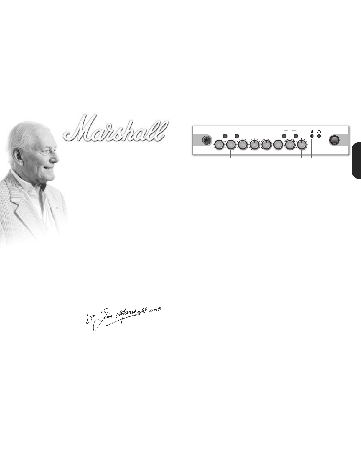
MG15HCFX Front Panel
1. Input Jack Socket
Jack inputfor your guitar. Use a good quality guitar
cable(i.e. one that’s screened/shielded) to help
prevent noise, interference and unwanted feedback.
2. Gain Control
Controls the amount of signal entering the pre-amp
and the amount of distortion createdin the selected
channel.
3. Clean/Crunch Switch
Selects between Clean(green) and Crunch (red)
channels.
4. Bass Control
Turning up the Bass control will add warmth and lowend depth to your sound.
5. OD-1/OD-2 Switch
Selects between OD-1 (green) and OD-2 (red)
channels.
6. Middle Control
Adjusting the middle frequencieswill vary the amount
of body in your sound.
7. Treble Control
Increasing the Treble will make your sounds brighter
and more cutting, turning it down will decrease your
tone’sedge and make it soundsofter as a result.
8. Reverb Control
This control lets you add a lush digital reverb to the
selected channel,from a subtlehint to cavernous
and all points in-between.Furthermore, there are two
distinctly different sounding reverb types for you to
choosefrom – Studioor Spring. Studio emulates the
soundof a studio plate reverbwhile, as expected,
Springemulates the sound of a classic spring reverb
unit.
9. Volume Control
Controls the volume of the selected channel.
10. Tap (Manual)Switch
Matches the delay FX time to the time between two
pushes. The LED flashes at the selected delay time.
Holding down the Tap switch for longer than2
seconds switchesthe amp between manual and
presetmode (pg 2). Whenusing the optional
footcontroller, holding both the Tapswitch and the
Storeswitch will activatethe tuner.
11. FX Control
Selects and adjusts one of five digital effects - Chorus,
Phaser,Flanger, Delay and Octave.
12. Store Switch
Storesthe current amp settingsinto the current
channel or to recallwith the optional footcontroller.
When in manual mode the Store button lights red.
13. MasterControl
Controls the master volumeof the amplifier.
14. MP3 Line In Socket
Jam to your favourite MP3, CD or tape track by
connecting the line out or headphoneoutput of your
playerhere. Adjust the volume of your player to
matchthat of your guitarand you’ve got the perfect
‘play-along’practice system.
15. Headphone Socket
For use when silent practice is the order of the day.
Connection of headphones will automaticallymute
the internal speaker.
16. Power Switch
The power switch turns your amplifieron and off. A
channel switch will light up when your amplifier is
turnedon and none will be lit when the amplifier is
switched off.
Note:The specific mains input voltage rating that your
amplifier has been built for is shown on the back
panel.Before connecting to the mains electricity
supply, always ensurethat your amplifier is
compatible with your electricitysupply. If you have
any doubt,please get advice from a qualified
technician.Your Marshall dealer will help you in this
respect.
Pleaseensure the amplifier is switched off and
unplugged from the mains electricity supply before
beingmoved.
POWER
0 10010 0 10 0 10
0 10
D
E
L
A
Y
C
H
O
R
U
S
F
L
A
N
G
E
R
OD-1/ OD-2CLEAN/CRUNCH
TUNER
STORE
T
AP
(MANUAL)
BASS VOLUMEGAIN
REVERB
TREBLE MASTERFX
P
H
A
S
E
R
OFF OCTAVE
S
T
U
D
I
O
S
P
R
I
N
G
0 10
MIDDLE
INPUT
MG15HCFX
0
0
10
S
T
S
P
R
I
N
G
C
H
S
P
R
I
N
G
R
U
S
F
L
A
N
G
E
R
OFF
OCTAVE
O
0
1 2 4 6 7 8 9 111
3
1
6
3 5 101
2
1
4 15
Page 3

1.FootcontrollerSocket
Jack socketfor the connection of the optional
footcontroller.
2.LoudspeakerOutputs
Connect the two loudspeaker cabinets provided
to the speaker outputs using the speaker leads
supplied.
If you would like to use your MG15HCFX amplifier
head with another speaker system (such as a full
size 4x12" cabinet), ensure that the amplifier is
provided with a total load equal to or greater than
8 ohms.
Always use a non-screened Marshall approved
speaker lead when connecting an extension
cabinet to these units.
32
c
onnection of a pairof headphones. When a jack is
inserted into the headphone socket the unit’s
speaker is muted.
Power
T
he Power switch(17) turns the amplifier on and off. If
current settingshave not beenstored they will be lost.
R
estoring Settings- WARNING ALL AMP &
F
OOTCONTROLLER SETTINGSWILL BE LOST
To restore the unit to factory settings(see handbook
rear cover) you must hold the Store switch (12) while
p
owering on the unit.The Clean/Crunch (3) and OD
(5) lightswill light orange. Youcan then release the
Storeswitch (12).
Resetting the amplifier will erase all user Channel
p
resetsand all user Footcontroller settings, replacing
them with the factory presets.
C
hannelSelection
The amplifier has 4 channels - Clean, Crunch,OD-1 &
OD-2.
Pressing the Clean/Crunch switch(3) selects between
t
he Clean (GreenLight) and Crunch (Red Light)
channels.
P
ressing the OD-1/OD-2 switch (5) selectsbetween the
O
D-1 (Green Light)and OD-2 (Red Light) channels.
When movingfrom an OD channelto a
C
lean/Crunchchannel, the unit remembers the last
channel you were in before leaving.E.g. If you have
movedfrom the Crunch Channel to an OD channel
and you press the Clean/Crunch switch (3), the
amplifier will revertback to the Crunchchannel ratherthan starting againin the Clean channel.
Modes
The amplifier operatesin two modes- Preset and
Manual.
To changebetween these two modes,you musthold
the Tap switch (10) down for at leasttwo seconds.
When in manual mode the Store switch (12) lights red
and the selectedchannel light (3 or 5) willstart to
flash.
The amplifier will remember the last mode it was in
afterpower off and revert to it the next time it is
powered on.
Preset
This is the factory default operation of the amplifier.
In Preset mode the position of all controls except
MasterVolume(13) are stored within each channel.
Each channel should be considered a preset.
Selecting a channel automatically recalls the settings
storedwithin the channel.Note: The physical position
of the front panel controls, exceptMaster Volume (13)
whichis not storable, will now not match the actual
settings of the amplifier. All front panel switches will
automatically update.
Altering a control will cause the associated
parameter to jump to the current physical position of
that control.
When a control is alteredthe selected channellight
(3 or 5) will startto flashindicatingthat the current
presethas been altered.
To storethe updated settings, push the Store switch
(12).
If you select another channel without pressingStore
(12) then any altered settings will be lost as the new
channel and its settings are recalled.
Manual
In manual mode the amp’s settings always match
the physical positionsof the controls.
Changing channelonly changes the channel,NO
presets are recalled,NO othercontrols are altered.
P
ressing Store (12) will store the current settings into
the selected channel.These can then be recalled
when usingthe unit in Presetmode.
W
hen channelsettings have been stored the current
channel light (3 or 5) will stop flashing indicating the
p
resethas been saved.
Reverb& FX
T
he amplifier providestwo simultaneous digital
e
ffects, Reverb (Studioor Spring) and one of five FX
(Chorus, Phaser, Flanger,Delay or Octave)
R
everb
The Reverbcontrol (8) sets the amount of signal sent
to each of the two reverb options - Studio or Spring.
When the Reverbcontrol (8) is set to ‘0’ the reverb is
switched off, the status of the reverb is also indicated
on the optionalfootcontroller.
FX
The FX control is essentially split into fivesegments and
selects the type of FX and adjustsits associated
settings - except in the caseof Octavewhich has a
singlesetting option.When the FX control is set to ‘0’
the FX are switched off, the statusof the FX is also
indicated on the optional footcontroller.
Tap Tempo
The Tap Tempo switch (10) is used for the Delay effect
only.
The Tap Tempo switch matches the delay time to the
time between two presses.
The Tap Tempo LED flashes red at the
selected/recalleddelay time.
The numberof repeats is reduced as the delay time
decreases.
If you change from a channel with delayto one
without delay the effect will spill between channels.
If you change from a channel with delayto a
channel with delay set to a different delay time the
delayeffect will not spill between channels.
MP3 / Line In
The 3.5mm MP3 / Line In socket (14) allows the
connection of an external audio source e.g. MP3 or
CD player.
Headphone Output
The 3.5mm Headphone socket(16) allows the
MG15HCFX Features
0
Chorus
Phaser
Flanger
Delay
Octave
FX Off
Speed increases and depth is reduced as
knob is turned clockwise.
Speed increases as knob is turned
clockwise.
Speed increases, feedback and depth are
reduced as knob is turned clockwise.
Delay level is increased as knob turned
clockwise.
When the FX control is turned fully
clockwise the Octave effect is engaged –
producing a simultaneous note a full octave
lower than the one being played.
ENGLISH
* EUROPE ONLY - Note:
This equipment has been tested and found to comply with the requirements of the EMC Directive
(Environments E1, E2 and E3 EN 55103-1/2) and the Low Voltage Directive in the E.U.
* EUROPE ONLY - Note:
The Peak Inrush current for the MG15HCFX is 2.5 amps.
Note:
Thisequipment has beentested and found to complywith the limits for a Class B digitaldevice, pursuantto part 15 of the FCC rules.
Theselimits are designedto provide reasonable protection against harmful interference in a residential installation.This equipment
generates, usesand can radiate radio frequency energyand, if not installedand used in accordancewith the instructions, may cause
harmfulinterferenceto radio communications.However, there is no guarantee that interference will not occurin a particular installation.If
thisequipment doescause harmful interference to radio or television reception, whichcan be determined by turningthe equipmentoff
and on, the useris encouragedto try to correct the interference by one or more of the followingmeasures:
*
Reorient or relocate the receiving antenna.
*
Increase the separation between the equipment and the receiver.
*
Connect the equipment into an outlet on a circuit different from that to which the receiver is connected.
*
Consult the dealer or an experienced radio/TV technician for help.
Follow all instructions and heed all warnings
KEEP THESE INSTRUCTIONS !
MG15 HCFX Rear Panel
1 2
Page 4

54
Footcontroller (
optional- PEDL-90008)
Footcontroller FactorySettings
Footswitch 1: Clean/Crunch Switch
Footswitch 2: OD-1/OD-2 Switch
Footswitch 3: Tap Tempo Switch
Footswitch 4: Tuner
Programming
The footswitch can be programmed to store front
panelswitches (SwitchStore) or complete presets
(Preset Store).
SwitchStore
To assign a front panel switchto a Footswitch location
(1), pressand hold the frontpanel switch and while
held down pressthe Footswitch(1) you wish to assign
it to.
The DigitalDisplay (3) will swirl to show that the
footswitch has been assigned. Youcan then release
the footswitch and front panel switch.
PresetStore
To assign a preset to a Footswitch (1), select the
required channeland modify the front panel controls
if required, press and hold the Store switch on the
frontpanel and while held down, press your chosen
Footswitch (1).
The DigitalDisplay (3) will swirl to show that the
footswitch has been assigned. Youcan then release
the footswitch and Store switch.
Footcontroller Presetsare independentof the
dedicated Channelpresets storedwithin the
amplifier. This allows you to create a number of
presets based on the same channel/pre-ampsetting.
W
hen eithera Channelpreset or Footswitchpreset
has been altered the Digital Display(3) willbegin to
flash.The footcontroller will flash the relevant number
i
f a Footswitch preset has been altered or will flash a
“-“ if a Channel preset has been altered.
Pressing only the Store switch at this point will
overwrite the alteredChannel or Footswitch preset.
T
o store an altered Channelpreset to the Footswitch
instead, hold the Store switch and while helddown,
pressyour chosen Footswitch (1) - Just like a normal
P
resetStore.
To store an altered Footswitch Presetto another
Footswitch hold the Store switch and while held
down,press your chosen Footswitch (1) - Just like a
normalPreset Store.
Digital Display
When recalling a footswitch preset, the DigitalDisplay
(3) will indicate which footswitch number has been
pressed.
If a Channel preset has been recalled the Digital
Display (3) will remain blank.
When eithera Channel preset or Footswitch preset
has been altered the Digital Display(3) willbegin to
flash.The footswitchwill flash the relevant numberif a
Footswitch preset has been altered or will flash a “-“ if
a Channel preset has been altered.
T
uner
The Tunercan be accessed in two ways:
B
y simultaneouslypushing the Tap (10) and Store (12)
switches on the front panel or by assigning the Tuner
t
o the footswitch. Note: On factory reset/ first switch
on, the Tuneris already assignedto Footswitch
number4.
A
ssigning the Tuner to a footswitchis carried out like
any other Switch Store. To assign the Tuner to the
footswitch hold down the Tap (10) and Store(12)
s
witches and press the chosen footswitch you wish to
assignit to. The DigitalDisplay (3) will swirl to show that
the footswitch has been assigned. You can then
release the footswitch and front panel switches.
For all amplifiers, when entering Tuner mode the unit
mutesand Clean/Crunch (3) and OD-1/OD-2 (5)
switches light yellow.
The DigitalDisplay (3) indicates the closest current
note beingplayed. The indicator dot on the lower
righthand corner shows if the current closestnote
is #.
The LED Status Panel(2) is used to show how far away
from the closest note the current note being played
is. When the centralFX StatusLED lights, it indicates
the correct tuning, with the others progressively
indicating the tuningis up to 50 centsup or down.
To exit the Tunerpush any footswitch, the amplifier will
then exit returning to the settings beforeentering.
1
3 2
1
. Footcontroller
Each footswitch can be assigneda different stored function.
2
. LED Status Panel
This alwaysreflects the current status of the amplifieror tuner details:
CLN & OD: Current Channel
REV: ReverbOn/Off
F
X: FX Section On / Off
E
xt FX: External FX Loop On/Off (MG50CFX & bigger)
Damp:Damping Mode (MG50CFX& bigger)
Tap: TapTempo speed.
3. DigitalDisplay
This display indicatesthe various functions of the footcontroller.
ENGLISH
Page 5

Whilst the information contained herein is correct at the time of publication, due to our policy of constant improvement
and development, Marshall Amplification plc reserve the right to alter specifications without prior notice.
BOOK-91007 / 06 / 11
Marshall Amplification plc
Denbigh Road, Bletchley, Milton Keynes, MK1 1DQ, England.
Tel : +44 (0)1908 375411 Fax : +44 (0)1908 376118
www.marshallamps.com
Clean: Pure guitar tone with a touch of chorus + reverb
green
Crunch: Classic rock tone paired with spring reverb.
OD1: Pure and brutal, with a hint of studio reverb to fatten.
OD2: A soaring arena lead with studio reverb and delay
red
green
red
Marshall Factory Presets
 Loading...