

Page 1

Page 2
POWER
FOOTCONTROLLER
0 10010 0 10 0 10
0 10
D
E
L
A
Y
C
H
O
R
U
S
F
L
A
N
G
E
R
OD-1/ OD-2CLEAN/CRUNCH
TUNER
S
TORE
TAP
(MANUAL)
BASS VOLUMEGAIN
REVERB
TREBLE MASTERFX
P
H
A
S
E
R
OFF OCTAVE
S
T
U
D
I
O
S
P
R
I
N
G
0 10
MIDDLE
INPUT
MG15CFX
0
0
10
S
T
S
P
R
I
N
G
C
H
S
P
R
I
N
G
R
U
S
F
L
A
N
G
E
R
OFF
OCTAVE
O
0
0
10 0 10 0 10 0 10 0 10
BASS VOLUMEGAIN
REVERB
TREBLE MASTERFX
S
T
U
D
I
O
S
P
R
I
N
G
0
10
MIDDLE
TUNER
S
TORE
T
AP
(MANUAL)
OD-1/ OD-2CLEAN/CRUNCH
INPUT POWERFOOTCONTROLLER
MG30CFX
D
E
L
A
Y
C
H
O
R
U
S
F
L
A
N
G
E
R
P
H
A
S
E
R
OFF OCTAVE
0
0
0
0
000
0
S
T
S
P
R
I
N
G
S
0
0
C
H
R
U
S
L
A
N
G
E
R
OFF
OCTAVE
O
0
0
From Jim Marshall
I would personally like to congratulate you on your purchase of this
next-generation Marshall MG amplifier.
As a musician myself, I fullyunderstandwhat it takes to successfully
achieve your goals and dreams. In addition to talent, dedication
and a lot of hard work,you alsoneed equipment that does exactly
what you ask of it. Over the years I have witnessed many advances
in amplifier technology and I wantedthis MG series to take full
advantage of such innovations. To this end, these state-of-the-art
solid-stateamplifiershad to meet the tonal expectationsof the
modernguitarist whilstalso incorporating new and excitingdigital
technology in terms of both effects and memory.With this goal firmly
in mind, I set my experiencedR&D team the task of designing a new
rangeof affordable MG amplifiers that would not only producethe
tone you’re looking for, but also offer an intuitiveand totally
programmableway of customising,storing and accessing your
favourite Marshall tones and features.
Like all the amplifiers in the new MG range,state-of-the-art
manufacturing and stringentquality controlproceduresensure that
theseamplifiersmeet the high standard of build you have come to
expectfrom all Marshall products.
Whether this is your first ever Marshall,or is the latest addition to your
arsenal of amps, the tone, flexibility and feel of these compact,
ruggedunits is guaranteedto deliver the goods – frombedroom to
backstage, from song writing to recordingstudio and from rehearsal
to on stage!
I wish you every success with your new Marshall. Welcome to the
family...
Yours Sincerely,
Dr.Jim Marshall OBE
1
1 2 4 6 7 8 9 11131
5
17
3 5 10121
4
1
6
1 2 4 6 7
8
9 11 13 14 16 15 173 5 10 12
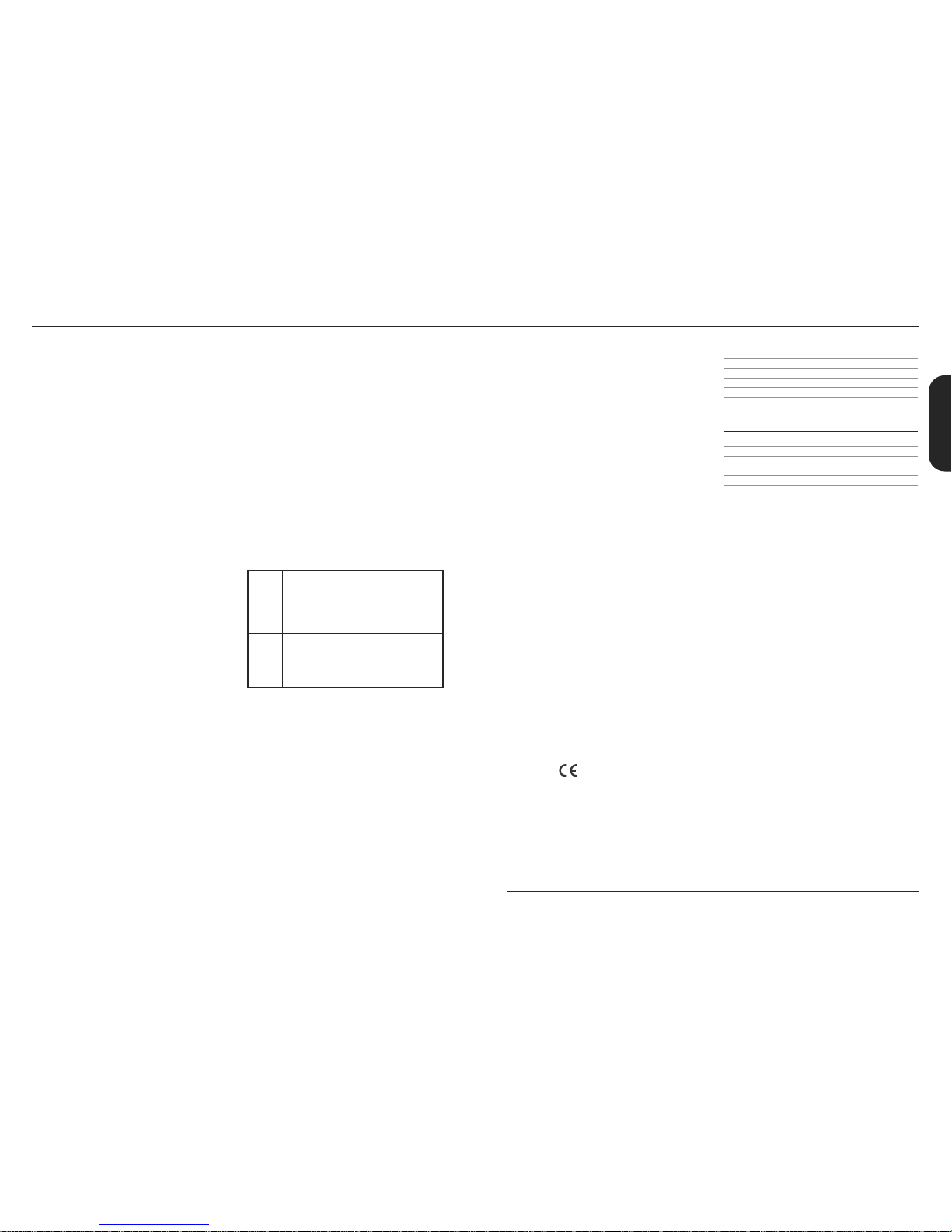
1. Input JackSocket
Jackinputfor your guitar. Use a goodquality guitar cable
(i.e. one that’s screened/shielded)to help prevent noise,
interferenceand unwanted feedback.
2. GainControl
Controlsthe amount of signal enteringthe pre-amp and
theamountof distortioncreated in the selectedchannel.
3. Clean/CrunchSwitch
SelectsbetweenClean(green) and Crunch (red)
channels.
4. BassControl
Turningup the Basscontrolwill addwarmthand low-end
depth to yoursound.
5. OD-1/OD-2 Switch
SelectsbetweenOD-1 (green)and OD-2(red) channels.
6. Middle Control
Adjusting the middle frequencieswill varythe amount of
bodyin your sound.
7. Treble Control
Increasing theTreblewill make yoursoundsbrighter and
morecutting, turningit down willdecrease yourtone’s
edgeand makeit sound softer as a result.
8. Reverb Control
Thiscontrol letsyou add a lushdigitalreverbto the
selectedchannel, from a subtlehint to cavernous and all
points in-between.Furthermore, there are twodistinctly
different soundingreverbtypesfor you to choose from–
Studio or Spring.Studioemulates thesound of a studio
plate reverb while, as expected, Spring emulatesthe
sound of a classic spring reverb unit.
9. Volume Control
Controlsthe volume of theselected channel.
10.Tap (Manual) Switch
Matchesthe delayFX time to the time between two
pushes.The LED flashes at theselected delay time.Holding
downthe Tapswitchfor longer than2 secondsswitches
theamp between manual and presetmode (pg 2).
Whenusingthe optional footcontroller,holdingboth the
Tapswitchand the Store switch willactivate thetuner.
11.FX Control
Selectsand adjusts one of five digital effects- Chorus,
Phaser, Flanger,Delay andOctave.
12.Store Switch
Stores thecurrent amp settingsinto thecurrentchannel or
to recall withthe optionalfootcontroller.When in manual
modethe Storebuttonlights red.
13.MasterControl
Controlsthe master volume of theamplifier.
14.MP3 Line In Socket
Jamto your favouriteMP3, CD ortape trackby
connecting theline out orheadphone output of your
player here. Adjust thevolumeof your player to match
thatof your guitar andyou’vegot the perfect ‘playalong’ practicesystem.
15.FootcontrollerSocket
¼" Jacksocketfor the connectionof the optional
footcontroller (PEDL-90008) - see page8.
16.Headphone Socket
Foruse when silent practice is the order of the day.
Connection of headphoneswill automaticallymute the
internalspeaker.
17.Power Switch
Thepower switch turns youramplifier on andoff. A
channelswitchwill lightup when your amplifieris turned
on andnone willbe lit when theamplifieris switched off.
Note: The specificmainsinput voltageratingthat your
amplifier has beenbuiltfor is shownon the backpanel.
Before connectingto the mainselectricitysupply, always
ensure thatyour amplifier is compatible withyour
electricitysupply.If you haveany doubt, please get
advice froma qualified technician.YourMarshall dealer
willhelp youin this respect.
Please ensure theamplifieris switched off andunplugged
fromthe mainselectricity supply before being moved.
MG30CFX
MG15CFX
ENGLISH
Page 3
32
H
eadphones
The 3.5mm Headphone socket(16) allows the
connection of a pair of headphones.When a jack is
i
nserted into the headphonesocket the unit’s
speaker is muted.
Power
The Power switch (17) turns the amplifieron and off. If
c
urrentsettings have not been storedthey will be lost.
Restoring Settings - WARNING ALL AMP &
FOOTCONTROLLER ALLOCATIONS WILL BE LOST
T
o restore the unit to factorysettings (see handbook
rear cover) you must hold the Store switch (12) while
powering on the unit. The Clean/Crunch (3) and
OD-1/OD-2 (5) lights will lightorange. Youcan then
release the Store switch (12).
Resetting the amplifier will erase all user Channel
presets and all user Footcontroller allocations,
replacing them with the factorypresets.
C
hannelSelection
The amplifier has 4 channels - Clean, Crunch,OD-1 &
OD-2.
Pressing the Clean/Crunch switch(3) selects between
t
he Clean (GreenLight) and Crunch (Red Light)
channels.
P
ressing the OD-1/OD-2switch (5) selects between
t
he OD-1 (Green Light) and OD-2 (Red Light)
channels.
W
hen movingfrom an OD channelto a
Clean/Crunchchannel, the unit remembers the last
channel you were in before leaving.E.g. If you have
movedfrom the Crunch Channel to an OD channel
and you press the Clean/Crunch switch (3), the
amplifier will revertback to the Crunchchannel ratherthan starting againin the Clean channel.
Modes
The amplifier operatesin two modes- Presetand
Manual.
To changebetween these two modes,you musthold
the Tap switch (10) down for at leasttwo seconds.
When in manual mode the Store switch (12) lights red
and the selectedchannel light (3 or 5) willstart to
flash.
The amplifier will remember the last mode it was in
afterpower off and revert to it the next time it is
powered on.
Preset
This is the factory default operation of the amplifier.
In Preset mode the position of all controls except
MasterVolume(13) are stored within each channel.
Each channel should be considered a preset.
Selecting a channel automatically recalls the settings
storedwithin the channel.Note: The physical position
of the front panel controls, exceptMaster Volume (13)
whichis not storable, will now not match the actual
settings of the amplifier. All front panel switches will
automatically update.
Altering a control will cause the associated
parameter to jump to the current physical position of
that control.
When a control is alteredthe selected channellight
(3 or 5) will startto flashindicatingthat the current
presethas been altered.
To storethe updated settings, push the Store switch
(12).
If you select another channel without pressingStore
(12) then any altered settings will be lost as the new
channel and its settings are recalled.
Manual
In manual mode the amp’s settings always match
the physical positionsof the controls.
Changing channelonly changes the channel,NO
presets are recalled,NO othercontrols are altered.
P
ressing Store (12) will store the current settings into
the selected channel.These can then be recalled
when usingthe unit in Presetmode.
When channel settingshave been stored the current
c
hannellight (3 or 5) will stop flashingindicatingthe
presethas been saved.
R
everb& FX
T
he amplifier providestwo simultaneous digital
effects, Reverb (Studio or Spring) and one of five FX
(Chorus, Phaser, Flanger,Delay or Octave)
Reverb
The Reverbcontrol (8) sets the amount of signal sent
to either one of the two reverb options- Studioor
SpringWhen the Reverb control (8) is set to ‘0’ the
reverbis switched off, the status of the reverb is also
indicated on the optional footcontroller.
FX
The FX control is essentially split into fivesegments and
selects the type of FX and adjustsits associated
settings - except in the caseof Octavewhich has a
simplesetting. When the FX control is set to ‘0’ the FX
are switched off, the status of the FX is also indicated
on the optionalfootcontroller.
Tap Tempo
The Tap Tempo switch (10) is used for the Delay effect
only.
The Tap Tempo switch matches the delay time to the
time between two presses.
The Tap Tempo LED flashes red at the
selected/recalleddelay time.
The numberof repeats is reduced as the delay time
decreases.
If you change from a channel with delayto one
without delay the effect will spill between channels.
If you change from a channel with delayto a
channel with delay set to a different delay time the
delayeffect will not spill between channels.
MP3 / Line In
The 3.5mm MP3 / Line In socket (14) allows the
connection of an external audio source e.g. MP3 or
CD player.
MG15CFX & MG30CFX Overview
0
Chorus
Phaser
Flanger
Delay
Octave
FXOff
Speedincreasesanddepthis reducedas
knob is turnedclockwise.
Speedincreasesas knobis turned
clockwise.
Speedincreases, feedbackand depth are
reduced as knob is turnedclockwise.
Delaylevelis increased asknob turned
clockwise.
When theFX controlis turned fully clockwise
theOctave effectis engaged– producing
a simultaneousnotea full octavelowerthan
theone beingplayed.
P
ower (RMS) 15W
C
hannels 4
Speaker 1x8"
Weight (kg) 7.7kg
Size (mm) W, H, D 382 x379 x205
MG15CFXTechnical Specification
P
ower (RMS) 30W
Channels 4
Speaker 1x10"
Weight (kg) 10.8kg
Size (mm) W, H, D 480 x420 x225
MG30CFX TechnicalSpecification
ENGLISH
* EUROPE ONLY - Note:
This equipment has been tested and found to complywith the requirements of the EMC Directive
(Environments E1, E2 and E3 EN5510 3-1/2) and theLow Voltage Directive in the E.U.
* EUROPE ONLY - Note:
The Peak Inrush current for theMG15CFX is 2.5 amps.
The Peak Inrush current for theMG30CFX is 5 amps.
Note:
This equipment has been tested and found to complywith the limits for a Class B digital device, pursuant to part 15 of the
FCC rules. These limits are designedto provide reasonable protection against harmful inter ference in a residential installation. This
equipment generates, uses and can radiate radio frequency energyand, if not installed and used in accordance with the
instructions, may cause harmful inter ference to radiocommunications. However, there is no guarantee that interference will not
occur in a particular installation. If this equipment doescause harmful interference to radio or television reception, which canbe
determined by turning the equipment off and on, the user is encouraged to try to correct the interference by one or more of the
following measures:
*
Reorient or relocate the receiving antenna.
*
Increase the separation between the equipmentand the receiver.
*
Connect the equipment into an outlet on a circuitdifferent from that to which the receiver is connected.
*
Consult the dealer or an experienced radio/TV technician forhelp.
Follow all instructions and heed all warnings
KEEP THESE INSTRUCTIONS !
Page 4

INPUT POWER
0 10
V
OLUME
0 10
G
AIN
0 10
B
ASS
0 10
M
IDDLE
0 10
T
REBLE REVERB
S
T
U
D
I
O
S
P
R
I
N
G
R
E
V
E
R
S
E
H
I
-
F
I
M
U
L
T
I
D
ELAY
T
A
P
E
OFF
0 10
M
ASTER
CLEAN/ CRUNCH
OD-1/ OD-2
T
UNER
S
TORE
DAMPING
(MANUAL)
L
INEOUT
V
I
B
E
C
H
O
R
U
S
F
L
A
N
G
E
R
F
X
P
H
A
S
E
R
OFF OCTAVE
EXT.FXTAP
S
S
P
R
I
N
G
O
R
U
S
F
L
A
N
G
E
R
OFF
OCTAVE
I
F
I
M
U
L
T
I
OFF
54
Rear panel shows MG50CFX combo - MG100CFX combo has the same features
MG100HCFX head is identical except features two loudspeaker sockets
1
21 22 23
24
25 26
2 2
0
3 4 5 6 7 8 9 1011121314151617181
9
1. Input Jack Socket
Jack inputfor your guitar. Use a good quality guitar
cable(i.e. one that’s screened/shielded) to help
prevent noise, interference and unwanted feedback.
2. Gain Control
Controls the amount of signal entering the pre-amp
and the amount of distortion createdin the selected
channel.
3. Clean/Crunch Switch
Selects between Clean(green) and Crunch (red)
channels.
4. Bass Control
Adds warmthand low-end depth to your sound.
5. OD-1/OD-2 Switch
Selects between OD-1 (green) and OD-2 (red)
channels.
6. Middle Control
Varies the amountof body in your sound.
7. Treble Control
Increasing the Treble will make your sounds brighter
and more cutting, turning it down will decrease your
tone’sedge and make it soundsofter as a result.
8. Rev Switch
Switches the reverb effecton and off.
9. Reverb Control
This control lets you add a lush digital reverb to the
selected channel,from a subtlehint to cavernous
and all points in-between.Furthermore, there are two
distinctly different sounding reverb types for you to
choosefrom – Studioor Spring. Studio emulates the
soundof a studio plate reverbwhile, as expected,
Springemulates the sound of a classic spring reverb
unit.
10. VolumeControl
Controls the volume of the selected channel.
11. FX Switch
Switches the FX section (FX and Delay) on and off.
12. FX Control
Selects and adjusts one of five digital effects - Chorus,
Phaser,Flanger, Vibe and Octave.
13. Tap Switch
Matches the delay FX time to the time between two
pushes. The LED flashes at selected delaytime.
14. Delay Control
Controls the amount of signal sent to any one of four
selectable delaytypes – Hi-Fi,Tape, Multi or Reverse.
15. Ext FX Switch
Switches the external FX Loop on and off.
16. MasterControl
Controls the master volumeof the amplifier.
17. Damping(Manual) Switch
Switches the power amp damping between classic
amp feeling(LED off) and modern response (LED on).
Holding down the Damping switchfor longer than 2
seconds switchesthe amp between manual and
presetmode (page 6).
When usingthe footcontroller, holdingboth the
Damping switch and the Store switch will activate the
tuner.
18. Headphone / Line Out Socket
3.5mmheadphones/ Line out.
19. Store Switch
Storesthe current amp settingsinto the current
channel to recall with the footcontroller. When in
manualmode the Store button lights red.
20. Power Switch
The power switch turns your amplifieron and off. A
channel switch will light up when your amplifier is
turnedon and none will be lit when the amplifier is
switched off.
Pleaseensure the amplifier is switched off and
unplugged from the mains electricity supply before
beingmoved.
21. Mains InputConnector
Your amp is provided with a detachable mains
(power) lead, which is connected here. The specific
mainsinput voltage ratingthat your amplifier has
been builtfor is indicated on the back panel. Before
connecting for the first time, please ensure that your
amplifier is compatible with your electricity supply.If
you have any doubt, please get advice from a
qualified technician. Your Marshalldealer will help
you in this respect.
The correct value of mains fuse located in the small
drawerat the bottomof the mains socket is specified
on the rear panel of the amplifier. The drawer
contains a space for a spare fuse.NEVER attempt to
bypassthe fuse or fit one of the incorrect value!
22. Footcontroller Socket
Jack socketfor the connection of the footcontroller.
23. Loudspeaker Output(s) Socket
The MG50CFX, MG101CFXand MG102CFX combos
have 1 loudspeaker output.The MG100HCFX head
has 2 loudspeaker outputs.
Alwaysuse a non-screenedMarshall approved
speaker lead when connecting an extension cabinet
to these amplifiers.
24. MP3 Line In Socket
Jam to your favourite MP3, CD or tape track by
connecting the line out or headphoneoutput of your
playerhere. Adjust the volume of your player to
matchthat of your guitarand you’ve got the perfect
‘play-along’practice system.
25. ReturnSocket
Connect to the output of an external effects
processor or pedal here.
26. Send Socket
Connect to the inputof an externaleffects processor
or pedal here.
Power (RMS) 50W
C
hannels 4
S
peaker 1x12"
W
eight (kg) 16.6kg
S
ize (mm) W, H, D 518 x494 x278
MG50CFX Combo
Power (RMS) 100W
Channels 4
Speaker 1x12"
Weight (kg) 20kg
Size (mm) W, H, D 591 x528 x283
MG101CFX Combo
Power (RMS) 100W
Channels 4
Speaker 2x12"
Weight (kg) 22.4kg
Size (mm) W, H, D 674 x494 x278
MG102CFX Combo
Power (RMS) 100W
Channels 4
Speaker Weight (kg) 11.4kg
Size (mm) W, H, D 591 x249 x275
MG100HCFX Head
Technical Specifications
MG50CFX / MG101CFX / MG102CFX / MG100HCFX
ENGLISH
Page 5

C
hannelSelection
The amplifier has 4 channels - Clean, Crunch,OD1 &
OD2.
Pressing the Clean/Crunch switch(3) selects between
t
he Clean (GreenLight) and Crunch (Red Light)
channels.
P
ressing the OD-1/OD-2switch (5) selects between
t
he OD-1 (Green Light) and OD-2 (Red Light)
channels.
W
hen movingfrom an OD channelto a
Clean/Crunchchannel, the unit remembers the last
channel you were in before leaving.E.g. If you have
movedfrom the Crunch Channel to an OD channel
and you press the Clean/Crunch switch (3), the
amplifier will revertback to the Crunchchannel ratherthan starting againin the Clean channel.
Modes
The amplifier operatesin two modes- Presetand
Manual.
To changebetween these two modes,you musthold
the Dampingswitch (17) down for at least two
seconds. When in manual mode the Store switch(19)
lightsred and the selected channellight (3 or 5) will
startto flash.
The amplifier will remember the last mode it was in
afterpower off and revert to it the next time it is
powered on.
Preset
This is the factory default operation of the amplifier.
In Preset mode the position of all controls except
MasterVolume(16) are stored within each channel.
Each channel should be considered a preset.
Selecting a channel automatically recalls the settings
storedwithin the channel.Note: The physical position
of the front panel controls, exceptMaster Volume (16)
whichis not storable, will now not match the actual
settings of the unit. All front panel switcheswill
automatically update.
Altering a control will cause the associated
parameter to jump to the current physical position of
that control.
When a control is alteredthe selected channellight
(3 or 5) will startto flashindicatingthat the current
presethas been altered.
To storethe updated settings, push the Store switch
(19).
If you select another channel without pressingStore
(19) then any altered settings will be lost as the new
channel and its settings are recalled.
Manual
In manual mode the amps settings always match the
physical positions of the controls.
Changing channelonly changes the channel,NO
presets are recalled,NO othercontrols are altered.
P
ressing Store (19) will store the current settings into
the selected channel.These can then be recalled
when usingthe unit in Presetmode.
When channel settingshave been stored the current
c
hannellight (3 or 5) will stop flashingindicatingthe
presethas been saved.
R
everb,FX & Delay
T
he amplifier providesthree simultaneous digital
effects: Reverb,Delay and any one of the five
offered on the FX control(Chorus, Phaser,Flanger,
V
ibe or Octave).
Reverb
The Reverbcontrol sets the amount of signal sent to
eitherone of the two reverb options - Studio or Spring.
FX
The FX control is essentially split into fivesegments and
selects the type of FX and adjustsits associated
settings – except in the caseof Octavewhich has a
singlesetting. When the FX control is set to ‘0’ the FX
are switched off, the status of the FX is also indicated
on the optionalfootcontroller.
Delay
Hi-Fi A high fidelity, digital delayso pure thateach
individual repeatis identical to the original
note(s)
Tape This emulates the classic,analogue natureof a
tape echo,producing a warm, dark sounding
delayeffect with each successive repeat
diminishing.
Multi A digital delaywith multiple outputs (taps),
each havinga different delaytime.
Reverse As its name suggests, thisemulates the
soundof a reverseor backwards delay –
usually created in a studio by reversingthe
tape or track (i.e.playing it backwards)
Tap Tempo
The Tap Tempo switch (13) is used for the Delay effect
only.
The Tap Tempo switch matches the delay time to the
time between two presses.
The Tap Tempo LED flashes red at the
selected/recalleddelay time.
The numberof repeats is reduced as the delay time
decreases. If you change from a channel with delay
to one without delaythe effect will spill between
channels.
76
I
f you change from a channel with delay to a
channel with delay set to a different delay time the
delayeffect will not spill between channels.
MP3 / Line In
T
he 3.5mm MP3 / Line In socket(24) on the rear panel
allowsthe connectionof an externalaudio source
e.g. MP3 or CD player.
H
eadphones & Line Out
The 3.5mm Headphone socket(18) allows the
connection of a pair of headphones.When a jack is
i
nserted into the headphonesocket the unit’s
speaker is muted.
Additionallythe Headphone socket(18) can also be
used as a Line Out to send the signal to an external
equipment e.g. A computer, digital recorderor mixer.
When a jack is inserted into the socket the unit’s
speaker is muted providing‘silent recording’. The
unit’soutput can then be monitored directly from the
external equipment used.
Damping
The Dampingswitch (17) selectsbetween the two
modesof power amp damping. When Dampingis off
(LED off),the poweramp response resembles the feel
of a classic power amp with emphasized middle and
limited bass and treble. Switching Dampingon (LED
on) will boost the speaker resonances both in the
bass and high frequency ranges.
FX Loop
The FX Return socket (25) on the rear panel is used to
connect the OUTPUT of the effects processor or pedal
you are using in the effects loop.
The FX loop is series and set at instrument levelso both
guitarFX or professional rackeffects units can be
connected.
The FX Send socket (26) on the rear panel is used to
connect to the INPUTof the unit you are using in the
effects loop.
The FX loop is switched on and off via the Ext FX
switch(15) on the frontpanel.
L
oudspeaker
ALWAYS USE A NON-SCREENED MARSHALL APPROVED
SPEAKER LEAD WHEN CONNECTING AN EXTENSION
C
ABINETTO THESEAMPLIFIERS.
M
G50CFX
The singleLoudspeakersocket (22) is used to connect
eitherthe internal speakeror an externalspeaker
c
abinetto the unit’spower amp. When using external
c
abinets ensure the total load impedance is equal to,
or exceeds,8 ohms.
M
G100CFX 1x12" & 2x12" Combos
The singleLoudspeakersocket (22) is used to connect
eitherthe internal speakeror an externalspeaker
cabinet to the unit’s power amp. When using external
cabinets ensure the total load impedance is equal to,
or exceeds,4 ohms.
MG100HCFX Head
The two Loudspeaker sockets are used to connect to
1 or 2 externalcabinets.When using external
cabinets ensure the total load impedance is equal to,
or exceeds,4 ohms.
Power
The Power switch (20) turns the amplifieron and off. If
current settingshave not beenstored they will be lost.
Restoring Settings - WARNING: ALL AMP &
FOOTSWITCH SETTINGS WILL BE LOST
To restore the unit to factory settings(see handbook
rear cover) you must hold the Store switch (19) while
powering on the amplifier. The Clean/Crunch (3) and
OD (5) lights will light orange. You can then release
the Store switch (19).
Resetting the amplifier will erase all user Channel
presets and all user Footcontroller allocations,
replacing them with the factorypresets.
0
Chorus
Phaser
Flanger
Vibe
Octave
FXOff
Speedincreasesanddepthis reducedas
knob is turnedclockwise.
Speedincreasesas knobis turned
clockwise.
Speedincreases, feedbackand depth are
reduced as knob is turnedclockwise.
Thespeedof themodulationincreasesas
thecontrolis turned clockwise.
When theFX control is turned fully clockwise
theOctave effectis engaged– producing
a simultaneousnotea full octavelowerthan
theone beingplayed.
MG50CFX & MG101CFX / MG102CFX / MG100HCFXOverview
* EUROPE ONLY - Note:
This equipment has been tested and found to complywith the requirements of the EMC Directive
(Environments E1, E2 and E3 EN5510 3-1/2) and theLow Voltage Directive in the E.U.
* EUROPE ONLY - Note:
The Peak Inrush current for theMG50CFX is 9.6 amps.
The Peak Inrush current for theMG100HCFX, MG101CFX and MG102CFX is 21 amps.
Note:
This equipment has been tested and found to complywith the limits for a Class B digital device, pursuant to part 15 of the
FCC rules. These limits are designedto provide reasonable protection against harmful inter ference in a residential installation. This
equipment generates, uses and can radiate radio frequency energyand, if not installed and used in accordance with the
instructions, may cause harmful inter ference to radiocommunications. However, there is no guarantee that interference will not
occur in a particular installation. If this equipment doescause harmful interference to radio or television reception, which canbe
determined by turning the equipment off and on, the user is encouraged to try to correct the interference by one or more of the
following measures:
*
Reorient or relocate the receiving antenna.
*
Increase the separation between the equipmentand the receiver.
*
Connect the equipment into an outlet on a circuitdifferent from that to which the receiver is connected.
*
Consult the dealer or an experienced radio/TV technician forhelp.
Follow all instructions and heed all warnings
KEEP THESE INSTRUCTIONS !
ENGLISH
Page 6

98
Footcontroller (
optional- PEDL-90008)
FootcontrollerFactory Settings
Footswitch 1: Clean/Crunch Switch
Footswitch 2: OD-1/OD-2 Switch
Footswitch 3: Tap Tempo Switch
Footswitch 4: Tuner
Programming
The footswitch can be programmed to store front
panel switches (Switch Store) or complete presets
(Preset Store).
SwitchStore
To assign a front panel switch to a Footswitch
location (1), press and hold the front panel switch
and while held down press the Footswitch (1) you
wish to assign it to.
The Digital Display (3) will swirl to show that the
footswitch has been assigned. You can then
release the footswitch and front panel switch.
PresetStore
To assign a preset to a Footswitch (1), select the
required channel and modify the front panel
controls if required, press and hold the Store switch
on the front panel and while held down, press your
chosen Footswitch (1).
The Digital Display (3) will swirl to show that the
footswitch has been assigned. You can then
release the footswitch and Store switch.
Footcontroller Presets are independent of the
dedicated Channel presets stored within the
amplifier. This allows you to create a number of
presets based on the same channel/pre-amp
setting.
W
hen either a Channel preset or Footswitch preset
has been altered the Digital Display (3) will begin
to flash. The footcontroller will flash the relevant
n
umber if a Footswitch preset has been altered or
will flash a “-“ if a Channel preset has been
a
ltered.
Pressing only the Store switch at this point will
o
verwrite the altered Channel or Footswitch
p
reset.
To store an altered Channel preset to the
F
ootswitch instead, hold the Store switch and while
held down, press your chosen Footswitch (1) - Just
like a normal Preset Store.
To store an altered Footswitch Preset to another
Footswitch hold the Store switch and while held down,
press your chosen Footswitch (1) - Just like a nor mal
Preset Store.
Digital Display
When recalling a footswitch preset, the Digital
Display (3) will indicate which footswitch number
has been pressed.
If a Channel preset has been recalled the Digital
Display (3) will remain blank.
When either a Channel preset or Footswitch preset
has been altered the Digital Display (3) will begin
to flash. The footswitch will flash the relevant
number if a Footswitch preset has been altered or
will flash a “-“ if a Channel preset has been
altered.
Tuner
The Tuner can be accessed in two ways:
MG15CFX & MG30CFX
By simultaneously pushing the Tap (10) and Store
(12) switches on the front panel or by assigning the
Tuner to the footswitch. Note: On factory reset /
first switch on, the Tuner is already assigned to
Footswitch number 4.
Assigning the Tuner to a footswitch is carried out
like any other Switch Store. To assign the Tuner to
the footswitch hold down the Tap (10) and Store
(12) switches and press the chosen footswitch you
wish to assign it to. The Digital Display (3) will swirl to
show that the footswitch has been assigned. You
can then release the footswitch and front panel
switch.
M
G50CFX & MG100CFX
By simultaneously pushing the Damping (17) and
Store (19) switches on the front panel or by
a
ssigning the Tuner to the footswitch. Note: On
factory reset / first switch on, the Tuner is already
a
ssigned to Footswitch number 4.
Assigning the Tuner to a footswitch is carried out
l
ike any other Switch Store. To assign the Tuner to
t
he footswitch hold down the Damping (17) and
Store (19) switches and press the chosen footswitch
you wish to assign it to. The Digital Display (3) will
s
wirl to show that the footswitch has been
assigned. You can then release the footswitch and
front panel switches.
For all amplifiers, when entering Tuner mode the
unit mutes and Clean/Crunch (3) and OD-1/OD-2
(5) switches light yellow.
The Digital Display (3) indicates the closest current
note being played. The indicator dot on the lower
right hand corner shows if the current closest note
is #.
The LED Status Panel (2) is used to show how far
away from the closest note the current note being
played is. When the central FX Status LED lights, it
indicates the correct tuning, with the others
progressively indicating the tuning is up to 50 cents
up or down.
To exit the Tuner push any footswitch, the amplifier
will then exit returning to the settings before
entering.
1
3 2
1
. Footcontroller
Each footswitch can be assigned a different stored function.
2
. LEDStatus Panel
This always reflects the current status of the amplifier or tuner details:
CLN & OD: Current Channel
REV: Reverb On/Off
F
X: FX Section On / Off
E
xt FX: External FX Loop On/Off (MG50FX & MG100FX)
Damp: Damping Mode (MG50FX & MG100FX)
Tap: Tap Tempo speed.
3.Digital Display
This display indicates the various functions of the footcontroller.
ENGLISH
Page 7

Whilst the information contained herein is correct at the time of publication, due to our policy of constant improvement
and development, Marshall Amplification plc reserve the right to alter specifications without prior notice.
BOOK-91006 / 06 / 11
Marshall Amplification plc
Denbigh Road, Bletchley, Milton Keynes, MK1 1DQ, England.
Tel : +44 (0)1908 375411 Fax : +44 (0)1908 376118
www.marshallamps.com
Clean: Pure guitar witha touch of chorusand studio reverb - with a subtle delayon the MG50CFX& MG100CFX.
Marshall Factory Presets
Crunch: Classic rock tonepaired with spring reverb. On the MG50CFX & MG100CFX turn the FX on to introduce a slapback delay.
OD1: Pure and brutal, with a hint of studio reverb to fatten. On the MG50CFX & MG100CFX turn theFX on to kick in the Octave effect.
OD2: A soaring arena lead withstudio reverb and delay.
O
n
O
n
Off
On
Off
Off
On
Off
On
On
On
On
 Loading...