

Marshall Amplification MG15CFX, MG30CFX, MG50CFX, MG101CFX, MG102CFX Owner's Manual
...
POWER
FOOTCONTROLLER
0 10010 0 10 0 10
0 10
D
E
L
A
Y
C
H
O
R
U
S
F
L
A
N
G
E
R
OD-1/ OD-2CLEAN/CRUNCH
TUNER
S
TORE
TAP
(MANUAL)
BASS VOLUMEGAIN
REVERB
TREBLE MASTERFX
P
H
A
S
E
R
OFF OCTAVE
S
T
U
D
I
O
S
P
R
I
N
G
0 10
MIDDLE
INPUT
MG15CFX
0
0
10
S
T
S
P
R
I
N
G
C
H
S
P
R
I
N
G
R
U
S
F
L
A
N
G
E
R
OFF
OCTAVE
O
0
0
10 0 10 0 10 0 10 0 10
BASS VOLUMEGAIN
REVERB
TREBLE MASTERFX
S
T
U
D
I
O
S
P
R
I
N
G
0
10
MIDDLE
TUNER
S
TORE
T
AP
(MANUAL)
OD-1/ OD-2CLEAN/CRUNCH
INPUT POWERFOOTCONTROLLER
MG30CFX
D
E
L
A
Y
C
H
O
R
U
S
F
L
A
N
G
E
R
P
H
A
S
E
R
OFF OCTAVE
0
0
0
0
000
0
S
T
S
P
R
I
N
G
S
0
0
C
H
R
U
S
L
A
N
G
E
R
OFF
OCTAVE
O
0
0
From Jim Marshall
I would personally like to congratulate you on your purchase of this
next-generation Marshall MG amplifier.
As a musician myself, I fullyunderstandwhat it takes to successfully
achieve your goals and dreams. In addition to talent, dedication
and a lot of hard work,you alsoneed equipment that does exactly
what you ask of it. Over the years I have witnessed many advances
in amplifier technology and I wantedthis MG series to take full
advantage of such innovations. To this end, these state-of-the-art
solid-stateamplifiershad to meet the tonal expectationsof the
modernguitarist whilstalso incorporating new and excitingdigital
technology in terms of both effects and memory.With this goal firmly
in mind, I set my experiencedR&D team the task of designing a new
rangeof affordable MG amplifiers that would not only producethe
tone you’re looking for, but also offer an intuitiveand totally
programmableway of customising,storing and accessing your
favourite Marshall tones and features.
Like all the amplifiers in the new MG range,state-of-the-art
manufacturing and stringentquality controlproceduresensure that
theseamplifiersmeet the high standard of build you have come to
expectfrom all Marshall products.
Whether this is your first ever Marshall,or is the latest addition to your
arsenal of amps, the tone, flexibility and feel of these compact,
ruggedunits is guaranteedto deliver the goods – frombedroom to
backstage, from song writing to recordingstudio and from rehearsal
to on stage!
I wish you every success with your new Marshall. Welcome to the
family...
Yours Sincerely,
Dr.Jim Marshall OBE
1
1 2 4 6 7 8 9 11131
5
17
3 5 10121
4
1
6
1 2 4 6 7
8
9 11 13 14 16 15 173 5 10 12
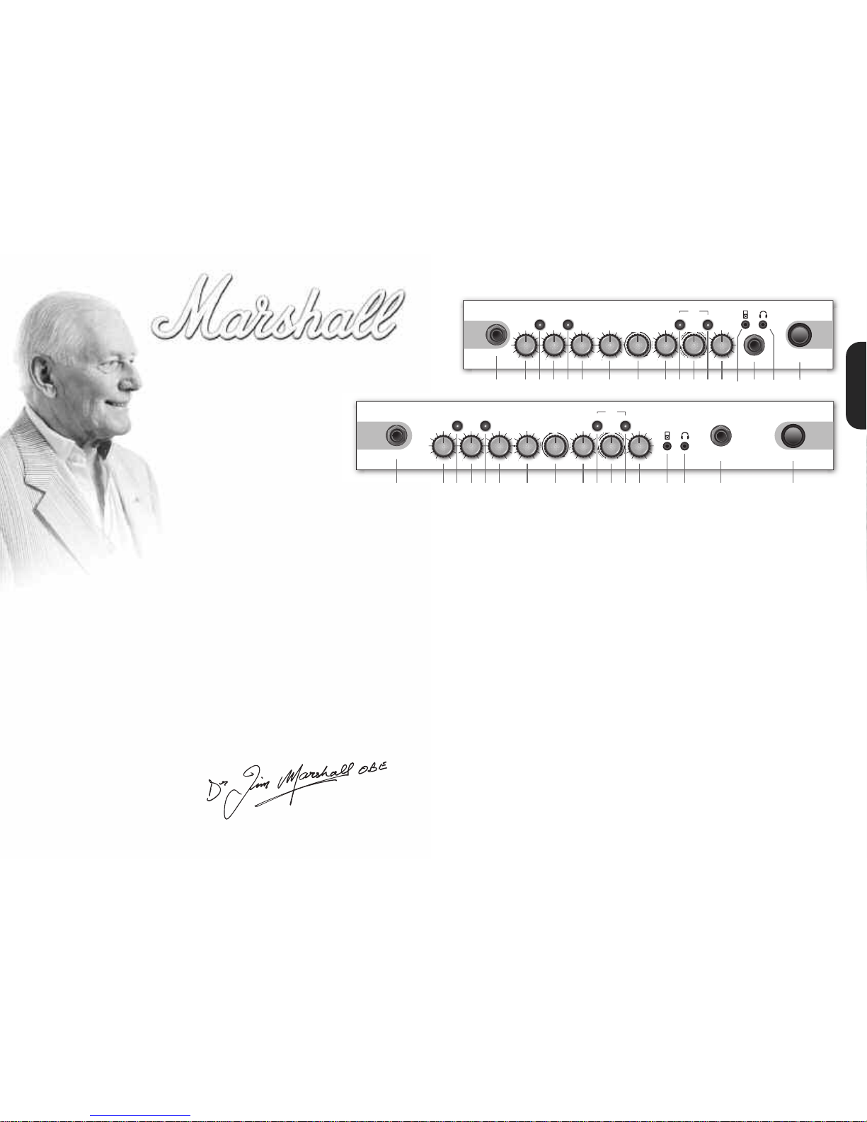
1. Input JackSocket
Jackinputfor your guitar. Use a goodquality guitar cable
(i.e. one that’s screened/shielded)to help prevent noise,
interferenceand unwanted feedback.
2. GainControl
Controlsthe amount of signal enteringthe pre-amp and
theamountof distortioncreated in the selectedchannel.
3. Clean/CrunchSwitch
SelectsbetweenClean(green) and Crunch (red)
channels.
4. BassControl
Turningup the Basscontrolwill addwarmthand low-end
depth to yoursound.
5. OD-1/OD-2 Switch
SelectsbetweenOD-1 (green)and OD-2(red) channels.
6. Middle Control
Adjusting the middle frequencieswill varythe amount of
bodyin your sound.
7. Treble Control
Increasing theTreblewill make yoursoundsbrighter and
morecutting, turningit down willdecrease yourtone’s
edgeand makeit sound softer as a result.
8. Reverb Control
Thiscontrol letsyou add a lushdigitalreverbto the
selectedchannel, from a subtlehint to cavernous and all
points in-between.Furthermore, there are twodistinctly
different soundingreverbtypesfor you to choose from–
Studio or Spring.Studioemulates thesound of a studio
plate reverb while, as expected, Spring emulatesthe
sound of a classic spring reverb unit.
9. Volume Control
Controlsthe volume of theselected channel.
10.Tap (Manual) Switch
Matchesthe delayFX time to the time between two
pushes.The LED flashes at theselected delay time.Holding
downthe Tapswitchfor longer than2 secondsswitches
theamp between manual and presetmode (pg 2).
Whenusingthe optional footcontroller,holdingboth the
Tapswitchand the Store switch willactivate thetuner.
11.FX Control
Selectsand adjusts one of five digital effects- Chorus,
Phaser, Flanger,Delay andOctave.
12.Store Switch
Stores thecurrent amp settingsinto thecurrentchannel or
to recall withthe optionalfootcontroller.When in manual
modethe Storebuttonlights red.
13.MasterControl
Controlsthe master volume of theamplifier.
14.MP3 Line In Socket
Jamto your favouriteMP3, CD ortape trackby
connecting theline out orheadphone output of your
player here. Adjust thevolumeof your player to match
thatof your guitar andyou’vegot the perfect ‘playalong’ practicesystem.
15.FootcontrollerSocket
¼" Jacksocketfor the connectionof the optional
footcontroller (PEDL-90008) - see page8.
16.Headphone Socket
Foruse when silent practice is the order of the day.
Connection of headphoneswill automaticallymute the
internalspeaker.
17.Power Switch
Thepower switch turns youramplifier on andoff. A
channelswitchwill lightup when your amplifieris turned
on andnone willbe lit when theamplifieris switched off.
Note: The specificmainsinput voltageratingthat your
amplifier has beenbuiltfor is shownon the backpanel.
Before connectingto the mainselectricitysupply, always
ensure thatyour amplifier is compatible withyour
electricitysupply.If you haveany doubt, please get
advice froma qualified technician.YourMarshall dealer
willhelp youin this respect.
Please ensure theamplifieris switched off andunplugged
fromthe mainselectricity supply before being moved.
MG30CFX
MG15CFX
ENGLISH
32
H
eadphones
The 3.5mm Headphone socket(16) allows the
connection of a pair of headphones.When a jack is
i
nserted into the headphonesocket the unit’s
speaker is muted.
Power
The Power switch (17) turns the amplifieron and off. If
c
urrentsettings have not been storedthey will be lost.
Restoring Settings - WARNING ALL AMP &
FOOTCONTROLLER ALLOCATIONS WILL BE LOST
T
o restore the unit to factorysettings (see handbook
rear cover) you must hold the Store switch (12) while
powering on the unit. The Clean/Crunch (3) and
OD-1/OD-2 (5) lights will lightorange. Youcan then
release the Store switch (12).
Resetting the amplifier will erase all user Channel
presets and all user Footcontroller allocations,
replacing them with the factorypresets.
C
hannelSelection
The amplifier has 4 channels - Clean, Crunch,OD-1 &
OD-2.
Pressing the Clean/Crunch switch(3) selects between
t
he Clean (GreenLight) and Crunch (Red Light)
channels.
P
ressing the OD-1/OD-2switch (5) selects between
t
he OD-1 (Green Light) and OD-2 (Red Light)
channels.
W
hen movingfrom an OD channelto a
Clean/Crunchchannel, the unit remembers the last
channel you were in before leaving.E.g. If you have
movedfrom the Crunch Channel to an OD channel
and you press the Clean/Crunch switch (3), the
amplifier will revertback to the Crunchchannel ratherthan starting againin the Clean channel.
Modes
The amplifier operatesin two modes- Presetand
Manual.
To changebetween these two modes,you musthold
the Tap switch (10) down for at leasttwo seconds.
When in manual mode the Store switch (12) lights red
and the selectedchannel light (3 or 5) willstart to
flash.
The amplifier will remember the last mode it was in
afterpower off and revert to it the next time it is
powered on.
Preset
This is the factory default operation of the amplifier.
In Preset mode the position of all controls except
MasterVolume(13) are stored within each channel.
Each channel should be considered a preset.
Selecting a channel automatically recalls the settings
storedwithin the channel.Note: The physical position
of the front panel controls, exceptMaster Volume (13)
whichis not storable, will now not match the actual
settings of the amplifier. All front panel switches will
automatically update.
Altering a control will cause the associated
parameter to jump to the current physical position of
that control.
When a control is alteredthe selected channellight
(3 or 5) will startto flashindicatingthat the current
presethas been altered.
To storethe updated settings, push the Store switch
(12).
If you select another channel without pressingStore
(12) then any altered settings will be lost as the new
channel and its settings are recalled.
Manual
In manual mode the amp’s settings always match
the physical positionsof the controls.
Changing channelonly changes the channel,NO
presets are recalled,NO othercontrols are altered.
P
ressing Store (12) will store the current settings into
the selected channel.These can then be recalled
when usingthe unit in Presetmode.
When channel settingshave been stored the current
c
hannellight (3 or 5) will stop flashingindicatingthe
presethas been saved.
R
everb& FX
T
he amplifier providestwo simultaneous digital
effects, Reverb (Studio or Spring) and one of five FX
(Chorus, Phaser, Flanger,Delay or Octave)
Reverb
The Reverbcontrol (8) sets the amount of signal sent
to either one of the two reverb options- Studioor
SpringWhen the Reverb control (8) is set to ‘0’ the
reverbis switched off, the status of the reverb is also
indicated on the optional footcontroller.
FX
The FX control is essentially split into fivesegments and
selects the type of FX and adjustsits associated
settings - except in the caseof Octavewhich has a
simplesetting. When the FX control is set to ‘0’ the FX
are switched off, the status of the FX is also indicated
on the optionalfootcontroller.
Tap Tempo
The Tap Tempo switch (10) is used for the Delay effect
only.
The Tap Tempo switch matches the delay time to the
time between two presses.
The Tap Tempo LED flashes red at the
selected/recalleddelay time.
The numberof repeats is reduced as the delay time
decreases.
If you change from a channel with delayto one
without delay the effect will spill between channels.
If you change from a channel with delayto a
channel with delay set to a different delay time the
delayeffect will not spill between channels.
MP3 / Line In
The 3.5mm MP3 / Line In socket (14) allows the
connection of an external audio source e.g. MP3 or
CD player.
MG15CFX & MG30CFX Overview
0
Chorus
Phaser
Flanger
Delay
Octave
FXOff
Speedincreasesanddepthis reducedas
knob is turnedclockwise.
Speedincreasesas knobis turned
clockwise.
Speedincreases, feedbackand depth are
reduced as knob is turnedclockwise.
Delaylevelis increased asknob turned
clockwise.
When theFX controlis turned fully clockwise
theOctave effectis engaged– producing
a simultaneousnotea full octavelowerthan
theone beingplayed.
P
ower (RMS) 15W
C
hannels 4
Speaker 1x8"
Weight (kg) 7.7kg
Size (mm) W, H, D 382 x379 x205
MG15CFXTechnical Specification
P
ower (RMS) 30W
Channels 4
Speaker 1x10"
Weight (kg) 10.8kg
Size (mm) W, H, D 480 x420 x225
MG30CFX TechnicalSpecification
ENGLISH
* EUROPE ONLY - Note:
This equipment has been tested and found to complywith the requirements of the EMC Directive
(Environments E1, E2 and E3 EN5510 3-1/2) and theLow Voltage Directive in the E.U.
* EUROPE ONLY - Note:
The Peak Inrush current for theMG15CFX is 2.5 amps.
The Peak Inrush current for theMG30CFX is 5 amps.
Note:
This equipment has been tested and found to complywith the limits for a Class B digital device, pursuant to part 15 of the
FCC rules. These limits are designedto provide reasonable protection against harmful inter ference in a residential installation. This
equipment generates, uses and can radiate radio frequency energyand, if not installed and used in accordance with the
instructions, may cause harmful inter ference to radiocommunications. However, there is no guarantee that interference will not
occur in a particular installation. If this equipment doescause harmful interference to radio or television reception, which canbe
determined by turning the equipment off and on, the user is encouraged to try to correct the interference by one or more of the
following measures:
*
Reorient or relocate the receiving antenna.
*
Increase the separation between the equipmentand the receiver.
*
Connect the equipment into an outlet on a circuitdifferent from that to which the receiver is connected.
*
Consult the dealer or an experienced radio/TV technician forhelp.
Follow all instructions and heed all warnings
KEEP THESE INSTRUCTIONS !
 Loading...