

Page 1

Gemini EM/XPS Dual-Scanning Microplate Spectrofluorometer User Guide — 0112-0128 Rev. A
Gemini EM
Gemini XPS
Dual Scanning Microplate
Spectrofluorometer User Guide
Molecular Devices Corporation
1311 Orleans Drive Sunnyvale, California 94089
Part #0112-0128 Rev. A.
Page 2

Gemini EM/XPS Dual-Scanning Microplate Spectrofluorometer User Guide — 0112-0128 Rev. A
Molecular Devices Corporation
Gemini EM/XPS Manual
Copyright
© Copyright 2006, Molecular Devices Corporation. All rights reserved. No part of this publication may
be reproduced, transmitted, transcribed, stored in a retrieval system, or translated into any language or
computer language, in any form or by any means, electronic, mechanical, magnetic, optical, chemical,
manual, or otherwise, without the prior written permission of Molecular Devices Corporation, 1311
Orleans Drive, Sunnyvale, California, 94089, United States of America.
Patents
The Gemini EM, Gemini XPS, and methods have U.S. and International patents pending.
Gemini EM Patents
6,097,025, 6,232,608, 6,236,456, 6,313,471, 6,316,774, and 6,693,709.
Gemini XPS Patents 6,097,025, 6,232,608, 6,236,456, 6,313,471, and 6,316,774.
Trademarks
SpectraPlate and Automix are trademarks and SoftMax are registered trademarks of Molecular Devices
Corporation.
DELFIA is a registered trademark of PerkinElmer Life Sciences.
Emerald II is a trademark of Applera Corp.
All other company and product names are trademarks or registered trademarks of their respective owners.
Disclaimer
Molecular Devices Corporation reserves the right to change its products and services at any time to
incorporate technological developments. This manual is subject to change without notice.
Although this manual has been prepared with every precaution to ensure accuracy, Molecular Devices
Corporation assumes no liability for any errors or omissions, nor for any damages resulting from the
application or use of this information.
Page 3

Gemini EM/XPS Dual-Scanning Microplate Spectrofluorometer User Guide — 0112-0128 Rev. A
Questions?
Phone:1 (800) 6355577
Fax:+1 (408) 7473603
Web:www.moleculardevices.com
Page 4

Gemini EM/XPS Dual-Scanning Microplate Spectrofluorometer User Guide — 0112-0128 Rev. A
Page 5

Gemini EM/XPS Dual Scanning Microplate Spectrofluorometer User Guide — 0112-0128 Rev. A
iii
Contents
Contents
1. Description
Features. . . . . . . . . . . . . . . . . . . . . . . . . . . . . . . . . . . . . . . . . . . . . . . . . . . . . . . . . . . . 1
Components . . . . . . . . . . . . . . . . . . . . . . . . . . . . . . . . . . . . . . . . . . . . . . . . . . . . . . . . 3
2. Principles of Operation
Fluorescence . . . . . . . . . . . . . . . . . . . . . . . . . . . . . . . . . . . . . . . . . . . . . . . . . . . . . . . . 9
TimeResolved Fluorescence . . . . . . . . . . . . . . . . . . . . . . . . . . . . . . . . . . . . . . . . . . . 11
Luminescence . . . . . . . . . . . . . . . . . . . . . . . . . . . . . . . . . . . . . . . . . . . . . . . . . . . . . . 11
Functional Description . . . . . . . . . . . . . . . . . . . . . . . . . . . . . . . . . . . . . . . . . . . . . . . 12
3. Installation
Unpacking. . . . . . . . . . . . . . . . . . . . . . . . . . . . . . . . . . . . . . . . . . . . . . . . . . . . . . . . . 15
Setting up the Instrument . . . . . . . . . . . . . . . . . . . . . . . . . . . . . . . . . . . . . . . . . . . . . 15
Installing the Drawer Adapter . . . . . . . . . . . . . . . . . . . . . . . . . . . . . . . . . . . . . . . . . . 16
Removing the Drawer Adapter . . . . . . . . . . . . . . . . . . . . . . . . . . . . . . . . . . . . . . . . . 17
4. Operation
Quick Overview . . . . . . . . . . . . . . . . . . . . . . . . . . . . . . . . . . . . . . . . . . . . . . . . . . . . 19
Preparing for a Reading . . . . . . . . . . . . . . . . . . . . . . . . . . . . . . . . . . . . . . . . . . . . . . . 19
Read the Microplate . . . . . . . . . . . . . . . . . . . . . . . . . . . . . . . . . . . . . . . . . . . . . . . . . 20
Optimizing Asays . . . . . . . . . . . . . . . . . . . . . . . . . . . . . . . . . . . . . . . . . . . . . . . . . . . 21
5. Maintenance
Technical Support . . . . . . . . . . . . . . . . . . . . . . . . . . . . . . . . . . . . . . . . . . . . . . . . . . . 27
Moving the Gemini. . . . . . . . . . . . . . . . . . . . . . . . . . . . . . . . . . . . . . . . . . . . . . . . . . 27
Cleaning . . . . . . . . . . . . . . . . . . . . . . . . . . . . . . . . . . . . . . . . . . . . . . . . . . . . . . . . . . 28
Cleaning the Fan Filter . . . . . . . . . . . . . . . . . . . . . . . . . . . . . . . . . . . . . . . . . . . . . . . 28
Changing the Fuses . . . . . . . . . . . . . . . . . . . . . . . . . . . . . . . . . . . . . . . . . . . . . . . . . . 29
Page 6

Contents
Gemini EM/XPS Dual Scanning Microplate Spectrofluorometer User Guide — 0112-0128 Rev. A
iv
Contents
6. Troubleshooting
Opening the Drawer Manually . . . . . . . . . . . . . . . . . . . . . . . . . . . . . . . . . . . . . . . . . 33
Error Codes and Probable Causes . . . . . . . . . . . . . . . . . . . . . . . . . . . . . . . . . . . . . . . 33
7. Specifications
Gemini EM Specifications. . . . . . . . . . . . . . . . . . . . . . . . . . . . . . . . . . . . . . . . . . . . . 41
Geminie XPS Specifications . . . . . . . . . . . . . . . . . . . . . . . . . . . . . . . . . . . . . . . . . . . 43
A. Appendix
Cables . . . . . . . . . . . . . . . . . . . . . . . . . . . . . . . . . . . . . . . . . . . . . . . . . . . . . . . . . . . . 43
Accessories. . . . . . . . . . . . . . . . . . . . . . . . . . . . . . . . . . . . . . . . . . . . . . . . . . . . . . . . . 44
B. Appendix
Common Wavelengths for Fluorescence and Luminescence . . . . . . . . . . . . . . . . . . . 45
Glossary . . . . . . . . . . . . . . . . . . . . . . . . . . . . . . . . . . . . . . . . . . . . . . . . . . . . . . . . . . 46
System Diagrams and Dimensions . . . . . . . . . . . . . . . . . . . . . . . . . . . . . . . . . . . . . . 49
Page 7

Gemini EM/XPS Dual Scanning Microplate Spectrofluorometer User Guide — 0112-0128 Rev. A
1
1. Description
1. Description
1.1. FEATURES
The Gemini EM and Gemini XPS DualScanning Microplate Spectrofluorometers can
perform a variety of fluorescent applications. The extreme flexibility and high sensitivity
of Gemini readers make them appropriate for applications within the fields of
biochemistry, cell biology, immunology, molecular biology, and microbiology.
1.1.1. DUAL MONOCHROMATORS
The right pair of excitation and emission wavelengths is always available because the dual
monochromators allow the selection of any wavelength in 1 nm increments. New
fluorophores can easily be evaluated without purchasing additional filters.
The Gemini EM and Gemini XPS microplate readers use two holographic diffraction
grating monochromators, which allow for individual optimization of wavelengths for
both excitation and emission. The dualscanning capability can also be used to determine
excitation and emission settings for new fluorescent probes.
1.1.2. OPTICS
Mirrored optics focus the light into the sample volume, and cutoff filters are used to
reduce stray light and minimize background interference. The light source is a high
powered Xenon flash lamp; additional flexibility is provided by allowing a variable
number of lamp flashes per read.
1.1.3. WAVELENGTH SCANNING
The most sensitive results are achieved by using optimal excitation and emission
wavelengths. Literature wavelengths are often based on results from wavelengthlimited,
filterbased readers. Wavelength scanning ensures that the most sensitive assay conditions
are used.
1.1.4. WELL SCANNING
Gemini EM and Gemini XPS can report a single point from the well center, or multiple
data points from the bottom of large well tissue culture plates to provide high sensitivity
for cellbased assays.
1.1.5. AUTO PMT GAIN
Because a single microplate often presents a range of fluorescence intensities greater than
three orders of magnitude, Gemini EM and Gemini XPS feature “Auto PMT Gain” to
Page 8

1. Description
Gemini EM/XPS Dual Scanning Microplate Spectrofluorometer User Guide — 0112-0128 Rev. A
2
1. Description
avoid saturating the photomultiplier tube. The signal is calibrated against an internal
standard, so the reported RFU values of individual samples can be accurately compared.
1.1.6. TOP AND BOTTOM READING OPTICS—GEMINI EM ONLY
The top/bottomreading optical design of the Gemini EM allows for measurements for
both solution and cellbased assays. With the click of a button, the Gemini EM can be
switched between top and bottomreading modes.
1.1.7. SUPPORTED PLATES
Microplates having 6, 12, 24, 48, 96, and 384 wells can be used in Gemini readers.
One plate carrier adapter is provided with the instrument. The adapter is required for
optimum performance with standard 96 and 384well format microplates when reading
from the top of the microplate.
1.1.8. DYNAMIC RANGE
The dynamic range of detection is from 10–6 to 10
–11
molar fluorescein. Variations in
measured fluorescence values are virtually eliminated by internal compensation for
detector sensitivity, photomultiplier tube voltage and sensitivity, as well as excitation
intensity.
1.1.9. TEMPERATURE CONTROL
Temperature in the microplate chamber is isothermal, both at ambient and when the
incubator is turned on. When the incubator is on, the temperature may be controlled
from 4°C above ambient to 45°C.
1.1.10. AUTOMIX
The contents of the wells in a microplate can be mixed automatically by shaking before
each read cycle, which makes it possible to perform kinetic analysis of solidphase,
enzymemediated reactions such as a kinetic ELISA.
1.1.11. COMPUTER CONTROL
Gemini readers are controlled by an external computer running SoftMax® Pro software
which provides integrated instrument control, data display, and statistical data analysis.
Gemini readers cannot be operated without the computer and SoftMax Pro software.
1.1.12. SECONDARY MODES
The Gemini EM and Gemini XPS have two secondary modes that can be used for limited
development of glow luminescence or timeresolved fluorescence assays. The performance
of these two modes is not comparable to dedicated luminescence or timeresolved
fluorescence instruments.
Page 9

1.2. Components
Gemini EM/XPS Dual Scanning Microplate Spectrofluorometer User Guide — 0112-0128 Rev. A
3
1. Description
Figure 1.1: Gemini EM.
1.2. COMPONENTS
The main components of Gemini readers described in this manual are:
>
Control panel
>
Microplate drawer
>
Optical system
>
Back panel (connections and power switch)
1.2.1. THE CONTROL PANEL
The control panel consists of a 2×20character LCD and four pressuresensitive
membrane keys that can be used to initiate and regulate the temperature and to open and
close the drawer. When you press a control panel key, the Gemini performs the associated
action.
Figure 1.2: Control Panel.
Page 10

1. Description
Gemini EM/XPS Dual Scanning Microplate Spectrofluorometer User Guide — 0112-0128 Rev. A
4
1. Description
TEMP
The keys allow you to enter a set point at which to regulate the microplate
chamber temperature.
Pressing this key scrolls the temperature up or down, starting at the previous temperature
setting (or the default of 37.0°C, if no setting had been made):
>
Pressing the up (S) or down (T) arrow once increments or decrements the displayed
temperature by 0.1°C.
>
Pressing and holding either arrow increments or decrements the displayed temperature
by 1°C until it is released.
You cannot set a temperature beyond the upper (45°C) or lower (15°C) instrument limits.
Tem p O n/ Of f
The key enables and disables the incubator.
>
When the incubator is on, the set temperature and actual temperature are shown on the
front panel LCD display.
>
When the instrument is performing a kinetic or spectral scan, the temperature keys on
the front panel are disabled.
Drawer
The key opens and closes the microplate drawer.
1.2.2. THE MICROPLATE DRAWER
The microplate drawer, located on the right side of the Gemini, slides in and out of the
microplate chamber. A small plastic pusher, located in the front left corner of the drawer,
holds the plate securely in place when the drawer is closed. The drawer remains in the
reading chamber during read cycles.
One plate carrier adapter is provided with the instrument. The adapter is required for
optimum performance with standard 96well and 384well format microplates in top read
mode. The adapter is required when using the SpectraTest FL validation plate to test the
Gemini XPS and when testing the Gemini EM top read optics. To test the Gemini EM
bottom reading performance, remove the purple adapter and then turn the validation
plate upside down by rotating it from toptobottom so that column 1 remains on your
left.
TEMP
TEMP on/off
DRAWER
Page 11

1.2. Components
Gemini EM/XPS Dual Scanning Microplate Spectrofluorometer User Guide — 0112-0128 Rev. A
5
1. Description
Figure 1.3: Microplate drawer (with adapter inserted).
The adapter must be removed to read 6well, 12well, 24well, or 48well plates.
Microplate drawer operation varies, depending on the incubator setting:
>
If the incubator is off, the drawer remains open.
>
If the incubator is on, the drawer closes after approximately 10 seconds to assist in
maintaining temperature control within the microplate chamber.
To add reagents during a kinetic read, it is necessary to open the drawer by pressing the
key. The drawer only opens, however, if the interval between readings is equal
to the minimum read interval originally shown by SoftMax Pro software plus an
additional 45 seconds. If you plan to open the drawer during a kinetic read, first
determine the minimum read interval allowed and then increase the setting by a
minimum of 45 seconds. The drawer closes automatically after this interval before the
next read.
Do not obstruct the movement of the drawer. If you must retrieve a plate after an error
condition or power outage and the drawer does not open, it is possible to open it
manually (see Chapter 6, “Troubleshooting”).
1.2.3. MICROPLATES
Gemini readers can accommodate standard 6well, 12well, 24well, 48well, 96well, and
384well microplates. Blackwalled, clearbottom or allblack microplates are generally
recommended for fluorescence assays because they have lower backgrounds than clear
plates. White plates may be preferred for luminescence assays to optimize light collection.
Not all manufacturers’ microplates are the same with regard to design, materials, or
configuration. Some plastics, most notably polystyrene, also have significant native
fluorescence and can cause moderate to severe background fluorescence, especially in the
UV range. If high sensitivity is required, it may be appropriate to use microplates that are
designed to reduce background fluorescence.
DRAWER
Page 12

1. Description
Gemini EM/XPS Dual Scanning Microplate Spectrofluorometer User Guide — 0112-0128 Rev. A
6
1. Description
1.2.4. THE OPTICAL SYSTEM—GEMINI EM
Figure 1.4: Components of the Gemini EM optical system.
1 The excitation light source is a xenon flash lamp. (Note that the lamp is off when
luminescence mode is selected.)
2 The light passes through a bandpass filter that reduces the amount of stray light to the
excitation monochromator.
3 The holographic diffraction grating monochromator selects the desired excitation
wavelength.
4 The excitation beam is focused by a grating to a 1.0mm diameter fiber into the upper
or lower optics read head (selectable) before entering the sample in the microplate well.
This focusing helps to prevent part of the beam from striking adjacent wells.
5 The light beam enters the well and, if fluorescent molecules are present, light of the
emission wavelength is emitted back out to mirrors that focus it and send it to an
optical bundle.
6 The emission monochromator (also a holographic diffraction grating monochromator)
allows light of the chosen emission wavelength to pass to the emission filter wheel.
7 A longpass filter further conditions the light prior to detection by the photomultiplier
tube (PMT). This filter may be set automatically by the instrument or manually by the
user.
8 The PMT detects the emitted light and passes a quantitative signal to the instrument’s
electronics that then send the data to the computer.
movable
grating
flash lamp
1 mm
fiber
4 mm
optical
bundles
microplate
movable,
focusing
grating
photomultiplie
tube
1
2
3
4
5
6
7
8
Ex
cutoff
filter
wheel
Em
cutoff
filter
wheel
Page 13

1.2. Components
Gemini EM/XPS Dual Scanning Microplate Spectrofluorometer User Guide — 0112-0128 Rev. A
7
1. Description
1.2.5. THE OPTICAL SYSTEM—GEMINI XPS
Figure 1.5: Components of the Gemini XPS optical system.
1 The excitation light source is a xenon flash lamp. (Note that the lamp is off when
luminescence mode is selected.)
2 The light passes through a bandpass filter that reduces the amount of stray light to the
excitation monochromator.
3 The holographic diffraction grating monochromator selects the desired excitation
wavelength.
4 The excitation beam is collimated by a mirror to a 1.0mm diameter fiber before
entering the sample in the microplate well. This focusing helps to prevent part of the
beam from striking adjacent wells.
movable
grating
flash lamp
1-mm
fiber
4-mm
optical
bundles
microplate
Excitation monochromator
Emission monochromator
Reading chamber
single channel upper
optics on linear stage
movable,
focusing
grating
photomultiplier
tube
1
2
3
4
5
6
7
8
Ex
cutoff
wheel
Em
cutoff
wheel
Page 14

1. Description
Gemini EM/XPS Dual Scanning Microplate Spectrofluorometer User Guide — 0112-0128 Rev. A
8
1. Description
5 The light beam enters the well and, if fluorescent molecules are present, light of the
emission wavelength is emitted back out to mirrors that focus it and send it to an
optical bundle.
6 The emission monochromator (also a holographic diffraction grating monochromator)
allows light of the chosen emission wavelength to pass to the emission filter wheel.
7 A longpass filter further conditions the light prior to detection by the photomultiplier
tube (PMT). This filter may be set automatically by the instrument or manually by the
user.
8 The PMT detects the emitted light and passes a quantitative signal to the instrument’s
electronics which then send the data to the computer.
1.2.6. THE BACK PANEL
Figure 1.6: Schematic of the back panel of a Gemini reader.
The following components are located on the back panel of Gemini readers:
>
Power switc h: a rocker switch, labeled I/O (for on and off, respectively).
>
Power cord receptacle: plug the power cord in here.
>
Fuse box cover: cannot be opened while the power cord is plugged in. When opened, it
provides access to the fuse box containing two fuses that are required for operation.
>
Parallel port: present but not used in this model of reader.
>
Serial port (doubleshielded RS232, for use with an external computer): plug one end
of an 8pin DIN serial cable into this port; the other end attaches to the serial (modem)
port of the computer.
>
Label: provides information about the Gemini, such as line voltage rating, cautionary
information, serial number, etc. Record the serial number shown on this label for use
when contacting Molecular Devices Technical Support.
RS-232
Serial
Parallel Port
Power Switch
Fuse Box Cover
Power Cord
Receptacle
Label
Page 15

Gemini EM/XPS Dual Scanning Microplate Spectrofluorometer User Guide — 0112-0128 Rev. A
9
2. Principles of Operation
2. Principles of Operation
2.1. FLUORESCENCE
Fluorescent materials absorb light energy of a characteristic wavelength (excitation),
undergo an electronic state change, and instantaneously emit light of a longer wavelength
(emission). Most common fluorescent materials have wellcharacterized excitation and
emission spectra. Figure 2.1 shows an example of excitation and emission spectra for a
fluorophore. The excitation and emission bands are each fairly broad, with half
bandwidths of approximately 40 nm, and the wavelength difference between the
excitation and emission maxima (the Stokes shift) is typically fairly small, about 30 nm.
There is considerable overlap between the excitation and emission spectra (gray area)
when a small Stokes shift is present.
Figure 2.1: Excitation and emission spectra.
Excitation
maxim um
Emission
maxim um
Stokes
shift
1.0
0.5
0
Relative Fluorescence
Wavelength (nm)
500 550 600 650
Page 16

2. Principles of Operation
Gemini EM/XPS Dual Scanning Microplate Spectrofluorometer User Guide — 0112-0128 Rev. A
10
2. Principles of Operation
Because the intensity of the excitation light is usually many tens of thousands of times
greater than that of the emitted light, some type of spectral separation is necessary to
reduce the interference of the excitation light with detection of the emitted light. The
Gemini readers incorporate many features designed to restrict interference from reflected
excitation light. Among these features is a set of longpass emission cutoff filters that can
be set automatically by the instrument or manually by the user. If the Stokes shift is small,
it may be advisable to choose an excitation wavelength that is as far away from the
emission maximum as possible while still being capable of stimulating the fluorophore so
that less of the excited light overlaps the emission spectrum, allowing better selection and
quantitation of the emitted light.
Figure 2.2: Optimized excitation and emission reading wavelengths.
Figure 2.2 shows that the best results are often obtained when the excitation and emission
wavelengths used for reading are not the same as the wavelengths of the excitation and
emission spectra of the fluorophore. When the reading wavelengths for excitation and
emission are separated, a smaller amount of excitation light passes through to the emission
monochromator (gray area) and on to the PMT, resulting in a purer emission signal and
more accurate data.
The Gemini readers allow scanning of both excitation and emission wavelengths, using
separate tunable monochromators. One benefit of being able to scan emission spectra is
Excitation
reading
Emission
reading
Fluorophore’s
excitation
1.0
0.5
0
Relative Fluorescence
Wavelength (nm)
500 550 600 650
maximum
Fluorophore’s
emission
maximum
wavelength
wavelength
Page 17

2.2. Time-Resolved Fluorescence
Gemini EM/XPS Dual Scanning Microplate Spectrofluorometer User Guide — 0112-0128 Rev. A
11
2. Principles of Operation
that you can assess more accurately whether the emission is, in fact, the expected
fluorophore, or multiple fluorophores, and not one generated by a variety of background
sources or by contaminants. Another benefit is that you may be able to find excitation and
emission wavelengths that avoid interference when interfering fluorescent species are
present.
For this reason, it may be desirable to scan emission for both an intermediate
concentration of labeled sample, as well as the background of unlabeled sample. The
optimum setting is where the ratio of the sample emission to background emission is at
the maximum.
For more information regarding optimizing excitation and emission wavelengths using
the spectral scanning capabilities of the Gemini, see “Optimizing Assays ” on page 21.
2.2. TIME-RESOLVED FLUORESCENCE
In normal fluorescence mode, readings are taken while the lamp is on. The most common
limitation to sensitivity in normal fluorescence is excitation energy or background
fluorescence that cannot be eliminated from the emission signal. Since the lamp is the
source of excitation energy, turning it off provides the best means of eliminating
background excitation.
Timeresolved fluorescence is performed by flashing the excitation lamp and, after it is off,
collecting the delayed emission for a period of time before the lamp is flashed again.
Lanthanide dyes are frequently used to delay the fluorescence long enough to measure it
after the lamp is turned off.
To assist with proper collection of data, you can also select when to start and end data
collection (within the limits of the system—the minimum is 50 μs and the maximum is
1450 μs in 200μs steps).
2.3. LUMINESCENCE
In luminescence mode, no excitation is necessary as the species being measured emit light
naturally. For this reason, the lamp does not flash, so no background interference occurs.
A dark estimate is done over a dark reference, and multiple readings are averaged together
into one reading per well.
You can choose the wavelength where peak emission is expected to occur. In addition,
multiple wavelength choices allow species with multiple components to be differentiated
and measured easily. In luminescence read mode, no emission cutoff filter is used. The
default setting for luminescence is the “zero order” position where the grating
monochromator acts as a mirror that reflects all light to the PMT detector.
The Gemini readers are microplate spectrofluorometers with photomultiplier tube
detection. Some luminescence applications, such as gene reporter assays, may require a
luminometer with photon counting detection for greater sensitivity.
Page 18

2. Principles of Operation
Gemini EM/XPS Dual Scanning Microplate Spectrofluorometer User Guide — 0112-0128 Rev. A
12
2. Principles of Operation
2.4. FUNCTIONAL DESCRIPTION
The Gemini readers are designed to be operated using SoftMax Pro software running on a
computer connected to the instrument. Standalone functions are limited to setting and
enabling temperature control and opening or closing the microplate drawer.
The information contained in this section provides an overview of the instrument
capabilities. For a complete description of the modes of operation, how to choose
instrument settings, etc., refer to the SoftMax Pro User’s Manual.
2.4.1. READ MODES
The Gemini EM and Gemini XPS can read in three modes: fluorescence, secondary
luminescence, and secondary time resolved fluorescence.
2.4.2. READ TYPES
Within each read mode, Gemini readers can perform four types of read: endpoint, kinetic,
spectrum, and well scan. Instrument setup parameters for each read type are discussed in
the SoftMax Pro User’s Manual.
Endpoint Read
In an Endpoint read, a reading of each microplate well is taken at a single or multiple
wavelengths.
Depending on the read type selected, values can be reported as relative fluorescence units
(RFU) or relative luminescence units (RLU).
Kinetic Read
In a Kinetic read the data are collected over time with multiple readings taken at regular
intervals. To achieve the shortest possible interval for Kinetic readings, choose
wavelengths in ascending order.
Kinetic analysis can be performed for up to 99 hours. The kinetic read interval depends
upon the instrument setup parameters chosen in SoftMax Pro.
Kinetic analysis has many advantages when determining the relative activity of an enzyme
in different types of microplate assays, including ELISAs and the purification and
characterization of enzymes and enzyme conjugates. Kinetic analysis is capable of
providing improved dynamic range, precision, and sensitivity relative to endpoint
analysis.
Spectrum Read
Spectral analysis measures fluorescence or luminescence across a spectrum of wavelengths.
The Gemini EM reader allows excitation and emission wavelength scanning from 250 nm
to 850 nm. The Gemini XPS reader allows excitation scanning from 250 nm to 850 nm
and emission scanning from 360 nm to 850 nm.
Page 19

2.4. Functional Description
Gemini EM/XPS Dual Scanning Microplate Spectrofluorometer User Guide — 0112-0128 Rev. A
13
2. Principles of Operation
When reading using fluorescence, you can set a fixed wavelength for excitation and scan
the emission wavelengths, or vice versa. The default value reported for each well is the
wavelength of maximum fluorescence.
When luminescence is chosen, only the emission wavelengths are scanned, and the default
value reported for each well is the wavelength of maximum luminescence.
All spectrum readings are made using the scanning monochromators of the Gemini
reader.
Well Scan Read
Some applications that involve the detection of whole cells in largearea tissue culture
plates may require the use of well scanning mode. As many cell lines tend to grow in
clumps or in the corner of microplate wells, this nonconfluent growth pattern may
require multiple reads in a well at different locations.
When used with 6well, 12well, 24well, 48well, or 96well plates, well scanning allows
maximum surface area detection for whole cell assays. No plate adapter is required when
using largearea tissue culture plates.
For more information on well scanning, please review the appropriate section in the
SoftMax Pro User’s Manual.
2.4.3. TEMPERATURE REGULATION
The Gemini readers have been designed to regulate the temperature of the microplate
chamber from 4°C above ambient to 45°C. Upon power up, when the incubator is off,
the temperature in the Gemini microplate chamber is ambient and isothermal. Turning
on the incubator by pressing the key causes the Gemini to begin warming
the microplate chamber. The temperature set point defaults to 37.0°C at startup.
Accuracy of the temperature set point is guaranteed only if the set point is at least 4°C
above ambient. If the temperature set point is lower than the ambient temperature, the
chamber temperature remains at ambient. Temperature regulation is controlled by heaters
only and, therefore, cannot cool the temperature to a setting lower than ambient.
Additionally, the highest setting (45°C) can be achieved only if the ambient temperature
is greater than 20°C.
Typically, the microplate chamber reaches 37.0°C in less than 30 minutes. The microplate
chamber temperature is maintained at the set point until you press the incubator
key again, turning temperature regulation off.
Should you turn the incubator back on after a momentary shutdown, allow about ten
minutes for the control algorithm to fully stabilize the microplate chamber temperature.
Temperature regulation and control of the microplate chamber is achieved through
electric heaters, a fan, efficient insulation, and temperature sensors. The heaters are
TEMP on/off
TEMP on/off
Page 20

2. Principles of Operation
Gemini EM/XPS Dual Scanning Microplate Spectrofluorometer User Guide — 0112-0128 Rev. A
14
2. Principles of Operation
located in the microplate chamber, which is insulated to maintain the temperature set
point. The sensors are mounted inside the chamber and measure the air temperature.
The temperature feedback closedloop control algorithms measure the chamber air
temperature, compare it to the temperature set point, and use the difference to calculate
the regulation of the heating cycles. This technique results in accurate, precise control of
the chamber temperature with a temperature variation of the air inside the chamber of less
than 1.0°C. The temperature uniformity within the microplate depends on its design and
composition.
2.4.4. AUTOMIX
The Automix function permits automatic shaking of the microplate at preset intervals,
thereby mixing of the contents within each well. Automix must be selected before
beginning a reading. The actions associated with the Automix setting depend on the read
mode chosen:
>
Endpoint mode: Automix shakes the plate for a definable number of seconds and then
reads at all selected wavelengths.
>
Kinetic mode: two types of Automix can be enabled: Automix can shake the plate for a
definable number of seconds before the initial reading, and/or for a definable number of
seconds before each subsequent reading.
>
Use of Automix is strongly recommended for ELISAs and other solidphase, enzyme
mediated reactions to enhance accuracy.
2.4.5. COMPUTER CONTROL
The Gemini is equipped with an 8pin DIN RS232 serial port through which the
computer communicates with the instrument. (Different types of cables are available for
connecting to different types of computers—see Appendix A, “Cables” and “Accessories”.)
Page 21

Gemini EM/XPS Dual Scanning Mocroplate Spectrofluorometer User Guide — 0112-0128 Rev. A
15
3. Installation
3. Installation
ãWARNING: Always make sure the power switch on the instrument is in the OFF
position and remove the power cord from the back of the instrument prior to any
installation or relocation of the instrument.
ãWARNING: Do not operate the instrument in an environment where potentially
damaging liquids or gases are present.
ãCAUTION: Do not touch or loosen any screws or parts other than those specifically
designated in the instructions. Doing so might cause misalignment and voids the
instrument warranty.
3.1. UNPACKING
The Gemini is packed in a specially designed carton. Please retain the carton and the
packing materials. If the unit should need to be returned for repair, you must use the
original packing materials and carton for shipping. If the carton has been damaged in
transit, it is particularly important that you retain it for inspection by the carrier in case
there has also been damage to the instrument.
ãWARNING: The Gemini weighs approximately 35 pounds (16 kg) and should be lifted
with care. It is recommended that two persons lift the instrument together, taking the
proper precautions to avoid injury.
After examining the carton, place it on a flat surface in the upright position. Open the top
of the box and lift the Gemini, along with the packing materials around the ends, up and
out of the shipping box. Remove the packing material from both ends of the instrument
and set the instrument down carefully. The packing list that accompanies the instrument
describes all components that should have been placed in the packing carton. Make sure
all these items are present before proceeding.
3.2. SETTING UP THE INSTRUMENT
1 Place the Gemini on a level surface, away from direct sunlight, dust, drafts, vibration,
and moisture.
2 Turn the instrument around so that the back of the instrument is facing you as shown
in Figure 1.6.
3 Insert the female end of the power cord into the power receptacle at the rear of the
Gemini. Connect the male end to a grounded power outlet of the appropriate voltage.
Page 22

3. Installation
Gemini EM/XPS Dual Scanning Mocroplate Spectrofluorometer User Guide — 0112-0128 Rev. A
16
3. Installation
Molecular Devices recommends that you use a surge protector between the power cord
and the grounded power outlet.
4 Insert the 8pin DIN round end of the computer connection cord into the RS232
serial port receptacle on the back panel of the instrument. Attach the other end to your
computer (see Appendix A for more information).
5 Turn the Gemini around so that the control panel now faces you. Ensure no cables run
beneath the instrument. Leave at least three inches between the back of the instrument
and the nearest objects or surfaces to ensure proper ventilation and cooling.
3.3. INSTALLING THE DRAWER ADAPTER
ãCAUTION: Incorrect insertion or removal of the adapter may cause damage to the
microplate drawer of the Gemini. The corner cutout must be in the lower left corner
where the plate pusher is located.
If you are reading standard 96well or 384well microplates from the top, you need to
install the drawer adapter.
1 Power on the instrument using the switch on the back panel.
2 Press the DRAWER button on the front panel or activate the drawer open command in
SoftMax Pro software.
3 Hold the adapter so that the label is on the front side facing up.
4 Place the top back (Row A) portion of the adapter into the drawer first. The corner
cutout must be in the lower left corner where the plate pusher is located. While
pushing against the back edge of the adapter, lower the front of the adapter into the
drawer.
Figure 3.1: Adapter inserted in microplate drawer.
Page 23

3.4. Removing the Drawer Adapter
Gemini EM/XPS Dual Scanning Mocroplate Spectrofluorometer User Guide — 0112-0128 Rev. A
17
3. Installation
3.4. REMOVING THE DRAWER ADAPTER
If the adapter is in the drawer and you are either reading from the bottom(Gemini EM
only) or using “high profile” (6well, 12well, 24well, or 48well) plates, you need to
remove the adapter.
Incorrect insertion or removal of the adapter may cause damage to the microplate drawer
of the Gemini.
1 Power on the instrument using the switch on the back panel.
2 Press the button on the front panel or activate the drawer open command
in SoftMax Pro software.
3 Remove the adapter plate.
Figure 3.2: Microplate drawer without adapter.
DRAWER
Page 24

3. Installation
Gemini EM/XPS Dual Scanning Mocroplate Spectrofluorometer User Guide — 0112-0128 Rev. A
18
3. Installation
Page 25

Gemini EM/XPS Dual Scanning Microplate Spectrofluorometer User Guide — 0112-0128 Rev. A
19
4. Operation
4. Operation
This chapter contains operating information for the Gemini DualScanning Microplate
Spectrofluorometer.
4.1. QUICK OVERVIEW
If you are an experienced user of this instrument, the following steps provide a quick
reminder of the basic operating procedures required to perform an assay using the
Gemini:
1 Turn on the power switch of the Gemini (located on the back panel). The microplate
drawer opens automatically.
2 If you want to regulate the temperature inside the microplate chamber, touch the
(incubator) key to turn the incubator on and bring the microplate
chamber to the default temperature of 37.0°C. The microplate drawer closes.
3 If the incubator is on, the LCD shows the current temperature along with the
temperature set point. To change the set point (to any setting from ambient +4° to
45°C), press the up or down arrow keys.
4 Select the desired instrument settings (read mode, type of analysis, template, etc.) using
SoftMax Pro software on the external computer.
5 If you are performing kinetic analysis, add substrate at this time.
6 Load the prepared microplate into the drawer, being sure to match well A1 with the A1
mark on upper lefthand corner of the drawer.
7 Using SoftMax Pro, start the reading.
4.2. PREPARING FOR A READING
4.2.1. TURN THE INSTRUMENT AND COMPUTER ON
The power switch for the Gemini is located on the back panel. Press the rocker switch to
the
ON position.
The instrument automatically performs diagnostic checks to ensure that it is functioning
correctly. Turn the computer on at this time also and start the SoftMax Pro software
program.
TEMP on/off
Page 26

4. Operation
Gemini EM/XPS Dual Scanning Microplate Spectrofluorometer User Guide — 0112-0128 Rev. A
20
4. Operation
4.2.2. SET THE TEMPERATURE (OPTIONAL)
To set the temperature within the microplate chamber, you should turn on the incubator
first, allowing enough time for the temperature to reach the set point before performing a
reading. When you first turn the instrument on, up to 60 minutes may be required for the
temperature within the chamber to reach the set point. Turning on the incubator and
choosing a temperature set point can be done using the software or the front panel of the
instrument (described here).
Temperature cannot be regulated at a set point that is lower than 4°C above the ambient
temperature.
To enable the incubator:
1 Press the incubator key.
2 The LCD display indicates that temperature control is on and shows the set point and
current temperature of the microplate chamber.
To change the temperature set point:
1 Press the up or down arrow keys until the desired temperature set point is shown in the
display.
The microplate chamber temperature is maintained at the set point until you disable
temperature control by touching the incubator key again. When the incubator is off, the
temperature within the microplate chamber gradually returns to ambient.
Should you turn the incubator back on after a momentary shutdown, allow about ten
minutes for the control algorithm to fully stabilize the microplate chamber temperature.
4.3. READ THE MICROPLATE
ãBIOHAZARD: The underside of the microplate must be dry prior to placing it in the
drawer. If the microplate has fluid on the underside, dry it using a paper towel (or
equivalent) before placing it in the drawer.
1 Insert the filled microplate into the drawer, matching well A1 with position A1 in the
drawer. Make sure the microplate is flat against the drawer bottom (for 6, 12, 24, or
48well microplates) or against the adapter (if using top read for 96 or 386well
plates—see “Installing the Drawer Adapter” for more information).
2 You must have SoftMax Pro software running on a computer connected to the Gemini.
Press the button in SoftMax Pro to start the plate read.
3 When reading is complete, the drawer of the instrument opens, allowing you to
remove the microplate. If the incubator is on, the drawer closes again after
approximately 10 seconds.
4 If you return to the Gemini and find the drawer closed after a reading has finished,
press the key. When the drawer opens, you can remove the microplate.
TEMP on/off
READ
DRAWER
Page 27

4.4. Optimizing Assays
Gemini EM/XPS Dual Scanning Microplate Spectrofluorometer User Guide — 0112-0128 Rev. A
21
4. Operation
4.4. OPTIMIZING ASSAYS
4.4.1. INTRODUCTION
The optimum instrument settings for detection of a particular fluorophore depend on a
number of different factors. Settings that can be adjusted for assay optimization include
the excitation and emission wavelengths, emission cutoff filter, readings per well, the
PMT voltage, the temperature of the reading chamber, and the length of delay time for
timeresolved fluorescence.
Another important factor that is independent of the instrument but which affect assays
optimization is the Stokes shift. When the Stokes’ shift is very small, optimizing the
excitation and emission wavelengths and correct cutoff filter choices are very important.
Excitation and Emission Wavelengths
The excitation and emission wavelengths may be set in 1nm increments within the range
of the instrument. The Gemini EM reader allows excitation and emission wavelength
scanning from 250 nm to 850 nm. The Gemini XPS reader allows excitation scanning
from 250 nm to 850 nm and emission scanning from 360 nm to 850 nm. A procedure to
optimize excitation and emission wavelengths for a given assay is outlined in the next
section.
Emission Cutoff Filter
The 15 emission cutoff filters assist in reducing background. Sources of background
include stray excitation light and native fluorescence of plate materials, sample
constituents, and solvents (including water). The default setting allows the instrument
and SoftMax Pro software to determine which cutoff filter should be used (see
Table 4.1for default settings) in endpoint and kinetic modes. The spectral scan mode
default uses no cutoff filter.
Readings per well
The number of readings per well may vary between 1 (used for a quick estimate) and 30
(for very precise measurements). The default number of readings per well varies with the
read mode: for fluorescence, the default is 6, and for luminescence, the default is 30.
PMT Voltage
The voltage of the photomultiplier tube may be set to low (for higher concentration
samples), medium, or high (for lower concentration samples) in all read modes. In
endpoint and spectrum mode, there is an additional setting, automatic, in which the
instrument automatically adjusts the PMT voltage for varying concentrations of sample in
the plate.
Temperature control
The chamber of the Gemini is isothermal at ambient as well as at elevated temperatures.
The temperature in the reading chamber may be adjusted from 4°C above ambient to
45°C.
Page 28

4. Operation
Gemini EM/XPS Dual Scanning Microplate Spectrofluorometer User Guide — 0112-0128 Rev. A
22
4. Operation
Delay Time
In timeresolved fluorescence mode, you may set the integration start and end time in
200μsecond increments from the minimum 50 μs to the maximum 1450 μs.
4.4.2. USING SPECTRAL SCANNING TO OPTIMIZE EXCITATION AND EMISSION
WAVELENGTHS FOR FLUORESCENCE ASSAYS
Put 200 μL of sample that includes the fluorophore and 200 μL of a buffer control into
separate wells of a microplate.
1 Excitation Scan
a Using SoftMax Pro, set up a Plate section for a fluorescence read, spectrum mode,
Em Fixed/Ex Scan, with no cutoff filter (default), and medium PMT.
b Set the emission wavelength based on the tentative value from the literature (or from
a customary filter set used to measure your fluorophore). If the emission wavelength
is not known, select a tentative emission wavelength about 50 nanometers greater
than the absorbance maximum of the fluorophore. If necessary, the absorbance
maximum can be determined by performing a spectral scan in a UV/Vis
spectrophotometer.
c Set the excitation scan to start/stop approximately 50 nm below/above the tentative
excitation value obtained from the literature (or the customary excitation filter).
d Set the step increment to 1 or 2 nm. (You may choose to do a preliminary scan with
a 10nm increment to determine the approximate peak location, and then repeat the
scan over a narrower wavelength range with a 1 or 2nm increment.)
e Perform the scan and view the results as a plot of emission fluorescence vs. excitation
wavelength. Note the excitation wavelength at the emission peak and the maximum
RFU value.
If an error message reporting missing data points occurs, it may be due to possible
saturation reported by SoftMax Pro at the end of the spectral scan. Reset the PMT to
“low” and rescan the sample (scan the buffer blank with the PMT set to “medium”
or “high”). If the error occurs after scanning with the PMT set to “low,” it may be
necessary to dilute the sample.
If the excitation scan shows no apparent peak, change the PMT setting to “high” and
rescan the sample. If the spectral scan still shows no apparent peak, adjust the Yscale
of the zoom plot so that the plot fills the graph.
f Select the optimal excitation wavelength. If the excitation peak wavelength and
emission wavelength are separated by more than 80 nm, use the excitation peak
wavelength value. If the excitation and emission wavelengths are less than 80 nm
apart, use the shortest excitation wavelength that gives 90% maximal emission.
(Follow the plot to the left of the peak until the RFU value falls to approximately
90% of the maximum, and then drop a line from the 90% point on the plot to the
xaxis—see Figure 4.1)
Page 29

4.4. Optimizing Assays
Gemini EM/XPS Dual Scanning Microplate Spectrofluorometer User Guide — 0112-0128 Rev. A
23
4. Operation
Figure 4.1: Figure 4.1: Plot of RFU vs. Wavelength.
2 Emission Scan #1
a In SoftMax Pro, set up a second plate section for a fluorescence read, spectrum
mode, Ex Fixed/Em Scan, with no cutoff filter (default), and medium PMT.
b Set the excitation wavelength to the value determined in 2F above.
c Set the emission scan to start/stop approximately 50 nm below or above the tentative
emission value obtained from the literature (or existing filter pair). Note: If the
Stokes shift is less than 50 nm, then start the emission scan above the excitation
wavelength.
d Set the step increment to 12 nm (or do a preliminary scan with a 10nm increment
to determine the approximate peak location and then repeat the scan over a narrower
wavelength range using a 12 nm increment.)
e Perform the scan and view the results as a plot of fluorescence vs. emission
wavelength.
3 Emission Filter
a Select an emission cutoff filter that blocks as much of the residual excitation light as
possible without unduly reducing the fluorescence signal. The cutoff wavelength
choices are 325(Gemini EM only), 420, 435, 475, 495, 515, 530, 550, 570, 590,
610, 630, 665, or 695 nm. The cutoff value should be near the maximum emission
wavelength (preferably between the excitation wavelength and the maximal emission
wavelength) but at least 35 nm greater than the excitation wavelength.
4 Emission Scan #2
a In SoftMax Pro, set up a third plate section for an emission scan as specified in Step
3 above, except selecting Manual Cutoff Filter and setting the wavelength to that
determined in Step 4.
b Perform the scan and view the results as a plot of fluorescence vs. emission
wavelength. Note the wavelength giving the maximum emission (the optimal
emission wavelength).
Page 30
4. Operation
Gemini EM/XPS Dual Scanning Microplate Spectrofluorometer User Guide — 0112-0128 Rev. A
24
4. Operation
c Compare the spectra of the sample containing the fluorophore to the spectra of the
buffer blank to get an estimate of the signaltonoise ratio. If there is significant
background interference, repeat steps 5A and 5B with another choice of cutoff filter.
5 Results
The optimal excitation and emission wavelengths are those determined in steps 1f and 4b,
above.
6 Comments
a In endpoint or kinetic fluorescence modes, the “Autofilter” feature generally selects
the same cutoff filter wavelength as the above optimization method. If desired,
however, you may specify the cutoff filters manually.
b For emission wavelengths less than 325 nanometers, experimental iteration is usually
the best method of determining the optimal emission and excitation wavelengths.
Begin optimization by performing steps 1–4 above. Try emission and excitation
wavelength combinations with the 325 cutoff or with no cutoff filter. Similarly, for
excitation wavelengths greater than 660 nanometers, try emission and excitation
wavelength combinations with the 695 cutoff or with no cutoff filter.
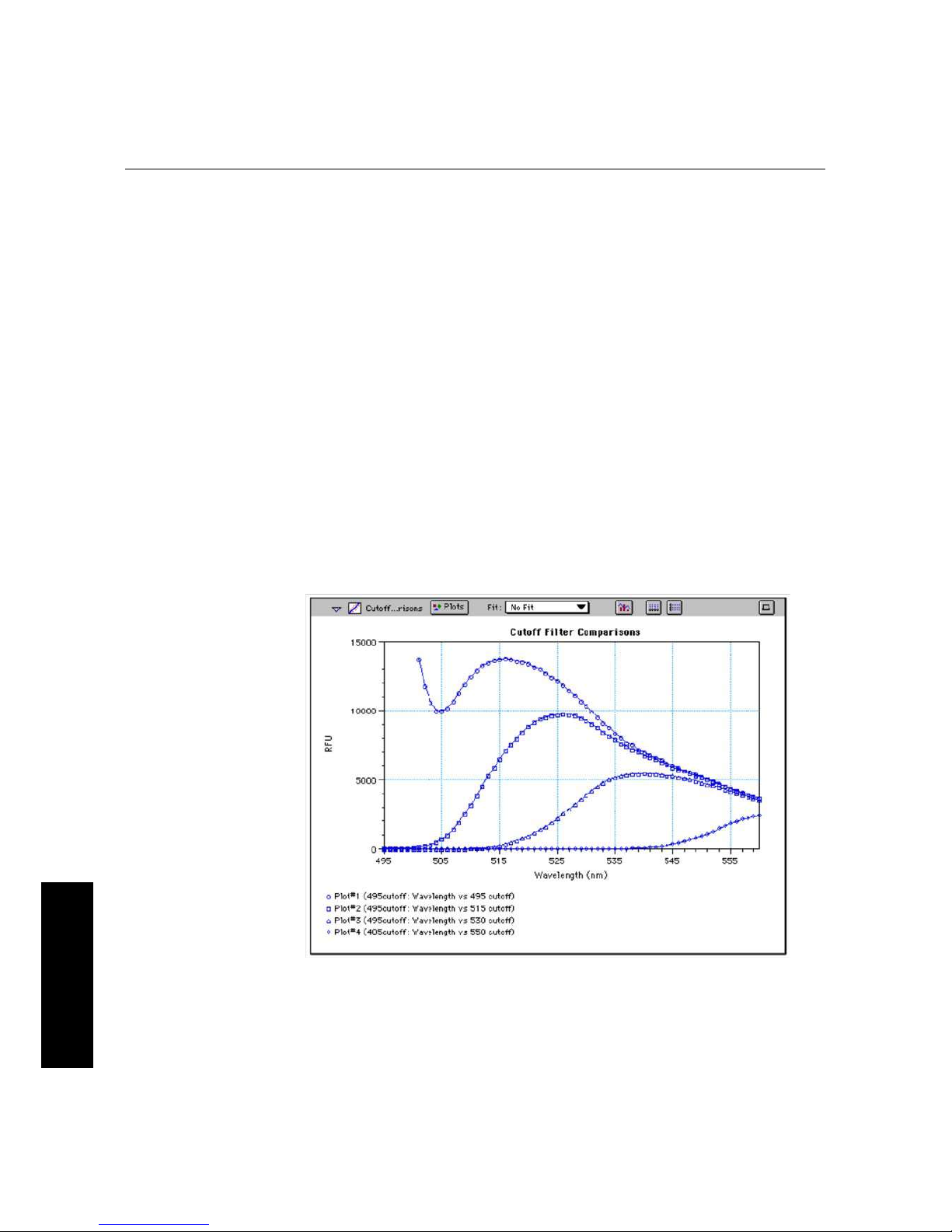
Figure 4.2: Effects of Cutoff Filters on Fluorescein. Emission was scanned from 490 to 560 nm;
excitation was fixed at 485 nm.
Figure 4.2 shows the effects of different cutoff filters on a scan of fluorescein where
excitation was fixed at 485 nm and emission was scanned from 490 nm to 560 nm (buffer
Page 31

4.4. Optimizing Assays
Gemini EM/XPS Dual Scanning Microplate Spectrofluorometer User Guide — 0112-0128 Rev. A
25
4. Operation
blanks are not shown in this plot). Table 4.1 following lists default settings for the
emission cutoff filters.
Table 4.1: Gemini XPS Emission Cutoff Filter Default Setting.
For spectrum mode, the default is "manual" (no automatic cutoff).
Automatic Cutoff Selection Endpoint and Kinetic Modes
#
Wavelength (nm) Emission Wavelength (nm)
1 None < 415
2 420 415–434
3 435 435–454
4 455 455–474
5 475 475–494
6 495 495–514
7 515 515–529
8 530 530–549
9 550 550–569
10 570 570–589
11 590 590–609
12 610 610–629
13 630 630–664
14 665 665–694
15 695 695–850
Page 32

4. Operation
Gemini EM/XPS Dual Scanning Microplate Spectrofluorometer User Guide — 0112-0128 Rev. A
26
4. Operation
Page 33

Gemini EM/XPS Dual Scanning Microplate Spectrofluorometer User Guide — 0112-0128 Rev. A
27
5. Maintenance
5. Maintenance
5.1. TECHNICAL SUPPORT
Molecular Devices Corporation is a leading worldwide manufacturer and distributor of
analytical instrumentation. We are committed to the quality of our products and to fully
supporting our customers with the highest possible level of technical service. In order to
fully benefit from our technical services, please complete the registration card and return
it to the address printed on the card.
If you have any problems using the Gemini EM or XPS DualScanning Microplate
Spectrophotometer, in the U.S., contact our Technical Services group at 18006355577;
elsewhere contact your local representative.
ãWARNING: All maintenance procedures described in this manual can be safely
performed by qualified personnel. Maintenance not covered in this manual should be
performed only by a Molecular Devices representative.
ãWARNING: Turn the power switch off and disconnect the power cord from the main
power source before performing any maintenance procedure that requires removal of any
panel or cover or disassembly of any interior instrument component.
ãWARNING: Removal of protective covers that are marked with the High Voltage
warning symbol shown below can result in a safety hazard.
5.2. MOVING THE GEMINI
If you need to relocate the Gemini, follow these steps.
The Gemini weighs approximately 35 pounds (16 kilograms). To avoid injury, it is
recommended that two people lift the instrument together, using proper lifting
techniques.
1 Remove any microplate (and the adapter, if any) from the drawer and then close the
drawer. Leaving the adapter in the drawer when moving the Gemini could cause
damage to the instrument.
Page 34

5. Maintenance
Gemini EM/XPS Dual Scanning Microplate Spectrofluorometer User Guide — 0112-0128 Rev. A
28
5. Maintenance
2 Turn off the power switch and unplug the power cord from the source and from the
receptacle on the back of the instrument.
3 Depending on the distance that you are moving the instrument, you may want to
repackage the Gemini in its original shipping carton. Otherwise, carry the instrument
or place it on a rolling cart to transport it.
4 Ensure that the new location meets the proper specifications as described in Chapter 3,
“Setting Up the Instrument”.
5.3. CLEANING
ãBIOHAZARD: Wear gloves during any cleaning procedure that could involve contact
with either hazardous or biohazardous materials or fluids.
ãWARNING: Never clean the inside of the instrument.
Periodically, you should clean the outside surfaces of the Gemini using a cloth or sponge
that has been dampened with water:
>
Do not use abrasive cleaners.
>
If required, clean the surfaces using a mild soap solution diluted with water or a glass
cleaner and then wipe with a damp cloth or sponge to remove any residue.
>
Do not spray cleaner directly onto the instrument.
If needed, clean the microplate drawer using a cloth or sponge that has been dampened
with water.
Should fluids spill in the drawer area (when the drawer is out), they are directed to a tray
at the bottom of the instrument, from which they exit to the bench or counter beneath
the instrument. Wipe up any spills immediately.
Do not allow excess water or other fluids to drip inside the instrument.
5.4. CLEANING THE FAN FILTER
The fan filter on the bottom of the instrument requires periodic cleaning. The frequency
of cleaning depends on how dusty your particular lab is and could range from once a
month to once every six months.
1 Turn power to the instrument OFF and then remove the power cord and cables from
the back of the instrument.
2 Remove any plate or adapter from the instrument drawer. Turn the instrument over so
that it rests flat on the bench.
3 Pop the black fan cover off and remove the filter.
Page 35

5.5. Changing the Fuses
Gemini EM/XPS Dual Scanning Microplate Spectrofluorometer User Guide — 0112-0128 Rev. A
29
5. Maintenance
4 Clean the filter by blowing clean, canned air through it or by rinsing it—first with
water and then with alcohol—and allowing it to dry completely.
5 Place the clean, dry filter over the fan and replace the black cover.
6 Turn the instrument back over. Reconnect the power cord and cables to the
instrument.
5.5. CHANGING THE FUSES
Fuses burn out occasionally and must be replaced.
If the instrument does not seem to be getting power after switching it on (the LCD shows
no display):
1 Check to see whether the power cord is securely plugged in to a functioning power
outlet and to the receptacle at the rear of the Gemini.
If power failed while the Gemini was already on:
1 Check that the power cord is not loose or disconnected and that power to the power
outlet is functioning properly.
If these checks fail to remedy the loss of power, follow the steps listed below to replace the
fuses. Spare fuses (two U.S. and two metric) are shipped with the instrument. The U.S.
and metric fuses are identical except for physical size. They may be taped to the back of
the Gemini.
If you no longer have spare fuses, you may obtain new ones from Molecular Devices (part
numbers: 46010013 for U.S., 46010014 for metric) or from a local hardware store.
Make sure fuses are rated SLOWBLOW (U.S.: 4amp timedelay; metric: 4amp,
5 × 20 mm, timedelay).
To change fuses:
1 Switch power to the instrument off and then remove the power cord from the outlet
and from the Gemini power cord receptacle.
2 Remove the computer cable from the back of the Gemini.
3 Turn the instrument around for easy access to the rear panel.
4 On the lefthand side of the rear panel (viewed from the back) is the power switch, fuse
box, and power cord receptacle. As shown in the figures below, press to the left of the
black plastic cover of the fuse box to release it. Pull the fuse box cover away from the
instrument. The fuse box will begin to slide forward.
Page 36

5. Maintenance
Gemini EM/XPS Dual Scanning Microplate Spectrofluorometer User Guide — 0112-0128 Rev. A
30
5. Maintenance
Figure 5.1: Power switch, fuse box, and power receptacle.
5 Continue gently pulling the fuse box forward until it is free of the instrument.
Figure 5.2: Removing the fuse box.
6 When removed, the fuse assembly will appear as shown in Figure 5.3. The holder
inside contains two fuses.
Page 37

5.5. Changing the Fuses
Gemini EM/XPS Dual Scanning Microplate Spectrofluorometer User Guide — 0112-0128 Rev. A
31
5. Maintenance
Figure 5.3: The fuse box and holder (with fuses) removed from instrument.
7 It is possible that only one of the fuses may have blown. However, Molecular Devices
recommends that you replace both fuses to ensure continued proper operation. Pull
both fuses out of the holder and discard them.
8 Insert new SLOWBLOWrated fuses into the fuse holder. Either end of the fuse may
be forward.
9 Insert the fuse box into the opening in the instrument, making sure that the fuses are
on the left side (toward the power receptacle). Press the fuse box into place, making
sure the cover snaps closed.
10 Reconnect the power cord to the instrument and to the wall outlet and reconnect other
cables previously disconnected.
Page 38

5. Maintenance
Gemini EM/XPS Dual Scanning Microplate Spectrofluorometer User Guide — 0112-0128 Rev. A
32
5. Maintenance
Page 39

Gemini EM/XPS Dual Scanning Microplate Spectrofluorometer User Guide — 0112-0128 Rev. A
33
6. Troubleshooting
6. Troubleshooting
This chapter lists error codes that may occur while using the instrument, followed by their
most likely causes and remedies.
Maintenance procedures are described in the previous chapter.
For problems with the Gemini EM or Gemini XPS that are not listed here, in the U.S.,
contact Molecular Devices Technical Services group at 18006355577; elsewhere, call
your local representative.
ãBIOHAZARD: It is your responsibility to decontaminate the instrument, as well as any
accessories, before requesting service by Molecular Devices representatives and before
returning the instrument or any components to Molecular Devices Corporation.
6.1. OPENING THE DRAWER MANUALLY
>
If an error occurs while the drawer is closed and you need to remove a microplate, press
the key.
>
If the drawer does not open, turn power to the instrument off and then on again. If the
drawer still remains closed, turn the power off and using your thumbnail, locate the
groove in the upper left side wall of the door. Open the door, and with your index
finger, pull the microplate drawer out of the instrument (do not force the drawer) and
remove the microplate. This action will not harm the instrument, but should only be
taken if the first two options have failed to open the drawer.
If you are still unable to open the drawer, contact your local Molecular Devices
representative.
6.2. ERROR CODES AND PROBABLE CAUSES
If a problem occurs during operation that causes an unrecoverable error, the instrument
will stop and an error code number will be shown in the display on the front panel. To
correct the problem, call your local Molecular Devices representative for assistance.
6.2.1. ERROR MESSAGES
The LCD displays Fatal Error codes when a situation arises that requires attention. Any
reading in progress will stop.
Warning messages do not stop a reading but are logged in the error buffer. Warning
messages indicate a situation that requires attention but is not sufficient to stop or prevent
DRAWER
Page 40

6. Troubleshooting
Gemini EM/XPS Dual Scanning Microplate Spectrofluorometer User Guide — 0112-0128 Rev. A
34
6. Troubleshooting
a reading. Examples of situations that might cause warning messages are low memory,
entries being out of range, or operations that could result in loss of data. These messages
are generally selfexplanatory.
For assistance regarding warning messages, contact your local Molecular Devices
representative.
6.2.2. ERROR CODE CLASSIFICATIONS
Not all error messages are listed in this user guide. The errors are grouped in relationship
to possible causes as follows:
Table 6.1: Gemini EM and Gemini XPS error code ranges.
Some errors (shown in boldface in the following table) are considered fatal in that if they
are detected during power up, the instrument aborts the power up sequence and displays
“FATAL ERROR” on the LCD panel.
Check the following list to see if there is something that you can do to change the
condition of the instrument to prevent the fatal error.
After correcting the problem, leave the instrument on for about five minutes, turn it off
and then back on.
If you continue to get the fatal error message on power up, record the error message
number and contact Molecular Devices Technical Support or your local representative for
assistance.
ERROR CODE NUMBERS POSSIBLE CAUSES
100–199 Errors possibly caused by unrecognized commands being
sent from the computer to the instrument.
200–299 Errors probably due to a main board failure or an error in the
firmware code. Most of these errors require the assistance
of Technical Support.
300–399 Instrument errors due to either a main board failure or other
system failure. Most of these errors require the assistance of
Technical Support.
400–499 Errors caused by a motor motion failure. Most of these
errors require the assistance of Technical Support.
500–599 Errors due to failure or improper initialization of the
instruments non-volatile memory (NVRAM). All of these
errors require the assistance of Technical Support.
Page 41

6.2. Error Codes and Probable Causes
Gemini EM/XPS Dual Scanning Microplate Spectrofluorometer User Guide — 0112-0128 Rev. A
35
6. Troubleshooting
If the instrument is functioning normally when using SoftMax Pro, no errors should be in
the buffer (except error number 100).
Table 6.2: Error codes, error messages, and notes about the errors.
ERROR CODE ERROR MESSAGE NOTES
100–199: UNRECOGNIZED COMMAND ERRORS SENT FROM THE COMPUTER
100 command not found Command string not recognized.
101 invalid argument Command argument not recognized.
102 too many arguments Too many arguments after command.
103 not enough arguments Missing arguments.
104 input line too long Too many characters in the input line.
105 command invalid,
system busy
Instrument could not perform the give
command because it was busy doing
another task.
106 command invalid,
measurement in progress
Instrument could not perform command
because a measurement was in progress.
107 no data to transfer Inputting transfer when there's no data in
the buffer.
108 data buffer full Too many data sets in the buffer. Can be
caused by setting up a long kinetic and
disconnecting computer or SoftMax Pro is
preempted by another application.
109 error buffer overflow More than 65 errors in the buffer, clear the
buffer.
110 stray light cuvette, door
open?
Cuvette door open while doing a read.
111 invalid read settings
200–299: FIRMWARE ERRORS
200 assert failed Firmware error.
201 bad error number Firmware error.
202 receive queue overflow Caused by external device sending too
much data over serial port and ignoring
flow control.
Page 42

6. Troubleshooting
Gemini EM/XPS Dual Scanning Microplate Spectrofluorometer User Guide — 0112-0128 Rev. A
36
6. Troubleshooting
203 serial port parity error Parity bit error detected with incoming
serial data.
204 serial port overrun error Caused by host computer sending too
much data and ignoring the flow control
signal.
205 serial port framing error
206 cmd generated too much
output
Firmware error.
207 fatal trap Instrument error. Instrument locks up.
208 RTOS error Firmware error.
209 stack overflow Firmware error.
210 unknown interrupt Firmware error.
300–399: HARDWARE ERRORS
300 thermistor faulty Unable to read a reasonable thermistor
value. Thermistor faulty or disconnected,
Main board problem, or ambient
temperature out of range.
301 safe temperature limit
exceeded
A temperature of over 50°C detected on
one or more of the 4 thermistors.
Temperature will be shut off and remain off
until a successful completion of power-up
reset.
302 low light Not enough light detected to make an
accurate measurement. If doing a cuvette
read, the cuvette door may be open.
303 unable to cal dark current Too much stray light detected on power-
up, faulty or disconnected pre-amp
boards.
304 signal level saturation During a cuvette read, could be due to
cuvette door being open.
305 reference level saturation During a cuvette read, could be due to
cuvette door being open.
ERROR CODE ERROR MESSAGE NOTES
Page 43

6.2. Error Codes and Probable Causes
Gemini EM/XPS Dual Scanning Microplate Spectrofluorometer User Guide — 0112-0128 Rev. A
37
6. Troubleshooting
306 plate air cal fail, low light Minimum signal/reference ratio not met
during air calibration.
307 cuv air ref fail
308 stray light Light leak in reading chamber or cuvette
door open. Could also be a faulty pre-amp
board.
309 front panel not
responding
LCD front panel bad or disconnected.
312 gain calibration failed Power-up calibration and check of signal
path gain is out of tolerance. Could be due
to bad or disconnected pre-amp or
excessive stray light.
313 reference gain check fail Power-up check of the Reference
amplifier's gain out of tolerance. Could be
due to bad or disconnected pre-amp board
or excessive stray light.
314 low lamp level warning
315 can't find zero order On power-up, grating motor could not find
zero-order home position.
316 grating motor driver
faulty
Grating motor didn't move to where it was
commanded to in a reasonable time.
317 monitor ADC faulty
400–499: MOTION ERRORS
400 carriage motion error Carriage did not move to either of its
photo interrupts in a reasonable time, or
can't find its photo interrupt.
401 filter wheel error Filter wheel did not move to its photo
interrupt in a reasonable time, or can't find
its photo interrupt.
402 grating error Grating did not move to its photo interrupt
in a reasonable time, or can't find its photo
interrupt.
ERROR CODE ERROR MESSAGE NOTES
Page 44

6. Troubleshooting
Gemini EM/XPS Dual Scanning Microplate Spectrofluorometer User Guide — 0112-0128 Rev. A
38
6. Troubleshooting
For all other error messages (codes not listed here), please contact your local Molecular
Devices representative for assistance.
403 stage error Stage did not move to its photo interrupt
in a reasonable time, or can't find its photo
interrupt.
500–599: NVRAM ERRORS
500 NVRAM CRC corrupt The CRC for the NVRAM data is corrupt.
501 NVRAM Grating cal data
bad
Grating calibration data is unreasonable.
502 NVRAM Cuvette air cal
data error
Cuvette air calibration data is unreasonable.
503 NVRAM Plate air cal data
error
Plate air calibration data is unreasonable.
504 NVRAM Carriage offset
error
Carriage offset data is unreasonable.
505 NVRAM Stage offset error Stage offset data is unreasonable.
506 NVRAM Battery Time to replace the NVRAM battery (U3).
ERROR CODE ERROR MESSAGE NOTES
Page 45

Gemini EM/XPS Dual Scanning Microplate Spectrofluorometer User Guide — 0112-0128 Rev. A
39
7. Specifications
7. Specifications
7.1. GEMINI EM SPECIFICATIONS
Technical specifications are subject to change without notice.
FLUORESCENCE PHOTOMETRIC PERFORMANCE
Wavelength range (Excitation/Emission) 250–850 nm
Wavelength selection Scanning monochromator tunable in 1-nm
increments
Excitation wavelength bandwidth 9 nm
Emission wavelength bandwidth 9 nm
Wavelength accuracy < ± 2.0 nm
Calibration Self-calibrating with built-in fluorescence
calibrators
Sensitivity (signal 3X STD DEV of
baseline)
8.0 fmol/well FITC (bottom read)
3.0 fmol/well FITC (top read)
LUMINESCENCE PHOTOMETRIC PERFORMANCE
Wavelength range 250–850 nm
Sensitivity (signal 3X STD DEV of
baseline)
10 amol/well Alkaline Phos. (obtained with
Emerald II reagent from Tropix, an Applera
company)
GENERAL PHOTOMETRIC PERFORMANCE
Microplate formats 6, 12, 24, 48, 96, 384
Light source Xenon flash lamp (1 joule/flash)
Average lamp lifetime 2 years normal operation (estimate)
Detector Photomultiplier (R-3896)
Page 46

7. Specifications
Gemini EM/XPS Dual Scanning Microplate Spectrofluorometer User Guide — 0112-0128 Rev. A
40
7. Specifications
Read time 96 wells in < 15 seconds (measurement
type may extend read time)
Shaker Time 0–999 seconds
Temperature control (chamber) Ambient +4°C to 45°C
Ramp up to 37°C < 20 minutes
ENVIRONMENTAL
Robot ready Yes
Turn-on time < 5 min. to rated accuracy
Operating conditions 15°C to 40°C
Operating humidity 0 to 80% RH non-condensing
Storage temperature –20°C to 65°C
Operational altitude < 2000 m
Installation category II
Pollution degree 2
SYSTEM VALIDATION
Internal standards for fluorescence and
wavelength
SOFTWARE
Windows 95/98/NT/2000/XP compliant
Macintosh 8.6–9.x; OS X
PHYSICAL
Size (h × w × d) 13.5" (340 mm) × 16.5" (420 mm) × 16.5"
(420 mm)
Weight 35 lb (16 kg)
Power consumption 500 VA maximum
Line voltage and frequency 90–240 VAC, 50/60 Hz
Page 47

7.2. Gemini XPS Specifications
Gemini EM/XPS Dual Scanning Microplate Spectrofluorometer User Guide — 0112-0128 Rev. A
41
7. Specifications
7.2. GEMINI XPS SPECIFICATIONS
Technical specifications are subject to change without notice.
FLUORESCENCE PHOTOMETRIC PERFORMANCE
Wavelength range—Excitation
Wavelength range—Emission
250–850 nm
360–850 nm
Wavelength selection Scanning monochromator tunable in 1-nm
increments
Wavelength bandwidth 9 nm
Wavelength accuracy < ± 2.0 nm
Calibration Self-calibrating with built-in fluorescence
calibrators
Sensitivity (signal 3X STD DEV of
baseline)
3.0 fmol/well FITC
TIME-RESOLVED FLUORESCENCE PHOTOMETRIC PERFORMANCE
Data collection 50–1450 μs
Integration start/end User-selectable in 200 μs intervals
Sensitivity (signal 3X STD DEV of
baseline)
0.5 fmol/well Eu-chelate (obtained with
DELFIA reagent from Perkin Elmer using
384-well plate)
LUMINESCENCE PHOTOMETRIC PERFORMANCE
Wavelength range 360–850 nm
Sensitivity (signal 3X STD DEV of
baseline)
10 amol/well Alkaline Phos. (obtained with
Emerald II reagent from Tropix, an Applera
company)
GENERAL PHOTOMETRIC PERFORMANCE
Microplate formats 6, 12, 24, 48, 96, 384
Light source Xenon flash lamp (1 joule/flash)
Average lamp lifetime 2 years normal operation (estimate)
Detector Photomultiplier (R-3896)
Page 48

7. Specifications
Gemini EM/XPS Dual Scanning Microplate Spectrofluorometer User Guide — 0112-0128 Rev. A
42
7. Specifications
Read time 96 wells in 15 seconds; 384 wells in 45
seconds (measurement type may extend
read time)
Dynamic range 6 decades in 96-well black plates; auto PMT
circuitry
Shaker Time 0–999 seconds
Temperature control (chamber) Ambient +4°C to 45°C
Sample evaporation control 90% RH compartment
Air temperature uniformity (across
microplate)
< 1°C when temperature set point is 37°C
Ramp up to 37°C < 60 minutes
ENVIRONMENTAL
Robot ready Yes
Turn-on time < 5 min. to rated accuracy
Operating conditions 15°C to 40°C
Operating humidity 0 to 90% RH non-condensing
Storage temperature –20°C to 65°C
SYSTEM VALIDATION
Internal standards for fluorescence and
wavelength
SOFTWARE
Windows 95/98/NT/2000/XP compliant
Macintosh 8.6–9.x; OS X
PHYSICAL
Size (h × w × d) 13.5" (340 mm) × 16.5" (420 mm) × 16.5"
(420 mm)
Weight 35 lb (16 kg)
Power consumption 500 VA maximum
Line voltage and frequency 90–240 VAC, 50/60 Hz
Page 49

Gemini EM/XPS Dual Scanning Microplate Spectrofluorometer User Guide — 0112-0128 Rev. A
43
A. Appendix
A. Appendix
A.1. CABLES
Molecular Devices recommends that you use highquality, doubleshielded cables to con
nect the Gemini reader to the computer. Choose cables that meet the following require
ments:
A.1.1. SERIAL INTERFACE CABLE
Contact Molecular Devices for specific pinout requirements:
>
Macintosh: Male DB8 to M ale DB8
>
IBM compatible: Male DB8 to Female DB9
A.1.2. USB ADAPTER
iMac, G4 and G5 Macintosh computers, and many newer Windows computers do not
have a serial port. You can connect a serial cable between these computers and the
instrument using a USBtoserial adapter.
Molecular Devices has tested many thirdparty serialtoUSB adapter cables and has
found the Keyspan USA19HS (Molecular Devices, PN 90000938) to be the most
reliable. It is the only one we recommend.
Figure A.1: Molecular Devices' custom serial cable (left) and a serial-to-USB converter (right).
Page 50

A. Appendix
Gemini EM/XPS Dual Scanning Microplate Spectrofluorometer User Guide — 0112-0128 Rev. A
44
A. Appendix
A.2. ACCESSORIES
Description Part #
SpectraTest FL1 Fluorescence Validation Test Plate 0200-5060
Fuse, 4-amp Time Delay 4601-0013
Fuse, 4-amp (5 x 20 mm) Time Delay 4601-0014
Power Cord (US, Canada, Japan, Mexico, India) 4400-0002
Power Cord, EC1 (Germany, France, Scandinavia, Italy, Korea) 4400-0036
Power Cord, EC2 (UK, Indonesia, Singapore, Malaysia) 4400-0037
Power Cord, AP1 (Australia, Hong Kong, China) 4400-0038
SpectraMax Mouse Pad 9000-0133
Cable, RS-232, 8-pin DIN to 8-pin DIN (instrument to pre-G3 Macintosh) 9000-0091
Cable, RS-232, 9-pin DIN to 8-pin DIN (instrument to PC serial port) 9000-0149
Adapter USB-Serial High-Speed (KeySpan adapter; instrument to USB-only
instrument)
9000-0938
Page 51

Gemini EM/XPS Dual Scanning Microplate Spectrofluorometer User Guide — 0112-0128 Rev. A
45
B. Appendix
B. Appendix
B.1. COMMON WAVELENGTHS FOR FLUORESCENCE AND
LUMINESCENCE
Values in this table are based on the literature. You may want to scan your fluorochrome
of interest in the Gemini EM or Gemini XPS to determine the optimal excitation and
emission wavelengths for your application.
B.1.1. FLUORESCENCE
Fluorophore
Excitation Wavelength
(nm)
Emission Wavelength
(nm)
HPPA 320 405
4-MeU, NADH, NADPH 355 460
Biotinidinase 355 544
PKU 390 485
Green Fluorescent Protein 390 510
Attophos /Attofluor 444 555
FITC 485 538
Ethidium Homodmer
(DNA)
530 620
TRITC, Ethidium Bromide 544 590
Texas Red 584 612
TAMRA 547 580
Tryptophan 280 340
La Jolla Blue 695 705
Page 52

B. Appendix
Gemini EM/XPS Dual Scanning Microplate Spectrofluorometer User Guide — 0112-0128 Rev. A
46
B. Appendix
B.1.2. TIME-RESOLVED FLUORESCENCE
B.1.3. LUMINESCENCE
B.2. GLOSSARY
Automix
The Automix function determines how often, if at all, automated shaking of the micro
plate is performed during a reading. This feature is covered by U.S. Patent Number
5,112,134.
Emission Cutoff Filter
A long pass filter used to condition the emission light prior to detection by the PMT. In
automatic mode, the instrument sets the cutoffs automatically based upon the wave
length(s) chosen for reading; in manual mode, you can choose the filter wavelength man
ually.
Endpoint
A single reading made at one or more excitation/emission wavelengths.
Emission Spectral Scan
Measures fluorescence or luminescence across a spectrum of wavelengths for emitted light
at a fixed excitation wavelength (or no excitation in the case of luminescence). The default
value reported for each well is the wavelength of maximum fluorescence or luminescence.
Excitation Filter
Band pass filter that reduces the amount of extraneous lamp excitation light prior to the
excitation monochromator. In endpoint reads and emission spectral scans, selection of
excitation filter is automatic. In excitation spectral scans, the user has the choice of “no
Fluorophore Excitation Wavelength (nm) Emission Wavelength (nm)
Eu-Chelate 360 610
Probe Wavelength (nm)
Emerald and Emerald II
a
a.Emerald, Emerald II, Sapphire, Sapphire II, and Ruby
are trademarks of Tropix, Inc.
542
Sapphire and Sapphire II
a
461
Ruby
a
620
Page 53

B.2. Glossary
Gemini EM/XPS Dual Scanning Microplate Spectrofluorometer User Guide — 0112-0128 Rev. A
47
B. Appendix
excitation filter” (for smoother scans) or “auto excitation filter” in which case there may be
slight glitches in the spectrum at the wavelengths where filter changes occur.
Excitation Spectral Scan
Measures fluorescence at a single emission wavelength across a spectrum of excitation
wavelengths. The default value reported for each well is the excitation wavelength of max
imum fluorescence.
Fluorescence
The light emitted by certain substances resulting from the absorption of incident radia
tion. To measure fluorescence accurately, it is necessary to reduce light scatter. The gov
erning equation for fluorescence is:
Fluorescence = extinction coefficient * concentration * quantum yield *
excitation intensity * pathlength * emission collection efficiency
Fluorophore
A material that absorbs light energy of a characteristic wavelength, undergoes an elec
tronic state change, and emits light of a longer wavelength.
Gain
The amount of increase in signal power expressed as the ratio of output to input.
Incubator
(In SoftMax Pro software) Choosing Incubator from the Control menu or clicking the
incubator button opens a dialog box allowing you to start or stop temperature regulation
and to select an elevated temperature for the microplate chamber.
Instrument Setup
Defines the parameters (mode, wavelengths, automatic mixing, run time, read interval,
etc.) used to read the microplate.
Kinetic
During kinetic readings, data is collected over time, with multiple readings made at regu
lar intervals. The values calculated based on raw kinetic data are Vmax, Time to Vmax,
and Onset Time. Kinetic readings can be single or multiplewavelength readings.
LCD (Liquid Crystal Display)
The 2×20character display which shows the current instrument settings.
Luminescence
The emission of light by processes that derive energy from essentially nonthermal
changes, the motion of subatomic particles, or the excitation of an atomic system by radi
ation.
Page 54

B. Appendix
Gemini EM/XPS Dual Scanning Microplate Spectrofluorometer User Guide — 0112-0128 Rev. A
48
B. Appendix
Photomultiplier Tube (PMT)
A vacuum tube that detects light especially from dim sources through the use of photoe
mission and successive instances of secondary emission to produce enough electrons to
generate a useful current.
Read Mode
The type of reading performed: fluorescence or luminescence.
Read Type
The method used to read the microplate: endpoint, kinetic, spectrum, or well scan.
Readings per Well
The number of times (userdefinable) that readings are taken on a well in fluorescence
mode or the amount of time that data is collected using the luminescence read type.
SoftMax Pro
An integrated software program from Molecular Devices Corporation that is used to con
trol and collect data from the Gemini instrument.
Stokes Shift
The difference between the wavelengths of the excitation and emission peaks.
Time-Resolved Fluorescence
Most fluorescence substances are not suitable for this type of reading. However, the fluo
rescence emitted by lanthanide dyes is delayed long enough to measure fluorescence after
the lamp is turned off. Timeresolved fluorescence is used to reduce the amount of back
ground noise that interferes with fluorescence. The excitation lamp flashes and, after it is
off, the delayed emission is collected for a set period of time before the lamp is flashed
again.
Page 55

B.3. System Diagrams and Dimensions
Gemini EM/XPS Dual Scanning Microplate Spectrofluorometer User Guide — 0112-0128 Rev. A
49
B. Appendix
B.3. SYSTEM DIAGRAMS AND DIMENSIONS
Dimensions are shown in inches (millimeters).
Figure B.1: Front view of Gemini EM/XPS.
Figure B.2: Side view of Gemini EM/XPS.
Page 56

B. Appendix
Gemini EM/XPS Dual Scanning Microplate Spectrofluorometer User Guide — 0112-0128 Rev. A
50
B. Appendix
Figure B.3: Top view of Gemini EM/XPS.
 Loading...