

Page 1
OWNER’S MANUAL
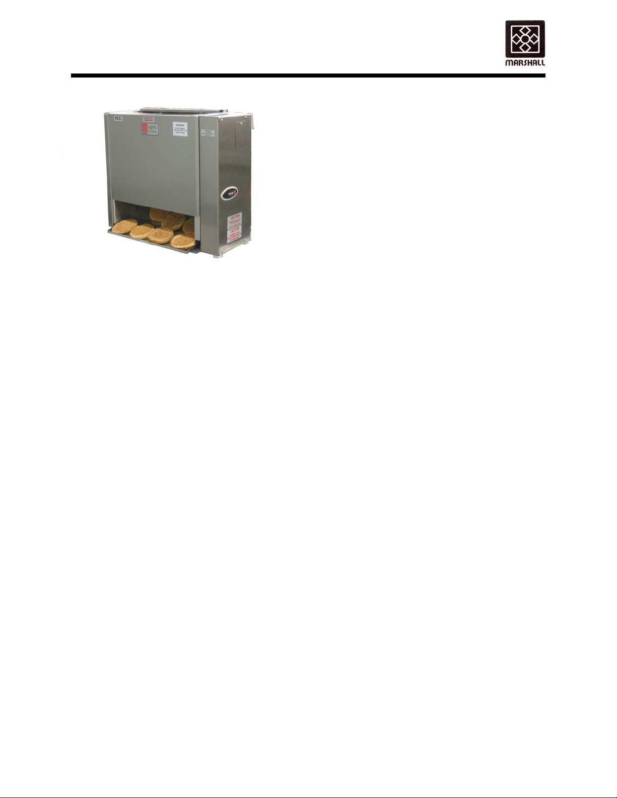
MODEL VT18 AUTOTOAST™ VERTICAL TOASTER
Supplier Name: MARSHALL AIR SYSTEMS, INC.
Address: 419 Peachtree Drive South
Charlotte, NC 28217
Model #: ______________________
Fax #: 704-525-6229
Model VT18
PRODUCT DESCRIPTION
The Marshall Model VT18 Vertical Toaster
produces caramelized buns hot and fast for building
sandwiches to customer orders. This model has a
slim vertical footprint. Buns are loaded at the top
and released onto a product slide at the bottom.
The variable speed drive ranges from 20 seconds
to 2 minutes. Heat controls are fully adjustable from
200- 565F. Left and right side toasting
temperatures can be zoned for flexibility.
All controls are located inside a secured cabinet,
eliminating unauthorized tampering. The toaster is
adjustable for various crown and heel bread
thickness. The multi-control feature options of this
toaster produce and deliver the hottest buns in the
shortest time. The optional Bun Loader allows the
user to load up to 6 buns for toasting.
Serial #’: ______________________
Date Received: ______________________
Date Installed: ______________________
Telephone #: 704-525-6230
Service Referral #: 800-722-3474
Local Service: ______________________
Local Service #: ______________________
GENERAL SPECIFICATIONS
Model: VT18 Vertical Contact Toaster
Height: 22.000”, 29.500” with Optional
Loader
Width: 26.125”
Depth: 13.375, 16.000” with Optional Butter
Wheel
Options: Bun Loader
Butter Wheel
Electrical: 208 VAC, 60Hz, 16 Amps
240 VAC, 50/60 HZ, 19 Amps
Power Cord: 8.0 ft 3 wire ground type UL rated
Plug furnished by others on
International units)
Weight: 103 lbs.
Approvals: ETL/CETL, CSA, CE and NSF
148665 RV012615
Copyright 2013 Marshall Air Systems, Inc.
All Rights Reserved.
Page 2
OWNER’S MANUAL
quip
MODEL VT18 AUTOTOAST™ VERTICAL TOASTER
DO NOT STORE OR USE GASOLINE OR OTHER
FLAMMABLE VAPORS OR LIQUIDS IN THE
VICINITY OF THIS OR ANY OTHER APPLIANCE
Ne pas entreposer ni utiliser de l’essence ni d’autres vapeurs ou liquides inflammables dans
le voisinage de cet appareil, ni de tout autre appareil.
WARNING: IMPROPER INSTALLATION, ADJUSTMENT, ALTERATION, OR MAINTENANCE CAN CAUSE
PROPERTY DAMAGE, INJURY OR DEATH. READ THE INSTALLATION, OPERATION AND MAINTENANCE
INSTRUCTIONS THOROUGHLY BEFORE INSTALLING OR SERVICING THIS EQUIPMENT.
AVERTISSEMENT: Une installation, un ajustement, une altération, un service ou un entretien
non conforme aux normes peut causer des dommages à la propriété, des blessures ou la mort.
Lisez attentivement les directives d’installation et d’opération et d’entretien avant de faire
l’installation ou l’entretien de cet é
KEEP THIS MANUAL IN A SAFE PLACE AND RETAIN FOR FUTURE USE.
Toaster area must be kept free of combustible materials and the flow of ventilation air
must not be obstructed. Operating personnel must not perform any maintenance or
repair functions. Contact your Qualified Service Company.
FOR YOUR SAFETY
AVERTISSEMENT
ement
148665 RV032114
Copyright 2013 Marshall Air Systems, Inc.
All Rights Reserved.
Page 3

OWNER’S MANUAL
MODEL VT18 - VERTICAL CONTACT TOASTER
TABLE OF CONTENTS
PRE INSTALLATION ....................................................................................................................................1
INSTALLATION.............................................................................................................................................1
DAILY CLEANING.........................................................................................................................................2
WEEKLY MAINTENANCE............................................................................................................................3
MONTHLY MAINTENANCE..........................................................................................................................3
QUARTERLY MAINTENANCE.....................................................................................................................3
ANNUAL MAINTENANCE ........................................................................................................................... .4
TOASTER CONTROL DESIGNATION.........................................................................................................4
TROUBLESHOOTING GUIDE...................................................................................................................4-7
REPLACEMENT PARTS ..............................................................................................................................8
CONTROL GENERATION 1 ELECTRICAL REPLACEMENT PARTS.........................................................9
CONTROL GENERATION 2 ELECTRICAL REPLACEMENT PARTS.......................................................10
ILLUSTRATIONS
OVERALL DIMENSIONS-VT18..................................................................................................FIGURE 1, 2
HANG-ON PARTS-VT18.................................................................................................................FIGURE 3
TOASTER PLATEN SHEET-VTI8 ..................................................................................................FIGURE 4
CARRIAGE ASSEMBLY -VT18......................................................................................................FIGURE 5
DRIVE MOTOR ASSEMBLY-VT18.................................................................................................FIGURE 6
SCHEMATICS CONTROL GENERATION 1 (SEE PAGE 4)
VT18 WIRING SCHEMATIC (208V 60HZ, 1PH) VARIABLE SPEED………………………….DWG# 148302
VT18 WIRING SCHEMATIC (240V 50/60HZ, 1PH) VARIABLE SPEED…………………….. DWG# 150218
VT18 (MM2FINTLCE) WIRING SCHEMATIC (240V 50/60HZ, 1PH) ………………….…….. DWG# 157401
148665 RV032114
Copyright 2011 Marshall Air Systems, Inc.
All Rights Reserved.
Page 4

OWNER’S MANUAL
MODEL VT18 - VERTICAL CONTACT TOASTER
SCHEMATICS CONTROL GENERATION 2 (SEE PAGE 4)
VT18 WIRING SCHEMATIC (208V 60Hz 1PH)...................................................................... DWG# 163579
VT18 WIRING SCHEMATIC (220V OR 240V 1PH) .............................................................. DWG # 164071
VT18 WIRING SCHEMATIC (220V OR 240V 1PH) VARIABLE SPEED............................... DWG # 166247
148665 RV111914
Copyright 2011 Marshall Air Systems, Inc.
All Rights Reserved.
Page 5

OWNER’S MANUAL
MODEL VT18 - VERTICAL CONTACT TOASTER
PRE-INSTALLATION
1. The toaster is packaged to prevent the risk of shipping damage. Immediately upon receipt,
inspect the toaster for damage. FILE ALL CLAIMS WITH THE FREIGHT CARRIER.
2. Unpack toaster and remove all protective paper or plastic from metal parts.
FILE ANY CONCEALED DAMAGE CLAIMS WITH THE FREIGHT CARRIER.
3. INSPECTION, TESTING AND REPAIR OF ELECTRICAL EQUIPMENT SHOULD BE
PERFORMED BY QUALIFIED SERVICE PERSONNEL. THE TOASTER SHOULD BE
UNPLUGGED WHEN SERVICING, EXCEPT WHEN ELECTRICAL TEST ARE REQUIRED.
4. It is necessary to check your voltage at the receptacle. The toaster is factory-shipped set at
208V for domestic and 240V for international service. If voltage at receptacle does not match
rating label, it is necessary to simply change a jumper inside the toaster.
CAUTION: DO NOT REMOVE THE ELECTRICAL CONTROL PANEL COVER ON THE RIGHT
SIDE OF TOASTER WITHOUT FIRST TURNING OFF THE TOASTER AND UNPLUGGING
THE CORD.
INSTALLATION
1. Place toaster on a level surface.
2. Check that all panels and covers are in place on the toaster.
3. Check that the toaster platen sheet is installed over the contact platens. The toaster platen sheet
is installed by placing rods into arms of toaster. See Figure 4 .Make sure seam is against platens
(facing top of toaster). USE ONLY MARSHALL APPROVED PLATEN SHEETS OR TOASTER
WARRANTY IS VOID.
4. Check conveyor carriage making sure it is completely seated in saddles and on top pins.
5. Connect the toaster to the power supply.
6. Press and release the “I/O” button on the control. “Lo” will be displayed. Check for free movement
of the conveyor belt.
7. Toaster is ready to use in approximately 15 minutes. Control will display “rdy”.
8. After warm up, insert buns into the top of the toaster. For proper operation, insert heels on the
side of the toaster marked "Heel", and crown on the opposite side. THE CUT SIDES OF THE
HEEL AND CROWN MUST FACE THE TOASTER PLATEN SHEET.
9. The toasted heel and crown will return to the toaster front together. Check the quality of the
toasted buns.
10. Adjust the gap between the conveyor and the toaster heat platens using the two knobs on top of
the toaster (see Figure 1 for knob locations). Both must be lowered at the same time. The knobs
are labeled “HEEL” and “CROWN”. The height gauges in the front indicate whether you are
raising or lowering the platens.
11. The Adjustment Range is .625” – 1.438”.
Contact the factory for instructions.
148665 RV032114 1
Copyright 2012 Marshall Air Systems, Inc.
All Rights Reserved.
Page 6

OWNER’S MANUAL
MODEL VT18 - VERTICAL CONTACT TOASTER
12. The conveyor speed is preset at the factory for 65 seconds. MM2F models set at 45 seconds.
(Please note that the adjustable speed range is 9 to 105 seconds.)
13. Test at least 3 buns before putting the toaster into service. Uniform surface toasting and bun
temperature are achieved when the gap described in step 10 is set correctly.
14. If necessary, the speed of the conveyor can be changed. The speed control is located behind a
cover on the side of the toaster (see Figure 1 for location). Adjust as needed and reinstall cover.
DAILY OPERATION AND CLEANING GUIDE
1. Press and release the “I/O” Button of the control to turn toaster on. “Lo” will be displayed.
CAUTION: DO NOT OPERATE TOASTER WITHOUT ALL PANELS AND COVERS
INSTALLED.
The display of the control will show “Rdy” once the toaster is up to temperature. (Approximately
2.
15 minutes.)
3. For proper operation, insert heels cut side up on the side of the toaster marked "HEEL", and
crowns on the opposite side.
4. To turn off, press the “I/O” Button “Hi” will be displayed which means toaster is still too hot to
remove any parts. Once the toaster has cooled (approximately 30 minutes), the display will show
“Off.”
5. The LED Control will indicate important information:
A. To see temperature settings, press and release either the Heat 1(Left Platen) or the Heat 2
(Right Platen) Button, the pre-programmed temperature settings will flash. This will display
for 5 seconds or until another button is pressed.
B. To see the actual temperature of heaters, press and hold either the Heat 1(Left Platen) or
the Heat 2 (Right Platen) Button for 3 seconds, the actual platen temperatures will be
displayed. This will display until another button is pressed.
6. Definitions of various displays:
“Off” Toaster is off and not operating.
“Lo” Heater platens have not reached programmed set temperature.
“Rdy” Toaster has reached programmed set temperature and is ready to toast.
“Hi” Toaster is off and too hot to touch all removable parts.
“AL1” This is an alarm message that indicates the Left Platen Probe is disconnected or
defective. Toaster automatically shuts off.
“AL2” This is an alarm message that indicates the Right Platen Probe is disconnected
or defective. Toaster automatically shuts off.
“AL3” This is an alarm message that indicates the Left Platen is too hot. Toaster
automatically shuts off.
“AL4” This is an alarm message that indicates the Right Platen is too hot. Toaster
automatically shuts off.
148665 RV032114 2
Copyright 2012 Marshall Air Systems, Inc.
All Rights Reserved.
Page 7

OWNER’S MANUAL
MODEL VT18 - VERTICAL CONTACT TOASTER
DAILY CLEANING
1. Turn toaster off and cool for 30 minutes.
2. Remove conveyor carriage from toaster frame.
3. Take conveyor carriage to sink and spray with water.
4. Clean platen sheet three (3) times daily as listed below.
After lunch rush – Clean sheet in place using a damp cloth or non-abrasive pad. If sheet has
black butter buildup, it must be wiped off. Use Sizzle cleaner if necessary.
After dinner rush – Clean sheet in place using a damp cloth or non-abrasive pad. If sheet has
black butter buildup, it must be wiped off. Use Sizzle cleaner if necessary.
After closing – Remove sheet from toaster. Place on a flat surface and clean using a damp cloth
or non-abrasive pad. If sheet has black butter buildup, it must be wiped off. Make sure to install
sheet seam against platen (facing top of toaster).
5. Inspect platens for butter that has baked-on surface. Scrape off any buildup.
6. Wipe cooling fan louvers on side with a dry cloth or towel.
7. Reinstall all parts after drying.
WEEKLY MAINTENANCE
1. Review and perform Daily and Weekly Maintenance Procedures.
2. Replace any worn out toaster platen sheets with Marshall Part #503983 (4 pack). USE ONLY
MARSHALL APPROVED PLATEN SHEETS OR TOASTER WARRANTY IS VOID.
MONTHLY MAINTENANCE
1. Review and perform Daily and Weekly Maintenance Procedures.
QUARTERLY MAINTENANCE
1. Adjust Belt Tension by Loosing Tension Brackets and pushing toward end of Carriage as you
retighten screws. If tensioning brackets are at the end of adjustment, it is necessary to remove a
link. Tension bracket is shown on Figure 5, see Note for instructions.
2. Check set screws on gears and conveyor sprockets for tightness. Snug these if loose. DO NOT
OVERTIGHTEN.
3. Review and perform Daily, Weekly & Monthly Maintenance Procedures.
148665 RV032114 3
Copyright 2012 Marshall Air Systems, Inc.
All Rights Reserved.
Page 8
OWNER’S MANUAL
MODEL VT18 - VERTICAL CONTACT TOASTER
ANNUAL MAINTENANCE
1. Replace motor brushes (Kit #148549 consists of 2).
2. Perform Quarterly Maintenance.
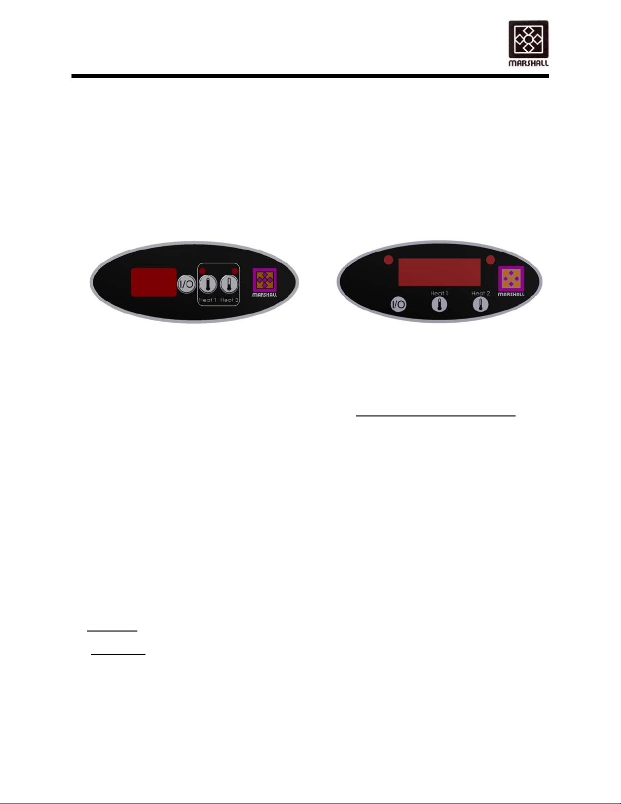
TOASTER CONTROL DESIGNATION
Before any troubleshooting or replacement parts are ordered, it is necessary to determine the
style of control that your toaster has. Generation 2 started in March 2014, but older toasters may
or may not have been field upgraded from Generation 1 to Generation 2.
Buttons to the right of the LED display. Buttons underneath the LED display.
TROUBLESHOOTING GUIDE
NOTE: SERVICE MUST BE PERFORMED BY A QUALIFIED SERVICE COMPANY. THE
WARNING: INSPECTION, TESTING, AND REPAIR OF ELECTRICAL EQUIPMENT SHOULD BE
DANGER: USE EXTREME CARE DURING ELECTRICAL CIRCUIT TESTS. LIVE CIRCUITS
1. PROBLEM: Toaster shuts off intermittently and/or no heat and conveyor belts do not move.
(Will not turn on)
SOLUTION:
A) Check that toaster is plugged in. Check condition of power cord and plug.
B) Check circuit breaker in main breaker panel. Reset if necessary.
C) Check for error message. “AL1” message is a defective left platen probe. “AL2” is a defective
right platen probe. “AL3” is high temperature error of the left platen. “AL4” is high temperature
error of the right platens. All alarms will turn toaster off requiring a service call.
GENERATION 1 GENERATION 2
TERM "QUALIFIED SERVICE COMPANY" MEANS ANY INDIVIDUAL, FIRM,
CORPORATION OR COMPANY WHICH IS EITHER ENGAGED IN AND IS
RESPONSIBLE FOR THE INSTALLATION OR REPLACEMENT OF ELECTRICAL
COMPONENTS, OR THE CONNECTION, INSTALLATION OR REPAIR OF
ELECTRICAL APPLIANCES, WHO IS EXPERIENCED IN SUCH WORK, FAMILIAR
WITH ALL PRECAUTIONS REQUIRED, AND HAS COMPLIED WITH ALL THE
REQUIREMENTS OF THE AUTHORITY HAVING JURISDICTION.
PERFORMED BY QUALIFIED SERVICE PERSONNEL. THE UNIT SHOULD BE
UNPLUGGED WHEN SERVICING, EXCEPT WHEN ELECTRICAL TESTS ARE
REQUIRED.
WILL BE EXPOSED. WHERE TESTING INDICATES "WITH POWER OFF", BE
SURE THAT THE TOASTER IS UNPLUGGED.
148665 RV032114 4
Copyright 2012 Marshall Air Systems, Inc.
All Rights Reserved.
Page 9

OWNER’S MANUAL
MODEL VT18 - VERTICAL CONTACT TOASTER
QUALIFIED SERVICE TECHNICIAN CHECK:
A) Check that there is power at receptacle. Verify voltage is correct based upon the voltage listed on
the toaster nameplate.
B) WITH POWER OFF check connections inside of plug. Remove right side panel and check wiring.
Any wires or terminals with burns or discoloration from arcing should be replaced. All wiring, if
replaced, should be same or higher rated wire.
C) Check sensors to see if ohm readings correct. At room temperature (70˚F), should be nominal
1.09K ohms.
D) With toaster off, check for continuity across the solid state relay terminals #1 and #2. Normal
readings are in megohm range. If reading ohms, relay has failed closed and will not cycle.
E) Control Generation 2 if no LED on display, check for .5 amp transformer fuses. If fuses good,
check for 208 volts on terminals 1 and 6, then 18 Vac on 11 and 12. If 208 volts is present and no
18 Vac output, replace transformer.
2. PROBLEM: Conveyor belts move but no heat.
SOLUTION:
QUALIFIED SERVICE TECHNICIAN CHECK:
A) Check that there is power at receptacle. Verify voltage is correct based upon the voltage listed on
the toaster nameplate.
B) Check for loose connections at terminal strip and temperature terminals (see schematic).
C) Verify that the heater and sensor wires are connected to the controller.
D) Replace all connections or components that have damaged terminals. Replace any damaged
wiring with same or higher rated wire.
E) Check the resistance of the sensor(s). If sensor is open, replace. At room temperature (70˚F),
should be nominal 1.09K ohms.
F) Check voltage into solid-state relays. The voltage input from module should be approximately
5Vdc. Voltage to heater should be 208 or 240Vac.
G) Check the resistance of the heater platens: 24 ohms at room temperature.
H) Control Generation 2 – Check for 24Vdc to the heater relay (R1, R2) from the control board. If
getting 24Vdc from the control board, check for 208 volts on output side of relay. If no 208 volts
then replace relay. If there is 208 volts, then possible solid state relay problem.
3. PROBLEM: Heater platens are hot, control says LO or RDY, conveyor belts do not move.
SOLUTION:
A) Make sure carriage is seated in saddles and top slots are around locator pins.
B) Remove conveyor carriage and turn conveyors by hand and determine there is no binding due to
dropping carriage.
C) Make sure all setscrews on gears are tight.
D) Check motor to make sure it is turning with carriage removed.
E) Increase belt tensioning by loosening tension bracket screws, push toward end as you retighten
screws. If bracket is at the end of adjustment, it is necessary to remove one conveyor link. See
Figure 5.
F) Conveyor carriage has been dropped, bent. Replace carriage.
QUALIFIED SERVICE TECHNICIAN CHECK:
A) Check that there is power at receptacle. Verify voltage is correct based upon the voltage listed on
the toaster nameplate.
148665 RV092314 5
Copyright 2012 Marshall Air Systems, Inc.
All Rights Reserved.
Page 10

OWNER’S MANUAL
MODEL VT18 - VERTICAL CONTACT TOASTER
B) Check the fuses inside the right panel. Replace with type AGC 1.5 amp fuse if necessary.
C) Check for voltage to speed control board. Check for voltage to the motor.
D) Check for red light on the speed board. If red light is lit, the motor is working too hard or in a
stalled state.
E) Some speed boards have a green light. If green light is lit then power is going to the board.
F) Make sure each voltage slide switch of the speed board is set at 230V and 90V as labeled on
the speed board.
G) Check for DC voltage out of board to motor.
H) Check all wiring to motor for loose connectors.
4. PROBLEM: Variable Speed Motor Not Operating
SOLUTION:
QUALIFIED SERVICE TECHNICIAN CHECK:
A) Verify correct voltage to toaster and motor.
B) Check 1.5-amp fuses (#500061) inside right control panel. Replace if necessary.
C) Check for DC voltage to motor out of board (90VDC Motor).
D) If red light on board is on, disconnect load from motor by removing conveyor carriage. If it
goes out, look for conveyor or motor binding. If it stays lit, replace motor – there is probably a
gearbox problem.
E) Check DC amp draw to motor by putting meter in series with motor. (Pull wire from A1 on
board, put one lead to A1, other to wire pulled from A1.) When red LED on board is on, DC
amp reading should be .3 amps approximately.
F) If green LED is on and red is not, make sure that there is varying DC voltage out of board to
motor (terminals A1 & A2 on board) as speed control knob is increased or decreased.
G) Check for oil leaks on motor signifying bad seal or overheating that has taken place. In either
case, motor should be replaced.
H) Check ohm reading at motor cord plug (Range between 50-80 Ohms).
5. PROBLEM: Circuit Board not working properly. DO NOT ADJUST POTS ON BOARD!
SOLUTION:
QUALIFIED SERVICE TECHNICIAN CHECK:
A) Verify AC voltage to board and DC voltage to motor from board. If there is AC voltage in, but
no DC voltage out, replace board.
B) Check all connections on board and terminal strip.
C) Verify that board is wired correctly. (See schematic in Owner’s Manual.)
D) Make sure that one slide switch on board is in 230V position and other is in 90V position.
E) Make sure all wires are connected to potentiometer. A loose wire will make toaster run at
single uncontrolled speed.
F) Control Generation 2 – Check for 24 Vdc from control board to motor relay (R3). If relay is getting
24 Vdc, check for 208 volts on output side of relay. If no 208 volts, replace relay.
6. PROBLEM: Product is over or under toasted.
SOLUTION:
A) Check the gap settings. There must be compression of the bun as it feeds into the toaster.
Decreasing the gap will increase bun temperature and darken surface color. To lower
(decrease gap) turn knob counter-clockwise; to raise (increase gap) turn knob clockwise.
B) Check toast time. Time should be approximately 65 seconds nominal from start to finish.
148665 RV032114 6
Copyright 2012 Marshall Air Systems, Inc.
All Rights Reserved.
Page 11

OWNER’S MANUAL
MODEL VT18 - VERTICAL CONTACT TOASTER
C) Check conditions of toaster platen sheet and belts. Clean both as noted in this manual
D) Make sure conveyor belt is not binding.
E) Check drive system for loose sprockets.
QUALIFIED SERVICE TECHNICIAN CHECK:
A) Check that heaters are cycling. Do this by using an amp clamp on either of the wires from the
controller to the platen. You are looking for cycling. Also verify that the temperature controller
has power.
B) Check platen set temperatures by depressing each button briefly and then check actual
temperatures by holding each button in for 3 seconds.
C) Check that the 3 wires from the speed board are hooked to the speed control.
7. PROBLEM: Buns do not feed properly into toaster.
SOLUTION:
A) Check condition of the toaster platen sheet to be sure buns are not sticking. Clean sheet as
described in daily maintenance. Replace if needed. Sheet should be rotated daily so that the
end of the sheet that is at the bottom is at the top when re-installed.
B) Check toaster platen sheet installation.
C) Toaster gap set too close or too far. See instructions on Page 1, Number 10.
8. PROBLEM: Buns do not exit toaster.
SOLUTION:
A) Check condition of the toaster platen sheet to be sure buns are not sticking. Clean sheet as
described in daily maintenance. Replace if needed. Sheet should be rotated daily.
B) Check toaster platen sheet installation.
C) Toaster platen gap set too close.
9. PROBLEM: Gap setting knobs jammed.
SOLUTION:
A) Turn knobs counter-clockwise. Indicator is read using top
B) Turn both knobs at same time. Platen sheet could be interfering.
10. PROBLEM: Conveyors turning intermittently.
SOLUTION:
A) Make sure carriage is seated in saddles and top slots are around locating pins.
B) Check for bent parts on the carriage.
C) Bearings worn and need replacing.
11. PROBLEM: Motor noisy/chirping.
SOLUTION:
A) Remove motor brushes and inspect. If ¼” or less, replace with new.
B) If longer than ¼”, replace brushes and tighten cap. Do not overly tighten cap.
edge.
148665 RV032114 7
Copyright 2012 Marshall Air Systems, Inc.
All Rights Reserved.
Page 12

OWNER’S MANUAL
MODEL VT18 - VERTICAL CONTACT TOASTER
REPLACEMENT PARTS (See page 9 and 10 for electrical components)
When ordering parts, make sure to specify the model number and serial number as shown by the label
attached on the back of toaster. WARNING: Use of Non Marshall approved parts will void warranty.
It is necessary to determine control style before specifying any electrical components for replacement.
See page 9 and page 10 for information.
PART # DESCRIPTION FIGURE
144074 Arm, Front Tensioning 4
149404 Bar, Chain Support, Kit of 2 5
149278 Bearing, Shaft Rear, Front, Kit of 4 5
148105 Bracket, Motor Mounting 6
148549 Brush Replacement Kit, Motor Set of 2 Not Shown
150426 Butter Wheel (Optional) 3
150429 Butter Wheel Base (Optional) 3
150425 Butter Wheel Kit (Optional) 3
148120 Carriage, Conveyor Asby 3
504102 Conveyor, Toaster 5
148133 Cover, Front 3
150430 Cover, Front For Butter Wheel (Optional) 3
148119 Cover LH Side 3
148118
160837 Cover RH Side (MM2F Only) 3
149279 Gear, Toaster, Drive Kit of 2 5,6
148303 Guard, Heat 3
504016 Idler, 1.405 Dia. (2 Per) 5
161895 Kit, Toaster Foot for HT18 VT18 Toasters Not Shown
504009 Knob, Adjustment 3
502906 Knob, Clear Schematic
148142 Loader, (OPTIONAL) (MM2D Models) 3
131479 Loader, (MM2F Models) 3
144027 Plate, Cover 3
144402 Plate, Idler Tensioning (2 Per ) 5
161452 Ramp, Heated Bun (MM2F Only) 3
144077 Rod, Toaster Platen Sheet 18.250” (1 Per) 4
504018 Screw, #10-32 x 1.500” SS 5
148317 Shaft, Conveyor Drive 5
148318 Shaft, Idler 5
149280 Sheet, Toaster Platen Package of 4 4
148127 Slide, Product (MM2D, MM2DINTLCE & MM2FINTLCE) 3
151097 Spacer, Conveyor Kit (3 Spacers) 5
504046 Spring, Tension (2 Per) 5
144078 Sprocket, Conveyor Asby (2 Per) 5
Cover RH Side (MM2D, MM2DINTLCE &
MM2FINTLCE)
3
148665 RV032114 8
Copyright 2012 Marshall Air Systems, Inc.
All Rights Reserved.
Page 13

OWNER’S MANUAL
MODEL VT18 - VERTICAL CONTACT TOASTER
CONTROL GENERATION 1 ELECTRICAL REPLACEMENT PARTS
(NOTE BUTTON LAYOUT TO RIGHT OF DISPLAY)
PART # DESCRIPTION FIGURE
148150 Circuit Board 230V Schematic
143852 Control, 3 Digit (Control Type 1 Only) Schematic
148301 Control, Module (MM2D Only) (208V Units) Schematic
157400 Control, Module (MM2FINTLCE only) SCHEMATIC Schematic
150214 Control, Module (MM2D Intl, MM2FINTLCE) Schematic
151246 Control, Module (MM2F) Schematic
504011 Cord, 12/3 w/6-20 Plug (MM2D Only) Schematic
504237 Cord, 12/3 3 Wire (MM2FINTLCE, MM2GINTLCE) Schematic
504145 Cord, Set (MM2DINTL) Schematic
144139 Fan, Cooling 240 Vac Schematic
500069 Fuse Holder Schematic
500061 Fuse, 1.5 AMP Schematic
500392 Jumper Schematic
503985 Motor, Right Angle Drive 6,Schematic
503981 Platen, 9” X 12” (2 Per) 6,Schematic
502892 Potentiometer, Rotary Schematic
504313 Relay, Control Schematic
504023 Relay, Solid State Schematic
161003 Sensor, RTD (Note: 2 req’d per toaster) Schematic
502080 Strain Relief for Cord Not Shown
500340 Terminal Strip Schematic
148595 Wiring Harness Platens Not Shown
148665 RV041714 9
Copyright 2012 Marshall Air Systems, Inc.
All Rights Reserved.
Page 14

OWNER’S MANUAL
MODEL VT18 - VERTICAL CONTACT TOASTER
CONTROL GENERATION 2 ELECTRICAL REPLACEMENT PARTS
(NOTE BUTTON LAYOUT UNDER DISPLAY)
PART # DESCRIPTION FIGURE
148150 Circuit Board 230V Schematic
163975 Control Interface Board (LED Control) Schematic
163582 Control I/O Board (MM2F-NC, MM2D-NC) Schematic
164073 Control I/O Board (MM2FINTLCE-NC) Schematic
166249 Control I/O Board (MM2DINTL-NC, MM2DINTLCE-NC) Schematic
504011 Cord, 12/3 w/6-20 Plug (MM2D-NC Only) Schematic
504237
504145 Cord, Set (MM2DINTL-NC) Schematic
144139 Fan, Cooling 240 Vac Schematic
500069 Fuse Holder Schematic
501139 Fuse, .5 AMP Schematic
500061 Fuse, 1.5 AMP Schematic
500392 Jumper Schematic
503985 Motor, Right Angle Drive 6,Schematic
503981 Platen, 9” X 12” (2 Per) 6,Schematic
502892 Potentiometer, Rotary Schematic
504023 Relay, Solid State Schematic
163580 Sensor, RTD Schematic
502080 Strain Relief for Cord Not Shown
500340 Terminal Strip Schematic
504314 Transformer Schematic
148595 Wiring Harness Platens Not Shown
Cord, 12/3 3 Wire (MM2FINTLCE-NC, MM2GINTLCENC)
Schematic
148665 RV012615 10
Copyright 2012 Marshall Air Systems, Inc.
All Rights Reserved.
Page 15

22.000
PLATEN GAP
ADJUSTMENT KNOBS
A
17.000 BUN
LOADING AREA
25.375
DETAIL A
OPTIONAL
LOADER
SPEED CONTROL
IS LOCATED BEHIND
THIS COVER
WITH OPTIONAL
BUTTER WHEEL
MODEL:VT18
OVERALL DIMENSIONS
FIGURE 1
THIS EGDE TO BE USED
TO GAUGE SETTING
29.500
WITH OPTIONAL
LOADER
16.000"
PLATEN GAP
ADJUSTMENT GAUGE
VIEW WINDOW
HEEL LOADING AREA
REMOVABLE HEAT GUARD
NOTE:
UNIT SHOWN WITHOUT
OPTIONAL LOADER OR
OPTIONAL BUTTER WH E EL
THIS VIEW
CROWN LOADING AREA
11.625
13.375
NOTE:
UNITS POWER CORD HAS A
NEMA 6-20 PLUG.
BUN DISCHARGE AREA
MODEL:VT18
OVERALL UNIT ISOMETRIC VIEW
148665FIG1 RV081712
Copyright © 2006 Marshall Air Systems, Inc.
All rights reserved
FIGURE 2
Page 16

#150426
OPTIONAL
BUTTER WHEEL
OPTIONAL
#150425
COVER, RH SIDE
BUTTER WHEEL KIT
MODEL:VT18
HANG-ON PARTS
FIGURE 3
#148133
FRONT COVER
#148118 MM2D, MM2DINTLCE, MM2FINTLCE
#160837 MM2F
#150430
OPTIONAL
BUTTER WHEEL
FRONT COVER FOR
#1444027
COVER PLATE
#150429
OPTIONAL
BUTTER WHEEL BASE
SADDLES
CARRIAGE LOCATOR
PRODUCT SLIDE SINGLE PIECE
#148127 MM2D, MM2DINTLCE, MM2FINTLCE, SOME MM2F
TWO PIECE HEATED RAMP
#161452 MM2F, SOME MM2F
CARRIAGE LOCATOR PINS
#148303
HEAT GUARD
SEE DETAIL A
#504009
SPRING
#502199
ADJUSTMENT KNOB
148665FIG3
Copyright © 2006 Marshall Air Systems, Inc.
All rights reserved
SCALE 1:4
DETAIL A
NUT
#501549
WASHER
RV060413
#501358
COVER, LH SIDE
ASBY #148120
FURTHER DETAIL
SEE FIGURE 5 FOR
CARRIAGE CONVEYOR
#148119
MODEL MM2D
#148142 (SHOWN)
LOADER, OPTIONAL
MODEL MM2F #131479
THIS ROD TO
REST IN CARRIAGE
LOCATOR SADDLE
Page 17

ARM, FRONT TENSIONIN G
#144074
DETAIL A
ROD, TOASTER PLATEN SHEET 18.250"
#144077
A
TOASTER PLATENS
148665FIG4 RV060413
Copyright © 2006 Marshall Air Systems, Inc.
All rights reserved
SHEET, TOASTER PLATEN
#149280
MODEL:VT18
TOASTER PLATEN SHEET
FIGURE 4
Page 18

#149279
CONSISTS OF
(1) DRIVE GEAR
(1) TOASTER GEAR
GEAR, TOASTER KIT
BEARING, REAR, FRONT KIT
#149278
CONSISTS OF
(2) FRONT
(2) REAR
#148317
SHAFT, CONVEYOR DRIVE
#144078
SPROCKET, CONVEYOR ASBY
PLATE, IDLER TENSIONING
#144402
SHAFT, IDLER
#148318
#504046
SPRING, TENSION
NOTE: TO RETENSION CONVEYOR
1. LOOSEN SCREWS
2. PUSH PLATE TOWARD FRONT OF CARRIAGE
3. RETIGHTEN SCREWS
MODEL:VT18
FIGURE 5
#504102
CONVEYOR, TOASTER
IDLER
#504016
#504018
#151097
SCREW, 10-32X1.5
KIT, SPACER CONVEYOR
#149404
CONSISTS OF (2)
BAR, CHAIN SUPPORT KIT
CARRIAGE ASSEMBLY
148665FIG5
Copyright © 2006 Marshall Air Systems, Inc.
All rights reserved
RV060413
Page 19

PLATEN 9" X 12"
#503981
GEAR, DRIVE KIT
#149279
CONSISTS OF
TOASTER AND DRIVE GEAR
MOTOR BRACKET MOUNTING SCREWS
148665FIG6 RV011007
Copyright © 2006 Marshall Air Systems, Inc.
All rights reserved
MOTOR, RIGHT ANGLE DRIVE
#503985
MOTOR MOUNTING BRACKET
#148105
MOTOR MOUNTING SCREWS
MODEL:VT18
DRIVE MOTOR ASSEMBLY
FIGURE 6
Page 20

Page 21

Page 22

Page 23

Page 24

Page 25

 Loading...