

Page 1

This document contains the installation and
operating instructions for:
MODELS: F12 AUTOBROIL OMNI™
FOR YOUR SAFETY
DO NOT STORE OR USE GASOLINE OR OTHER
FLAMMABLE VAPORS OR LIQUIDS IN THE VICINITY OF
THIS OR ANY OTHER APPLIANCE.
INSTRUCTIONS TO PURCHASER:
THIS MANUAL NEEDS TO BE RETAINED FOR FUTURE REFERENCE.
WARNING: IMPROPER INSTALLATION, ADJUSTMENT, ALTERATION, OR MAINTENANCE CAN CAUSE
PROPERTY DAMAGE, INJURY OR DEATH. READ THE INSTALLATION, OPERATION AND MAINTENANCE
INSTRUCTIONS THOROUGHLY BEFORE INSTALLING OR SERVICING THIS EQUIPMENT.
105400 RV100198
Copyright © 1994 Marshall Air Systems, Inc.
All Rights Reserved.
Page 2

MODEL: F12 AUTOBROIL OMNI™
TABLE OF CONTENTS
I. MACHINE SETTING .........................................................................................................…2
II. MACHINE INSTALLATION .................................................................................................3
III. OPERATING INSTRUCTIONS .........................................................................................…4
IV. SCHEDULED MAINTENANCE.......................................................................................... 5
V. TROUBLE SHOOTING ....................................................................................................….6
VI. REPLACEMENT PARTS.................................................................................................…. 8
BROILER LIMITED WARRANTY......................................................................................…i
BROILER WARRANTY PROCEDURES..........................................................................…ii
ILLUSTRATIONS
Conveyor Arrangement................................................................................................................. Figure 1
Control Cabinet, Exterior View...................................................................................................... Figure 2
Bearing, Sprockets and Motor...................................................................................................... Figure 3
Control Cabinet and Internal Layout............................................................................................. Figure 4
Conveyor Belt (Mesh Style).......................................................................................................... Figure 5
Heater Detail................................................................................................................................. Figure 6
Conveyor Adjustment.................................................................................................................... Figure 7
Circuit Board Asby with Mount...................................................................................................... Figure 8
Temperature Controller Replacement Kit..................................................................................... Figure 9
Wiring Schematic Single Belt (208V)............................................................................................ #111140
Wiring Schematic Single Belt (208V)with temperature control connection ..................................#135879
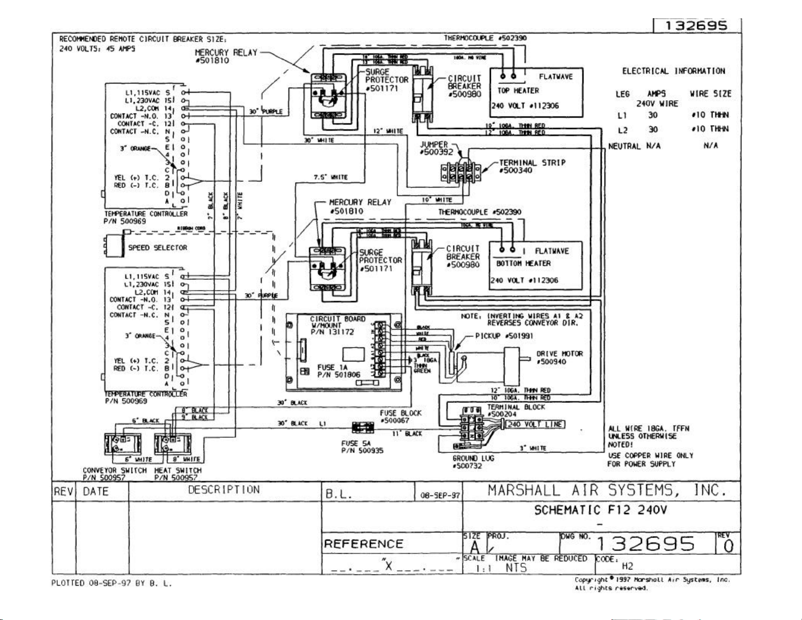
Wiring Schematic (240V).............................................................................................................. #132695
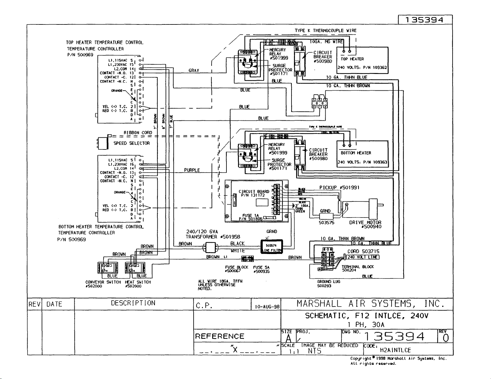
Wiring Schematic (240V) (CE)..................................................................................................… #135394
Wiring Schematic Dual Belt (240V) (CE). ...............................................................................…...#135697
105400 RV100198
Copyright ©1994 Marshall Air Systems, Inc.
All Rights Reserved.
1
Page 3

2
I. MACHINE SETTING
SERIAL NUMBER: ___________________________________________________________________________
VOLTAGE:_________________________________________________________________________________
TEMPERATURE SETTING
TOP TEMPERATURE:________________________________________________________________________
BOTTOM TEMPERATURE:____________________________________________________________________
CONVEYOR SPEED SETTING
___________________________________________________________________________________________
___________________________________________________________________________________________
___________________________________________________________________________________________
START-UP TECHNICIAN:______________________________________________________________________
START-UP DATE:____________________________________________________________________________
COMMENTS:________________________________________________________________________________
___________________________________________________________________________________________
____________________________________________________________________________________________
____________________________________________________________________________________________
105400 RV100198
Copyright ©1994 Marshall Air Systems, Inc.
All Rights Reserved.
Page 4

II. MACHINE INSTALLATION
3
PRE-INSTALLATI0N
1. After uncrating the Autobroil Omni™ unit, inspect for shipping damage. Check that all control
knobs are intact on the electrical cabinet front. Contact the factory if there are obvious problems.
Set the Autobroil Omni™ in place and use the plastic bag to protect it from the debris and trash
of building construction. Check that sideskins have not been dented or damaged by the carrier.
Notify your freight carrier immediately to file a concealed damage claim, following the instructions
attached to the outside of the shipping crate. Your warranty will not cover freight damage.
2. Because this unit is power fan exhausted, it is necessary to provide adequate make up air equal
to the amount removed. In addition to this, any other exhausts, flues, or air removal systems
must be taken into consideration. Examples of this are heat removal fans or hot water heater
flues.
APPLIANCE LOCATION
1. Position Autobroil Omni™ to properly align with exhaust hood. Note nameplate clearance.
2. The hood/ventilation for the appliance should be located in accordance with the National Fire
Protection Association Standard #96, "Removal of Smoke and Grease-Laden Vapors from Commercial Cooking Equipment" and any local applicable requirements.
3. For proper installation, the minimum clearance from combustible construction is 6" from sides
and 6" from back.
4. Adequate clearance should be maintained to allow easy ac cess to loading and unloading areas
of the machine.
5. For servicing, unit must be moved 2" clear from all construction.
ELECTRICAL INFORMATION
1. THE FOLLOWING MUST BE PERFORMED BY A QUALIFIED ELECTRICIAN. Set the unit on
a strong flat equipment stand. Adjust each mounting foot (Figure 1) by turning foot in or out until
the dimension measured at each corner of the machine is IDENTICAL. Place stops or take other
precautions so machine will not accidentally slide off equipment stand.
2. 208 Volt Units: The Autobroil Omni™ unit has a power cord. The cord may be found on the
backside of the unit. The actual electrical amperage requirement of the circuit may be found on
the rating plate on the rear of the unit. Make certain the circuit feeding the machine is sized to
handle the amperage shown on the rating plate, plus a service factor. Use the National Electric
Code as a guide in sizing, wiring and circuit breakers. The power supply is 1 phase, 4 wire, and
the conductors consist of two hot legs (L, and L;), neutral (N) and one ground leg. The neutral
and one hot leg are used to make the control voltage, which should be 120V. The electrician
should check that either both hot legs measure 120V to ground or that, as a minimum, the control circuit (starting at the 5 amp fuse) measures 120V.
3. 240 Volt Units: The power supply is 1 phase, 3 wire, and the conductors consist of two hot legs
(L1 and L2) and one ground wire.
105400 RV100198
Copyright ©1994 Marshall Air Systems, Inc.
All Rights Reserved.
Page 5

4
4. There is a wiring diagram located in this Owner's Manual.
III. OPERATING INSTRUCTIONS
PRE-OPERATI0N CHECK
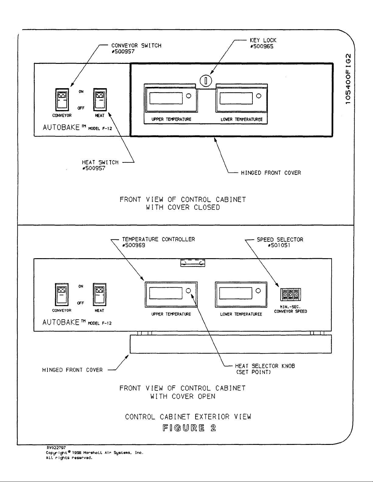
1. After the power has been turned on, cycle the Conveyor ON switch and observe that the conveyor
is moving. Leave the Heat Switch OFF. The Autobroil Omni™ is designed for limited access to the
temperature and speed controls by use of a keylock. The key, which operates the lock, should be
put in a safe place, and should only be used by persons authorized to go inside the Autobroil ™
oven and modify machine settings.
2. Figure 2 shows the front panel of the Autobroil Omni™, as well as the inside panel, which is
visible when the key operated front panel is open. Conveyor speed may be changed by entering. a
new setting in the digital speed selector shown in Figure 2. Speeds available range from 30
seconds to 8 minutes, adjustable in one second intervals.
3. With the locked panel closed, two temperature displays showing the temperature of the top and
bottom heaters are visible. When the Conveyor ON switch is turned to ON, these displays will
illustrate the approximate room temperature. This assumes the Heat ON switch has not yet been
turned ON. If the Heat ON switch is ON, the displays will indicate the temperatures of the
respective heaters as labeled. Again, using the key, access can be made to the inside panel and
the heat selector buttons. See Figure 2. Your Operations Department has established top and
bottom heat settings and generally these should not be touched unless authorized by Operations.
The combination of cooking time and temperatures has been made to produce your food correctly.
When setting temperatures on a new machine, depress the heat selector button and rotate the
button until the displayed temperature is in accordance with operation's required setting. The set
point may be reviewed at any time by depressing the selector button. When not depressed, the
displayed temperature is the actual heater temperature. Perform this temperature setting operation
for the top and bottom heater and then lock the front panel.
4. On the back side of the unit there are two labeled circuit breakers. See Figures 4 and 8. These
circuit breakers control the top and bottom heater power. They are not intended for frequent use,
but are in place to guard against an electrical short developing in the heaters. If one of these circuit
breakers trips, you may reset the breaker, but if it continues to trip, it potentially indicates an
electrical short and that breaker should be left off until the machine is inspected by a qualified
electrician.
SHUT-OFF INSTRUCTIONS
1. When shutting down at night, turn the Heat switches OFF, but leave the conveyor running until the
temperature displayed drops below 500° F (260° C). Allowing the conveyor to run during this cool
down cycle produces improved conveyor and bearing life.
105400 RV100198
Copyright ©1994 Marshall Air Systems, Inc.
All Rights Reserved.
Page 6

5
IV. SCHEDULED MAINTENANCE
DAILY CLEANING PROCEDURES
1. The flat plate top and bottom heaters are self-cleaning, and at most may gather a coating of
ashes due to spillage of food on their surfaces. Removal of these ashes is best accomplished
with a suction device, but if this is not available then the conveyor belt should be opened up
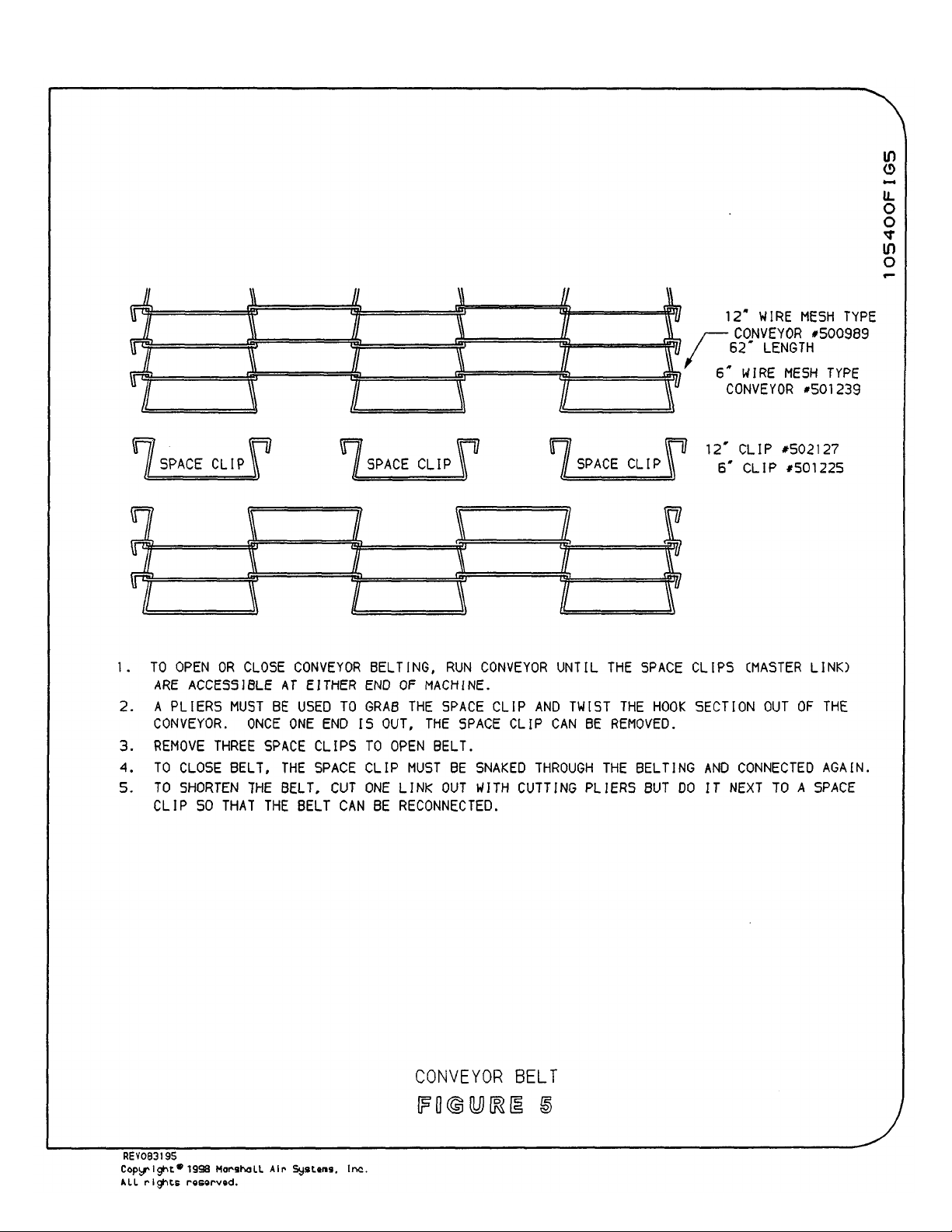
periodically and the heaters brushed clean. Figure 5 illustrates the conveyor chain and the
procedure of opening the conveyor chain.
2. By removing the support trays from each end of the machine, an inspection can be made along
the length of the machine to check for food build-up at each end. This should be scraped and
removed daily to prevent excessive ongoing build-up.
3. Other daily cleaning consists of good housekeeping practices, such as wiping external surfaces.
DO NOT GET WATER ON THE ELECTRICAL CABINET OR ON THE HEATERS. NEVER
HOSE THE MACHINE.
PREVENTIVE MAINTENANCE
1. In addition to daily cleaning, there is little preventive maintenance necessary on the Autobroil
Omni™. Bearings are high temperature, long-life and need no lubrication. They are shown in
Figure 3. After several years of continuous use, it may be necessary to replace the bearings.
They should be replaced with bearings obtained from the Factory only, since they are a special
high temperature type bearing.
2. The drive motor shown in Figures 1 and 3 is a DC type motor that employs motor brushes.
These brushes should be checked for wear on a yearly basis (see Figure 3). Replace the
brushes when they have worn in length to 1/4" or less.
3. Inspect the roller chain in Figure 1 for extensive slack. Remove the slack by loosening the
screws holding the motor in place and sliding the motor down so as to tighten the chain. If no
adjustment remains, then shorten the roller chain.
4. Inspect the conveyor chain at each end of the conveyor for excessive slack, see Figure 7. If
there is excessive slack to the point where the upper run of conveyor may catch the lower run,
check that there is still spring pressure available in the automatic tensioning system. If not,
remove a conveyor link as described in Figure 5.
V. TROUBLESHOOTING
This section contains a list of imagined problems with your Autobroil Omni™ oven. By locating the
problem in this section, you may be able to make a quick repair. ALL ELECTRICAL TROUBLE
SHOOTING INVOLVING ACCESS INTO THE MOTORS. HEATERS OR ELECTRICAL ENCLOSURES
MUST BE PERFORMED BY A QUALIFIED ELECTRICIAN.
1. Temperature displays do not come on when depressing Conveyor ON Switch.
POSSIBLE CAUSE:
A) The 5 amp fuse inside the control cabinet is blown. Figures 4 and Schematic.
105400 RV100198
Copyright ©1994 Marshall Air Systems, Inc.
All Rights Reserved.
Page 7

6
B) Wire is broken off of Conveyor ON Switch. To check, open control panel and inspect Part
#500957 on Figures 4 and Schematic.
2. One of the temperature displays does not indicate correct operating temperature.
POSSIBLE CAUSE:
A) Check appropriate circuit breaker on rear of machine. Figures 4 and Schematic.
B) One of the heater strips in the malfunctioning heater is burned out. To determine this
problem, remove the back skin of the machine and with an amp clamp, measure the
amperage going to the suspect heater. Call Factory to check actual amp draw against
draw recorded at the Factory for the serial number machine involved.
C) Terminal on backside of heater, as shown in Figure 6, has experienced burn off of lead
wire, or loosening of locking nuts. Replace wire to the heater with special high
temperature wire and ring terminals as provided by Factory only.
3. The conveyor does not move.
POSSIBLE CAUSE:
A) Remove motor cover as shown in Figure 1 and check that rubber cord from motor passes
into control cabinet and is not cut or broken.
B) Remove cover over chain that drives conveyor, as shown in Figure 1. Check that set
screws on the sprocket mounted on the motor shaft and the sprocket mounted on the
conveyor axle are tight.
C) Locate circuit board according to information on Figure 4. With control cabinet lid open,
remove the screws and lay inside panel down. This provides access inside the control
cabinet. The motor circuit board has an AGC.1 amp fuse, as shown in Figure 4. Inspect
the fuse and replace with a fuse of identical rating if the original fuse is burned out.
D) Check motor brushes as covered in Figure 3.
4. Temperature of top and bottom heater does not come up to proper setting.
POSSIBLE CAUSE:
A) Check circuit breakers on backside of machine.
B) Check wiring to Heat ON Switch by opening control panel and looking at Heat Switch
#500957. See Figures 4 and Schematic.
5. Temperature display shows letters "OFL".
A) Replace thermocouple of top or bottom heater depending on which display is flashing.
Make certain that new thermocouple is routed exactly like original.
105400 RV100198
Copyright ©1994 Marshall Air Systems, Inc.
All Rights Reserved.
Page 8

With any electrical appliance there are possibilities of failure. The wiring diagram gives a detailed
7
description of the electrical circuits in the control cabinet. Reference to this wiring diagram should be made,
and assistance sought from a local service agency and/or the Factory in pursuing other problems.
VI. REPLACEMENT PARTS
Whenever ordering parts, make certain to specify the machine model number and serial number as shown by
the label attached to the chain guard that covers the drive motor.
PART# DESCRIPTION LOCATION
105400 Owner's Manual F12 N/A
105402 Spare Parts Kit F 12 N/A
105408 Motor Cover Figure 1
105423 Chain Guard Side Skin (Front Left, Rear Right) Figure 1
105426 Cover Plate Figure 1
105446 Tray Loading (F12 Standard) Figure 1
108024 Scare Parts Kit N/A
108192 Drive Motor w/Pick-up (If serial # is 0590093 or older, use this motor) N/A
108749 Bearing Mount Assembly Figure 1,3
109335 Tray Exit Figure 1
110069 Side Skin Middle Figure 1
110657 Side Arm Cover (4) Figure 1
111355 Tray Loading Short Figure 1
112303 Heater Assembly FW 208V w/wires, reflector, sensor N/A
112304 Heater Assembly FW 240V w/wires, reflector, sensor N/A
112305 Heater Assembly FW 208V w/wires N/A
112306 Heater Assembly FW 240V w/wires N/A
116963 Chain Guard Side Skin (Front Right, Rear Left) Figure 1
123805 Temperature Control
130657 Kit, Motor Reversing N/A
131172 Circuit Board w/mount Figure 4
105400 RV100198
Copyright ©1994 Marshall Air Systems, Inc.
All Rights Reserved.
Figure 2,4,
Page 9

PART# DESCRIPTION LOCATION
8
500035 Roller Chain #35 (Per Foot) Figure 1
500040 Sprocket Conveyor Figure 1
500067 Fuse Block 1 Pole Figure 4
500204 Terminal Block Figure 4
500238 Conveyor Sprocket Figure 1
500263 Leg 4" (Optional) Figure 1
500294 Terminal Strip Figure 4
500732 Ground Lug SLU-70 Schematic
500935 Fuse Non 5 Amp Figure 4
500940 Drive Motor (If Serial # is 0590094 or newer, use this motor) Figure 1,3
500941 Motor Brush Figure 3
500957 Heat & Conveyor Switches Figure 2,4
500965 Key Lock Figure 2
500980 Circuit Breaker 25 Amp Figure 4
500989 Conveyor (62" Length sold by foot) Figure 5
501012 Thumbscrews Figure 1
501075 Terminals, 12-10 Gauge, 1/4" Stud Figure 6
501086 Flex Conduit 1/2" (Standard) N/A
501087 Strain Relief 1/2" Flex Connector (Standard) N/A
501157 Sprocket Motor Figure 1
501171 Surge Protector Schematic
501225 Conveyor Belt Space Clip for 6" Mesh Figure 5
501239 Conveyor Belt - Mesh 6" (Per Foot) Figure 5
501671 Key N/A
501806 Fuse 1 Amp AGC (Circuit Board) Schematic
501810 Relay 30 Amp Mercury Figure 4
105400 RV100198
Copyright ©1994 Marshall Air Systems, Inc.
All Rights Reserved.
Page 10

501991 Pick Up Figure 3
9
502127 Conveyor Belt Space Clip for 12" Mesh Figure 5
502199 Conveyor Tensioner Spring Figure 7
502213 Leg 2.5" (Optional) Figure 1
502248 Transformer Schematic
502390 Thermocouple N/A
135848 Control, temp, deg. F 4 digit Schematic
135846 Kit, control, temp, conversion Schematic
502391 Glide Foot (Optional) Figure 1
503529 Jumper, Circuit Board (2) Pin Figure 8
International Parts:
PART# DESCRIPTION LOCATION
501999 Relay 30AMP Schematic
501958 Transformer Schematic
135396 Spare Parts Kit (240V) N/A
105400 RV100198
Copyright ©1994 Marshall Air Systems, Inc.
All Rights Reserved.
Page 11

BROILER LIMITED WARRANTY
RV121096
LIMITED. BRL. DOC
MARSHALL AIR SYSTEMS, INC., ("Marshall") warrants to the first purchaser ("Purchaser") all new equipment of its
manufacture to be free of defects in material and factory workmanship for a period of one year* from date of shipment provided that d)
the squipment is installed in the Continental United States, Canada or Hawaii and operated according to the Owner's Manual while
located at the original address of installation, (ii) the warranty registration card has been completed and returned to the factory within
fifteen (15) days after installation, and (iii) a post-installation start-up has been performed by an authorized service representative
(portable equipment not applicable). Marshall's obligation under this warranty is limited to the repair or replacement at its option of any
defective part. Under certain circumstances, Marshall will reimburse Purchaser for limited labor costs in replacing parts during a period of
not more than ninety (90) days after date of shipment, provided that Labor Reimbursement instructions are followed and items i, ii, and iii
above are completed. See special provision for portable equipment. It is understood that Marshall's obligation with respect to equipment
located outside the Continental United States, Canada or Hawaii is limited to replacement parts only.
Marshall, this warranty DOES NOT COVER:
'hosing or "watering down" equipment will cause electrical failures not covered by warranty);
as a result of improper installation, misuse, abuse, alteration of original design, incorrect voltage, unauthorized service, breakage of
fragile items, or any other damage caused by an act out of Marshall's control.
warranty does not cover cooking performance, smoke capture or holding temperatures which is a function of food types, textures,
temperatures, equipment line ups and other variables chosen by the Purchaser and over which Marshall has no control. This warranty
does not apply to damage caused by accident or to damage caused by the negligence of Purchaser or the employees of Purchaser or to
damage caused by lightning generated electrical current or any other Act of God whatsoever. This warranty does not apply to any
equipment bearing a serial number which has been tampered with or altered. Marshall reserves the right to accept or reject any such
claim in whole or in part. Marshall will not accept the return of any product without prior written approval from Marshall, and all such
approved returns shall be made at Purchaser's sole expense.
WARRANTY OF MERCHANTABILITY AND THE IMPLIED WARRANTY OF FITNESS FOR A PARTICULAR PURPOSE, OR PATENT
OR OTHER INTELLECTUAL PROPERTY RIGHT INFRINGEMENT, AND EXCEPT FOR THE EXPRESS WARRANTY CONTAINED
HEREIN, THE EQUIPMENT IS SOLD "AS IS." REMEDIES UNDER THIS WARRANTY AND UNDER ANY WARRANTY THAT MAY
SURVIVE THE DISCLAIMER OF WARRANTIES ARE LIMITED EXCLUSIVELY TO THOSE REMEDIES DESCRIBED ABOVE. NO
OTHER REMEDY IS AVAILABLE UNDER THIS WARRANTY OR ANY OTHER WARRANTY. NEITHER THIS WARRANTY NOR ANY
OTHER WARRANTY COVERS, AND MARSHALL WILL NOT BE RESPONSIBLE FOR, ANY INCIDENTAL OR CONSEQUENTIAL
DAMAGES, INCLUDING BUT NOT LIMITED TO THE COST OF DISASSEMBLY AND SHIPMENT OF THE EQUIPMENT,
PRODUCTION OR PRODUCT LOSSES, INJURY TO OTHER PROPERTY, OR LOST PROFITS RESULTING FROM THE USE OF OR
INABILITY TO USE THE PRODUCTS OR FROM THE PRODUCTS BEING INCORPORATED IN OR BECOMING A COMPONENT OF
ANY OTHER PRODUCT OR GOODS, OR OTHER LOSSES. WHERE, DUE TO OPERATION OF LAW, CONSEQUENTIAL AND
INCIDENTAL DAMAGES CANNOT BE EXCLUDED, THEY ARE EXPRESSLY LIMITED IN AMOUNT TO THE PURCHASE PRICE OF
THE EQUIPMENT.
*The following broiler parts have a six month part warranty:
• Burner Shields and Screens
• Burner Grids
• Burner Gaskets
• Electric Broiler Elements
• Flame Runners
Because Marshall does not and cannot control Purchaser's installation, use, and maintenance of equipment manufactured by
Any equipment calibration;
Any component disassembled in the field;
Damage due to improper cleaning and/or abuse, i.e. burner rotation, grease accumulation in electrical components or plugs
Blown fuses or bulbs, motor brushes and Teflon components;
Any replacement parts used on the equipment which are not purchased from Marshall;
Accessory components not installed or manufactured by Marshall.
Shipping damage must be reported to the carrier and is not covered under this warranty. Marshall will not be liable for damage
The effect of corrosion, fire, and normal wear on the equipment or component parts is not covered by this warranty. This
THIS WARRANTY IS IN LIEU OF ALL OTHER WARRANTIES, EXPRESS OR IMPLIED, INCLUDING THE IMPLIED
FOR INTERNATIONAL INSTALLATIONS - PLEASE CONTACT YOUR LOCAL
MARSHALL AIR SYSTEMS RECOGNIZED DISTRIBUTOR.
Copyright 1994 Marshall Air Systems, Inc
All Rights Reserved
Page 12

PROCEDUR.BRL.DOC
BROILER WARRANTY PROCEDURES
RETURN GOODS AUTHORIZATION FOR PARTS - FACTORY DIRECT
For prompt warranty parts replacement and RGA processing, please call Marshall's Customer Service
Department at 800-722-3474 or 704-525-6230 for assistance. In all cases, a Return Goods
Authorization (RGA) number must be issued by Marshall Air Systems, Inc. Unauthorized returns will
not be processed.
Option #1: Purchaser to return part prepaid to Factory, Marshall to repair or replace at own
expense if defective, and ship part back to Purchaser prepaid.
Option #2: Marshall to furnish replacement part freight prepaid with or without requesting return of
the defective part.
WARRANTY LABOR REIMBURSEMENT AND/OR PARTS REPLACEMENT THROUGH
RECOGNIZED MAINTENANCE & REPAIR CENTERS
Normally, labor will be covered under the start up fee. In the unlikely event this does not apply, consult Marshall
Air Systems, Inc. To be reimbursed for warranty labor costs, authorization must be given by Marshall Air
Systems, Inc. Unauthorized work will not be reimbursed. Work must be performed by a Marshall Air Systems
Recognized Service Agency within the service time allowance guidelines and must be submitted along with failed
parts (if applicable) to Marshall Air Systems (freight prepaid) within 30 days of the work being performed. Travel
is covered, but must not exceed 50 miles or 1 hour, whichever is greater. Call Marshall's Service Department at
800-722-3474 or 704-525-6230 with any questions. Service is to be performed by recognized service agencies
during normal working hours. Owner to pay for all other charges including excessive travel or overtime charges.
DIAGNOSTIC LABOR CHARGES ARE INCLUDED IN SERVICE TIME ALLOWANCE GUIDELINES. All portable
equipment (under 90 pounds) shall be delivered by Purchaser, at his/her expense, to the nearest authorized
service agency for in-shop repair or at purchaser's discretion he/she will pay all travel time and mileage expenses
for portable equipment.
NON-WARRANTY RETURNS:
All items returned for customer convenience are subject to a 20% restocking fee. In the event of an error by
Marshall Air Systems, Inc., a Returned Goods Authorization will be issued for full credit.
FOR INTERNATIONAL INSTALLATIONS - PLEASE CONTACT YOUR LOCAL
MARSHALL AIR SYSTEMS RECOGNIZED DISTRIBUTOR.
124727 RV042798
Copyright® 1994 Marshall Air Systems. Inc.
All Rights Reserved
Page 13
Page 14

Page 15

Page 16
Page 17

Page 18

Page 19

The F12 broiler has two temperature controllers on the front control panel. This kit is required when replacing an old style temperature controller.
The kit includes two temperature controllers, two transformers, the necessary mounting hardware,
wiring/and instructions. NOTE: IF one of the old style temperature controllers needs replacement, both
temperature controllers must be replaced using this kit.
The old style temperature controller can be identified as part number 500969 and fits into a larger panel
opening than the new style temperature controller part number 135848. The new style temperature
controller has the word "Dixell" on the lower right corner of the faceplate. The kit includes two
transformers because it is operated by 12 volts, and the old style temperature controller was operated
directly by 120 volts.
THIS KIT CONTAINS
1
135847 ADAPTER PLATE FOR NEW STYLE 2 135848 TEMPERATURE CONTROLLER TYPE K
1
136001 ADAPTER BRACKET 1 135849 INSTALLATION INSTRUCTIONS
2
502248 TRANSFORMER, 120V PRI/12V SEC 10VA 1 135879 SCHEMATIC
4
502195 SCR:#8-32 X .375” (F) PAN PH P 1 135880 WIRE SET
1
135846 KIT DRAWING
TEMPERATURE CONTROLLER 4 501015 SCR:#10-32 X .500" (M) TRS PH P
RV022797
Copyright 1998 Marshall Air Systems, Inc.
All rights reserved.
Page 20

Page 21

Page 22
Page 23

Page 24
 Loading...