

Page 1

OWNER'S MANUAL
Important: Keep in safe, easy-to-find location.
TM
Autobroil
Model 713BG
Marshall Air Systems, Inc.
419 Peachtree Drive South
Charlotte, North Carolina USA 28217
704-525-6230
704-525-6229 FAX
Sales and Service
1-800-722-3474
Page 2

Page 3

OWNER’S MANUAL
quip
MODEL 713BG(DB9L,DB9R)/2424G (DB9A) AUTOBROIL™
INSTRUCTIONS TO PURCHASER:
1. ANSI Z83.11 STANDARDS REQUIRE THAT YOU POST IN A
PROMINENT LOCATION THE PROCEDURES TO FOLLOW IN THE
EVENT THE USER SMELLS GAS. THIS INFORMATION SHALL BE
OBTAINED FROM THE LOCAL GAS SUPPLIER.
2. KEEP THIS MANUAL IN A SAFE PLACE AND RETAIN FOR FUTURE
REFERENCE.
FOR YOUR SAFETY
DO NOT STORE OR USE GASOLINE OR OTHER
FLAMMABLE VAPORS OR LIQUIDS IN THE
VICINITY OF THIS OR ANY OTHER APPLIANCE
AVERTISSEMENT
AVERTISSEMENT
Ne pas entreposer ni utiliser de l’essence ni d’autres vapeurs ou liquids inflammables dans le
Ne pas entreposer ni utiliser de l'essence ni d'autres vapeurs ou liquides inflammables dans le voisinage
voisinage de cet appareil, ni de tout autre appareil.
de cet appareil, ni de tout autre appareil.
WARNING: IMPROPER INSTALLATION, ADJUSTMENT, ALTERATION, OR MAINTENANCE CAN CAUSE
PROPERTY DAMAGE, INJURY OR DEATH. READ THE INSTALLATION, OPERATION AND MAINTENANCE
INSTRUCTIONS THOROUGHLY BEFORE INSTALLING OR SERVICING THIS EQUIPMENT.
DO NOT STORE OR USE GASOLINE OR OTHER
FLAMMABLE VAPORS OR LIQUIDS IN THE
VICINITY OF THIS OR ANY OTHER APPLIANCE.
FOR YOUR SAFETY
AVERTISSEMENT: Une installation, un ajustement, une aleration,un service ou un entretien
non conforme aux norms peut casuer des dommages a la propriete, de blessures ou la mort.
Lisez attentivement les directives d’installation et d’operation et d’entretien avant de faire
l’installation ou l’entretien de cet e’
ement
Broiler area must be kept free of combustible materials, and the flow of combustion and
ventilation air must not be obstructed. Operating personnel must not perform any maintenance
or repair functions. Contact your Qualified Service Company.
146267 RV050911
Copyright © 2010 Marshall Air Systems, Inc.
All Rights Reserved.
Page 4

Page 5

OWNER’S MANUAL
MODEL 713BG(DB9L,DB9R)/2424G (DB9A) AUTOBROIL™
TABLE OF CONTENTS
I. BROILER SETTINGS (Quick Reference)............................................................................................. 1
II. BROILER INSTALLATION.................................................................................................................... 2
Pre-Installation ...................................................................................................................................... 2
Broiler Location .................................................................................................................................. 2-3
Electrical Information............................................................................................................................. 3
Gas Piping To Broiler.........................................................................................................................3-4
Pre-Operation Check..........................................................................................................................4-5
Performance Criteria..........................................................................................................................5-6
III. OPERATING INSTRUCTIONS............................................................................................................. 6
Broiler Adjustment-Daily..................................................................................................................... 6-7
Operation of 6-Button Control .......................................................................................................... 7-14
IV. SCHEDULED MAINTENANCE...........................................................................................................14
Cleaning During Operation.................................................................................................................. 14
Daily Cleaning Procedures.............................................................................................................14-16
Weekly Cleaning Procedures.........................................................................................................16-17
Monthly Cleaning Procedures............................................................................................................. 17
Quarterly Cleaning Procedures and Preventive Maintenance ....................................................... 17-18
Biannual Preventive Maintenance....................................................................................................... 18
Annual Preventive Maintenance.....................................................................................................18-19
V. MOTOR SPEED BOARDS .................................................................................................................19
VI. TROUBLESHOOTING...................................................................................................................19-25
VII. INSTRUCTION SHEET FOR CHARcat™ CATALYTIC CONVERTER............................................. 25
Pre-Installation .................................................................................................................................... 25
Installation........................................................................................................................................... 26
Operation............................................................................................................................................. 26
Cleaning.............................................................................................................................................. 26
VIII. REPLACEMENT PARTS............................................................................................................. 27–30
Warranty
ILLUSTRATIONS
Dimensional Drawing ................................................................................................................ Figure 1
External Removable Parts..........................................................................................................Figure 2
Internal Removable Parts...........................................................................................................Figure 3
Drive Assembly .......................................................................................................................... Figure 4
146267 RV050911
Copyright © 2010 Marshall Air Systems, Inc.
All Rights Reserved.
Page 6

OWNER’S MANUAL
MODEL 713BG(DB9L,DB9R)/2424G (DB9A) AUTOBROIL™
Top Burner Assembly................................................................................................................. Figure 5
Hot Surface Pilot System ....................................................................................................... Figure 6, 7
6-Button Control User Interface.................................................................................................. Figure 8
Gas Distribution DB9L................................................................................................................ Figure 9
Loader Assembly ..................................................................................................................... Figure 10
Conveyor Re-tension Adjustment……………………………………………………………………Figure 11
Catalyst Equipped Model 2424G (DB9A)................................................................................. Figure 12
Gas Distribution DB9R ............................................................................................................. Figure 13
Removal of Drive Shaft Assembly for Cleaning ....................................................................... Figure 14
Daily/Weekly Cleaning Instructions .......................................................................................... Figure 15
Spare Parts Kit ......................................................................................................................... Figure 16
Regional Spare Parts Kit.......................................................................................................... Figure 17
Kit, 713BG, CM24 Preventative Maintenance................................................................... Dwg #149268
Control Panel Quick Guide............................................................................................... Dwg # 146269
WIRING SCHEMATICS
Wiring Schematic (713BG, 120V, 1Ph, 60Hz, 6-Button Control)(DB9)............................. Dwg #146203
146267 RV021810
Copyright © 2010 Marshall Air Systems, Inc.
All Rights Reserved.
Page 7

OWNER’S MANUAL
MODEL 713BG(DB9L,DB9R)/2424G (DB9A) AUTOBROIL™
I. BROILER SETTINGS
MODEL:_______________________________________________________________________________
SERIAL NUMBER: ___________________________________________________________________
TYPE OF GAS: ___________________________________________________________________
ELECTRICAL SUPPLY: ______120 VOLT
SCHEMATIC NUMBER___________________ REV. _________
GAS PRESSURE SETTINGS : _SEE PAGE 5_
GAS PRESSURE UPPER BURNERS___________
GAS PRESSURE LOWER BURNERS:
MIN ___________ MAX __
MENU SETTINGS: GAS BROILER
GLOBAL TEMPERATURE
RECIPE BUTTON SPEED
1 __________ _________
2 __________
3 __________
4 __________
5 __________
6 __________
MARSHALL AIR SYTEMS REPRESENTATIVE CONTACT: 1-800 722-3474 _________________________
START-UP TECHNICIAN: ______________________ SERVICE AGENCY: _________________________
ADDRESS: __________________________________ CITY/STATE: __________________ ZIP: ________
TELEPHONE: ___________________ PAGER: ____________________ FAX: ______________________
START-UP DATE: ___________________________________________________________________
COMMENTS: ___________________________________________________________________
___________________________________________________________________________________
___________________________________________________________________________________
___________
AUTOBROIL™
_____________________________________________________
_________
146267 RV021810
Copyright © 2010 Marshall Air Systems, Inc.
All Rights Reserved.
1
Page 8

OWNER’S MANUAL
MODEL 713BG(DB9L,DB9R)/2424G (DB9A) AUTOBROIL™
II. BROILER INSTALLATION
PRE-INSTALLATION
1. After uncrating the Autobroil™ (broiler), inspect for shipping damage. Check that all control knobs
are intact on the electrical cabinet front. Set the broiler in place and leave the plastic wrapping on to
protect it from the debris and trash of building construction. DO NOT remove plug from gas inlet
pipe. Check that broiler has not been dented or damaged by the carrier. To file a concealed damage
claim, follow the instructions attached to the outside of the shipping crate. Warranty does not cover
freight damage.
2. Installation must be performed by a Qualified Service Company
Company" means any individual, firm, corporation or company which is either engaged in and is
responsible for the installation or replacement of gas piping on the outlet side of the meter, or the
service regulator when a meter is not provided, or the connection, installation or repair of gas
appliances, who is experienced in such work, familiar with all precautions required, and has complied
with all the requirements of the authority having jurisdiction.
3. A remote gas shut-off valve must be provided and interlocked to the exhaust fire protection system.
4. This broiler is power fan exhausted, therefore it is necessary to provide adequate make up air equal
to the amount removed. In addition, any other exhausts, flues, or air removal systems must be taken
into consideration. Examples of this are heat removal fans or hot water heater flues.
5. The broiler must be isolated from the gas supply piping system during any pressure testing of the gas
supply piping system at test pressures equal to or less than ½ psig (3.45kPa).
BROILER LOCATION
WARNING: IF NOT INSTALLED, OPERATED AND MAINTAINED IN ACCORDANCE WITH THE
MANUFACTURER'S INSTRUCTIONS, THIS PRODUCT COULD EXPOSE YOU TO SUBSTANCES
IN FUEL OR FROM FUEL COMBUSTION WHICH CAN CAUSE DEATH OR SERIOUS ILLNESS
AND WHICH ARE KNOWN TO THE STATE OF CALIFORNIA TO CAUSE CANCER, BIRTH
DEFECTS OR OTHER REPRODUCTIVE HARM.
1. Position broiler to properly align with exhaust hood (refer to equipment plan). Note nameplate
clearance. The AutoBroil™ is shipped in either a Left to Right or Right to Left configuration based
upon customer designation and if needed can be converted to be opposite configuration. See Figure
8 for details. Attention should be paid to the location of a/c registers and hood makeup air. If air from
either blows into broiler area, cooking and broiler performance will be affected.
2. The exhaust hood/ventilator for the broiler should be located in accordance with the National Fire
Protection Association Standard #96, "Removal of Smoke and Grease-Laden Vapors from
Commercial Cooking Equipment" and any local applicable requirements.
3. For proper installation, the minimum clearance from combustible construction is 0" from sides and 18"
from food loading end and food delivery end.
4. Make sure broiler is level. The grease drainage and collection system may not function if broiler is
not level.
. The term "Qualified Service
146267 021810
Copyright © 2010 Marshall Air Systems, Inc.
All Rights Reserved.
2
Page 9

OWNER’S MANUAL
MODEL 713BG(DB9L,DB9R)/2424G (DB9A) AUTOBROIL™
5. Adequate clearance should be maintained to allow easy access to loading and unloading areas of the
broiler.
6. For servicing, broiler must be moved two feet clear from all surrounding equipment.
CAUTION: KEEP THE BROILER AREA FREE AND CLEAR FROM COMBUSTIBLES.
ELECTRICAL INFORMATION
1. The broiler is furnished with a cord and plug. The broiler requires a 120 Volt A.C., 60 Hz, Single
Phase, 3 wire (including ground), 20 AMP circuit. Broiler must be electrically grounded in accordance
with local codes, or in the absence of local codes, with the National Electrical code ANSI/NFPA No.
70-latest edition.
2. There is a Wiring Diagram located in the Owner's Manual and inside the control cabinet.
WARNING: THIS BROILER IS NOT CAPABLE OF BEING SAFELY PLACED INTO
OPERATION DURING A POWER FAILURE AND NO ATTEMPT TO OPERATE
IT SHOULD BE MADE.
GAS PIPING TO BROILER
1. Installation of this broiler must conform with local codes, or in the absence of local codes, with the
National Fuel Gas Code, ANSI Z-223.1-latest edition.
2. In Canada, this broiler is to be installed in accordance with Standard CGA B149.1 or B149.2
Installation Codes for gas burning appliances and equipment and any local applicable requirements.
3. The broiler is supplied with a 3/4" female pipe thread. The installer must make the pipe connection to
the broiler in accordance with the "National Fuel Gas Code," ANSI Z-223.1-latest edition. The gas
line connected to the 3/4" female pipe thread cannot be less than a 3/4" pipe. The gas pressure and
gas volume required by this broiler is shown on Page 5. Gas piping from source to broiler must be
adequate to satisfy these requirements when all other gas appliances in the restaurant are operating
at maximum demand.
4. A flexible AGA approved gas line is available (#500174 36” flex gas line with restraint). Instructions
are:
(1) The installation shall be made with a connector that complies with the Standard for
Connectors for Movable Gas Appliances, ANSI Z21.699-latest edition, and Addenda
Z21.69a-latest edition, and a quick-disconnect device that complies with the Standard for
Quick-Disconnect Devices for Use With Gas Fuel, ANSI Z21.41-latest edition, and Addenda,
Z21.41a-latest edition and Z21.41b-latest edition and Z21.41b-latest edition.
(2) Adequate means must be provided to limit the movement of the broiler without depending on
the connector and the quick-disconnect device or its associated piping to limit the broiler
movement.
146267 021810
Copyright © 2010 Marshall Air Systems, Inc.
All Rights Reserved.
3
Page 10
OWNER’S MANUAL
p
MODEL 713BG(DB9L,DB9R)/2424G (DB9A) AUTOBROIL™
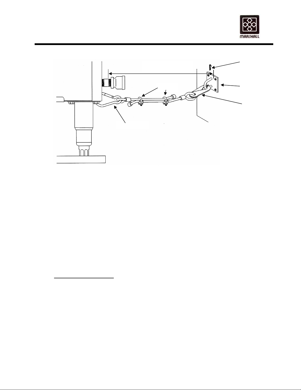
Overall Length
Cotter Pin
Clam
Spring Hook
Optional restraining device is available.
(3) The restraining device must always be connected when the broiler is in operation.
Disconnect for movement necessary for service and cleaning. Then reconnect the restraint
when the broiler has been returned to its normal position.
(4) The restraining device is a separate line and should be no less than 6 inches away from the
gas connector. It should also be in a parallel position to the floor. Using the adjustable
clamps, alter the length of the cable so that the overall length is 3 to 6 inches shorter than the
length of the gas connector including the fittings. Attach the wall bracket to an existing wall
or other architecturally sound surface. Attach scissor hook to the wall bracket and secure
with cotter pin. Finally, attach the spring hook to the gas broiler. Make certain that the
overall length of the line is 3 to 6 inches shorter then the gas connector at this point.
5. See Page 2,Pre-Installation Item 5 for instructions on gas supply line pressure testing.
CAUTION: DO NOT OBSTRUCT THE FLOW OF COMBUSTION AND VENTILATION AIR.
PRE-OPERATION CHECK
Before lighting and operating your broiler, perform a check of critical items as follows:
1. Remove both side panels and check to see that all parts are in place and that none are
damaged. Particularly make sure all burners are in place and that the shields are in position on the
bottom burners.
IMPROPER INSTALLATION OF BURNERS CAN CAUSE FLAME / HEAT DAMAGE TO
COMPONENTS OR WIRING, FOR EXAMPLE THE PILOT WIRES.
2. Start conveyor chains and check for binding. The conveyor chains should run free and not be
catching on any parts.
Wall Bracket
Scissor Hook
146267 021810
Copyright © 2010 Marshall Air Systems, Inc.
All Rights Reserved.
4
Page 11

OWNER’S MANUAL
MODEL 713BG(DB9L,DB9R)/2424G (DB9A) AUTOBROIL™
3. The speed of the conveyor chains should be changed from slow to fast, and back again without the
chain stopping.
4. Before first use, and after any special cleaning, it is necessary to "season" the broiler chain. This is
done by bringing the broiler to operating temperature and then (with burners still lit) applying liquid or
solid shortening from a saturated cloth over the full width of the broiler chain while the chain makes 5
or 6 complete revolutions.
5. Check that gas pressure at broiler gauges is correct (see Performance Criteria shown in chart below).
6. Check that broiler grease tray is in place under burners (see Figure 3).
PERFORMANCE CRITERIA
1. The manifold pressure for each burner and broiler inlet pressure and gas amount is listed below:
Lower burner manifold pressure is measured by a pressure gauge attached to the lower manifold.
With the broiler temperature set to 1000°F the high fire pressure is 5.0 IWC for Natural Gas or 9.0
IWC for LP Gas. High pressure is adjusted using the regulator in the top of the lower burners’ safety
gas valve. Low fire is adjusted using the modulating gas valve. See Figure 9 (DB9L) or Figure 13
(DB9R) for gas system layout. Reset the temperature to 830°F (443°C). Once the broiler reaches
830°F, the gas pressure is varied by the modulating valve to maintain 830°F. (NOTE: Broilers with
catalysts the temperature is set at 960°F.)
To check low pressure, set the temperature to 400°F and the modulating gas valve will drop the lower
burner gas pressure to 1.0 IWC for Natural Gas or 5.4 IWC for LP Gas in an effort to get down to
400°F. Adjust this pressure using the screw located under the plastic cap on the side of the
modulating valve. Figure 9 or 13 . With high and low pressures checked and set, reset the
temperature to 830°F (443°C) which is the correct cooking temperature.
2. The upper burners in the broiler operate at a fixed pressure and are a special infrared type. All of the
air for combustion must be injected through the venturis. This makes orifice design and alignment
very critical. The orifice design, in combination with the correct natural or propane gas pressure will
result in adequate air aspiration and mixing. There are no air shutters. No air adjustment is needed.
TYPE OF GAS:
Natural
LP
Total Gas
Amount
PRESSURE AT
THE BROILER
6.0 - 10.0 IWC
11.0 - 14.0 IWC
146,000 BTUH @ 100 % HIGH FIRE
MANIFOLD PRESSURE
Upper Burners 3.5 IWC
Lower Burners 1.0 IWC to
High 5.0 IWC
Upper Burners 6.4 IWC
Lower Burners 5.4 IWC to
High 9.0 IWC
98,000 BTUH @ IDLE
146267 021810
Copyright © 2010 Marshall Air Systems, Inc.
All Rights Reserved.
5
Page 12

OWNER’S MANUAL
MODEL 713BG(DB9L,DB9R)/2424G (DB9A) AUTOBROIL™
CAUTION: DO NOT STACK BOXES OR IN ANY WAY BLOCK AREA IN IMMEDIATE
VICINITY OF VENTURIS OR IN ANY OTHER WAY OBSTRUCT FLOW OF
COMBUSTION AIR.
3. The flame rod igniter flame is adjustable with a small screwdriver. The cap screw behind the 1/4" gas
line exiting the valve should be removed. The small adjusting screw is under the cap screw. Turning
the small adjusting screw inward (clockwise) will reduce the flame to the igniter. The igniter flame
should be uniform and just large enough to make a flame envelope around the end of the sensor and
igniter.
4. The upper burners will be bright orange when burning properly. If a dull red is observed after 30
minutes of warm-up with a blue flame below the burner face, the orifice may be dirty, damaged, or
misaligned. "Popping," or burning back at the orifice of the burner, is a result of the burner screen
being loose or a faulty gasket under the burner screen. LP broilers may exhibit a light "popping"
sound when the broiler is turned off; this is normal. The lower burners are of a conventional blue
flame type.
NOTE: IF BURNER SCREEN IS TORN OR HAS A HOLE, OR IF A GASKET IS LEAKING,
THE BURNER MUST BE REPAIRED (See Figure 5).
III. OPERATING INSTRUCTIONS
BROILER ADJUSTMENT - DAILY
LIGHTING INSTRUCTIONS FOR ELECTRONIC IGNITION SYSTEM
1. Turn exhaust system on. (Some hoods are so powerful that the broiler must be lit before the exhaust
is turned on).
2. Make sure filters are in place in the hood.
3. Turn broiler on by pressing the On/Off button.
4. The upper burners light first followed by the lower burners 3 minutes later.
5. Verify all of the burners have ignited. Ignition is electronic.
6. If pilot flame or burners fail to light, press the On/Off button for 3 seconds and wait five minutes
before attempting to relight.
7. Allow the broiler burners and conveyor chain to warm up until the control displays “Ready” (with the
chain at approximately the correct speed).
8. Place one meat patty on the broiler chain. Based on the appearance of the broiled patty, reset the
cook time for the desired broiling quality. (Note: this single patty should be cooked to the maximum
degree of the Minimum/Maximum doneness tolerance.)
MANUAL LIGHTING INSTRUCTIONS
1. Remove manifold side cover.
2. Press the On/Off button and hold a flame up to the upper burner igniter.
146267 021810
Copyright © 2010 Marshall Air Systems, Inc.
All Rights Reserved.
6
Page 13
OWNER’S MANUAL
MODEL 713BG(DB9L,DB9R)/2424G (DB9A) AUTOBROIL™
3. Once upper pilot has lit, wait 3 minutes and hold a flame to the lower burner igniter.
This procedure is in case the ignition surface part of the igniter (See Figures 9 & 13) were to break.
If the flame sensor part of the igniter (see Figures 9 & 13) were to break, the igniter must be replaced
immediately.
SHUT-OFF INSTRUCTIONS
1. Press the On/Off button for 3 seconds.
2. The control will display Hot and the conveyors will stop running in approximately 10 minutes.
WARNING: If the cool down waiting period is not observed, the conveyor chain may warp.
3. Turn exhaust system off.
NOTE: Note the gas control knob/slide switch on top of each safety gas valve is "ON". All safety gas
valves with a slide switch will have a clear sealant over the switch and connectors. The sealant
is to help keep water out of the valve. The switch will always be sealed in the “on” position.
OPERATION OF 6-BUTTON CONTROL
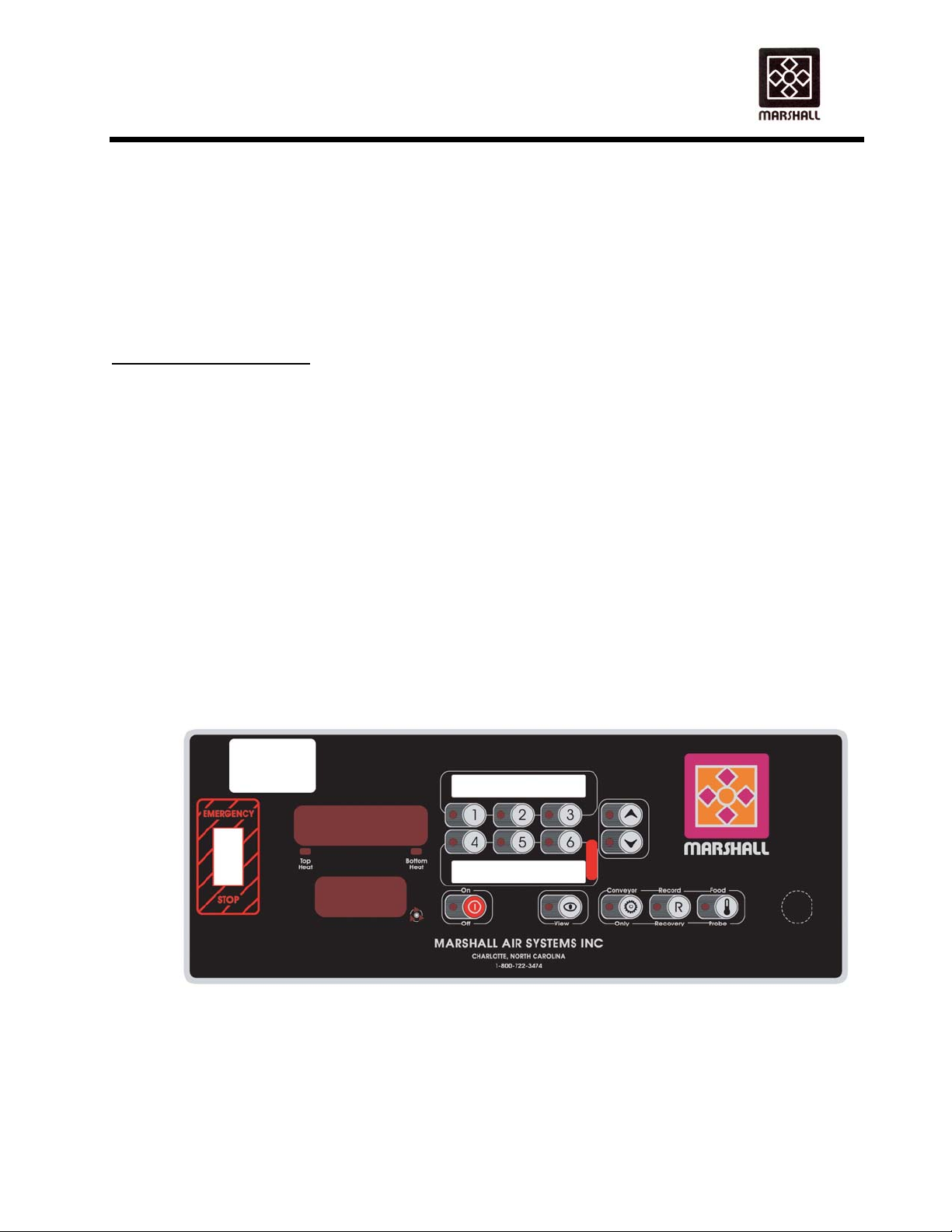
1. USER INTERFACE
The following is the user interface layout.
The Control Panel illustration above shows a typical control interface layout. See Figure 8 for a
description of the buttons. You can also refer to the Control Panel Quick Guide at the end of this
manual.
TIME AND DATE SETUP
146267 021810
Copyright © 2010 Marshall Air Systems, Inc.
All Rights Reserved.
7
Page 14
OWNER’S MANUAL
MODEL 713BG(DB9L,DB9R)/2424G (DB9A) AUTOBROIL™
When the controller is in Off mode, the system Time and Date can be adjusted by pressing the Off
Button for 10 seconds. The time is displayed on the 1
Down Buttons, the hours are changed. Pressing the View Button moves the “focus” to the MM. Use
the Up/Down Buttons to adjust. By pressing View Button again, HH:MM are replaced by DD/MM (or
MM/DD, depending on setting of temperature units) (1
travel from one setting to another, and use the Up/Down Buttons to modify. The View Button will
return to HH:MM. Pressing the Off Button again stores the new Time and Date, and returns to Off
mode.
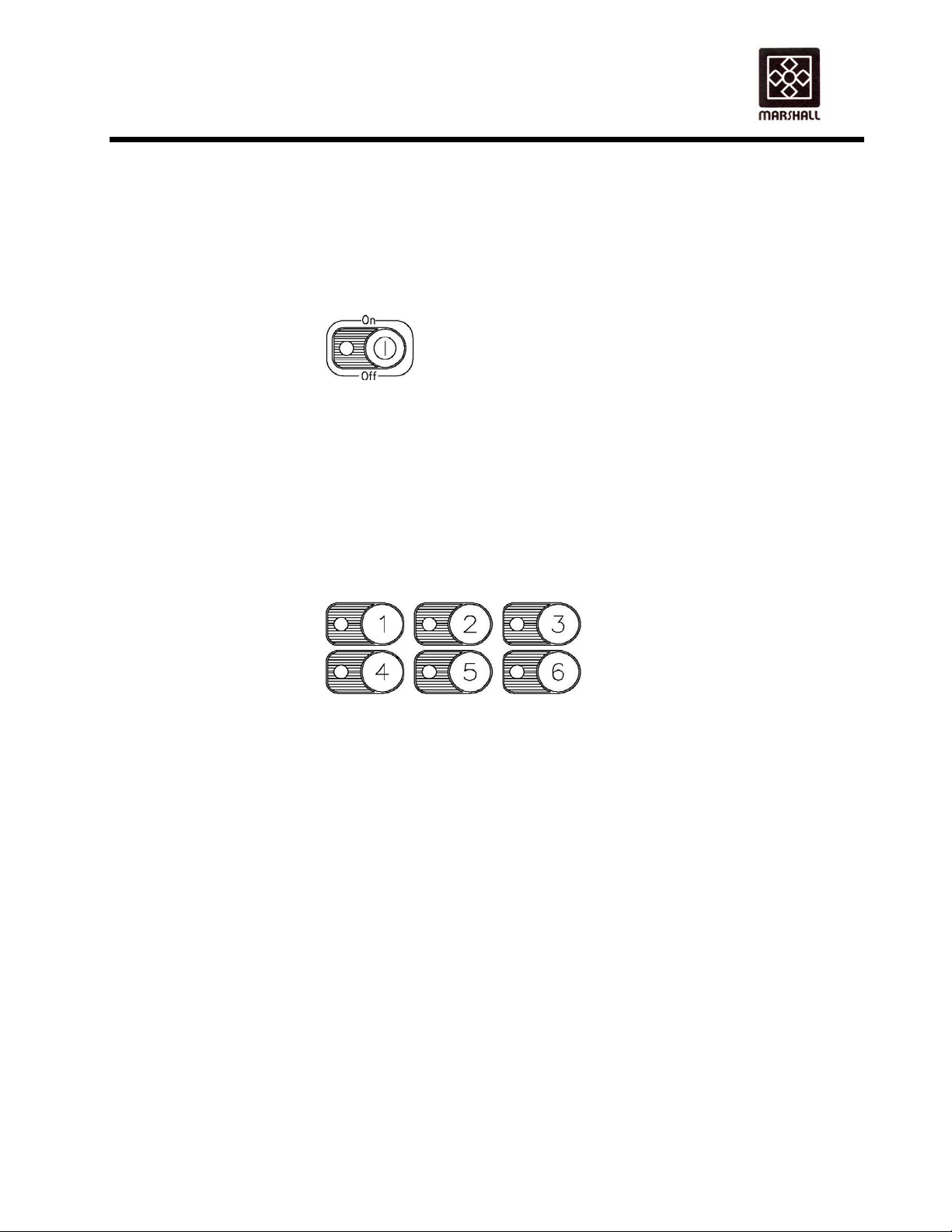
ON/OFF BUTTONS
A normal press of this button turns on the controller. This causes the broiler to start running the
motors at the slowest recipe speed found (overcooked food is safer than undercooked food). This
button also starts the gas ignition system and the burners should light. This recipe is selected (its
corresponding LED lights up) and the temperature set point is the one defined by this same recipe.
At any time in On mode, the user can change the selected recipe. When just turned On, the broiler
will scroll PREHEAT on the 1
st
line until the Soak Time has elapsed. After this time, broiler will display
either READY, LOW or HIGH, depending on the current temperature readings.
A 3-second long press of the On/Off button turns off the broiler. The 1st line will then blink HOT for
the Cool Down period (burners off, but the motors are still running, one at the fastest speed
supported by the broiler, one at the slowest speed supported by the broiler). At that point, the broiler
will then simply display OFF, and all outputs will be disabled.
RECIPE BUTTONS
Recipes, there are 6 of them, are defined by a time and a temperature. The time basically sets the
conveyor speed. All 6 recipes control the conveyor speed. The top three (3) recipe buttons are for
the left conveyor belt and the bottom three (3) buttons are for the right conveyor belt.
When the broiler is READY, a simple press of the recipe button will activate the selected recipe
speed and temperature (LOW and HIGH conditions may or may not be triggered).
When a specific recipe must be changed, keep its button pressed for 3 seconds, until the 1
parameter name scrolls on the 1
will also blink, indicating that they can be used. Pressing either Up or Down the 1
makes the display switch to the parameter’s value (preceded by an arrow, as in ►4.25, to indicate a
changeable value). Subsequent presses will then modify the parameter. If Up or Down are not
pressed for 5 seconds, the display resumes scrolling the parameter name.
Each recipe has 2 programmable parameters. To switch from one to the next, press the recipe
button. After the last parameter is programmed, the broiler resumes normal operation.
- SET COOK TIME,
- SET GAS TEMPERATURE.
Model 713BG Model 2424G
Factory Set Cook time: Button 1-3 =3:20, Factory Set: Button 1=3:15,
st
line SET COOK TIME. The recipe as well as the Up/Down LED’s
st
line, and the HH is blinking. Using the Up and
st
line) and YY (2nd line). Use the View Button to
st
st
time simply
146267 021810
Copyright © 2010 Marshall Air Systems, Inc.
All Rights Reserved.
8
Page 15
OWNER’S MANUAL
MODEL 713BG(DB9L,DB9R)/2424G (DB9A) AUTOBROIL™
4-6 = 3:40 2=3:25,3=3:35,4=4:00,5=4:10,
Factory Set gas temperature: 830°F NAT 6=4:30
800°F LP Factory set gas temperature: 960°F
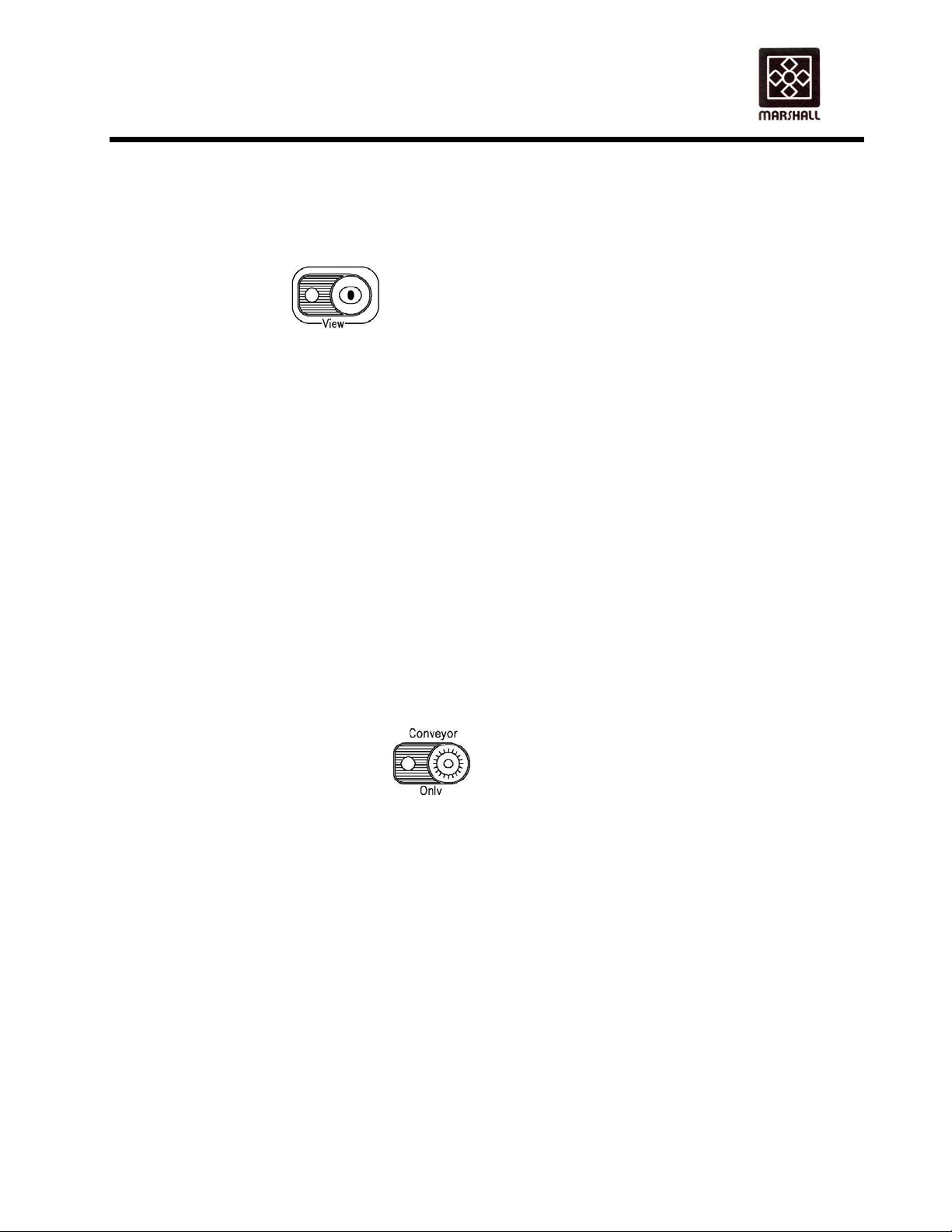
VIEW BUTTON
The View button allows a user to view actual or programmed system parameters. Changes cannot be
made just by using this button.
A simple press of the View button allows the user to see the current broiler temperatures and
conveyor speeds (when not in OFF.) Press the View button to scroll through the available viewable
parameters ( COOKTIME, GAS TEMPERATURE ) When the wanted parameter is displayed, the Up
button is used to toggle between the parameter name and current value. The Down arrow switches
between the current top and bottom recipe speeds (corresponding recipe LED lights up) Pressing the
View button one more time when the last parameter is displayed resumes normal operation. If the
broiler is in OFF mode, then cook times are not displayed. When they are displayed, they are shown
on the 2
Simply pressing the View button shows the current broiler parameters. However, if the View button is
pressed for 3 or more seconds, then the user may view (again, not change) the current recipe
programs. After the View button is pressed for 3 seconds, all recipe LEDs start flashing.
The user then selects the recipe they want to view. COOK TIME is the 1
followed by GAS TEMPERATURE.
Use the selected Recipe button to travel through the parameters. Again, the Up button is used
to see the parameter value. Keep in mind that these are actual recipe programs, and not
current broiler parameters. The blinking recipe LED indicates this. Also, there are no conveyor
speeds displayed on the 2
the broiler resumes normal operation.
CONVEYOR ONLY BUTTON
The Conveyor Only mode allows the broiler user to run the conveyors without heating. This may be
for servicing purposes (such as finding the open link on the conveyor). This mode is accessible only
from the OFF mode. Upon power on of broiler (initialization), the display flashes the software revision
number for example 1.15,1.16 or 1.17. This revision must be known to determine the correct
operation of the Conveyor Only button.
Broilers with release 1.15 - When pressed,SPEED is displayed on the 1
the left belt will turn at 1 minute cook speed. Also the LED for recipe 1 will illuminate. Press VIEW
button 2 more times the right belt will turn at 1 minute. Cook speed and the LED for recipe 4 will
illuminate.
Continuing to press the VIEW button will cycle between the Left and Right belt. The Up/Down
buttons are used to change motor speeds. As soon as the Conveyor Only button is pressed
again, the conveyors stop and the broiler resumes OFF mode
Broilers with release 1.16 - When pressed,SPEED is displayed on the 1
minute cook speed. Also the UP/DOWN LED’s will flash as well as the VIEW LED.
nd
line.
st
parameter viewed,
nd
line in this view mode. As before, once the last parameter is displayed,
st
line. Press the VIEW and
st
line. Both belts turn at 1
146267 021810
Copyright © 2010 Marshall Air Systems, Inc.
All Rights Reserved.
9
Page 16

OWNER’S MANUAL
MODEL 713BG(DB9L,DB9R)/2424G (DB9A) AUTOBROIL™
Continuing to press the VIEW button will cycle between the Left and Right belt. The Up/Down
buttons are used to change motor speeds. As soon as the Conveyor Only button is pressed
again, the conveyors stop and the broiler resumes OFF mode
Broilers with release 1.17 & 2.0- When pressed speed is displayed on the 1
1 minute cook speed. Also the Up/Down & View LED’S will flash.
Pressing the view button once, The LED for Recipe 1 will illuminate. The Left belt motor RPM will be
displayed on the 1
nd
the 2
line. Pressing the view button a second time will display the PWM full scale in the 1st line and
the RPM on the 2
will illuminate, The right belt RPM will be displayed on the 1
scale (17.8=1780) will be displayed on the 2
PWM in full scale will be displayed on the 1
st
line and the Left belt PWM in hundreds scale (17.8=1780) will be displayed on
nd
line for the left motor. A third press of the view button and the LED for Recipe 4
nd
line. A fourth press of the view button the right belt
st
line and the motor RPM will be displayed on the 2nd line.
st
line and the right belt PWM In hundreds
Pressing the view button a fifth time the speed is again displayed on the 1
buttons are illuminated. Any further pressing of the view button will continue this cycle. Pressing the
Up/Down buttons while in any of the Four view modes will increase or decrease the motor RPM for
that belt.
As soon as the conveyor only button is pressed again the conveyor stops and the broiler resumes
OFF mode.
RECORD/RECOVERY BUTTON
This button is available anytime. When pressed, the controller will list a log of the last 3 recovery
times.
A recovery time is the time required for the temperature to go from 200°F to 50°F below factory
set gas temp. This is useful for service and HACCP purposes.
When the Recovery Button is pressed, the controller will successively display GAS1, GAS2 and
GAS3 ramp times, “1” being the most recent ramp logged. To actually see logged time, press the
Up button.
FOOD PROBE BUTTON
This button is useable only when the broiler is On . It is accessible in 2 modes: automatic or manual.
In manual mode, it is up to the user to press the Food Probe button to initiate a log, whereas, the
automatic mode will remind the user (up to 6 times a day) to take a sample. Even in automatic mode,
the user still has the capability to log extra samples manually as he/she wishes.
To do a manual log, the user must first make sure the temperature probe is correctly connected, and
then press the Food Probe Button.
Step #1
This step prepares the controller for logging. It determines the equalization time that will be used
later on in the process.
st
line, Both belts turn at
st
line and no recipe
146267 021810
Copyright © 2010 Marshall Air Systems, Inc.
All Rights Reserved.
10
Page 17

OWNER’S MANUAL
MODEL 713BG(DB9L,DB9R)/2424G (DB9A) AUTOBROIL™
Display: SELECT RECIPE TO LOG is scrolled and recipe LED’s blink.
Sound: None.
User Action: Select the Recipe corresponding to the sample that will be probed.
Step #2
This step starts the logging and gives the user time to set up for the sampling.
Display: Shows INSERT PROBE. Actual temperature can be seen when up button is
pressed. The up button and Record LED’s blink.
Sound: None.
User Action: Insert the Food Probe into the sample according to local sanitary codes and normal
restaurant procedures. Press up button.
Step #3
In this step the temperature continues to be shown to the user. Nothing is being logged yet. The
user must wait until certain temperature is reached (that depends on the specific restaurant
procedures.)
Display: The 1
button LED also blinks.
Sound: None
User Action: Keep Food Probe inserted. When temperature reaches a specific point (known to the
user), the user presses the Record button.
Step #4
In this last step, the actual log is written to memory. The temperature now displayed is logged.
Display: Last temperature read is displayed until Food Probe Button is pressed again. This exits
Food Probe.
Sound: None.
User Action: Remove probe, and press Food Probe Button to resume normal operation.
Data Logged
The following is logged each time a sample is taken (in Step #4):
Date/time stamp (MM/DD/YY if English (degree F), DD/MM/YY if Metric (degree C) as well as
HH:MM)
Recipe number (that was selected by user)
Cook chamber temperature
Food “Start temperature” (when user pressed Record)
Food “End temperature” (when temp was recorded)
NOTE: At the end of Step #4 the user can record another sample of same recipe by pressing Record
again instead of Food Probe, which clears display of previous samples. Display then shows probe’s
current temperature and Steps 3, and 4 are repeated.
UP AND DOWN BUTTONS
These buttons are used to adjust the various system parameters when required. Time is
incremented/decremented at 5-second intervals, and temperature at 5°F (2°C) intervals. These
buttons have a typematic feature associated with them. Keeping them pressed for more than 2
st
line displays the temperature currently measured by the Food Probe. The Record
146267 021810
Copyright © 2010 Marshall Air Systems, Inc.
All Rights Reserved.
11
Page 18

OWNER’S MANUAL
MODEL 713BG(DB9L,DB9R)/2424G (DB9A) AUTOBROIL™
seconds causes the rate of change to accelerate to 25°F/10°C (temperature), or 20 seconds (time)
every 500 msec.
3. DISPLAY
GENERAL
In general, all messages are scrolled on the 1st line (about 2 characters per second), and
times are displayed on the 2
Some buttons have a LED, which is used to indicate various situations.
• On/Off LED: full on when broiler is On, otherwise Off.
• Up/Down LED’s: blink when Up/Down buttons are expected.
• Recipe LED’s: on when a recipe is active, blinking when programming or viewing recipes.
• Conveyor Only: blinking when feature is in use.
• Recovery: full on when feature is in use.
• View: full on when feature is in use.
• Conveyor: this is a group of 3 LED’s that simulate a rotating motion (about 2 changes per
second). This is active whenever the controller is receiving pulses from all installed
tachometers.
• Top and Bottom Heater LED’s: full on when the corresponding heaters are on, otherwise off.
Also, whenever the arrow symbol (X) is displayed with the data, this means that this is a parameter
being changed/adjusted.
TIME DISPLAY
All conveyor speeds are displayed on the 2
displayed as MM.SS, or HH:MM . For example, 9.59 is 9 minutes and 59 seconds, and 1:10 is 1
hour and 10 minutes.
3. SYSTEM STATES
There are several states of operation as follows:
POWER-UP MODE
When a power-up occurs, there is a lamp test, where all LED’s come on for 5 seconds (this includes
all LED’s in the two displays). Following the lamp test, the software number and revision are
displayed. These are useful for troubleshooting purposes when several versions exist in the field.
The first line shows the software number and the second line shows the revision in the format 1.15.
Normally, major release versions will be whole numbers (1.00, 2.00, etc.) and if a fraction occurs,
these are minor release versions.
Following this, the broiler falls automatically into Off mode.
OFF STATE
In this state, the heaters are disabled. Nothing is displayed, except for OFF on the 1
The motors may be used if the Conveyor Only function is used. Also the view and recovery buttons
may be used.
nd
.
nd
line, and are limited to 9.59. All other times are
st
line.
146267 021810
Copyright © 2010 Marshall Air Systems, Inc.
All Rights Reserved.
12
Page 19

OWNER’S MANUAL
MODEL 713BG(DB9L,DB9R)/2424G (DB9A) AUTOBROIL™
ON STATE
This is the normal cooking state. Before displaying READY, the broiler will go through the PREHEAT
mode; The pre-heat mode lasts until the pre-heat Soak Time expires.
In the On mode, 2 extra conditions may exist: LOW and HIGH. Both depend on the current set point,
and the current temperature. If the difference between the set point and the current temperature
exceeds the programmable thresholds, then either the LOW or HIGH messages are displayed. This
warns the user to wait until the READY condition
conveyor. These conditions are likely to occur when a recipe calls for different temperatures.
HOT STATE
This state is active after the broiler is turned Off (or if an error occurs that causes the broiler to shutdown). This state is a cool down step between the On and Off states. The conveyors continue to turn
but the burners are off. The display continuously shows HOT until the Cool Down Time has elapsed,
at which point the OFF message reappears.
4. DIAGNOSTICS
This section describes the various diagnostics errors that are available.
BROILER TEMPERATURE PROBES
comes back before putting product onto the
All probes are type-K probes. All temperature readings normally associated with a type-K probe are
considered valid by the controller. However, if the probes become disconnected or otherwise open,
the controller will sound the buzzer
The defective probe number is displayed on the 2nd line: On the broiler controller, there are two
thermocouples connected together:
• 2 is temperature probes
Pressing any button shuts the buzzer off, but will not remove the error message. The only way to remove
the error message is to resolve the probe and/or connection problem.
and scroll HOT-PROBE ERROR on the 1st line of the display.
When this heater probe errors occurs, the broiler continues operation, at 100% heat. The operator will
most likely then have to adjust the recipe times, but at least the broiler can still operate. Due to
broiler construction, 100% heat for any amount of time is not a problem as the broiler will not “burn” or
otherwise ignite.
EXTERNAL DC ERROR
The DC I/O connector has a +5VDC supply. This supply is internally protected against over-currents.
Should this occur, the broiler will internally disconnect the supply and report HOT-EXTERNAL DC
ERROR. The broiler goes into shutdown (through HOT mode) and the only way to reset this is to
resolve the problem (most likely a short). Since the buzzer is powered through the same +5VDC
supply as the DC I/O connectors, the buzzer does not sound when this error occurs.
After the Cool Down delay, the error message becomes OFF-EXTERNAL DC ERROR instead of
HOT-EXTERNAL DC ERROR.
5. EMERGENCY STOP SWITCH
An emergency stop switch is on the front of the broiler as shown in Figure 8. This switch is for
146267 021810
Copyright © 2010 Marshall Air Systems, Inc.
All Rights Reserved.
13
Page 20

OWNER’S MANUAL
MODEL 713BG(DB9L,DB9R)/2424G (DB9A) AUTOBROIL™
stopping the conveyors and shuts off the gas immediately in case of a conveyor jam or other problem
requiring the broiler to shut down.
Do not use this switch for normal shut downs at the end of the day. Use it if the conveyor jams or you
need to stop the broiler immediately .This switch stops the conveyors and turns off the burners and
turns off power to the control panels. When you turn the Emergency Stop Switch back on, the control
panels will cycle through an initialization, then display OFF. From here you can start as normal.
IV. SCHEDULED MAINTENANCE
CLEANING DURING OPERATION
Grease and Ash removal from Grease Tray.
Use caution when removing the Grease Tray as it will be extremely HOT. DO NOT clean
the Grease Tray in cold water, as cold water will warp the hot Tray. To avoid cooling the
broiler down during cleaning, replace the used Grease Tray with a clean one immediately
after removing the used one. One spare Grease Tray is included with the Broiler.
DAILY CLEANING PROCEDURES
CAUTION: Do not touch the broiler section immediately after broiler shut-down. The temperature
inside enclosures is in excess of 500°F (260°C), which eliminates the need to clean any
parts inside the enclosures for sanitary purposes. Any grease that may build up on the
exterior of the enclosures should be cleaned off with a damp cloth and a minimum
amount of detergent. Never use water on the enclosure or allow burner faces to get
wet as this could cause premature burner or gasket failure. Disconnect the power
supply to the broiler before cleaning or servicing.
CAUTION: UNDER NO CIRCUMSTANCES SHOULD OVEN CLEANER BE USED ON THIS
BROILER. OVEN CLEANER WILL EAT HOLES IN THE ALUMINUM GAS VALVES
AND GAS LINES, CAUSTIC FUMES CAUSE ELECTRICAL COMPONENT DAMAGE,
AND WILL CAUSE MANY OTHER PROBLEMS IF USED TO CLEAN THIS BROILER.
CAUTION: DO NOT ALLOW WATER TO CONTACT THE (3) COOLING FANS. DOING SO MAY
CAUSE THE BROILER TO TRIP THE GROUND FAULT RECEPTACLES AND NOT
OPERATE. PLEASE COVER THE FANS WITH PLASTIC OR OTHER TO PREVENT.
CAUTION: KEEP THE BROILER AREA FREE AND CLEAR FROM COMBUSTIBLES.
1. Allow broiler burners and chain to operate until the control goes from HOT to OFF after cooking last
patty to burn off excess grease on broiler components. (This applies every time a meat chain is
turned off -- regardless of what time of day meat chain is shut down -- and regardless of how few
patties were broiled in the last 30 minutes, last hour, etc.) This will clean some parts of the cooking
chamber. Failure to perform this procedure daily will result in poor cooking times.
2. Turn off broiler, wait 30 minutes and disconnect electricity.
3. Remove all exterior panels except those which are attached with screws. Be careful not to touch
any hot internal broiler components.
146267 021810
Copyright © 2010 Marshall Air Systems, Inc.
All Rights Reserved.
14
Page 21

OWNER’S MANUAL
MODEL 713BG(DB9L,DB9R)/2424G (DB9A) AUTOBROIL™
4. Remove upper burners and reverberators. To remove burners, lift slightly on burner housing and
slide towards the venturi opening in side frame, tilt the burner up and lift out. Shake off all debris.
Hold burners with mesh facing the floor. Brush burner mesh with soft brush. Brush off
reverberators, making sure all debris is removed from all of the openings. Lightly brush out venturi.
DO NOT WASH UPPER BURNERS AS IT WILL DESTROY THE GASKET.
WARNING: THE UPPER BURNER SCREENS (LOCATED UNDER THE TOP BURNERS), ARE MADE
FROM INCONEL METAL MESH. THIS MATERIAL DETERIORATES WITH USE. INSPECT
THESE SCREENS DAILY AND REPLACE IF SCREEN IS SEVERLY CORRODED. FAILURE
TO DO SO CAN RESULT IN METAL PARTICLES BEING SERVED TO YOUR CUSTOMER.
5. Remove lower burners and shields. To remove burners, lift burner positioning end up off of support
and twist burner 90 degrees, tilt burner towards either end of broiler and slide out. Hold burners with
ports facing the floor. Brush burner ports with soft brush. Wash burner shields. Lower burners can
be rinsed.
6. Using a damp cloth, wipe the inside of each burner venturi.
7. Remove the following items and wash with soapy water when they are cool enough to touch with
bare hand. All items can be run through a dish washer.
Cooling Fan Plenum Asby
*
Grease Catch Tray Asby
Grease Pan Asby
*
Product Catch Pan Asby
*
Product Catch Trays
*† Auto Loader Carriage
Entrance Hanging Cover
Hang On Shields (Entrance, Exit)
Loader Arm Cover
Lower Burner Shields (3)
*
Meat Strippers
Shield Entrance, Lower Burner Asby
*
Tunnel Covers (Entrance, Exit)
Tunnel Fillers (2 each)(1Entrance,1Exit)
* NOTE: These items may be removed during the 30 minute cooling period.
† NOTE: Clean items with a green scrub pad.
Figure 3, Item 10
Figure 3, Item 5
Figure 2,Item 9
Figure 2,Item 7
Figure 2, Item 5
Figure 2, Item 1
Figure 2, Item 3
Figure 3, Items 4,6
Figure 2,Item 4
Figure 3,Item 7
Figure 2,Item 6
Figure 3, Item 8
Figure 2 ,Items 2,8
Figure 3,Items 3,11
146267 021810
Copyright © 2010 Marshall Air Systems, Inc.
All Rights Reserved.
15
Page 22

OWNER’S MANUAL
MODEL 713BG(DB9L,DB9R)/2424G (DB9A) AUTOBROIL™
8. Using the conveyor only button on the control which turns the conveyor ON and leaves the heat OFF,
brush the broiler conveyor and, as it cools, wipe with damp cloth.
9. Scrape deposits from the axles with the axle scraping tool, furnished with each machine as shown
below. *THIS IS IMPORTANT TO PREVENT GREASE FIRES AT REAR OF THE BROILER.
Axle Scraper Part Number 100367
The axle scraper provided with the broiler is a handy tool for cleaning the dirt and grime off of the axles. To
insert, place end of scraper in between conveyor and turn scraper as shown in the illustration. Scrape the
axle back and forth. One end of the scraper is made to scrape a ¾” diameter shaft. The other end of the
scraper is made to scrape a 1 1/16” diameter shaft.
10. Remove grease and meat residue from any part of remaining broiler structure where visible. Use a
damp cloth with detergent and a putty knife for best results.
11. After cleaning all removable parts as noted, allow to dry and reassemble.
WEEKLY CLEANING PROCEDURES
1. Perform daily cleaning procedures.
2. Inspect igniters for ash and debris buildup (Figure 9, Item 5).
3. Using a small wire brush or sand paper, lightly clean sensor rod and inside of hood only. Use caution
the sensor rod and glow plug will break easily!
4. Blow loose debris from igniter area.
146267 021810
Copyright © 2010 Marshall Air Systems, Inc.
All Rights Reserved.
16
Page 23

OWNER’S MANUAL
MODEL 713BG(DB9L,DB9R)/2424G (DB9A) AUTOBROIL™
5. If sensor rod or glow plug does break, the igniter must be replaced. Attempt to light manually, then
call service agency.
6. Using a small wire brush and some pressure, brush clean the upper and lower flame runners (Figure
9, Items 2 and 3).
7. Make sure that when cleaning the small ports on the flame runners that all are cleared of any debris
buildup.
8. Remove any loose debris from flame runner area.
9. Remove conveyor and soak in hot soapy water overnight. To remove conveyor, lift front axle up to
produce slack in the conveyor and separate conveyor at the open link. Using the conveyor only
button may be required to locate the open link. If necessary open link with chain pliers (part #500033)
to separate conveyor. When replacing the conveyor, make certain the conveyor is installed properly.
Make reference to the orientation of the conveyor links and the conveyor direction before
reassembly. See Figure 11. PLACING CONVEYOR ON BACKWARD WILL CAUSE SEVERE
BINDING PROBLEMS. CLOSE all open links with pliers to match other links.
10. Remove the Drive Shaft Assembly and clean. (See Figure 14)
11. Clean gas orifices:
a) Orifices are passageways directing gas flow into burners. Uneven gas flow or poor air to gas
ratio is caused by dirty or damaged orifices.
b) Orifices are made of brass. Use special care in cleaning--don't gouge or make gas holes
bigger.
c) To reach orifices, remove burners.
d) Use a chenille stem (similar to a pipe cleaner) or small orifice brush dipped in rubbing alcohol
to clean orifices. Swab until clean; free of carbon build-up. Do not use drill bit; this will
damage the orifices. Chenille stems are available in the craft section of your local
department store or craft store.
MONTHLY CLEANING PROCEDURES
1. Turn off broiler, wait 30 minutes and disconnect electricity.
2. Perform daily & weekly cleaning procedures.
3. Remove roller (drive) chain covers on each side of broiler at exit end. Clean any grease
accumulations.
QUARTERLY CLEANING PROCEDURES & PREVENTIVE MAINTENANCE
1. Perform daily, weekly, and monthly cleaning procedures.
2. Lubricate the roller (drive) chain with a few drops of any grade motor or machine oil.
3. Remove and inspect all motor brushes and replace if less than 1/4" is left.
4. Do not remove internal gas lines for cleaning.
5. Blow out all six (6) burners through the venturi opening with a low
pressure air source.
146267 021810
Copyright © 2010 Marshall Air Systems, Inc.
All Rights Reserved.
17
Page 24

OWNER’S MANUAL
MODEL 713BG(DB9L,DB9R)/2424G (DB9A) AUTOBROIL™
CAUTION: Do not drop burners or get wet the upper burners as this may add to premature
burner failure.
6. Re-tension Conveyor. Refer to Figure 11 for instructions.
7. INVENTORY THE SPARE PARTS KIT AND ORDER MISSING PARTS AS NEEDED. KEEP A
COMPLETE SET OF PARTS ON HAND AT ALL TIMES.
BIANNUAL PREVENTIVE MAINTENANCE
1. Perform daily, weekly, monthly, and quarterly cleaning procedures.
2. Replace lower burner shields with new ones (see Figure 3 ) if excessive corrosion is evident or if they
are cracked or broken.
ANNUAL PREVENTIVE MAINTENANCE
1. Perform daily, weekly, monthly, quarterly and biannual cleaning procedures.
2. Replace upper burner reverberators (see Figure 3) if existing have burn through.
3. Replace lower burner shields (see Figure 3) if existing are cracked or broken.
4. Replace upper flame runner (see Figure 9). Included in Annual parts kit #149268.
5. Replace lower flame runner (see Figure 9). Included in Annual parts kit #149268.
6. Inspect upper burners and replace or rebuild if necessary.
7. Replace Conveyor Bearings. (see Figure 4). Included in Annual parts kit #149268.
8. Replace overdrive tube assembly (see Figure 4). Included in Annual parts kit #149268.
9. Replace upper and lower pilots (igniters). Included in Annual parts kit #149268.
10. Replace burner orifices and flame runner orifices. Included in Annual parts kit #149268.
11. Replace motor brushes in both motors. Included in Annual parts kit #149268.
SPARE PARKS KIT
PART #
135031 CIRCUIT BOARD (SPEED CONTROL)(713BG) 1
146200 CONVEYOR OPEN LINK 7.437” (713BG) 1
146199 CONVEYOR OPEN LINK 13.375” (713BG) 1
146198 CONVEYOR OPEN LINK 24” (CM24) 1
127359 GAS VALVE (LP) 1
502203 GAS VALVE MODULATING (LP) 1
502868 GAS VALVE (NATURAL) 1
DESCRIPTION
QUANTITY
PER KIT
146267 021810
Copyright © 2010 Marshall Air Systems, Inc.
All Rights Reserved.
18
Page 25

OWNER’S MANUAL
MODEL 713BG(DB9L,DB9R)/2424G (DB9A) AUTOBROIL™
PART #
502193 GAS VALVE, MODULATING (NATURAL) 1
154116 IGNITER/SENSOR PILOT (LP) 1
154115 IGNITER/SENSOR PILOT (NATURAL) 1
500083 LINK – HALF (DRIVE CHAIN) 1
500092 LINK – MASTER (DRIVE CHAIN) 1
500940 MOTOR (DRIVE) 1
500033 PLIERS CHAIN 1
501991 PICK - UP 1
148496 THERMOCOUPLE BROILER W/FITTING 1
500277 TIE PLASTIC CABLE 5
V. MOTOR SPEED BOARDS
DESCRIPTION
DC OUTPUT
VOLTAGE SWITCH
QUANTITY
PER KIT
AC SUPPLY
VOLTAGE SWITCH
It is necessary when installing replacement circuit boards, to check the settings of the AC input switches.
1. The AC supply voltage switch must be set at 115.
2. The DC output voltage switch must be set at 180.
VI. TROUBLE SHOOTING
This section contains a list of possible problems with the broiler. ALL ELECTRICAL TROUBLE SHOOTING
INVOLVING ACCESS INTO THE MOTORS OR ELECTRICAL ENCLOSURES MUST BE PERFORMED BY
A QUALIFIED ELECTRICIAN. All items marked with asterisks (*) should be performed by qualified
service personnel certified to perform service on gas fired appliances.
1. PROBLEM
sound like a blowtorch. IMPORTANT: If burner backfires, turn it off. Continued operation will
cause damage to the entire burner.
POSSIBLE CAUSE
A) Burner screen failure (hole) or burner gasket. SOLUTION: Replace burner.
: BURNER BACKFIRES. Flashback, blue flame at entrance to burner makes motor-boating
:
146267 021810
Copyright © 2010 Marshall Air Systems, Inc.
All Rights Reserved.
19
Page 26

OWNER’S MANUAL
MODEL 713BG(DB9L,DB9R)/2424G (DB9A) AUTOBROIL™
* B) Burner over-fired; manifold pressure too high. SOLUTION: Check and reset gas control
regulator to give rating plate/label value for manifold pressure (shown under Performance
Criteria on Page 5). Wait 5 minutes & relight. Flashback will not occur immediately unless a
large opening in or around the burner screen is evident. Wait an hour after relighting to check
that problem is solved. Figure 9 illustrates which regulator sets high and low gas pressures.
C) Check to ensure all screws holding the burner screen in place are snug, if your burner has
removable screens (see Figure 5).
2. PROBLEM
POSSIBLE CAUSE
* A) Low gas pressure. SOLUTION: Check and reset gas control regulator to give rating plate/label
3. PROBLEM
NOTE: ATTEMPT TO LIGHT MANUALLY, THEN CALL SERVICE AGENCY
POSSIBLE CAUSE
A) Wires from pilot assembly loose. SOLUTION: Trace wires to where they plug into gas valve
and check connection (see Figure 9).
B) Wires from pilot assembly damaged/ burned. SOLUTION: Trace wires. If damaged/ burned,
replace pilot. Check lower burners to make sure they are installed fully over orifice.
* C) Pilot assembly dirty or bent. SOLUTION: Check for bent pilot gas line and/or dislodge debris.
* D) Low gas pressure. SOLUTION: Increase gas pressure to broiler (see Figure 9).
* E) Pilot orifice clogged. SOLUTION: Dislodge debris or replace orifice.
F) Grease Pan, cover and or shield not in place. SOLUTION: Make sure all are in place
(see Figure 2&3).
4. PROBLEM
ORANGE WHEN BURNING PROPERLY.
POSSIBLE CAUSE
A) Check that flame runner is fully lit. SOLUTION: If not, clean flame runner orifice or remove and
B) Lower burners dirty. SOLUTION: Check ports are not plugged, clean with wire brush.
C) Lower burner shield bent/broken. SOLUTION: Replace shield.
D) Orifice. SOLUTION: Check that orifice is not plugged. (If it is necessary to change the orifices,
* INSTRUCTIONS MARKED WITH ASTERISKS SHOULD BE PERFORMED BY AUTHORIZED
SERVICE PERSONNEL.
: FLAMES VISIBLE AT EXHAUST STACK OR IN CHAMBER.
:
value for manifold pressure (shown under Performance Criteria on Page 5). Figure 9 illustrates
which regulator sets high and low pressures.
: PILOT FLAME GOES OUT (STUDY FIGURES 6 AND 7 FOR PILOT OPERATION).
:
: BURNER WILL NOT LIGHT AT ALL. NOTE: UPPER BURNERS WILL BE BRIGHT
: (IN ORDER MOST LIKELY TO LEAST LIKELY)
clean flame runner.
new ones must be ordered from the local parts distributor.)
146267 021810
Copyright © 2010 Marshall Air Systems, Inc.
All Rights Reserved.
20
Page 27

OWNER’S MANUAL
MODEL 713BG(DB9L,DB9R)/2424G (DB9A) AUTOBROIL™
E) Hot Surface Ignition, pilot not lit. SOLUTION: Cycle On/Off button or replace igniter.
F) Pilot. SOLUTION: Pilot must light and stay lit in order for burner to light. Check pilot problem
list.
* G) Gas Solenoid. SOLUTION: Check that solenoid valve on main gas valve is working.
* H) Pilot Jumpers. SOLUTION: Check the pilots to make certain they are not plugged.
5. PROBLEM:
POSSIBLE CAUSE
A) Manual On/off switch on the top of the gas valve is turned off. SOLUTION: Turn switch to on
position.
* B) Failed igniter. SOLUTION: Replace igniter.
* C) Failed transformer. SOLUTION: Check for 120 Volts at the primary side of the transformer and
24 Volts on the secondary output. Replace transformer if necessary.
D) Loose connection at gas valve wiring harness. SOLUTION: Check to be sure connector is
securely plugged into the gas valve.
* E) Failed gas valve. SOLUTION: Replace valve and recaulk connectors and manual On/Off switch
in On position.
6. PROBLEM
POSSIBLE CAUSE
A) Check for object caught in conveyor, causing a jam. SOLUTION: Remove object.
B) Check to see if motor shaft is moving. SOLUTION: Sprocket set screw needs to be tightened.
C) Check 1.5 amp fuse on side of the control cabinet. SOLUTION: Turn broiler off, replace fuse,
D) Check 5 amp main power fuse. SOLUTION: Replace if blown.
* E) Connect motor control leads to an operating motor speed control board. SOLUTION: If motor
7. PROBLEM
POSSIBLE CAUSE
* A) Pickup bracket has loosened/Fallen off. SOLUTION: Secure brackets check pickup mounting
( See Figure 4.)
* INSTRUCTIONS MARKED WITH ASTERISKS SHOULD BE PERFORMED BY AUTHORIZED
SERVICE PERSONNEL.
MAIN GAS VALVE(S) DOES NOT WORK.
:
: CONVEYOR CHAIN WILL NOT MOVE.
:
turn broiler on.
runs, replace motor control board. If motor still does not run, replace motor.
: CONVEYOR RUNS BUT SPEED IS CONSTANT
:
146267 021810
Copyright © 2010 Marshall Air Systems, Inc.
All Rights Reserved.
21
Page 28

OWNER’S MANUAL
MODEL 713BG(DB9L,DB9R)/2424G (DB9A) AUTOBROIL™
B) Drive tube is binding with shaft. SOLUTION: Program Left side belt to 1:00 cook time and Right
belt to 6:00 cook time. This may free grease build up.
* C) There are three parts to the motor system. They are the pick-up, the speed circuit board, and
the motor. The parts are listed in the order in which they are most likely to cause a problem.
SOLUTION: Using spare parts, replace one part at a time until the trouble spot is identified.
8. PROBLEM
POSSIBLE CAUSE
A) Tension conveyor- See details in Figure 11.
B) Check to see that chain is not on backward. SOLUTION: See proper chain installation in
Figure 11.
C) Inspect chain closely for bent or warped links that may be snagging and causing a binding
D) Make sure the axle assembly is clean and free of grease and food residue to allow smooth
movement of the conveyor. SOLUTION: Clean axle with axle scraper (see Page 15). Clean
overdrive tube.
E) Check the axle assembly to make certain all set collars, bearings, etc. are properly positioned
and secure. SOLUTION: Reposition set collars, bearings, etc. Tighten set collar set screws.
* F) Disassemble conveyor axle assembly and check condition of bushings and bearings for
excessive wear. SOLUTION: Replace if worn or damaged.
G) Visually inspect the motor drive chain assembly for smooth rotation of chain. SOLUTION:
H) Make sure conveyor is not catching on meat stripper. SOLUTION: Straighten bent stripper.
9. PROBLEM
POSSIBLE CAUSE
A) Meat stripper is dirty. SOLUTION: Clean stripper. (Figure 2)
* INSTRUCTIONS MARKED WITH ASTERISKS SHOULD BE PERFORMED BY AUTHORIZED
SERVICE PERSONNEL.
: REPEATED MECHANICAL BINDING.
:
condition. Also check that the chain links are not climbing out of the sprockets as the conveyor
rotates. SOLUTION: Straighten or replace bad links. Adjust sprockets.
Make certain there are no binding or worn components.
: HAMBURGERS WILL NOT FALL CORRECTLY.
:
146267 021810
Copyright © 2010 Marshall Air Systems, Inc.
All Rights Reserved.
22
Page 29

OWNER’S MANUAL
MODEL 713BG(DB9L,DB9R)/2424G (DB9A) AUTOBROIL™
10. PROBLEM: GROUND FAULT RECEPTACLES TRIP.
POSSIBLE CAUSE
A) Water has seeped into cooling fans. SOLUTION: Turn off cooling fan reset switch located on
back of control cabinet on lower right as viewed when facing the broiler load end. See Figure 1.
It is a toggle switch with a soft rubber boot over the switch making it easy to feel. This will allow
broiler to operate. After one hour, cooling fan reset switch must be turned on.
B) Water has seeped into control cabinet. SOLUTION: Plug broiler into a non-ground fault
receptacle using an extension cord. This will allow broiler to operate and dry out.
11. PROBLEM
POSSIBLE CAUSE
A) Dirty grease pan. SOLUTION: Exchange grease pan with spare clean pan. (See Figure 3.)
B) Cooling fan reset switch turned off. SOLUTION: Turn on cooling fan switch underneath broiler.
12. PROBLEM
POSSIBLE CAUSE:
A) An object (most likely an order ticket) has been sucked into cooling fan. SOLUTION: Shut off
13. PROBLEM
HAS DECREASED OVER A PERIOD OF DAYS.
POSSIBLE CAUSE:
* A) Low gas pressure. SOLUTION: Check gas pressure gauges and correct gas pressures to
B) Hang on covers and burner shields not in place. SOLUTION: Install parts correctly.
C) Holes in the upper three (3) burner reverberators are obstructed. SOLUTION: Clean holes and
reverberators.
D) Burner orifices clogged. SOLUTION: Clean the burner orifices using a chenille stem dipped in
alcohol. Chenille stems are available in the craft section of your local department store or at
your local craft store.
E) Air blowing into broiler chamber for A/C register or exhaust hood makeup air. SOLUTION:
* INSTRUCTIONS MARKED WITH ASTERISKS SHOULD BE PERFORMED BY AUTHORIZED
SERVICE PERSONNEL.
: EXCESSIVE GREASE PAN FIRES.
: CONTINUOUS TICKING SOUND
the fan reset switch located as described in #10. Reach under broiler and look for paper object.
The fan air intake is closest to the back of the electrical cabinet and can be reached from under
the broiler.
: COOK TIMES HAVE HAD TO BE CHANGED BECAUSE BROILER TEMPERATURE
machine settings.
Redirect air flow away from broiler chamber.
:
:
146267 021810
Copyright © 2010 Marshall Air Systems, Inc.
All Rights Reserved.
23
Page 30

OWNER’S MANUAL
MODEL 713BG(DB9L,DB9R)/2424G (DB9A) AUTOBROIL™
F) Lower burner ports are clogged. SOLUTION: Remove burners and clean ports using soft
brush.
G) No item above solves situation. SOLUTION: Record recovery times using control and contact
Marshall Air Customer Service.
14. TROUBLE SHOOTING GUIDE FOR 6-RECIPE BUTTON CONTROLS
The following Error Messages are associated with the 6-Recipe Button controls:
ERROR MESSAGE PROBLEM SOLUTION
LOW
Indicates temperature is below the set point by the programmed amount.
Parts Not In Place Install parts correctly
Gas Valve Off Check Burner Position
Clean Orifices
Clean Flame Runner
Low Gas Pressure Check Gas Pressure
Pilot Burner Not Lit Recycle Heat Switch
Dirty Orifices Clean Orifices
Faculty Display Temperature Check Thermocouples
HIGH
Indicates temperature is above the set point by the programmed amount.
Parts Not In Place Install Parts Correctly
Set Point Set Too Low Check Set Point
Gas Pressure Set Too High Check Pressure
Modulating Valve Minimum Pressure Check Modulating
Set Too High Valve and Pressure
Faculty Display Temperature Check Thermocouples
TACH ERROR or HOT – TACH ERROR or OFF – TACH ERROR
Note: On the lower display window, the number 1 or 2 or 12 will be shown 1 indicates a single conveyor
problem, or a left conveyor problem on a dual conveyor broiler. 2 indicates a right conveyor problem.
When a problem occurs, the first message displayed is TACH ERROR, which almost immediately will cause
the broiler to shut down and display HOT – TACH ERROR. After the cool down period, the broiler will turn off
and display OFF – TACH ERROR
Jammed Conveyor Remove Items Preventing Conveyor From
Moving
Failed Fuse Replace Fuse
Loose Wire or Connector Check wire connections
Loose Pick-up Tighten Pick-Up
Damaged Pick-up Replace Pick-Up
Failed Speed Control Circuit Board Replace Circuit Board
Failed Motor Replace Motor
Failed Speed Module Replace Speed Module
NOTE: If the broiler has two conveyor belts, and you have a TACH ERROR on only one of the conveyors, as
a temporary work around to keep the one working conveyor running you can use the following procedure:
Turn on the broiler using the ON/OFF key. The broiler will start, and you will get a TACH ERROR. The broiler
146267 021810
Copyright © 2010 Marshall Air Systems, Inc.
All Rights Reserved.
24
Page 31

OWNER’S MANUAL
MODEL 713BG(DB9L,DB9R)/2424G (DB9A) AUTOBROIL™
will go into the HOT mode. Press the ON/OFF key once and the tach error beep will stop, press the ON/OFF
key again and the broiler will start the one conveyor that does not have a TACH ERROR. During this
operation, the control will still display the TACH ERROR message, but the broiler will not shut down to the
HOT mode.
This procedure will allow the store operator to continue in operation until a service agency technician can get
to the store to fix the problem.
HOT – PROBE ERROR or OFF – PROBE ERROR
Note: The number on the second line of the control display indicates the thermocouple number.
For electric broilers, 1 indicates the top heater thermocouple, and 2 indicates the bottom heater
thermocouple.
For gas broilers, which have two thermocouples connected in parallel (which acts as one thermocouple to the
control), the display will indicate 2
When a problem occurs, the first message displayed is HOT - PROBE ERROR. After the cool down period,
the broiler will turn off and display OFF – PROBE ERROR.
Loose Thermocouple Fix wiring connection
Failed Thermocouple Replace Thermocouple
Depending on the 6-Recipe Button Control factory setting, some electric broilers will default to 100 percent
heater output to allow the broiler to continue to operate until the problem is fixed. In this case, the recipe cook
time should be temporarily adjusted to achieve the desired cooked product using the 100 percent heat. A
PROBE ERROR message will be displayed until the problem is fixed.
HOT – EXTERNAL DC ERROR or OFF – EXTERNAL DC ERROR
Check Wiring and Connectors For Short Repair Wiring
Failed Pick-up Replace Pick-up
Failed Speed Control Circuit Board Replace Circuit Board
Failed Speed Module Replace Module
Failed Gas Module Replace Module
Failed 6-Recipe Button Control Replace 6-Recipe Button Control
FOOD PROBE ERROR
Food Probe Not Connected Plug in Food Probe
Failed Food Probe Replace Food Probe
CLEAR LOG Log File almost full Clear Food Probe Log File
LOG FULL Log File is full Clear Food Probe Log File
VII. INSTRUCTION SHEET CHARCat™ CATALYTIC CONVERTER INSTALLATION
AND CLEANING
PRE-INSTALLATION
The catalytic converter (catalyst) is packaged to minimize the risk of shipping damage. Immediately upon
receipt, make certain to inspect the broiler for damage. FILE ALL CLAIMS WITH THE FREIGHT CARRIER.
146267 021810
Copyright © 2010 Marshall Air Systems, Inc.
All Rights Reserved.
25
Page 32

OWNER’S MANUAL
MODEL 713BG(DB9L,DB9R)/2424G (DB9A) AUTOBROIL™
INSTALLATION
Prior to installation of a catalyst equipped conveyor broiler in an existing restaurant, your hood duct and fan
system should be cleaned by a professional commercial cleaning service. Refer to Figure 12 and make
certain that all parts related to the catalyst are properly installed.
OPERATION
The catalyst is activated by the exhaust heat from the broiler. There are no extra burners to be added or
electrical components to be connected in order for the catalyst to work. As long as all parts are properly
installed and the broiler calibrated, the catalyst will operate normally. (See broiler owner’s manual for broiler
calibration.)
CAUTION: DO NOT TOUCH THE CATALYST IMMEDIATELY AFTER BROILER SHUT DOWN. THE
TEMPERATURE OF THE CATALYST IS IN EXCESS OF 500°F (260°C), NEVER PUT
WATER ON CATALYST WHILE CATALYST IS HOT. USING WATER ON A HOT
CATALYST WILL CAUSE SEVERE WARPING AND MATERIAL DAMAGE.
CAUTION: UNDER NO CIRCUMSTANCES SHOULD SOAP, DEGREASER, OVEN CLEANER OR
ANY OTHER CLEANING AGENT BE USED ON THE CATALYST. CLEANERS WILL
CAUSE SEVERE DAMAGE.
CAUTION: DO NOT RUN THE CATALYST THROUGH A DISHWASHER.
CLEANING
The catalyst washing procedure is a simple three-step process. The vast majority of the fatty acids deposited
on the catalyst are water-soluble. Care must be taken to use only clean hot water. Soaps, detergents,
bleaches and antioxidants all contain substances which are considered catalyst poisons. In other words, they
will render the catalytic converter inoperable. Clean all foreign matter from the wash basin before starting the
catalyst washing process. The process is as follows:
1. Partially fill a clean wash basin with about 4” of clean hot water (100-130°F). Set the converter
module in the water so that it is completely covered. Let it soak for 15 minutes
2. Remove the module. Shake out the excess water. Drain and rinse the basin thoroughly; then
repeat step 1.
3. Remove the module and rinse through the catalyst with a large volume of hot water. The typical
restaurant rinse nozzle is ideal. Work the spray slowly over the entire surface of the catalyst. DO
NOT USE A HIGH PRESSURE HOSE. Shake the remaining water from the converter module
and allow to dry as time permits. Reinstall on the broiler. The converter is now ready for
normal operation.
4. Rotating the square catalyst from front to back of the broiler when reinstalling the catalyst will
extend the life of the catalyst. This means when it is placed on the broiler, the handles in front
should now be on the back side of the broiler.
Frequency for the above procedure should follow your normal restaurant procedure for cleaning and
sterilization of your food preparation and cooking surfaces but not less than once per week.
146267 021810
Copyright © 2010 Marshall Air Systems, Inc.
All Rights Reserved.
26
Page 33

OWNER’S MANUAL
MODEL 713BG(DB9L,DB9R)/2424G (DB9A) AUTOBROIL™
CATALYST WARRANTY
The catalyst will perform perfectly for a minimum of two (2) years provided the cleaning instructions are
followed. All warranty claims are the responsibility of Engelhard Corporation and subject to their inspection of
the alleged defective catalyst.
VIII. REPLACEMENT PARTS
When ordering parts, make sure to specify the machine model number, type of gas and serial number as
shown by the label attached to the right side cover.
WARNING: USE OF NON- MARSHALL APPROVED PARTS WILL VOID WARRANTY.
PART #
149015 ARM, LOADER ASBY 1 10
150245 BEARING, SLEEVE 1 4
146194 BEARING, TEFLON EXIT 1 4
146193 BEARING,TEFLON EXIT 1 4
503148 BOOT, SWITCH LONG 1 SCHEMATIC
148549 BRUSH, MOTOR KIT (2 BRUSHES) 2 4
115665 BURNER, 24” COMPLETE OPTIONAL 5
127000 BURNER, 24” DISPOSABLE G5B (COMES
WITH NEW BROILERS FOR THE TOP
BURNERS ONLY)
146936 BURNER,LOWER TUBULAR 3 3
152110 BURNER,LOWER TUBULAR LP 3 3
146260 CAP, OVERDRIVE SHAFT 1 4
145530 CARRIAGE, AUTO LOADER ASBY 1 2,10
148022 CATALYST CHARCAT 1 12
500035 CHAIN, ROLLER #35 (3.55 FT) 2 4
135031 CIRCUIT BOARD SET FOR 120V 2 SCHEMATIC
150432 COLLAR, BEARING LOCK 1 4
150433 COLLAR, IDLER 1.750” OD, .755” ID 2 4
500117 COLLAR, SET 0.505”ID X 0.875” OD 2 10
145871 CONTROL, 6 BUTTON HORIZONTAL 1 SCHEMATIC
145690 CONVEYOR, 6” MESH 1 10
145689 CONVEYOR, 12” MESH 1 10
503560 CONV BELT, 13.75 “ ROD , 7GA. (6FT) 1 11
503561 CONV BELT, 7.437” ROD, 7GA. (6FT) 1 11
147520 COOLING FAN PLENUM ASBY (DB9L)(DB9) 1 3
149030 COOLING FAN PLENUM ASBY (DB9R) 1 3
502411 COUPLING, BRASS ¼ COMP X 1/8 1 9, 13
146425 COVER, ENTRANCE HANGING 1 2
146432 COVER, LH SIDE ASBY (DB9L)(DB9) 1 2
146908
145752
146431 COVER, MANIFOLD SIDE ASBY (DB9L)(DB9) 1 2
149039 COVER MANIFOLD SIDE ASBY (DB9R) 1 2
146136 COVER,TUNNEL 2 2
COVER, LOADER ARM
(S/N 0605B03427, 0605B03428 ONLY)
DESCRIPTION
QUANTITY
PER BROILER
3 3
1 2
FIGURE
146267 021810
Copyright © 2010 Marshall Air Systems, Inc.
All Rights Reserved.
27
Page 34

OWNER’S MANUAL
MODEL 713BG(DB9L,DB9R)/2424G (DB9A) AUTOBROIL™
PART #
149040 COVER RH SIDE ASBY (DB9R) 1 2
116084 CROSS TUBE, .5” DIA X 24.875” 1 10
146650 DIVERTER, AIR ASBY 1 3
DRIVE ASBY, 713BG COMPLETE SHAFT,
150399
502413 ELBOW, BRASS ¼ COMP. X 1/8 FTP 2 9, 13
148013 ENTRANCE TUNNEL COVER ASBY 1 12
148017 EXIT TUNNEL COVER ASBY 1 12
504059 FAN, COOLING 3 SCHEMATIC
146050 FILLER,TUNNEL,ENTRANCE 1 3
146101 FILLER, TUNNEL ,EXIT 1 3
146403 FLAME RUNNER, LOWER BURNER ASBY 1 9, 13
146401 FLAME RUNNER, UPPER BURNERS ASBY 1 9, 13
148006 FRAME ASBY, CATALYST 1 12
501139 FUSE 0.5 A 1 SCHEMATIC
500061 FUSE 1.5A 2 SCHEMATIC
502739 FUSE 5A 1 SCHEMATIC
502631 GAS FLEX- TUBE, 5/8” X 12” 1
144321 GEAR, 28 TOOTH 20DP IDLER 2 10
500070 GUAGE, GAS 0-15 IWC ¼” MPT 2 9, 13
146133 GUARD, MOTOR CHAIN 1 2
146134 GUARD, MOTOR CHAIN 1 2
145751 IDLER, ASBY 2 10
145698 IDLER, GEAR/ SPROCKET ASBY 2 10
154116 IGNITER ASBY LP 2 9, 13
154115 IGNITER ASBY NAT 2 9, 13
149268 KIT,ANNUAL PARTS REPLACEMENT 1 Not Shown
124630 KIT, BURNER SCREEN TO REBUILD BURNER OPTIONAL 5
151071 KIT, GEAR AND WASHER 1 10
151072 KIT, IDLER AND BEARING 1 10
151070 KIT, MESH BELT SPROCKET 1 10
150048 KIT, SPACER 1.250” OD X .750” & .500” ID 1 10
146200 LINK OPEN, CONVEYOR, 7.437” 1 11
146199 LINK OPEN, CONVEYOR, 13.375” 1 11
500083 LINK, HALF 2 4
500092 LINK, MASTER 2 4
148034 LOWER MANIFOLD ASBY- GUAGE PIPING 1 9
146022 MANIFOLD, LOWER BURNER 1 13
146928 MEAT STRIPPER ASBY 7.437” 1 2
146929 MEAT STRIPPER ASBY 13.375” 1 2
503980 MODULE CONTROL INTERFACE(FOR SPEED) 1 SCHEMATIC
503984 MODULE CONTROL INTERFACE, GAS 1 SCHEMATIC
500940 MOTOR, 1/50 HP, 90V DC, 9RPM 40IN-LB 2 4
131398 MOUNT, MOTOR PICK-UP 2 4
504073 ORIFICE, #38 CAP TYPE NAT 3 9, 13
TUBE, BEARINGS, SPROCKETS 1
DESCRIPTION
QUANTITY
PER BROILER
FIGURE
NOT
SHOWN
9, 13
SCHEMATIC
SCHEMATIC
146267 021810
Copyright © 2010 Marshall Air Systems, Inc.
All Rights Reserved.
28
Page 35

OWNER’S MANUAL
MODEL 713BG(DB9L,DB9R)/2424G (DB9A) AUTOBROIL™
PART #
500104 ORIFICE, #53 CAP TYPE LP 3 9, 13
502867 ORIFICE, BURNER #51 BUTTON, PLUG TYPE
NAT
502863 ORIFICE, BURNER #56 BUTTON LP 3 9, 13
146945 ORIFICE, FLAME RUNNER #73 NAT 1 9, 13
502486 ORIFICE, FLAMERUNNER #66 NAT 1 9, 13
500926 ORIFICE, FLAME RUNNER #77 LP 1 9, 13
503972 OVERLAY (SEE SCHEMATIC FOR CONTROL
PART)
145762 PAN, PRODUCT CATCH ASBY 1 2
501991 PICK-UP, MOTOR SPEED CONTROL 2 4,
500495 PLUG, BLK1/8 1 9, 13
501503 SCR: ¼-20X .500”(M) TRS PH S 1 4
501427 SCR: 5/16-18X .750”(M)HEX P 2 10
501506 SCR: ¼-20 X.500” (M) THB P 4 2
146109 SCREEN, REVERBARATOR Kit of 3 1 3
128489 SET COLLAR ASBY .755” DIA 4 10
145523 SHAFT, BROILER IDLER 1 10
146257 SHAFT, DRIVE .750”X 29.295” 1 4
146253 SHIELD ENTRANCE ,LOWER BURNER ASBY 1 3
146110 SHIELD, ENTRANCE HANGING 1 3
146421 SHIELD, GAS VALVE 1 9
146943 SHIELD, GAS VALVE 1 13
146150 SHIELD, LOWER BURNER KIT OF 3 1 3
146111 SHIELD, EXIT HANGING 1 3
146422 SHIELD, GAS GUAGE 1 9
135474 SPROCKET 3524 X 1.063’,1/4”-20 SET SCR 1 4
134825 SPROCKET ASBY, .755” DIA 1 4
129210 SPROCKET, 3524X .755”,1/4” – 20 SET SCR 1 4
500040 SPROCKET, 3510 X .500’ 2 4
501864 SWITCH EMERGENCY STOP 1 SCHEMATIC
500130 SWITCH FAN RESET 1 SCHEMATIC
504130 THERMOCOUPLE LEAD, TYPE K 2 SCHEMATIC
502579 TIMER 1 SCHEMATIC
148496
501747 TRANSFORMER , 40VA 4 SCHEMATIC
148028 TRAY, GREASE CATCH ASBY 1 3
145763 TRAY, PRODUCT CATCH 7.437” 1 2
148043 TRAY, PRODUCT CATCH 13.375” 1 2
146259 TUBE, OVER DRIVE ASBY 1 4
127359 VALVE, GAS ½” MAIN LP 2 9, 13
502868 VALVE, GAS ½” MAIN NAT 2 9, 13
502203 VALVE, GAS ½” MODULATING LP 1 9, 13
502193 VALVE, GAS ½” MODULATING NAT 1 9, 13
THERMOCOUPLE, TYPE K-4.5” LG
UNGROUNDED W/FITTING (FOR S/N 03495
BEFORE SEND THIS # AND #504130)
DESCRIPTION
QUANTITY
PER BROILER
3 9, 13
1 8
2
FIGURE
SCHEMATIC
9, 13
SCHEMATIC
146267 021810
Copyright © 2010 Marshall Air Systems, Inc.
All Rights Reserved.
29
Page 36

OWNER’S MANUAL
MODEL 713BG(DB9L,DB9R)/2424G (DB9A) AUTOBROIL™
PART #
118537 VENTURI MANIFOLD ASBY 1 9, 13
128320 WASHER, 1.000”OD X 0.765 “ ID 1 4
501556 WASHER, LOCK 5/16 PLATED STL 2 10
503770 WASHER, PTFE 1 4
127728 WASHER, 1.25”ODX 1.070” ID 1 4
DESCRIPTION
QUANTITY
PER BROILER
FIGURE
146267 021810
Copyright © 2010 Marshall Air Systems, Inc.
All Rights Reserved.
30
Page 37

34.125
56.625
29.000
3.250
24.875
26.875
6.000
5.0002.250
22.250
6.875
DB9L LEFT TO RIGHT SHOWN
26.50014.875 15.250
PRODUCT TRAVEL
Ö
23.250
13.625
1.6251.625
COOLING FAN
RESET SWITCH
146267FIG1 RV110206
Copyright © 2005 Marshall Air Systems, Inc.
All rights reserved
DIMENSIONAL DRAWING
FIGURE 1
Page 38

1
2
4
3
11
14
DB9L LEFT TO RIGHT SHOWN
12
5
8
13
6
10
5
6
7
9
ITEM
4
5
6
10
11
1455301
146908
145752
145763
148043
146928
146929
1457627
146432
149040
146431
149039
14613312
14613413
AUTOLOADER CARRIAGE ASBY
COVER, LOADER ARM
(S/N 0605B03427, 0605B03428 ONLY)
TRAY, PRODUCT CATCH 7.437"
TRAY, PRODUCT CATCH 13.375"
MEAT STRIPPER ASBY 7.437"
MEAT STRIPPER ASBY 13.375"
PAN, PRODUCT CATCH ASBY
COVER, LH SIDE ASBY(DB9/DB9L)
COVER, RH SIDE ASBY(DB9R)
COVER, MANIFOLD SIDE ASBY(DB9/DB9L)
COVER, MANIFOLD SIDE ASBY(DB9R)
GUARD, MOTOR CHAIN
GUARD, MOTOR CHAIN
SCR:1/4-20 X .500" (M) THB P50150614
Parts List
QTYDESCRIPTIONPART NO.
1
1COVER, TUNNEL1461362
1COVER, ENTRANCE HANGING1464253
1
1
1
1
1
1
1COVER, TUNNEL1461368
1GREASE PAN ASBY1 480419
1
1
1
1
1
1
4
EXTERNAL REMOVABLE PARTS
146267FIG2 RV110309
Copyright © 2006 Marshall Air Systems, Inc.
All rights reserved
FIGURE 2
Page 39

2 2
1
4
3
7
7
7
8
9
9
9
1
1
11
10
2
6
5
ITEM
1460503
5
7
10
1461104
148543
1462538
147520
149030
COOLING FANS (3)
DB9L LEFT TO RIGHT SHOWN
Parts List
FILLER, TUNNEL, ENTRANCE
SHIELD, ENTRANCE HANGING
SHIELD, LOWER BURNER KIT OF 3
SHIELD, ENTRANCE, LOWER BURNER ASBY
COOLING FAN PLENUM ASBY(DB9/DB9L)
COOLING FAN PLENUM ASBY(DB9R)
QTYDESCRIPTIONPART NO.
3BURNER, 24" DISPOSABLE G5B1270001
1KIT, REVERBERATOR SCREEN1461092
1
1
1TRAY, GREASE CATCH148028
1SHIELD, EXIT HANGING1461116
1
1
3BURNER, LOWER TUBULAR1469369
3BURNER, LOWER TUBULAR LP152110
1
1
1FILLER, TUNNEL, EXIT14610111
INTERNAL REMOVABLE PARTS
146267FIG3 RV110309
Copyright © 2005 Marshall Air Systems, Inc.
All rights reserved
FIGURE 3
Page 40

11
21
12
8
4
22
19
21
1
3
13
21
13
14
15
6 7
18
2
ITEM
1313982
1348253
4
5
1461946
1462577
14854910
15024511
50003514
50004015
50008316
50094018
50150319
50199120
50377022
MOUNT, MOTOR PICK-UP
SPROCKET ASBY, 0.755" ID
BEARING, TEFLON EXIT
SHAFT, DRIVE .750" X 29.295"
BRUSH, MOTOR KIT (2 BRUSHES)
BEARING, SLEEVE
CHAIN, ROLLER #35 (3.55 FT)
SPROCKET, 3510 X .500"
LINK, HALF
MOTOR, 1/50 HP, 90V DC, 9RPM 40IN-LB
SCR: 1/4 -20 X .500"(M)TRS PH S
PICK-UP, MOTOR SPEED CONTROL
WASHER, PTFE
10
Parts List
17
16
5
14
18
2
2020
QTYDESCRIPTIONPART NO.
1SPROCKET, 3524 X .750", 1/4"-20 SET SCR1292101
2
1
1SPROCKET, 3524 X 1.063", 1/4"-20 SET SCR135474
1BEARING, TEFLON EXIT146193
1
1
1TUBE, OVERDRIVE ASBY1462598
1CAP, OVERDRIVE SHAFT1462609
2
1
1COLLAR,BEARING LOCK15043212
2COLLAR, IDLER 1.750 O.D., .755 I.D.15043313
2
2
2
2LINK, MASTER50009217
2
1
2
4SCR:1/4 -20 X .375"(C)SET AL50299521
1
9
15
146267FIG4
Copyright © 2006 Marshall Air Systems, Inc.
All rights reserved
RV073007
DRIVE ASSEMBLY
FIGURE 4
Page 41

BURNER, 24" COMPLETE
# 115665
* SEE NOTE
146267FIG5
Copyright © 2005 Marshall Air Systems, Inc.
All rights reserved
RV030106
# 124630
KIT, BURNER SCREEN
TO REBUILD BURNER
* NOTE:
OPTIONAL REBUILDABLE BURNER SHOWN. STANDARD
TOP BURNER IS NON-REBUILDABLE, PN 127000
TOP BURNER ASSEMBLY
FIGURE 5
Page 42

Page 43

Page 44

DIRECTIONS FOR RIGHT TO LEFT CONTROLLER REPOSITION
1. REMOVE 3 SCREWS HOLDING PIVOT COVER, COVER PLATE AND ARM.
2. ROTATE ARM TO LEFT, REINSTALL COVER AND 3 SCREWS.
3. REMOVE AND DICARD PIPING FROM END THRU SECOND ELBOW.
DB9L LEFT TO RIGHT SHOWN
UPPER DISPLAY
WINDOW
EMERGENCY
STOP SWITCH
LOWER DISPLAY
WINDOW
RED LED LIGHTS
BESIDE EACH BUTTON
MENU BUTTON
ON/OFF BUTTON
(1-6)
VIEW BUTTON
OVERLAY #503972
SEE SCHEMATIC FOR
CONTROL PART #
UP ARROW
BUTTON
DOWN ARROW
BUTTON
CONVEYOR
ONLY BUTTON
RECORD/RECOVERY BUTTON
FOOD PROBE BUTTON
6-BUTTON CONTROL USER INTERFACE
146267FIG8 RV110306
Copyright © 2005 Marshall Air Systems, Inc.
All rights reserved
FIGURE 8
Page 45

IGNITION
SURFACE
FLAME
SENSOR
PILOT GAS INLET
PILOT ORIFICE
IGNITER PILOT
(PART #154115 NAT)
(PART #154116 LP)
PILOT BURNER
GAS LINE
MAIN GAS
LINE OUTLET
FLAME RUNNER
GAS LINE
PRESSURE
ADJUSTMENT
MAIN GAS VALVE (TOP VIEW)
(PART #502868 NAT)
(PART #127359 LP)
5
7
ON/OFF
SWITCH
5024131
1464032
154115
154116
1484966
148034
5040738
502863
50248610
14642212
14642113
127359
50219316
502203
14989718
10
1
8
12
14
14
UPPER BURNER GAS
PRESSURE ADJUSTMENT
BOTTOM BURNER
MAIN GAS
INLET
ELBOW, BRASS 90 DEG 1/4 COMP. X 1/8 FTP
FLAME RUNNER ASBY, LOWER BURNER
IGNITER, ASBY NAT
IGNITER ASBY LP
FOR IMPORTANT S/N IN FORMATION.
LOWER MANIFOLD ASBY
ORIFICE, #38 CAP TYPE NAT
ORIFICE, BURNER #56 BUTTON PLUG TYPE LP
ORIFICE, FLAME RUNNER #66 NAT
SHIELD, GAS GAUGE
SHIELD, GAS VALVE
VALVE, GAS 1/2" MAIN LP
VALVE, GAS 1/2" MODULATING NAT
VALVE, GAS 1/2" MODULATING LP
GUARD, FLAME RUNNER
HIGH FIRE ADJ.
ELBOW AND THE PIPE CROSSING THE UNIT MAY
Parts List
15
NOT BE REQUIRED FOR ALL INSTALLATIONS
7
8 8
13
15 16
1753
5
BOTTOM BURNER
LOW FIRE ADJ.
QTYDESCRIPTIONPART NO.ITEM
999
6
218
1
11
2
1
1FLAME RUNNER ASBY, UPPER BURNERS1464013
1GAS FLEX-TUBE, 5/8" X 12"5026314
2
2
2KIT, THERMOCOUPLE (SEE REPLACEMENT PARTS LIST
1
3
3ORIFICE, #53 CAP TYPE LP500104
3ORIFICE, BURNER #51 BUTTON, PLUG TYPE NAT5028679
3
1
1ORIFICE, FLAME RUNNER #73 LP146945
1ORIFICE, FLAME RUN N ER #73 NAT & LP14694511
1
1
2GUAGE, GAS 0-15 IWC 1/4"MPT50007014
2VALVE, GAS 1/2" MAIN NAT50286815
2
1
1
1VENTURI MANIFOLD ASBY11853717
1
GAS DISTRIBUTION DB9L (LEFT TO RIGHT)
146267FIG9 RV103009
Copyright © 2005 Marshall Air Systems, Inc.
All rights reserved
FIGURE 9
Page 46

1
16
4
15
13
12
9
2
5
2
6
10
10
3
16
11
1
LOADER ASSEMBLY
2
4
QTYDESCRIPTIONPART NO.ITEM
1
4
2ASBY, 28 TOOTH 20DP GEAR1443213
2SPACER, 1.250 OD X .500 ID X .188 THK1443454
1
1
1CONVEYOR, 12" MESH14568971CONVEYOR, 6" MESH1456908
2
2
FIGURE 10
1ASBY, LOADER ARM14901511
1KIT, SPACER 1.250"OD .7 50" & .500" ID ( 2 EACH)15004812
1
1
1KIT, IDLER AND BEARING15107215
2COLLAR, SET 0.505" ID X 0.875" OD50011716
2
2
14
146267FIG10
Copyright © 2005 Marshall Air Systems, Inc.
All rights reserved
RV060909
9
12
17
18
Parts List
CROSSTUBE, .5" DIA. X 24.875"
SET COLLAR ASBY .755" DIA
SHAFT, BROILER IDLER
CARRIAGE, LOADER ASBY
IDLER GEAR/SPROCKET ASBY
IDLER ASBY
KIT, MESH BELT SPROCKET
KIT, GEAR AND WASHER
SCR:5/16-18 X .750"(M)HEX P
WASHER, LOCK 5/16 PLATED STL
1160841
1284892
145523
1455306
1456989
14575110
15107013
15107114
50142717
50155618
5
Page 47

SEPARATE CONVEYOR
CHAIN IN THIS AREA.
POSITION OPEN LINK HERE.
TRAVEL DIRECTION
BOLT "A"
1 2 3 4
OPEN LINK
PROPER CONVEYOR CHAIN
TRAVEL DIRECTION
BROILER ENTRANCE
LOOSEN BOLT "A" ON BOTH SIDES OF BROILER.
MOVE BOLT LOWER IN SLOT TO RETENSION CONVEYOR.
WHEN BOLT IS FULLY DOWN TO BOTTOM OF SLOT, A CONVEYOR
LINK WILL NEED TO BE REMOVED.
TO POSITION CONVEYOR CHAIN LINK:
EVERY 90 DAYS
1. USE "CONVEYOR ONLY" KEY TO GET CHAIN IN POSITION ABOVE.
(SEE PAGE 9, "CONVEYOR ONLY KEY")
ITEM
PART NO. DESCRIPTION QTY
1 503560 CONV BELT, 13.375" ROD, 7GA. (6FT) 1
2 503561 CONV BELT, 7.437" ROD, 7GA. (6FT) 1
3146199
4146200
LINK OPEN, CONVEYOR, 13.375"
LINK OPEN, CONVEYOR, 7.437"
CONVEYOR RETENSION
ADJUSTMENT
FIGURE 11
1
1
146267FIG11
Copyright © 2005 Marshall Air Systems, Inc.
All rights reserved
RV110306
Page 48

4
2
1
3
Catalyst Unit Only
ITEM
1480132
1480173
1480224
ENTRANCE TUNNEL COVER ASBY
EXIT TUNNEL COVER ASBY
CHARCAT CATALYSY - LABEL ASBY
Parts List
QTYDESCRIPTIONPART NO.
1FRAME ASBY, CATALYST1480061
1
1
1
All other parts refer to Fig.2 and Fig.3 except parts
146136 Fig.2 item #10, 146050 Fig.3 item #8, and
146101 Fig.3 item #9 not used.
CATALYST EQUIPPED MODEL 2424G (DB9A)
FIGURE 12
146267FIG12 RV030606
Copyright © 2006 Marshall Air Systems, Inc.
All rights reserved
Page 49

IGNITION
SURFACE
PILOT GAS INLET
PILOT ORIFICE
FLAME SENSOR
IGNITER PILOT
(PART #154115 NAT)
(PART #154116 LP)
PILOT BURNER
GAS LINE
FLAME RUNNER
GAS LINE
10
9
3
1
4
6
5
8
7
9
18
8
13
17
5
9
1
8
2
11
12
MAIN GAS
OUTLET
ADJUSTMENT
MAIN GAS VALVE (TOP VIEW)
(PART #502868 NAT)
(PART #127359 LP)
ITEM
1464013
5
5026314
1484966
1460227
500104
5028679
502863
14694511
14942712
50286815
127359
11853717
14989718
15
UPPER BURNER GAS
PRESSURE ADJ.
MAIN GAS INLET
PRESSURE
ELBOW AND THE PIPE CROSSING UNIT MAY
NOT BE REQUIRED FOR ALL INSTALLATIONS
Parts List
FLAME RUNNER ASBY, UPPER BURNERS
GAS FLEX-TUBE, 5/8" X 12"
KIT, THERMOCOUPLE (SEE REPLACEME NT PARTS LIST
FOR IMPORTANT S/N INFORMATION.)
MANIFOLD, LOWER BURNER
ORIFICE, #53 CAP TYPE LP
ORIFICE, BURNER #51 BUTTON, PLUG TYPE NAT
ORIFICE, BURNER #56 BUTTON, PLUG TYPE LP
ORIFICE, FLAME R UNN ER #73 NAT & LP
SHIELD, GAGE
VALVE, GAS 1/2" MAIN NAT
VALVE, GAS 1/2" MAIN LP
VENTURI MANIFOLD ASBY
GUARD, FLAME RUNNER
1615
BOTTOM BURNER
HIGH FIRE ADJ.
QTYDESCRIPTIONPART NO.
2ELBOW, BRASS 90 DEG 1/4 COMP. X 1/8 FTP5024131
1FLAME RUNNER ASBY, LOWER BURNER1464032
1
1
2IGNITER ASBY NAT 154115
2IGNITER ASBY LP154116
2
1
3ORIFICE, #38 CAP TYPE NAT5040738
3
3
3
1ORIFICE, FLAME RUNNER #66 NAT50248610
1ORIFICE, FLAME RUNN ER #73 LP146945
1
1
1SHIELD, GAS VALVE14694313
2GUAGE, GAS 0-15 IWC 1/4"MPT50007014
2
2
1VALVE, GAS 1/2" MODULATING NAT50219316
1VALUE, GAS 1/2" MODULATING LP502203
1
1
14
14
BOTTOM BURNER
LOW FIRE ADJ.
GAS DISTRIBUTION DB9R (RIGHT TO LEFT)
146267FIG13 RV103009
Copyright © 2006 Marshall Air Systems, Inc.
All rights reserved
FIGURE 13
Page 50

DRIVE SHAFTASSEMBLY RE MOVAL AND CLEANING INSTRUCTIONS:
.
STEP 1
DISCONNECT THE GAS LINE FROM THE UNIT OR TURN OFF THE GAS TO THE UNIT AT THE SHUT OFF VALVE. MO VE THE UNIT
INTO A POSITION WHERE BOTH SIDES OF THE UNIT CAN BE ACCESSED AND REMOVE BOTH SIDE COVERS.
.
STEP 2
PREFORM WEEKLY CLEANING DUTIES AS REQUIRED. THE CONVEYOR CHAINS MUST EITHER BE REMOVED OR UNHOOKED
AND MOVED AWAY FROM THE DRIVE SHAFT ASSEMBLY. UNPLUG UNIT.
. (SEE ILLUSTRATION 1)
STEP 3
A. REMOVE CHAIN COVERS FROM BOTH SIDES USING THUMB SCREWS (ONE SIDE SHOWN)
B. LOOSEN (4) MOTOR SCREWS AND RAISE MOTOR ON BOTH SIDES.
C. REMOVE BOTH ROLLER CHAINS.
D. LIFT COMPLETE DRIVE SHAFT ASSEMBLY OUT OF BEARING SADDLES.
ILLUSTRATION 1
BEARING SADDLE
TYPICAL BOTH SIDES
DETAIL A
A
D
DRIVE SHAFT
A
OVERDRIVE TUBE
DRIVE SHAFT
DRIVE SHAFT ASSEMBLY
STEP 4.
TO CLEAN THE DRIVE SHAFT ASSEMBLY, SOAK IN DEGREASER AND SCRAPE OFF GREASE DEPOSITS. ALSO WHILE SOAKING
IN DEGREASER, ROTATE THE OVERDRIVE TUBE ON THE SHAFT MAKING SURE IT TURNS FREELY ON THE DRIVE SHAFT.
USING A RAG WET WITH DEGREASER, WIPE OFF ANY AND ALL ACCUMULATED GREASE FROM THE BEARING SADDLES.
.
STEP 5
PLACE CLEAN DRIVE SHAFT ASSEMBLY BACK ONTO THE BEARING SADDLES. LUBRICATE THE ROLLER CHAINS WITH AN
APPROPRIATE LUBRICANT(SUCH AS MACHINE OIL OR WD-40) AND RE-INSTALL ON THE DRIVE AND MOTOR SPROCKETS
(BOTH SIDES). TIGHTEN MOTORS USING MOTOR SCREWS REMOVING ALL SLACK FROM THE ROLLER CHAINS. RECONNECT
THE CONVEYOR CHAINS. REASSEMBLE UNIT, TURN BACK TO OPERATING POSITION, PLUG IN AND RECONNECT GAS LINE.
C
B
OVERDRIVE TUBE
WHITE TEFLON WASHER
METAL WASHER
LOCK WASHER
BOLT
ILLUSTRATION 2
REMOVAL OF OVERDRIVE TUBE FROM SHAFT:
TO BE PREFORMED
STEP 1
. (SEE ILLUSTRATION 2)
REMOVE THE BOLT AND WASHERS FROM THE OVERDRIVE TUBE END OF THE DRIVE SHAFT. THIS WILL ALLOW THE
OVERDRIVE TUBE TO SLIDE OFF THE SHAFT.
.
STEP 2
CLEAN THE SHAFT AND NEWLY EXPOSED BEARING WITH DEGREASER. USING A RAG OR BOTTLE BRUSH WET WITH
DEGRAESER, CLEAN THE INSIDE SURFACES OF THE OVERDRIVE TUBE BEING CAREFULL NOT TO REMOVE THE RED
BEARING FROM THE END OF THE TUBE.
.
STEP 3
REINSERT THE OVERDRIVE TUBE ONTO THE DRIVE SHAFT AND RESECURE WITH WASHERS AND BOLT AS SHOWN IN
ILLUSTRATION 2.
ONCE YEARLY
OR IF OVERDRIVE TUBE DOES NOT TURN FREELY AFTER EXTENDED USE.
REMOVAL OF DRIVE SHAFT ASSEMBLY
146267FIG14
Copyright © 2007 Marshall Air Systems, Inc.
All rights reserved
RV080707
FOR CLEANING
FIGURE
14
Page 51

DAILY BURNER CLEANING INSTRUCTIONS
TO CLEAN UPPER BURNERS (3)
1. REMOVE BURNERS AND REVERBERATOR SCREENS (SEE INSTRUCTIONS UNDER DAILY CLEANING).
2. SHAKE OFF LOOSE DEBRIS.
3. HOLDING THE BURNER WITH THE MESH FACING THE FLOOR, BRUSH THE MESH WITH A SOFT BRISTLED BRUSH.
DO NOT WASH / RINSE WITH WATER!
TO CLEAN LOWER BURNERS (3)
1. REMOVE BURNERS AND SHIELDS (SEE INSTRUCTIONS UNDER DAILY CLEANING).
2. SOAK TUBULAR BURNERS ONLY IN WATER / DEGREASER SOLUTION FOR 10 MINUTES. NOTHING ELSE SHOULD BE IN WITH
THEM.
3. USING A GREEN SCRUB PAD, SCRUB EACH TUBULAR BURNER UNTIL DEBRIS AND GREASE ARE CLEANED AWAY. THEY
WILL STAY REDDISH IN COLOR, THEY WILL NOT TURN BACK TO SILVER IN COLOR.
4. RINSE THOROUGHLY. HAVE OPEN END POINTING DOWN SO THAT THE WATER AND DEBRIS CAN EXIT BURNER.
5. ONCE THOROUGHLY RINSED, SET BURNER ASIDE TO DRY WITH OPEN END POINTING DOWN TO FOR DRAINING.
6. BEFORE RE-INSTALLING THE BURNERS, HOLD THE BURNER WITH THE OPEN END POINTING TOWARD THE FLOOR, BLOW
AIR THROUGHT THE PORTS (LIKE PLAYING A FLUTE) TO HELP REMOVE ANY REMAINING WATER.
TO CLEAN IGNITERS (2)
WEEKLY CLEANING INSTRUCTIONS
1. LOOK FOR DEBRIS / ASH BUILD UP.
2. USING A SMALL WIRE BRUSH OR SAND PAPER, LIGHTLY BRUSH SENSOR ROD AND INSIDE OF HOOD.
BE VERY CAREFUL NOT TO BREAK SENSOR ROD.
3. BRUSH ALL SIDES OF ROD TO MAKE SURE IT GETS CLEAN.
4. DO NOT BRUSH GLOW PLUG, IT WILL BREAK EASILY.
5. BLOW AIR INTO THE SENSOR ROD AREA TO HELP REMOVE ASH AND DEBRIS FROM CLEANING.
IF SENSOR ROD OR GLOW PLUG DOES BREAK, THE IGNITER MUST BE REPLACED
TO CLEAN FLAME RUNNERS (2)
1. USING A SMALL WIRE BRUSH AND SOME PRESSURE, BRUSH AWAY
ANY ASH AND DEBRIS BUILD UP.
2. MAKE SURE WHEN BRUSHING THAT THE SMALL PORTS ON THE FLAME
RUNNERS ARE CLEANED OF ANY BLOCKAGE AND OR ANY DEBIS BUILD UP.
UPPER FLAME RUNNER AS SEEN FROM THE INSIDE OF THE BROILER
LOWER FLAME RUNNER AS SEEN FROM INSIDE THE BROILER
SHOWN WITH FLAME RUNNER GUARD
GLOW PLUG
HOOD
GAS LINE
SENSOR ROD
WIRES TO GAS VALVE
DAILY/ WEEKLY CLEANING INSTRUCTIONS
146267FIG15
Copyright © 2007 Marshall Air Systems, Inc.
All rights reserved
RV102607
FIGURE
15
Page 52

Page 53

Page 54

Page 55

CONTROL PANEL QUICK GUIDE
y
AUTOBROIL™
1 – 3 Left Conveyor Recipes
4 – 6 Right Conveyor Recipes
Quick press of any Button activates that
recipe. Press and hold 3 seconds to
program speed and temperature.
Emergency Stop Switch
to turn off all power to
broiler. Leave this switch
on during normal
operation and at night.
Displays Time
in View Mode
Scrolls Messages
and Temperature
LEFT BELT
RIGHT BELT
Infrared Port
Use anytime
flashing to
change a setting
up or down
Optional – see
Owners Manual
A 1-second press turns broiler on.
A 3-second press turns broiler off.
Press View Button once to view
the left conveyor Recipe Setting.
Press the View button followed
by the Down Button to view the
right conveyor Recipe Setting.
Turns on coveyor
without heat
Press Recovery Button
followed by Up Button
repeatedly to view broiler Heat
Up Time today,yesterday and
the da
before
146269 RV061406
Copyright ©2006 Marshall Air Systems, Inc.
All Rights Reserved.
Page 56

 Loading...