

Page 1
Broadcast A/V Division
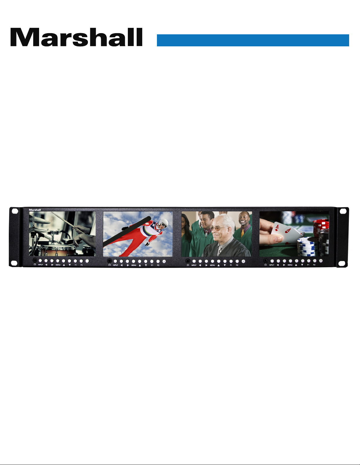
ML-454-V2
Quad 4.5” Rack Mount Monitor with
3G-SDI, HDMI and Composite Inputs
User Manual
Page 2

Table of Contents
1. Overview
2. Unpacking
3. Installation
4. Basic Operation
5. Menu Functions
6. Specifications
Warranty
02
02
02
04
06
09
10
1
Page 3

ML-454-V2 Manual
1. OVERVIEW
The ML-454-V2 provides four independent wide-screen displays in only 2RU rack height and very
slim 1.4” (35.8 mm) depth. Each display has inputs for 3GSDI, HDMI and standard composite
(CVBS) analog video sources. The SDI digital inputs provide active loop-through connections while
the composite input is self-terminating with passive loop-through.
Controls are conveniently placed on the front panel (computer not required). Menus are straightforward and intuitive. Front panel headphone jacks allow monitoring of embedded digital audio
(SDI and HDMI) as well as analog audio (for composite video AV input). On-screen three-color tally
borders operate from standard GPI connections (contact closure or open-collector pull-down) for
maximum compatibility with existing systems.
2. UNPACKING
Carefully unpack the ML-454-V2 monitor and verify the following items are included:
1. ML-454-V2 Monitor
2. 12 Volt Power supply with AC cord. ML-454PS
Inspect the unit for any physical damage that may have occurred during shipping. Should there be
any damage, immediately contact Marshall Electronics at (800) 800-6608. If you are not located
within the continental United States, call +1 (310) 333-0606.
3. INSTALLATION
The ML-454-V2 is designed to mount in a standard 19” equipment rack using the pre-installed
mounting ears. Once mounted, the monitor may be tilted to the ideal viewing position. Care should
be taken to allow sufficient slack in cables attached to the monitor so as not to bind when the
monitor is tilted. Also, check that the ventilation holes are not obstructed by other equipment in
the rack.
www.marshall-usa.com 2
Page 4
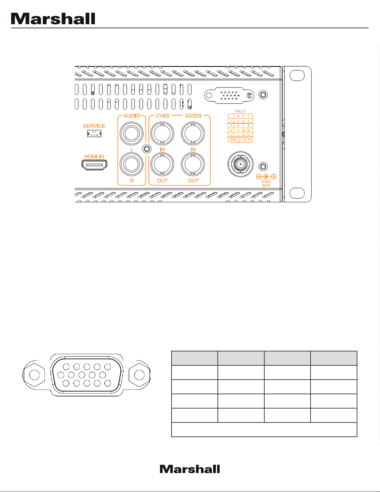
CONNECTIONS, POWER AND INITIAL SETUP
Note: Each screen has its own individual complement of video input connections.
Power and TALLY connections go to all screens
1. Power Connector
Connect the 12V DC input to the power input connector. Power can be supplied from the included
power supply, or from a variety of DC sources supplying at least 4.0 Amps at 12 Volts. (Average
power consumption 2.0 Amps at 12 Volts)
2. TALLY Connector
The tally border in each monitor is controlled by grounding the appropriate pin on the Tally connector
as shown in the table. Caution: External power should never be applied to the Tally connector.
(The Tally connector has the same “footprint” as a VGA connector.)
Tally
Screen #1
Screen #2
Screen #3
Screen #4
Green Border Red Border Yellow Border
1 2 3
6 7 8
11 12 13
5 10 15
GND 4, 9, 14
3
Page 5

ML-454-V2 Manual
Plug the included power supply into an AC power source (100 – 240 Volts @ 50/60 Hz). Attach the
power connector to the back of the monitor.
Connect the required cables for video signal input and output.
The monitor defaults to “ON” when power is connected. The Marshall name will first appear then
the video will be automatically detected and displayed on the screen. If the video does not appear,
press the INPUT button on the front panel to select an active source. SDI and CVBS inputs have
active loop through connections. Active loop-through does not work if main power is removed from
the monitor. Front power buttons have no effect on loop-through operation.
4. BASIC OPERATION
When main power is first applied to the ML-454-V2, the input selection defaults to the last used
source. To see other sources, press the Input button to cycle through three choices: HDMI, SDI and
AV (CVBS composite analog).
Headphone audio level may be adjusted by pressing the and buttons
menu pages are on screen.
The power button for each screen is located just above the headphone jack. The button lights up
green when the screen is ON.
To confirm that main power is being supplied to the internal components, a red LED light for each
screen is visible through the ventilation holes on top.
except when the
4
Page 6
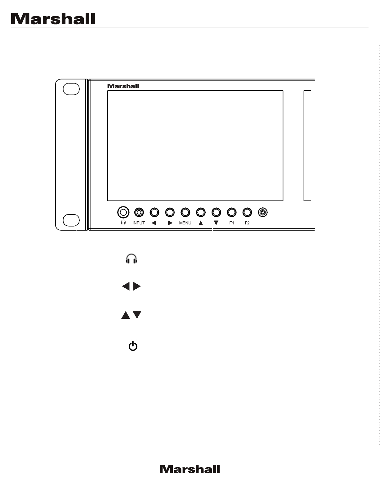
FRONT PANEL CONTROLS
– Headphone Jack
INPUT – Select HDMI, SDI, AV sources
eadphone Volume or Menu navigation
– H
MENU – Open / Back / Close the main menu window
– Menu Navigation
F1 & F2 – Turn User Programmed Function On/Off
– Power On/Off
5
Page 7
ML-454-V2 Manual
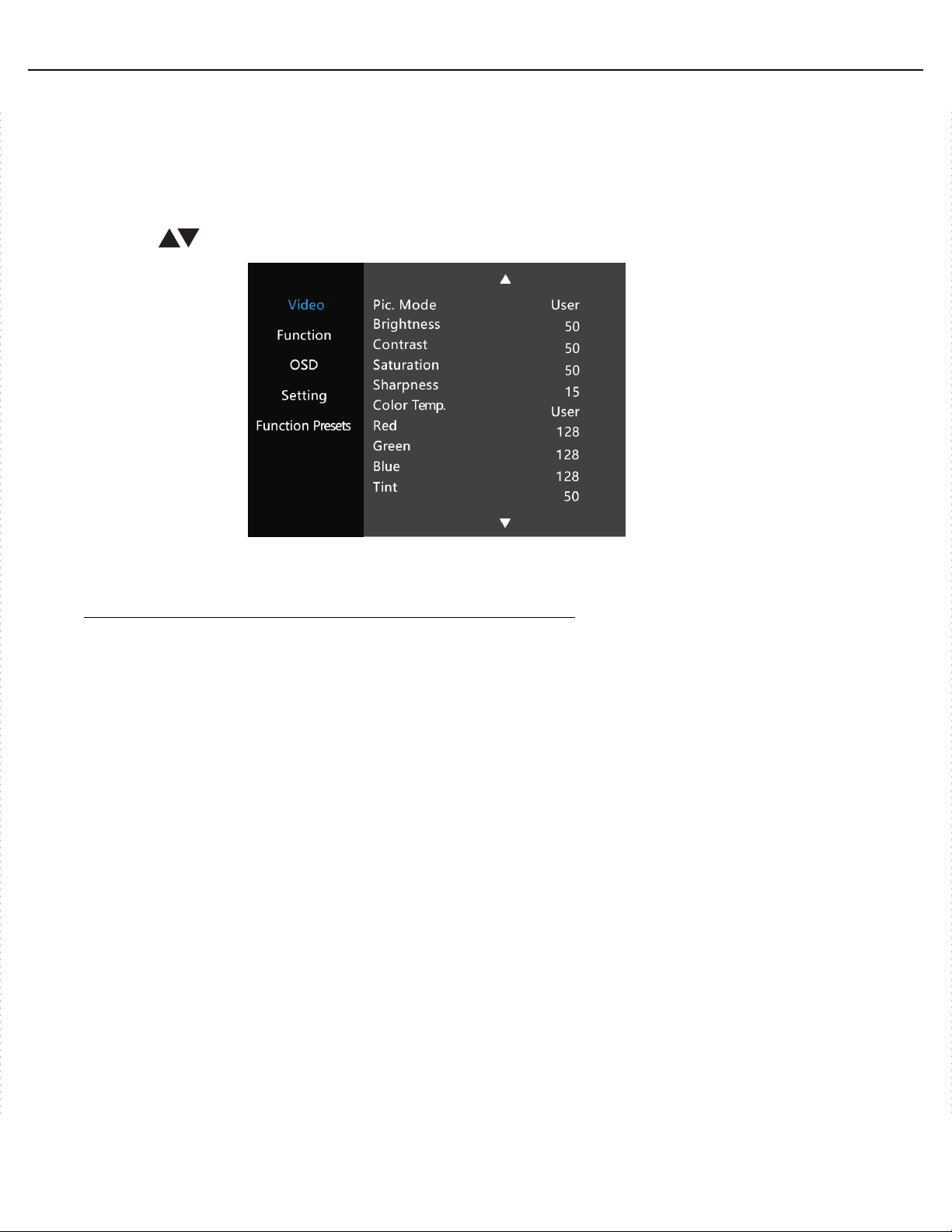
5. MENU FUNCTIONS
When the Menu button is pressed, a screen similar to this picture appears showing five
Main Menu categories.
Use the arrow buttons to move to the desired category.
1. Video
Adjust Appearance: chroma saturation, brightness, etc.
Pic. Mode: Select between three Presets and User setting.
Standard: Settings are in their mid-range.
Mild: Contrast and Saturation are reduced.
User: Brightness, Contrast, Saturation and Sharpness can be adjusted individually.
Dynamic: Contrast is boosted.
Color Temp: Select 6500, 9300 or User.
6500: Display white balance approximates 6500K (standard).
9300: Display white balance approximates 9300K (cool).
User: Red, Green and Blue gains may be adjusted to achieve the desired white balance.
Tint: Used to correct issues with
Tint is generally not applicable to digital video sources.
analog CVBS video sources
. All colors are affected.
www.marshall-usa.com
6
Page 8

2. Functions
Selecting On-Screen Markers;
Aspect Ratio, Image Flip, Peaking Filter and other Assistance Tools
Center Marker: Places a cross marker in the exact center of the image.
Safety Marker: Creates a border to indicate a safe area for camera framing
Adjustable from 80% to 96% and 2.35 wide aspect.
Marker Color: Select the high contrast marker color according to different image. Color choices are:
Red, Green, Blue, Black and White.
Check Field: Use the to display a single primary color or no color (monochrome).
Peaking Filter: This is a tool to assist setting sharp focus on a video camera. When this mode is
ON, the picture will be monochrome with a red border around objects in the image. As the camera
lens is adjusted, the red border will be brighter or dimmer. Brighter = sharper focus.
Aspect Ratio: Select the displayed aspect ratio to fit the source.
Full Screen: Picture is fit to just meet the edges of the display area.
Pixel to Pixel: Image pixels are mapped 1:1 to display pixels. (Scaling off). In most cases, this
will have the appearance of expanding the image.
4:3: Video is fit into a 4:3 window. This is a common setting for Standard Definition video.
16:9: Video is fit into a 16:9 window. This is the standard aspect ratio for HD video.
Image Flip: Flip the displayed image to compensate for special lenses or mirrors.
Image Freeze: Holds the current image on screen until Freeze is turned off.
Zoom All: Expands the picture on the screen in all directions by tapping the button
Default setting is“0”.
U/D Zoom: Expands the picture on screen vertically using the buttons.
L/R Zoom: Expands the picture on the screen horizontally using the buttons.
Scan Mode: Adjustable items are Standard & OverScan.
Overscan: allows checking the picture out to the edges.
7
Page 9

ML-454-V2 Manual
3. OSD
On-Screen Display Functions (menu position, etc.)
OSD Horizontal Position: Adjust horizontal position of Menus
OSD Vertical Position: Adjust vertical position of Menus
OSD Menu Transparency: Adjust the menu background
OSD Timeout: Set the number of seconds menu items will remain on the screen.
Input Format OSD: Signal format/frame rate display
4. Setting
Choose menu language, factory reset and upgrade mode
Language: Select the On-screen language for menus and messages.
Backlight: Adjust the brightness of screen backlight. Compensates for ambient lighting
Factory Reset: Press the button to set the display back to its original (default) state.
USB Upgrade: Initiate firmware update from a computer attached to the USB port.
5. Function Presets
Program the user Function buttons
User buttons allow the quick selection of a function without entering the menu system
F1 & F2: Use the and buttons to choose a function from this list:
Center Marker
Safety Marker
Marker Color
Check Field
Peaking Filter
Aspect Ratio
Image Flip
Image Freeze
Scan Mode
8
Page 10

6. SPECIFICATIONS
Panel size 4.46-inch TFT LCD
Resolution 1280 x RGB x 720
Backlight type LED, Adjustable Brightness
Dot pitch 0.0771mm x 0.0257mm
Aspect ratio
Panel Bit Depth True 8-bits (not dithered)
Brightness (cd/m²) 500
Contrast 1000:1
Viewing angles 80°/80°(L/R) 80°/80°(U/D)
Inputs HDMI / 3GSDI / CVBS / Audio(L/R)
Outputs 3GSDI / CVBS Loop Out
AV PAL - 4.43 / NTSC - 3.58
480i /480p /576i /576p (59.94/50)
HDMI
ITU-R BT.656 576i
SMPTE-125M 480i
720p (60/59.94/50/30/29.97/25/24/23.98)
1080i (60/59.94/50)
1080p (60/59.94/50/30/29.97/25/24/23.98)
16:9
3G-SDI
Earphone jack Stereo 3.5mm
Input voltage DC: 10~24 V (T
Power consumption 28 W (Typical)
Power Connector 5.5 mm x 2.1 mm locking coaxial
Dimensions
Weight
9
(main body) 3.53lbs, 1.6kg
SMPTE-274M
SMPTE-296M 720p (60/59.94/50/30/29/25/24/23.98)
SMPTE-424M 1080p (60/59.94/50)
19.0” W x 3.3” H x 1.4” D
482.5mm W x 84mm H x 35.8mm D
1080i (60/59.94/50)
1080p (30/29.97/25/24/23.98)
ypical 12 V)
Page 11

V.1. 2
 Loading...