

Page 1

M
G
15R
M
G
101F X
M
G
101F X
M
G
10 2FX
M
G
101F X
M
G
10 0HFX
M
G
10 2FX
OWNER’S MANUAL
Page 2

INTRODUCTION
WARNING! IMPORTANT SAFETY INSTRUCTIONS
Congratulaons on your purchase of this MG Gold amplier from Marshall Amplicaon.
The MG provides modern Marshall tones for the player who is on the go.
With your MG you can easily dial in storable sounds and eects including sparkling
clean, rich driven blues rock tone and heavy distorted metal sengs. Every element
from voicing through to the speaker has been carefully designed to give you exibility at
your ngerps.
From the punchy 10 wa to the powerful 100 wa, each MG Gold amplier is quick to
set-up and delivers me and me again. Whether you are praccing at home or gigging
on the road, the MG Gold not only looks good, it won’t let you down.
We hope you enjoy your MG Gold amplier.
- The Marshall Team
WARNING:
Before going any further, make sure that
your amplier is compable with your
mains electricity supply. If you have any
doubt, please seek help from a qualied
technician – your Marshall dealer can help
you in this respect.
MAINS INPUT & FUSE:
The specic mains input voltage rang
that your amplier has been manufactured
for is indicated on the rear panel of the
amplier. Your amplier is provided with
a detachable mains (power) lead, which
should be connected to the MAINS INPUT
socket on the rear panel of the amplier.
The correct value and type of mains fuse
is specied on the rear panel of each
amplier.
NEVER aempt to bypass the fuse or t one
of the incorrect value or type.
TRANSPORTING YOUR EQUIPMENT:
Please ensure that your amplier is
switched o, unplugged from the mains
electricity supply and that all removable
cables have been disconnected from your
equipment before aempng to move it.
IMPORTANT SET UP INFORMATION:
WARNING:
Failure to select the correct impedance
may damage your amplier.
If connecng a speaker cabinet make sure
that you use a proper speaker cable. Never
use a screened (shielded) guitar cable for
this purpose.
1. Ensure that the MAINS (power)
switch is set to the OFF posion.
2. Connect the supplied mains (power)
lead into the MAINS INPUT rst and
then into the mains electricity supply.
3. Ensure that the VOLUME controls on
the front panel are set to zero.
4. Plug your guitar into an INPUT jack
socket.
5. NEVER use MG100HFX without a
speaker cabinet connected.
6. Turn the front panel MAINS switch to
the ON posion.
7. Turn the VOLUME up to your
preferred level and your amplier is
ready to play.
ENGLISHENGLISH
Page 3

COMPLIANCE STATEMENT
This device complies with part 15 of the FCC Rules. Operaon is subject to the
following two condions:
1. This device may not cause harmful interference, and
2. This device must accept any interference received, including interference
that may cause undesired operaon.
This equipment has been tested and found to comply with the limits for a Class B
digital device, pursuant to part 15 of the FCC rules. These limits are designed to
provide reasonable protecon against harmful interference in a residenal
installaon.
This equipment generates, uses and can radiate radio frequency energy and, if not installed and used in accordance with the instrucons, may cause harmful
interference to radio communicaons.
However, there is no guarantee that interference will not occur in a parcular
installaon. If this equipment does cause harmful interference to radio or
television recepon, which can be determined by turning the equipment o and on, the
user is encouraged to try to correct the interference by one or more of the
following measures:
• Reorient or relocate the receiving antenna.
• Increase the separaon between the equipment and the receiver.
• Connect the equipment into an outlet on a circuit dierent from that to
which the receiver is connected.
• Consult the dealer or an experienced radio/TV technician for help.
CAUTION: Any changes or modicaons not expressly approved by the party
responsible for compliance could void the users authority to operate the equipment.
This device complies with CAN ICES-3(B)/NMB-3(B)
PLEASE READ THIS MANUAL CAREFULLY
BEFORE PLUGGING IN.
FOLLOW ALL INSTRUCTIONS AND HEED ALL WARNINGS.
KEEP THESE INSTRUCTIONS.
ENGLISH
Page 4

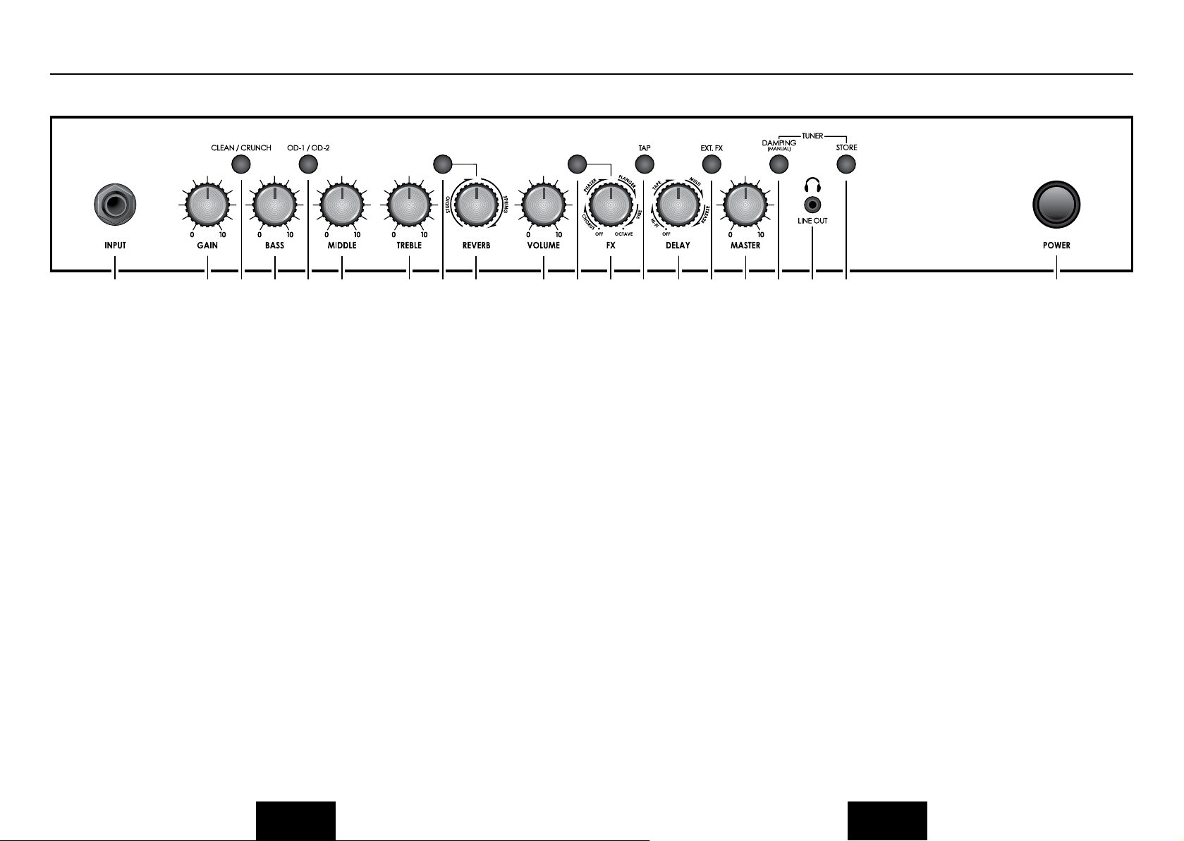
FRONT PANEL FUNCTIONS
1 5
42
1. INPUT JACK SOCKET
Input for your guitar. Use a good quality
guitar cable (i.e. one that’s screened/
shielded) to help prevent noise,
interference and unwanted feedback.
2. GAIN CONTROL
Controls the amount of signal entering
the pre-amp and the amount of distortion
created in the selected channel.
3. CLEAN/CRUNCH SWITCH
Selects between Clean (green) and Crunch
(red) channels.
4. BASS CONTROL
Adds warmth and low-end depth to your
sound.
5. OD-1/OD-2 SWITCH
Selects between OD-1 (green) and OD-2
(red) channels.
6. MIDDLE CONTROL
Varies the amount of body in your sound.
7. TREBLE CONTROL
Increasing the Treble will make your
sounds brighter and more cutting, turning
it down will decrease your tone’s edge and
make it sound softer as a result.
6
97
8. REV SWITCH
Switches the reverb effect on and off.
9. REVERB CONTROL
This control lets you add a lush digital
reverb to the selected channel, from a
subtle hint to cavernous and all points
in-between. Furthermore, there are two
distinctly different sounding reverb types
for you to choose from – Studio or Spring.
Studio emulates the sound of a studio
plate reverb while, as expected, Spring
emulates the sound of a classic spring
reverb unit.
10. VOLUME CONTROL
Controls the volume of the selected
channel.
11. FX SWITCH
Switches the FX section (FX and Delay) on
and off.
12. FX CONTROL
Selects and adjusts one of five digital
effects - Chorus, Phaser, Flanger, Vibe and
Octave.
13. TAP SWITCH
Matches the delay FX time to the time
between two pushes. The LED flashes at
selected delay time.
11 13
1210
14
1917 18
16
15
14. DELAY CONTROL
Controls the amount of signal sent to any
one of four selectable delay types – Hi-Fi,
Tape, Multi or Reverse.
15. EXT FX SWITCH
Switches the external FX Loop on and off.
16. MASTER CONTROL
Controls the master volume of the
amplifier.
17. DAMPING (MANUAL) SWITCH
Switches the power amp damping
between classic amp feeling (LED off)
and modern response (LED on). Holding
down the Damping switch for longer than
2 seconds switches the amp between
manual and preset mode.
When using the footcontroller, holding
both the Damping switch and the Store
switch will activate the tuner.
18. HEADPHONE / LINE OUT SOCKET
3.5mm headphones / Line out.
19. STORE SWITCH
Stores the current amp settings into
the current channel to recall with the
footcontroller. When in manual mode the
Store button lights red.
2083
20. POWER SWITCH
The power switch turns your amplifier
on and off. A channel switch will light up
when your amplifier is turned on and none
will be lit when the amplifier is switched
off.
ENGLISH
ENGLISH
Page 5

REAR PANEL FUNCTIONS
20 22
20. MAINS INPUT CONNECTOR
Your amp is provided with a detachable
mains (power) lead, which is connected
here. The specific mains input voltage
rating that your amplifier has been built
for is indicated on the back panel. Before
connecting for the first time, please
ensure that your amplifier is compatible
with your electricity supply. If you have
any doubt, please get advice from a
qualified technician. Your Marshall dealer
will help you in this respect.
The correct value of mains fuse located
in the small drawer at the bottom of the
mains socket is specified on the rear panel
of the amplifier. The drawer contains a
space for a spare fuse. NEVER attempt to
bypass the fuse or fit one of the incorrect
value!
21. FOOTCONTROLLER SOCKET
Jack socket for the connection of the
footcontroller.
22. LOUDSPEAKER OUTPUT(S) SOCKET
The MG101FX and MG102FX combos
have 1 loudspeaker output. The
MG100HFX head has 2 loudspeaker
outputs.
21
Always use a non-screened Marshall
approved speaker lead when connecting
an extension cabinet to these amplifiers.
23. MP3 LINE IN SOCKET
Jam to your favourite track by connecting
the line out or headphone output of your
player here. Adjust the volume of your
player to match that of your guitar and
you’ve got the perfect ‘play-along’ practice
system.
24. RETURN SOCKET
Connect to the output of an external
effects processor or pedal here.
25. SEND SOCKET
Connect to the input of an external effects
processor or pedal here.
23
24
25
ENGLISH ENGLISH
Page 6
OVERVIEW
CHANNEL SELECTION
The amplifier has 4 channels - Clean,
Crunch, OD1 & OD2.
Pressing the Clean/Crunch switch (3)
selects between the Clean (Green Light)
and Crunch (Red Light) channels.
Pressing the OD-1/OD-2 switch (5)
selects between the OD-1 (Green Light)
and OD-2 (Red Light) channels.
When moving from an OD channel
to a Clean/Crunch channel, the unit
remembers the last channel you were in
before leaving. E.g. If you have moved
from the Crunch Channel to an OD
channel and you press the Clean/Crunch
switch (3), the amplifier will revert back to
the Crunch channel - rather than starting
again in the Clean channel.
MODES
The amplifier operates in two modes Preset and Manual.
To change between these two modes, you
must hold the Damping switch (17) down
for at least two seconds. When in manual
mode the Store switch (19) lights red and
the selected channel light (3 or 5) will start
to flash.
The amplifier will remember the last mode
it was in after power off and revert to it
the next time it is powered on.
PRESET
This is the factory default operation of the
amplifier.
In Preset mode the position of all controls
except Master Volume (16) are stored
within each channel. Each channel should
be considered a preset.
Selecting a channel automatically recalls
the settings stored within the channel.
Note: The physical position of the front
panel controls, except Master Volume (16)
which is not storable, will now not match
the actual settings of the unit. All front
panel switches will automatically update.
Altering a control will cause the associated
parameter to jump to the current physical
position of that control.
When a control is altered the selected
channel light (3 or 5) will start to flash
indicating that the current preset has been
altered.
To store the updated settings, push the
Store switch (19).
If you select another channel without
pressing Store (19) then any altered
settings will be lost as the new channel
and its settings are recalled.
MANUAL
In manual mode the amps settings always
match the physical positions of the
controls.
Changing channel only changes the
channel, NO presets are recalled, NO
other controls are altered.
Pressing Store (19) will store the current
settings into the selected channel. These
can then be recalled when using the unit
in Preset mode.
When channel settings have been stored
the current channel light (3 or 5) will stop
flashing indicating the preset has been
saved.
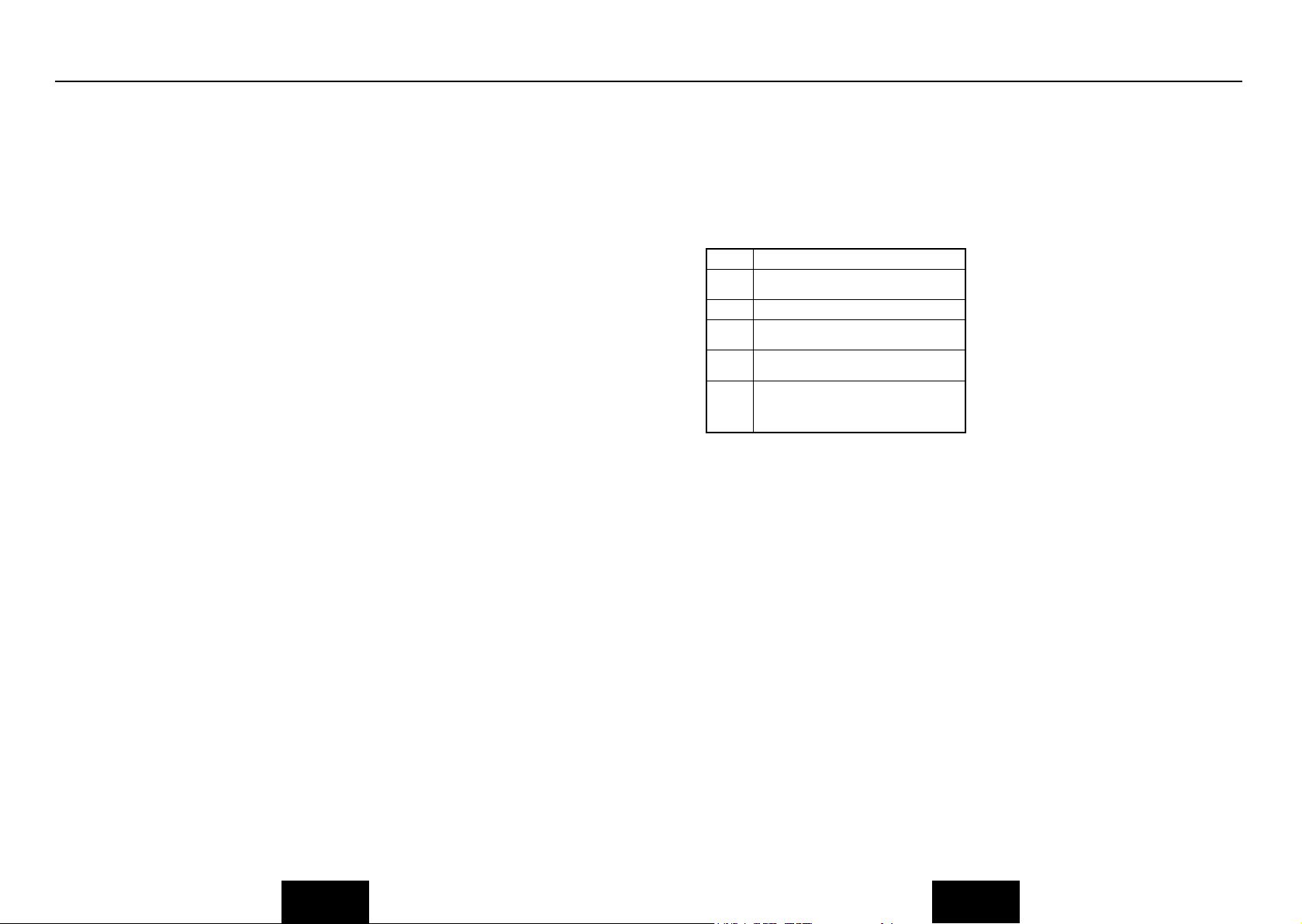
REVERB, FX & DELAY
The amplifier provides three simultaneous
digital effects: Reverb, Delay and any
one of the five offered on the FX control
(Chorus, Phaser, Flanger, Vibe or Octave).
REVERB
The Reverb control sets the amount of
signal sent to either one of the two reverb
options - Studio or Spring.
FX
The FX control is essentially split into five
segments and selects the type of FX and
adjusts its associated settings – except
in the case of Octave which has a single
setting. When the FX control is set to
‘0’ the FX are switched off, the status of
the FX is also indicated on the optional
footcontroller.
0 FX Off
Chorus Speed increases and depth is reduced as knob is
Phaser Speed increases as knob is turned clockwise.
Flanger Speed increases, feedback and depth are
Vibe The speed of the modulation increases as the
Octave When the FX control is turned fully clockwise
turned clockwise.
reduced as knob is turned clockwise.
control is turned clockwise.
the Octave effect is engaged – producing a
simultaneous note a full octave lower than the
one being played.
DELAY
Hi-Fi
A high fidelity, digital delay so pure that
each individual repeat is identical to the
original note(s).
Tape
This emulates the classic, analogue
nature of a tape echo, producing a warm,
dark sounding delay effect with each
successive repeat diminishing.
Multi
A digital delay with multiple outputs (taps),
each having a different delay time.
Reverse
As its name suggests, this emulates the
sound of a reverse or backwards delay –
usually created in a studio by reversing the
tape or track (i.e. playing it backwards).
TAP TEMPO
The Tap Tempo switch (13) is used for the
Delay effect only.
The Tap Tempo switch matches the delay
time to the time between two presses.
The Tap Tempo LED flashes red at the
selected/recalled delay time.
The number of repeats is reduced as the
delay time decreases. If you change from
a channel with delay to one without delay
the effect will spill between channels.
If you change from a channel with delay
to a channel with delay set to a different
delay time the delay effect will not spill
between channels.
MP3 / LINE IN
The 3.5mm MP3 / Line In socket (23) on
the rear panel allows the connection of
an external audio source e.g. MP3 or CD
player.
HEADPHONES & LINE OUT
The 3.5mm Headphone socket (18)
allows the connection of a pair of
headphones. When a jack is inserted into
the headphone socket the unit’s speaker
is muted.
Additionally the Headphone socket (18)
can also be used as a Line Out to send
the signal to an external equipment e.g.
A computer, digital recorder or mixer.
When a jack is inserted into the socket the
unit’s speaker is muted providing ‘silent
recording’. The unit’s output can then
be monitored directly from the external
equipment used.
DAMPING
The Damping switch (17) selects between
the two modes of power amp damping.
When Damping is off (LED off), the
power amp response resembles the feel
of a classic power amp with emphasised
middle and limited bass and treble.
Switching Damping on (LED on) will boost
the speaker resonances both in the bass
and high frequency ranges.
ENGLISH
ENGLISH
Page 7

OVERVIEW
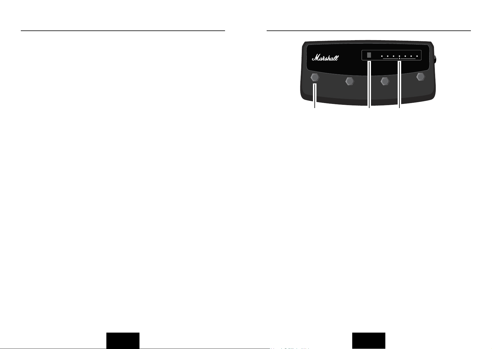
FOOTCONTROLLER STOMPWARE PEDL-90008 (OPTIONAL)
FX LOOP
The FX Return socket (24) on the rear
panel is used to connect the OUTPUT of
the effects processor or pedal you are
using in the effects loop.
The FX loop is series and set at instrument
level so both guitar FX or professional
rack effects units can be connected.
The FX Send socket (25) on the rear panel
is used to connect to the INPUT of the
unit you are using in the effects loop.
The FX loop is switched on and off via the
Ext FX switch (15) on the front panel.
LOUDSPEAKER
ALWAYS USE A NON-SCREENED
MARSHALL APPROVED SPEAKER LEAD
WHEN CONNECTING AN EXTENSION
CABINET TO THESE AMPLIFIERS.
MG101FX/MG102FX
The single Loudspeaker socket (22) is used
to connect either the internal speaker or
an external speaker cabinet to the unit’s
power amp. When using external cabinets
ensure the total load impedance is equal
to, or exceeds, 4 ohms.
MG100HFX
The two Loudspeaker sockets are used to
connect to 1 or 2 external cabinets. When
using external cabinets ensure the total
load impedance is equal to, or exceeds, 4
ohms.
POWER
The Power switch (20) turns the amplifier
on and off. If current settings have not
been stored they will be lost.
RESTORING SETTINGS - WARNING: ALL AMP
& FOOTSWITCH SETTINGS WILL BE LOST
To restore the unit to factory settings (see
handbook rear cover) you must hold the
Store switch (19) while powering on the
amplifier. The Clean/Crunch (3) and OD
(5) lights will light orange. You can then
release the Store switch (19).
Resetting the amplifier will erase all
user Channel presets and all user
Footcontroller allocations, replacing them
with the factory presets.
1
1
2
2
1 2 3
1. FOOTSWITCH
Each footswitch can be assigned a
different stored function.
2. DIGITAL DISPLAY
This display indicates the various
functions of the footcontroller.
3. LED STATUS PANEL
This always reflects the current status of
the amplifier or tuner details:
CLN & OD: Current Channel
REV: Reverb On/Off
FX: FX Section On / Off
Ext FX: External FX Loop On/Off
Damp: Damping Mode
Tap: Tap Tempo speed
FOOTCONTROLLER FACTORY SETTINGS
Footswitch 1: Clean/Crunch Switch
Footswitch 2: OD-1/OD-2 Switch
Footswitch 3: Tap Tempo Switch
Footswitch 4: Tuner
PROGRAMMING
The footswitch can be programmed to
store front panel switches (Switch Store)
or complete presets (Preset Store).
SWITCH STORE
To assign a front panel switch to a
Footswitch location (1), press and hold
the front panel switch and while held
CLN
OD REV FX EXT FX DAMP TAP
MG
Programmable
#
Footcontroller
- 50 + 50
Note / Preset
4
3
3
4
down press the Footswitch (1) you wish to
assign it to.
The Digital Display (2) will swirl to show
that the footswitch has been assigned.
You can then release the footswitch and
front panel switch.
PRESET STORE
To assign a preset to a Footswitch (1),
select the required channel and modify
the front panel controls if required, press
and hold the Store switch on the front
panel and while held down, press your
chosen Footswitch (1).
The Digital Display (2) will swirl to show
that the footswitch has been assigned.
You can then release the footswitch and
Store switch.
Footcontroller Presets are independent
of the dedicated Channel presets stored
within the amplifier. This allows you to
create a number of presets based on the
same channel/pre-amp setting.
When either a Channel preset or
Footswitch preset has been altered the
Digital Display (2) will begin to flash.
The footcontroller will flash the relevant
number if a Footswitch preset has been
altered or will flash a “-“ if a Channel
preset has been altered.
ENGLISH
ENGLISH
Page 8

FOOTCONTROLLER STOMPWARE PEDL-90008 (OPTIONAL) CONT. NOTES
Pressing only the Store switch at this
point will overwrite the altered Channel or
Footswitch preset.
To store an altered Channel preset to the
Footswitch instead, hold the Store switch
and while held down, press your chosen
Footswitch (1) - just like a normal Preset
Store.
To store an altered Footswitch Preset to
another Footswitch hold the Store switch
and while held down, press your chosen
Footswitch (1) - Just like a normal Preset
Store.
DIGITAL DISPLAY
When recalling a footswitch preset, the
Digital Display (2) will indicate which
footswitch number has been pressed.
If a Channel preset has been recalled the
Digital Display (2) will remain blank.
When either a Channel preset or
Footswitch preset has been altered the
Digital Display (2) will begin to flash. The
footswitch will flash the relevant number
if a Footswitch preset has been altered or
will flash a “-“ if a Channel preset has been
altered.
can then release the footswitch and front
panel switches.
FOR ALL AMPLIFIERS
When entering Tuner mode the unit
mutes and Clean/Crunch (3) and OD-1/
OD-2 (5) switches light yellow.
The Digital Display (2) indicates the
closest current note being played. The
indicator dot on the lower right hand
corner shows if the current closest note
is
♯.
The LED Status Panel (3) is used to show
how far away from the closest note the
current note being played is. When the
central FX Status LED lights, it indicates
the correct tuning, with the others
progressively indicating the tuning is up to
50 cents up or down.
To exit the Tuner push any footswitch,
the amplifier will then exit returning to the
settings before entering.
TUNER
The Tuner can be accessed in two ways:
By simultaneously pushing the Damping
(17) and Store (19) switches on the front
panel or by assigning the Tuner to the
footswitch. Note: On factory reset / first
switch on, the Tuner is already assigned to
Footswitch number 4.
Assigning the Tuner to a footswitch is
carried out like any other Switch Store.
To assign the Tuner to the footswitch
hold down the Damping (17) and Store
(19) switches and press the chosen
footswitch you wish to assign it to. The
Digital Display (2) will swirl to show that
the footswitch has been assigned. You
ENGLISH ENGLISH
Page 9

INTRODUCTION
AVERTISSEMENT ! CONSIGNES DE SÉCURITÉ IMPORTANTES
Félicitaons, vous venez d'acheter cet amplicateur MG Gold de la collecon
d'amplicaon Marshall.
Le MG ore des tons Marshall modernes à des musiciens qui ont la bougeoe.
Grâce au MG, vous pouvez facilement composer des tons et eets enregistrables,
notamment des réglages clean éclatants, des blues poussés riches en harmonies, des
tons rock et des tons métal à forte distorsion. Tous les composants, de la sonorisaon au
haut-parleur, ont été conçus avec soin pour vous orir un maximum de exibilité.
Du 10 wa punchy au puissant 100 wa, chaque amplicateur MG Gold est rapide à
installer et ent toutes ses promesses. Que ce soit en répèt' chez vous ou en concerts un
peu partout, le MG Gold n'est pas seulement beau, mais aussi d'une grande abilité.
Nous espérons que votre nouvel amplicateur MG Gold vous plaira.
- L'équipe Marshall
AVERTISSEMENT !
Avant d'aller plus loin, vérier que votre
amplicateur est compable avec votre
alimentaon électrique. En cas de doute,
s'adresser à un technicien qualié ; votre
vendeur Marshall est en mesure de vous
conseiller à ce sujet.
ENTRÉE SECTEUR ET FUSIBLE :
La tension nominale d'entrée spécique
correspondant à votre amplicateur
est indiquée sur le panneau arrière
de l'amplicateur. MG50FX: Votre
amplicateur est fourni avec un cordon
d'alimentaon détachable à brancher dans
la PRISE SECTEUR sur le panneau arrière
de l'amplicateur. Le type et la valeur
correcte des fusibles secteur sont indiqués
sur le panneau arrière de l'amplicateur.
NE JAMAIS tenter de dériver le fusible ou
d'installer un fusible dont le type ou la
valeur ne correspondent pas.
TRANSPORT DE VOTRE ÉQUIPEMENT :
Vérier que votre amplicateur est
éteint et débranché de l'alimentaon
secteur et que tous les câbles pouvant
être débranchés ont été déconnectés
de l'équipement avant de déplacer
l'amplicateur.
INFORMATIONS IMPORTANTES RELATIVES À
L'INSTALLATION :
AVERTISSEMENT !
Le non-respect de l'impédance correcte
risque d'endommager votre amplicateur.
Lors du raccordement d'un caisson hautparleur, veiller à uliser un câble pour
haut-parleur correct. Ne jamais uliser à
cet eet un câble de guitare blindé.
1. Vérier que le commutateur
d'ALIMENTATION est en posion
OFF.
2. Brancher le câble d'alimentaon
fourni à l'ENTRÉE ALIMENTATION
d'abord, puis sur la source
d'alimentaon électrique.
3. Vérier que les commandes du
VOLUME sur le panneau frontal sont
réglées sur zéro.
4. Brancher votre guitare dans la prise
jack d'ENTRÉE.
5. Ne JAMAIS uliser le MG100HFX
sans l’avoir branché à un caisson hautparleur.
FRANÇAIS
6. Régler l'interrupteur
d'ALIMENTATION sur MARCHE sur le
panneau avant.
7. Augmenter le VOLUME sur le niveau
souhaité : l'amplicateur est prêt.
FRANÇAIS
Page 10

DÉCLARATION DE CONFORMITÉ
Cet appareil est conforme à la pare 15 des Régulaons FCC.
L’exploitaon est autorisée aux deux condions suivantes :
1. Cet appareil ne doit pas produire de brouillage, et
2. L’appareil doit accepter tout brouillage radioélectrique subi, même si le
brouillage est suscepble d’en compromere le fonconnement.
Cet équipement a été testé et trouvé conforme aux limites applicables à un appareil
numérique de Classe B, suivant la Pare 15 des Règles FCC. Ces limites sont conçues
pour apporter une protecon raisonnable contre les interférences nuisibles dans un
environnement résidenel.
Cet équipement génère, ulise, et peut émere de l’énergie de fréquence radio et,
s’il n’est pas installé et ulisé conformément aux consignes, risque de causer des
interférences nuisibles aux communicaons radio.
Il n'existe toutefois aucune garane que ces interférences n'auront pas lieu dans
une installaon parculière. Si cet équipement cause des interférences nuisibles à la
récepon radiophonique ou télévisée, ce qui peut être établi en éteignant et rallumant
l'équipement, l'ulisateur est encouragé à prendre une plusieurs des mesures suivantes
pour résoudre ces interférences :
• Réorienter ou déplacer l'antenne de récepon.
• Augmenter la distance entre l'équipement et le récepteur.
• Brancher l'équipement dans une sore circuit diérente de celle dans laquelle
le récepteur est connecté.
• Demander l'aide de son revendeur ou d'un technicien radio/TV expérimenté.
MISE EN GARDE : Tout changement ou modicaon eectué sans avoir été
expressément approuvé par la pare responsable de sa conformité risque d'annuler le
droit d'exploitaon de l'équipement par son ulisateur.
Cet équipement est conforme aux normes CAN ICES-3(B)/NMB-3(B)
LIRE ATTENTIVEMENT CE MANUEL
AVANT DE BRANCHER L'ÉQUIPEMENT.
SUIVRE TOUTES LES INSTRUCTIONS ET TENIR COMPTE
DES AVERTISSEMENTS.
CONSERVER CES INSTRUCTIONS
FRANÇAIS
Page 11
FONCTIONS DU PANNEAU AVANT
1 5
42
1. PRISE JACK D'ENTRÉE
Prise jack d'entrée pour la guitare. Utiliser
un câble de guitare de bonne qualité (c'està-dire blindé) pour aider à limiter le bruit,
les interférences et la contre-réaction
indésirable.
2. COMMANDE DE GAIN
Contrôle la force du signal entrant dans le
préampli et le degré de distorsion créée sur
le canal sélectionné.
3. COMMUTATEUR CLEAN/CRUNCH
Bascule entre les canaux Clean (vert) et
Crunch (rouge).
4. CONTRÔLE DES GRAVES (BASS)
Ajoute de la chaleur et de la profondeur aux
basses du son.
5. COMMUTATEUR OD-1/OD-2
Bascule entre les canaux OD-1 (vert) et
OD-2 (rouge).
6. CONTRÔLE DES MÉDIUMS (MIDDLE)
Fait varier la quantité de corps du son.
7. CONTRÔLE DES AIGUS (TREBLE)
En augmentant les aigus, on obtient un
son plus vif et tranchant, tandis qu'en les
diminuant, on diminue la netteté tonale pour
un son plus doux.
6
97
8. COMMUTATEUR REV
Allume et éteint l'effet de reverb.
9. COMMANDE DE REVERB
Cette commande vous permet d'ajouter
une copieuse reverb numérique au canal
sélectionné, de la touche la plus subtile au
son le plus caverneux, en passant par toutes
les nuances. De plus, il existe deux types de
reverb aux sonorités clairement distinctes
à sélectionner : Studio ou Spring. Studio
reproduit le son d'une reverb à plaque de
studio, tandis que, comme le nom l'indique,
Spring reproduit le son d'un appareil de
reverb à ressort (spring) classique.
10. COMMANDE VOLUME
Règle le volume du canal sélectionné.
11. COMMUTATEUR FX (EFFET)
Allume et éteint la section FX (FX et Delay)
12. COMMANDE FX
Sélectionne et règle l'un des cinq effets
numériques : Chorus, Phaser, Flanger, Vibe
et Octave.
13. COMMUTATEUR TAP
Fait correspondre le temps de décalage
(delay) FX à l'intervalle entre deux pressions
de touche. Le voyant LED clignote à
l'intervalle de décalage sélectionné.
11 13
1210
14
1917 18
16
15
14. COMMANDE DÉCALAGE (DELAY)
Commande la force du signal envoyé à l'un
des quatre types de décalage disponibles :
Hi-Fi, Tape, Multi ou Reverse.
15. COMMUTATEUR FX (EFFET) EXTERNE
Allume et éteint la boucle FX externe.
16. COMMANDE MASTER
Contrôle le volume master de l'amplificateur.
17. COMMUTATEUR (MANUEL)
D'AMORTISSEMENT
Bascule l'amortissement de l'ampli de
puissance entre un ressenti d'ampli classique
(voyant LED éteint) et une réaction moderne
(voyant LED allumé). En maintenant le
commutateur d'amortissement enfoncé plus
de 2 secondes, on fait basculer l'ampli entre
les modes Manuel et Préréglage.
En cas d'utilisation d'une pédale, on active
l'accordeur en maintenant simultanément
enfoncés le commutateur d'amortissement
et le commutateur de mémorisation.
18. PRISE CASQUE / SORTIE DE LIGNE
Casque / Sortie de ligne 3,5 mm.
2083
19. COMMUTATEUR DE MÉMORISATION
Mémorise les paramètres actuels de
l'ampli sur le canal activé, pour qu'ils soient
récupérables via la pédale. En mode manuel,
le bouton Mémoriser s'allume en rouge.
20. COMMUTATEUR D'ALIMENTATION
L'interrupteur d'alimentation allume et éteint
votre amplificateur. Un commutateur de
canaux s'allume quand votre amplificateur
est allumé, et aucun ne s'allume si
l'amplificateur est éteint.
FRANÇAIS
FRANÇAIS
Page 12

FONCTIONS DU PANNEAU ARRIÈRE
20 22
20. CONNECTEUR D'ENTRÉE SECTEUR
Votre ampli est livré avec un cordon
d'alimentation détachable, qui se branche
ici. La tension nominale d'entrée spécifique
correspondant à votre amplificateur est
indiquée sur le panneau arrière. Avant
de brancher l'ampli pour la première fois,
vérifier que l'amplificateur est compatible
avec l'alimentation électrique. En cas de
doute, demander conseil à une personne
qualifiée. Votre vendeur Marshall est en
mesure de vous aider à ce sujet.
La valeur correcte du fusible secteur situé
dans le petit tiroir au bas de la prise secteur
est indiquée sur le panneau arrière de
l'amplificateur. Le tiroir est assez grand pour
contenir un fusible de rechange. NE JAMAIS
tenter de dériver le fusible ou d'installer un
fusible dont la valeur ne correspond pas !
21. PRISE PÉDALE
Prise jack pour le raccordement de la pédale.
22. PRISE DE SORTIE(S) HAUT-PARLEUR
Les combos MG101FX et MG102FX ont 1
sortie pour baffle. La tête MG100HFX a 2
sorties pour baffle.
21
23. PRISE D'ENTRÉE DE LIGNE MP3
Pour jouer sur vos morceaux préférés sur
MP3, CD ou cassette, raccorder la sortie
casque ou la sortie de ligne de votre lecteur
ici. Régler le volume de votre lecteur en
fonction de celui de votre guitare : le parfait
système de répèt' accompagnée, en un tour
de main.
24. PRISE RETOUR (RETURN)
Raccorder la sortie d'un processeur d'effets
externe ou d'une pédale ici.
25. PRISE ENVOI (SEND)
Raccorder l'entrée d'un processeur d'effets
externe ou d'une pédale ici.
23
24
25
t
oujours utiliser un câble haut-parleur non
blindé approuvé par Marshall pour raccorder
un caisson d'extension à ces amplificateurs.
FRANÇAIS
FRANÇAIS
Page 13

PRÉSENTATION D'ENSEMBLE
SÉLECTION DE CANAL
L'amplificateur possède 4 canaux - Clean,
Crunch, OD1 & OD2.
En appuyant sur le commutateur de canaux
Clean/Crunch (3), on bascule entre le canal
Clean (voyant vert) et le canal Crunch (voyant
rouge).
En appuyant sur le commutateur de canaux
OD-1/OD-2 (5), on bascule entre le canal
Clean (voyant vert) et le canal Crunch (voyant
rouge).
Lors du basculement d'un canal OD à un canal
Clean/Crunch, l'appareil se rappelle du dernier
canal utilisé avant d'arrêter. Par ex., si vous
êtes passé du canal Crunch à un canal OD et
que vous appuyez sur le commutateur Clean/
Crunch (3), l'amplificateur repasse sur le canal
Crunch, plutôt que d'activer le canal Clean.
MODES
L'amplificateur fonctionne sur deux modes :
Preset (Préréglage) et Manual (Manuel).
Pour basculer entre ces deux modes, il faut
maintenir le commutateur d'amortissement
(damping - 17) enfoncé pendant au moins
deux secondes. En mode manuel, le
commutateur Mémoriser (19) s'allume en
rouge, et le voyant du canal sélectionné (3 ou
5) s'allume en rouge.
L'amplificateur mémorise le dernier mode
sur lequel il était réglé avant d'être éteint, et
reprend ce mode au démarrage suivant.
PRÉRÉGLAGE
Il s'agit du fonctionnement d'usine par défaut
de l'amplificateur.
En mode Préréglage, la position de toutes
les commandes sauf Master Volume (16) est
mémorisée pour chaque canal. Chaque canal
peut être considéré comme un préréglage.
Le canal choisi récupère automatiquement
les paramètres mémorisés dans ce canal.
Remarque : La position physique des
commandes du panneau avant, sauf pour le
volume Master (16) qui n'est pas mémorisable,
ne correspondront plus aux paramètres
actuels de l'appareil. Tous les commutateurs
du panneau avant se mettent à jour
automatiquement.
La modification d'une commande se traduit
par le passage du paramètre associé sur
la position physique actuelle de cette
commande.
Lorsqu'une commande est modifiée, le voyant
du canal sélectionné (3 ou 5) se met à clignoter
pour indiquer que le préréglage actuel a été
modifié.
Pour mémoriser les paramètres mis à jour,
appuyer sur le commutateur de
mémorisation (19).
Si vous choisissez un autre canal sans
avoir appuyé sur Mémoriser (19), tous
les paramètres modifiés seront perdus à
l'activation des paramètres du nouveau canal.
MANUEL
En mode manuel, les paramètres de l'ampli
correspondent toujours aux positions
physiques des commandes.
Lorsqu'on change de canal, on ne change que
le canal ; AUCUN préréglage n'est récupéré,
AUCUNE autre commande n'est modifiée.
En appuyant sur Mémoriser (19), on
mémorise les paramètres actuels dans le canal
sélectionné. Ces paramètres peuvent être
récupérés lorsqu'on utilise l'appareil en mode
Préréglage.
Une fois les paramètres du canal mémorisés,
le voyant du canal actuel (3 ou 5) cesse de
clignoter, indiquant ainsi que le préréglage a
été enregistré.
REVERB, FX & DELAY
L'amplificateur propose trois effets
numériques simultanés : Reverb, Delay et l'un
des cinq effets proposés par la commande FX
(Chorus, Phaser, Flanger, Vibe ou Octave).
REVERB
La commande reverb règle la force du signal
numérique envoyé à l'une des deux options de
reverb : Studio ou Spring.
FX
La commande FX est divisée en cinq segments ;
elle sélectionne le type d'effet et règle les
paramètres associés, à l'exception d'Octave,
qui possède un paramètre unique. Lorsque la
commande FX est réglée sur '0', les effets sont
éteints ; l'état des effets est aussi indiqué sur la
pédale optionnelle.
0 FX éteint
Chorus La vitesse augmente et la profondeur est réduite
Phaser La vitesse augmente si l'on tourne le bouton
Flanger La vitesse augmente, la contre-réaction et la
Vibe La modulación aumenta de velocidad a medida
Octave Lorsque la commande FX est tournée à fond
si l'on tourne le bouton dans le sens horaire.
dans le sens horaire.
profondeur sont réduites si l'on tourne le bouton
dans le sens horaire.
que el control se gira en sentido horario.
dans le sens horaire, l'effet Octave est activé :
cela produit une note simultanée plus grave
d'une octave complète que celle qui est jouée.
DELAY
Hi-Fi
Un décalage numérique haute fidélité tellement
pur que chacune des répétitions reste identique
la / les note(s) originale(s).
Cassette
Reproduit la nature d'un écho cassette classique,
analogique, pour produire un effet de décalage
chaleureux, à résonance sombre, dont chaque
répétition successive diminue progressivement.
Multi
Un décalage numérique à nombreuses sorties
(taps), possédant chacune un temps de décalage
différent.
Reverse (Sens inverse)
Comme son nom l'indique, cet effet reproduit le
son d'un décalage en sens inverse ou en arrière,
habituellement créé en studio par l'inversion
d'une cassette ou d'un morceau (c'est-à-dire en
le jouant à l'envers).
TAP TEMPO
Le commutateur Tap Tempo (13) n'est utilisé
que pour l'effet Delay.
Le commutateur Tap Tempo fait correspondre
le temps de décalage (Delay) entre deux
pressions de touche.
Le voyant LED Tap Tempo clignote à
l'intervalle de décalage sélectionné / récupéré.
Le nombre de répétitions est réduit à mesure
que diminue le décalage. Si vous passez d'un
canal avec décalage à un canal sans décalage,
l'effet se propage d'un canal à l'autre.
Si vous d'un canal avec décalage à un autre
canal avec décalage réglé sur un décalage
différent, l'effet de décalage ne se propage pas
entre les canaux.
MP3 / ENTRÉE DE LIGNE
La prise MP3 / Entrée de ligne 3,5 mm (23)
sur le panneau arrière permet le raccordement
d'une source audio externe, par ex. lecteur CD
ou MP3.
CASQUE & SORTIE DE LIGNE
La prise casque 3,5 mm (18) permet le
raccordement d'un casque. Lorsqu'un jack est
inséré dans la prise casque, le haut-parleur de
l'appareil est rendu silencieux.
En outre, la prise casque (18) peut aussi servir
de sortie de ligne pour envoyer le signal vers
un équipement externe comme un ordinateur,
un enregistreur numérique ou un mélangeur.
Lorsqu'un jack est inséré dans la prise, le
haut-parleur de l'appareil est rendu silencieux
pour un "enregistrement silencieux". La
sortie de l'appareil peut alors être supervisée
directement à partir de l'équipement externe
utilisé.
AMORTISSEMENT
Le commutateur d'amortissement (17) bascule
entre deux modes d'amortissement de l'ampli
FRANÇAIS
FRANÇAIS
Page 14
PRÉSENTATION D'ENSEMBLE
PÉDALE STOMPWARE PEDL-90008 (OPTIONELLE)
de puissance. Lorsque l'amortissement est
éteint (voyant LED éteint), l'ampli de puissance
évoque le ressenti d'un ampli de puissance
classique, avec des médiums accentués, tandis
que les graves et les aigus sont limités. En
activant l'amortissement (voyant LED allumé),
on booste les résonances du haut-parleur sur
les gammes de fréquences graves et aiguës.
BOUCLE FX
La prise retour FX (24) sur le panneau arrière
sert à connecter la SORTIE du processeur
d'effets ou de la pédale utilisé(e) sur la boucle
d'effets (FX).
La boucle d'effets est en série et réglable
au niveau de l'instrument, on peut donc
connecter à la fois les effets de guitare ou des
appareils d'effets en rack professionnels.
La prise envoi FX (25) sur le panneau arrière
sert à se connecter à l'ENTRÉE de l'appareil
utilisé sur la boucle d'effets (FX).
La boucle d'effets est actionnable via le
commutateur FX externe (15) sur le panneau
avant.
HAUT-PARLEUR
TOUJOURS UTILISER UN CÂBLE HAUTPARLEUR NON BLINDÉ APPROUVÉ
PAR MARSHALL POUR RACCORDER
UN CAISSON D'EXTENSION À CES
AMPLIFICATEURS.
COMBOS MG101FX ET MG102FX
L’unique prise pour baffle (22) sert à
brancher à l’amplificateur de puissance
de l’unité soit le haut-parleur interne soit
un baffle externe. Quand vous employez
des baffles externes, veillez à ce que
l’impédance de charge totale soit égale ou
supérieure à 4 ohms.
TÊTE MG100HFX
Les deux prises pour baffle servent à
brancher 1 ou 2 baffles externes. Quand
vous employez des baffles externes,
veillez à ce que l’impédance de charge
totale soit égale ou supérieure à 4 ohms.
RÉTABLIR LES PARAMÈTRES : MISE EN GARDE :
TOUS LES RÉGLAGES DE L'AMPLI ET DE LA
PÉDALE SONT PERDUS
Pour rétablir les paramètres d'usine de
l'appareil (cf dos du manuel), il faut maintenir
enfoncé le commutateur de mémorisation
(19) tout en allumant l'amplificateur. Les
voyants Clean/Crunch (3) et OD (5) s'allument
en orange. Vous pouvez alors relâcher le
commutateur de mémorisation (19).
En réinitialisant l'amplificateur, on efface
tous les préréglages de canaux effectués par
l'utilisateur, et tous les réglages de la pédale,
pour les remplacer par les préréglages d'usine.
1
1
2
2
1 2 3
1. PÉDALIER
On peut assigner à chaque pédalier une fonction
différente.
2. ÉCRAN NUMÉRIQUE
Cet écran indique les diverses fonctions de la
pédale.
3. PANNEAU DES VOYANTS LED DE STATUT
Il reflète toujours le statut actuel de l'amplificateur
ou des détails de l'accordeur :
CLN & OD: Canal actuel
REV: Reverb Marche / Arrêt
FX: Section FX Marche / Arrêt
Ext FX: Boucle FX externe Marche / Arrêt
(MG50FX)
Damp: Mode amortissement (MG50FX)
Tap: Vitesse Tap Tempo
PARAMÈTRES D'USINE DE LA PÉDALE
Pédalier 1 : Commutateur Clean/Crunch
Pédalier 2 : Commutateur OD-1/OD-2
Pédalier 3 : Commutateur Tap Tempo
Pédalier 4 : Accordeur
PROGRAMMATION
Le pédalier peut être programmé pour mémoriser
les commutateurs du panneau avant (Mémorisation
des commutateurs - Switch Store) ou l'intégralité
des préréglages (Preset Store).
CLN
OD REV FX EXT FX DAMP TAP
MG
Programmable
#
Footcontroller
- 50 + 50
Note / Preset
4
3
3
MODE MÉMORISATION DES COMMUTATEURS
(SWITCH STORE)
Pour assigner un commutateur du panneau avant à
un emplacement de pédalier (1), maintenir enfoncé
le commutateur de panneau avant concerné tout
en appuyant sur le Pédalier (1) auquel vous voulez
l'assigner.
L'écran numérique (2) affiche un tourbillon pour
indiquer que l'assignation du pédalier a été
effectuée. On peut alors relâcher le pédalier et le
commutateur du panneau avant.
MÉMORISATION DES PRÉRÉGLAGES
Pour assigner un commutateur du panneau avant
à un emplacement de pédalier (1), sélectionner le
canal requis et modifier les commandes du panneau
avant, le cas échéant, puis maintenir enfoncé le
commutateur de mémorisation du panneau avant
tout en appuyant sur le Pédalier (1) auquel vous
voulez l'assigner.
L'écran numérique (2) affiche un tourbillon pour
indiquer que l'assignation du pédalier a été
effectuée. On peut alors relâcher le pédalier et le
commutateur de mémorisation.
Les préréglages de la pédale fonctionnent
indépendamment des préréglages du canal dédié
mémorisés dans l'amplificateur. C'est ce qui vous
permet de créer divers préréglages basés sur le
même réglage de préampli / canal.
Lorsqu'un préréglage de canal ou un préréglage de
pédalier est modifié, l'écran numérique (2) se met à
4
FRANÇAIS
FRANÇAIS
Page 15

PÉDALE STOMPWARE PEDL-90008 (OPTIONELLE - SUITE)
REMARQUES
clignoter. La pédale affiche en clignotant le numéro
concerné si un préréglage de pédalier est modifié,
ou un "-" si c'est un préréglage de canal qui a été
modifié.
En n'appuyant alors que sur le commutateur de
mémorisation, on efface le préréglage de canal ou
de pédalier qui a été modifié.
Pour mémoriser un préréglage de canal sur
le pédalier, maintenir le commutateur de
mémorisation enfoncé, et appuyer simultanément
sur le pédalier de votre choix (1) : exactement
comme pour une mémorisation de préréglage
normale.
Pour mémoriser un préréglage de pédalier modifié
sur un autre pédalier, maintenir le commutateur de
mémorisation enfoncé, et appuyer simultanément
sur le pédalier de votre choix (1) : exactement
comme pour une mémorisation de préréglage
normale.
AFFICHAGE NUMÉRIQUE
Lorsqu'on active un préréglage de pédalier, l'écran
numérique (2) indique sur quel numéro de pédalier
on a appuyé.
Si un préréglage de canal est activé, l'écran
numérique (2) n'affiche rien.
ACCORDEUR
On peut accéder à l’accordeur de deux manières :
En appuyant simultanément sur les commutateurs
Amortissement
le panneau avant, ou en assignant l’accordeur à
un pédalier. Remarque : Après une réinitialisation
d’usine, ou lors du premier démarrage, l’accordeur
est déjà assigné au pédalier numéro 4.
Ou, en assignant l’accordeur à un pédalier. Cela
s’effectue comme n’importe quelle mémorisation
de commutateur. Pour assigner l’accordeur
à un pédalier, maintenir les commutateurs
Amortissement
enfoncés et appuyer sur le pédalier auquel vous
souhaitez l’assigner. L’écran numérique (2) affiche
un tourbillon pour indiquer que l’assignation du
pédalier a été effectuée. On peut alors relâcher le
pédalier et le commutateur du panneau avant.
POUR TOUS LES AMPLIFICATEURS
Lorsqu'on active le mode Accordeur, le son de
l'appareil est coupé et les commutateurs Clean/
Crunch (3) et OD-1/OD-2 (5) s'allument en jaune.
L'écran numérique (2) indique la note la plus proche
de celle qui est jouée. Le point d'indication dans
le coin en bas à droite s'affiche si la note la plus
proche de celle jouée est en ♯.
(17) et Mémorisation (19) sur
(17) et Mémorisation (19)
Lorsqu'un préréglage de canal ou un préréglage
de pédalier est modifié, l'écran numérique (3) se
met à clignoter. Le pédalier affiche en clignotant le
numéro concerné si un préréglage de pédalier est
modifié, ou un "-" si c'est un préréglage de canal qui
a été modifié.
FRANÇAIS FRANÇAIS
Le panneau des voyants LED (3) de statut sert
à montrer la distance qui sépare la note la plus
proche de celle jouée. Lors que le voyant LED de
statut FX s'allume, cela indique l'accord correct,
tandis que les autres indiquent progressivement
que l'accord est jusqu'à 50 % au-dessus ou endessous.
Pour quitter l'accordeur, appuyer sur n'importe quel
pédalier : l'amplificateur quitte alors l'accordeur et
revient aux paramètres avant activation.
Page 16

EINLEITUNG
WARNUNG! WICHTIGE SICHERHEITSHINWEISE
Herzlichen Glückwunsch zum Kauf dieses MG Gold Verstärkers von Marshall
Amplicaon.
Der MG bietet modernen Marshall-Klang für Musiker unterwegs.
Mit Ihrem MG können Sie ganz einfach unter speicherbaren Klängen und Eekten z.B.
einen kristallklarem Blues sae Rock-Sounds oder verzerrte Heavy-Metal-Einstellungen
auswählen. Jedes Element, von der Sprachwiedergabe bis zu den Lautsprechern, wurde
sorgfälg auf exible und einfache Bedienung ausgelegt.
Vom schlagkräigen 10 wa bis zum leistungsstarken 100 wa ist jeder MG Gold
Verstärker schnell einzurichten und spart jedesmal Zeit. Ob Sie zu Hause üben oder auf
der Straße spielen, der MG Gold sieht nicht nur gut aus, es wird Sie auch nicht im Sch
lassen.
Wir hoen, dass Sie viel Freude mit Ihrem neuen MG Gold Verstärker haben werden.
- Ihr Marshall-Team
WARNHINWEIS:
Versichern Sie sich, bevor Sie forahren,
dass der Verstärker mit dem Stromnetz
kompabel ist. Bei Unklarheiten ist ein
Fachmann aufzusuchen – der MarshallHändler kann dabei helfen.
NETZSPANNUNG UND SICHERUNG:
Die spezische Netzeingangsspannung,
für die Ihr Verstärker gebaut wurde, ist auf
der Rückseite des Verstärkers angegeben.
MG50FX: Der Verstärker wird mit einem
separaten Netzkabel geliefert, das an
die NETZEINGANGSBUCHSE auf der
Rückseite des Verstärkers anzuschließen
ist. Der korrekte Wert und das korrekte
Modell der Netzsicherung werden auf der
Rückseite des Verstärkers angegeben.
ES DARF NIEMALS versucht werden, die
Sicherung zu überbrücken oder eine
Sicherung eines unzulässigen Werts oder
Modells einzusetzen.
TRANSPORT DER GERÄTE:
Vor dem Transport ist sicherzustellen,
dass der Verstärker ausgeschaltet und
nicht ans Stromnetz angeschlossen ist und
dass die enernbaren Kabel nicht an das
Equipment angeschlossen sind.
WICHTIGE INFORMATIONEN ZUM AUFBAU:
WARNHINWEIS:
Wenn die falsche Impedanz ausgewählt
wird, kann dies zur Beschädigung Ihres
Verstärkers führen.
Beim Anschluss einer Lautsprecherbox
ist sicherzustellen, dass das richge
Lautsprecherkabel verwendet wird.
Verwenden Sie zu diesem Zweck niemals
ein geschirmtes Gitarrenkabel.
1. Stellen Sie sicher, dass sich der NETZSchalter (Power) in der Posion OFF
bendet.
2. Schließen Sie das mitgelieferte
Netzkabel zuerst in den
NETZEINGANG und danach an das
Stromnetz an.
3. Achten Sie darauf, dass die
LAUTSTÄRKE-Regler an der
Vorderseite auf Null gestellt sind.
4. Schließen Sie Ihre Gitarre an die
INPUT (Eingangs)-Klinkenbuchse an.
5. Verwenden Sie MG100HFX NIE ohne
angeschlossene Lautsprecherbox.
DEUTSCH
6. Bringen Sie den NETZSCHALTER auf
der Vorderseite in die Posion ON.
7. Stellen Sie die LAUTSTÄRKE wie
gewünscht ein und Ihr Verstärker ist
spielbereit.
DEUTSCH
Page 17

KONFORMITÄTSERKLÄRUNG
Dieses Gerät entspricht den Besmmungen von Teil 15 der FCC-Vorschrien.
Die folgenden zwei Bedingungen sind Voraussetzungen für den Betrieb:
1. Das Gerät darf keine schädlichen Störungen verursachen und
2. Das Gerät muss jeglichen Störungen, die das Gerät erreichen, standhalten,
auch Störungen, die sich auf unerwünschte Weise auf den Betrieb auswirken.
Dieses Gerät wurde getestet und entspricht den Grenzwerten für digitale Geräte der
Klasse B gemäß Teil 15 der FCC-Vorschrien. Diese Grenzwerte sind so ausgelegt,
dass sie einen angemessenen Schutz gegen schädliche Störungen in einer Wohnanlage
bieten.
Dieses Gerät erzeugt und nutzt Funkfrequenzenergie und kann solche abstrahlen und
beeinträchgt möglicherweise die Funkkommunikaon, wenn es nicht gemäß den
Anweisungen installiert und benutzt wird.
Es gibt allerdings keine Garane dafür, dass es bei einer besmmten Installaon
zu keiner Störung kommt. Falls dieses Gerät beim Radio- oder Fernsehempfang
Funkstörungen verursacht, was Sie feststellen können, indem Sie das Gerät aus- und
wieder einschalten, sollte der Anwender diese Störungen durch eine oder mehrere der
folgenden Maßnahmen beseigen:
• Neue Ausrichtung oder Posionierung der Empfangsantenne
• Vergrößern des Abstands zwischen Gerät und Empfänger
• Anschluss des Geräts an eine Steckdose, an deren Stromkreis nicht auch
der Empfänger angeschlossen ist.
• Hinzuziehen des Händlers oder eines erfahrenen Radio-/Fernsehtechnikers.
VORSICHT: Jegliche Änderungen oder Modikaonen dieses Geräts, die nicht
ausdrücklich durch die für die Einhaltung der Vorschrien zuständige Partei genehmigt
sind, können zum Erlöschen der Berechgung des Nutzers zum Betreiben des Geräts
führen.
Dieses Gerät entspricht CAN ICES-3(B)/NMB-3(B)
LESEN SIE DIESES HANDBUCH SORGFÄLTIG DURCH,
BEVOR SIE DAS GERÄT ANSCHLIESSEN.
ALLE ANWEISUNGEN EINHALTEN UND ALLE WARNUNGEN
BEACHTEN.
DIESE ANWEISUNGEN AUFBEWAHREN!
DEUTSCH
Page 18

FUNKTIONEN VORDERSEITE
1 5
42
1. INPUT KLINKENBUCHSE
Eingangsbuchse für Ihre Gitarre. Verwenden
Sie ein hochwertiges Gitarrenkabel (d.h.
ein abgeschirmtes), um Lärm, Störungen
und unerwünschte Rückkopplungen zu
vermeiden.
2. GAIN-REGLER
Steuert die Signalstärke, die in den
Vorverstärker eingeht und die Verzerrung,
die im ausgewählten Kanal erzeugt wird.
3. CLEAN/CRUNCH UMSCHALTER
Schaltet zwischen Clean-Kanal (grün) und
Crunch-Kanal (rot) um.
4. BASSREGLER (BASS)
Bringt Wärme und Tiefe in Ihren Klang.
5. OD-1/OD-2 UMSCHALTER
Schaltet zwischen OD-1-Kanal (grün) und
OD-2-Kanal (rot) um.
6. MITTENREGLER (MIDDLE)
Verändert den Body-Anteil in Ihrem Klang.
7. HÖHENREGLER (TREBLE)
Mehr Höhen machen Ihren Klang heller
und schärfer, weniger Höhen schneiden die
oberen Frequenzen ab machen den Klang
weicher.
6
97
8. HALL-SCHALTER
Schaltet den Halleffekt ein und aus.
9. HALLREGLER (REVERB)
Mit diesem Regler können Sie dem
ausgewählten Kanal einen üppigen digitalen
Hall hinzufügen, von einem leichten Hauch
bis hin zu riesigen Hallen. Darüber hinaus
können Sie zwischen zwei unterschiedlich
klingenden Hallarten wählen - Studio oder
Spring. Studio simuliert den Klang in einem
schallisolierten Studio, während Spring, wie
der Name bereits verrät, für konventionellen
Spring-Reverb steht.
10. LAUTSTÄRKEREGLER
Mit diesem Regler wird die Lautstärke des
ausgewählten Kanals eingestellt.
11. FX-SCHALTER
Schaltet den FX-Bereich (FX und Delay) ein
und aus.
12. FX REGLER
Dient zu Auswahl und Einstellung der fünf
Digitaleffekte - Chorus, Phaser, Flanger, Vibe
und Octave.
13. TAP-SCHALTER
Passt die FX-Verzögerungszeit der Zeit
zwischen zwei Betätigungen an. Die LED
blinkt zur gewählten Verzögerungszeit.
11 13
1210
14
1917 18
16
15
14. DELAY-REGLER
Regelt die Signalstärke, die an eine von vier
wählbaren Verzögerungsarten gesendet
wird - Hi-Fi, Tape, Multi oder Reverse.
15. EXT FX-SCHALTER
Schaltet den externen FX-Loop ein und aus.
16. MASTER-REGLER
Hier kann die Gesamtlautstärke des
Verstärkers eingestellt werden.
17. DAMPING (MANUELL-) SCHALTER
Schaltet die Dämpfung des Verstärkers
zwischen klassischem Verstärker-Gefühl
(LED aus) und modernem Ansprechverhalten
(LED leuchtet) um. Drücken des DampingSchalters für länger als 2 Sekunden schaltet
den Verstärker zwischen Manuell- und
Voreinstellungsmodus um.
Bei Verwendung des Fußboards aktiviert
das gleichzeitige Halten von Damping- und
Store-Schalter den Tuner.
18. KOPFHÖRER / LINE-OUT BUCHSE
3,5 mm Kopfhörer / Line-Out
19. STORE-SCHALTER
Speichert die aktuellen
Verstärkereinstellungen im aktuellen Kanal
zum Abruf mit dem Fußboard. Im ManuellModus leuchtet der Store-Schalter rot.
2083
20. NETZSCHALTER (POWER)
Der Netzschalter schaltet den Verstärker
ein und aus. Ein Kanalwahlschalter leuchtet,
wenn der Verstärker eingeschaltet ist und
ist bei ausgeschaltetem Verstärker ebenfalls
aus.
DEUTSCH
DEUTSCH
Page 19

FUNKTIONEN RÜCKSEITE
20 22
20. NETZSPANNUNGSANSCHLUSS
Ihr Verstärker verfügt über ein separates
Netzkabel, das hier angeschlossen wird. Die
spezifische Netzeingangsspannung, für die Ihr
Verstärker gebaut wurde, ist auf der Rückseite
angegeben. Stellen Sie vor dem ersten
Anschließen sicher, dass Ihr Verstärker mit
der Netzspannungsversorgung kompatibel ist.
Sollten Sie nicht sicher sein, wenden Sie sich
an einen erfahrenen Techniker. Ihr MarshallHändler hilft Ihnen dabei.
Der korrekte Wert der Netzsicherung,
welche sich in dem kleinen Fach unterhalb
des Netzanschlusses befindet, ist auf der
Rückseite des Verstärkers angegeben.
In diesem Fach ist auch Platz für eine
Ersatzsicherung. Versuchen Sie NIEMALS, die
Sicherung zu überbrücken oder eine Sicherung
mit einem unzulässigen Wert einzusetzen!
21. FUSSBOARD-ANSCHLUSS
Buchse für den Anschluss des Fußboards.
22. LAUTSPRECHERAUSGANG
Die MG101FX und MG102FX Combos
sind mit jeweils Einem LautsprecherAnschluss ausgestattet. Das MG100HFX
Topteil kommt mit zwei LautsprecherAnschlussbuchsen.
21
Verwenden Sie zum Anschluss externer
Boxen an diesen Verstärker stets
ungeschirmte und von Marshall zugelassene
Lautsprecherkabel.
23. MP3 LINE-IN
Wenn Sie zu Ihrem Lieblingsstück von MP3,
CD oder Kassette spielen wollen, schließen
Sie den Line- oder Kopfhörerausgang Ihres
Players hier an. Stellen Sie die Lautstärke
Ihres Players auf Ihre Gitarre ein und Sie
haben das perfekte ‚Begleit‘- und ÜbungsSystem.
24. RETURN-ANSCHLUSS
Schließen Sie den Ausgang eines externen
Effektprozessors oder Pedals hier an.
25. SEND-ANSCHLUSS
Schließen Sie den Eingang eines externen
Effektprozessors oder Pedals hier an.
23
24
25
DEUTSCH
DEUTSCH
Page 20

ÜBERSICHT
KANALAUSWAHL
Der Verstärker besitzt 4 Kanäle - Clean,
Crunch, OD1 und OD2.
Drücken des Clean/Crunch Umschalters (3)
schaltet zwischen Clean- (grün) und CrunchKanal (rot) um.
Drücken des OD-1/OD-2 Umschalters (5)
schaltet zwischen OD-1 (grün) und
OD-2-Kanal (rot) um.
Beim Umschalten aus einem OD-Kanal in
einen Clean-/Crunch-Kanal wird der letzte
benutzte Kanal gespeichert. Ein Beispiel:
Wenn Sie vom Crunch-Kanal in einen
OD-Kanal umgeschaltet haben und später den
Clean/Crunch Umschalter (3) drücken, kehrt
der Verstärker in den Crunch-Kanal zurück und startet nicht im Clean-Kanal.
MODI
Der Verstärker arbeitet in zwei Modi - Preset
und Manuell.
Um zwischen diesen beiden Modi
umzuschalten, müssen Sie den DampingSchalter (17) mindestens zwei Sekunden lang
drücken. Im Manuell-Modus leuchtet der
Store-Schalter (19) rot und der ausgewählte
Kanal (3 oder 5) beginnt zu blinken.
Der Verstärker speichert den letzten
benutzten Modus vor dem Ausschalten und
ruft diesen Kanal beim Einschalten wieder auf.
PRESET
Dies ist die werksseitige Voreinstellung des
Verstärkers.
Im Preset-Modus ist die Position aller Regler
außer der Gesamtlautstärke (16) in jedem
Kanal gespeichert. Jeder Kanal sollte als Preset
betrachtet werden.
Wenn Sie einen Kanal auswählen, werden
automatisch die im Kanal gespeicherten
Einstellungen aufgerufen. Hinweis:
Die physische Position der Regler an
der Vorderseite, mit Ausnahme der
Gesamtlautstärke (16), die nicht gespeichert
werden kann, entspricht nicht den aktuellen
Einstellungen des Geräts. Alle Regler an der
Vorderseite werden automatisch angepasst.
Veränderungen an einem Regler führen dazu,
dass der entsprechende Parameter auf die
physische Position des Reglers eingestellt
wird.
Wenn ein Regler betätigt wurde, beginnt der
ausgewählte Kanal (3 oder 5) zu blinken, um
anzuzeigen, dass die aktuelle Voreinstellung
geändert wurde.
Zum Speicher der aktualisierten Einstellungen
drücken Sie den Store-Schalter (19).
Wenn Sie einen anderen Kanal auswählen,
ohne vorher den Store-Schalter (19) gedrückt
zu haben, gehen die geänderten Einstellungen
verloren und der neue Kanal wird aufgerufen.
MANUELL
Im Manuell-Modus entsprechen die
Einstellungen des Verstärkers den physischen
Positionen der Regler.
Ein Kanalwechsel ändert nur den Kanal, es
werden KEINE Voreinstellungen aufgerufen
und KEINE weiteren Einstellungen geändert.
Drücken des Store-Schalters (19) speichert die
aktuellen Einstellungen in den ausgewählten
Kanal. Diese können dann im Preset-Modus
wieder aufgerufen werden.
Wenn Kanaleinstellungen gespeichert
wurden, hört der aktuelle Kanal (3 oder 5)
auf zu blinken und zeigt damit an, dass die
Voreinstellung gespeichert wurde.
REVERB, FX UND DELAY
Der Verstärker bietet drei gleichzeitig
abrufbare Digitaleffekte: Reverb, Delay und
einen von fünf FX-Effekten (Chorus, Phaser,
Flanger, Vibe oder Octave).
HALL (REVERB)
Der Hallregler stellt die Signalstärke für eine
der beiden Hall-Optionen ein, - Studio oder
Spring.
FX
Die FX-Steuerung ist im Wesentlichen in fünf
Segmente aufgeteilt und wählt den FX-Typ
aus und passt die zugehörigen Einstellungen
an - außer bei Octave, das nur eine einzige
Einstellung besitzt. Wenn der FX Regler auf '0'
gesetzt ist, werden die Effekte ausgeschaltet.
Der FX-Status wird auch auf dem optionalen
Fußboard angezeigt.
0 FX Aus
Chorus Drehen des Reglers im Uhrzeigersinn
Phaser Drehen des Reglers im Uhrzeigersinn bewirkt
Flanger Drehen des Reglers im Uhrzeigersinn bewirkt
Vibe Die Geschwindigkeit der Modulation wird
Octave Eine vollständige Drehung des FX Reglers im
bewirkt Geschwindigkeitserhöhung und
Tiefenreduzierung.
Geschwindigkeitserhöhung.
Geschwindigkeitserhöhung sowie Reduzierung
von Rückkopplung und Tiefe.
erhöht, wenn der Regler im Uhrzeigersinn
gedreht wird
Uhrzeigersinn aktiviert den Octave-Effekt - und
erzeugt eine volle Oktave unterhalb derjenigen,
die gespielt wird, eine gleichzeitige Note.
DELAY
Hi-Fi
Eine hochpräzise digitale Verzögerung, die so
rein ist, dass jede einzelne Wiederholung mit
der ursprünglichen Note identisch ist.
Tape
Dies emuliert die klassische, analoge
Beschaffenheit eines Tonbandechos und
erzeugt einen warmen, dunkel klingenden
Verzögerungseffekt, der mit jeder
aufeinanderfolgenden Wiederholung abnimmt.
Multi
Eine digitale Verzögerung mit
mehreren Ausgängen (Taps) mit jeweils
unterschiedlichen Verzögerungszeiten.
Reverse
Wie der Name schon sagt, emuliert
dies das Klang einer Reverse- oder
Rückwärtsverzögerung - wie sie in der Regel
in einem Studio durch Umkehrung des Bandes
oder der Spur (d.h. rückwärts abspielen)
erzeugt wird.
TAP TEMPO
Der Tap Tempo-Schalter (13) dient nur der
Einstellung der Verzögerungseffekte.
Der Tap Tempo-Schalter passt die
Verzögerungszeit der Zeit zwischen zwei
Betätigungen an.
Die Tap Tempo-LED blinkt rot zur gewählten/
aufgerufenen Verzögerungszeit.
Die Anzahl der Wiederholungen wird mit
abnehmender Verzögerungszeit reduziert.
Wenn Sie von einem Kanal mit Verzögerung
zu einem ohne umschalten, werden die
Verzögerungseffekte nicht in den neuen Kanal
übernommen.
Wenn Sie von einem Kanal mit eingestellter
Verzögerung zu einem mit abweichender
Verzögerungszeit umschalten, werden die
Verzögerungseffekte nicht in den neuen Kanal
übernommen.
MP3 / LINE-IN
An der 3,5 mm MP3 / Line-In Buchse (23)
an der Geräterückseite können externe
Audioquellen wie MP3- oder CD-Player
angeschlossen werden.
KOPFHÖRER UND LINE-OUT
An der 3,5 mm Kopfhörerbuchse (18)
können Kopfhörer angeschlossen werden.
Wird ein Stecker in die Kopfhörerbuchse
eingesteckt, wird der interne Lautsprecher
stummgeschaltet.
Zusätzlich kann die Kopfhörerbuchse (18)
auch als Line-Out genutzt werden, um das
Signal an ein externes Gerät wie z.B. einen
Computer, Digitalrekorder oder ein Mischpult
zu senden. Wird ein Stecker in die Buchse
eingesteckt, wird der interne Lautsprecher
stummgeschaltet und ermöglicht ‚stille
Aufnahmen‘. Der Ausgang des Verstärkers
kann direkt vom angeschlossenen externen
DEUTSCH
DEUTSCH
Page 21

ÜBERSICHT
FUSS-STEUERUNG STOMPWARE PEDL-90008 (OPTIONAL)
Gerät abgehört werden.
DAMPING
Mit dem Damping-Schalter (17) können
Sie zwischen den beiden Dämpfungs-Modi
des Verstärkers umschalten. Wenn die
Dämpfung ausgeschaltet ist (LED aus), ähnelt
das Ansprechverhalten des Verstärkers
dem Gefühl einer klassischen Endstufe mit
angehobenen Mitten und begrenzten Bässen
und Höhen. Einschalten der Dämpfung (LED
leuchtet) erhöht die Lautsprecher-Resonanzen
sowohl im Bass- als auch im Höhenbereich.
FX-LOOP
An der FX-Return Buchse (24) an der
Rückseite wird der AUSGANG des
Effektprozessors oder Pedals angeschlossen,
das in der Effektschleife verwendet werden
soll.
Der FX-Loop ist serienmäßig und auf
Instrumentenlevel eingestellt, so dass
sowohl Gitarren-FX- als auch professionelle
Effektgeräte angeschlossen werden können.
An der FX-Send Buchse (25) an der Rückseite
wird der EINGANG des Geräts angeschlossen,
das in der Effektschleife verwendet werden
soll.
Der FX-Loop wird mit dem Ext FX-Schalter
(15) an der Vorderseite ein- und ausgeschaltet.
LAUTSPRECHER
VERWENDEN SIE ZUM ANSCHLUSS
EXTERNER BOXEN AN DIESEN
VERSTÄRKER STETS UNGESCHIRMTE
UND VON MARSHALL ZUGELASSENE
LAUSTPRECHERKABEL.
MG101FX & MG102FX
Der einzelne Lautsprecher-Ausgang (22) des
Combos wird benutzt, um wahlweise den
internen Lautsprecher oder eine externe Box
anzuschließen. Dabei ist unbedingt darauf zu
achten, dass die Gesamt-Impedanz bei 4 Ohm
(oder darüber…) liegt.
MG100HCFX TOPTEIL
Die beiden Lautsprecher-Ausgänge des
Amps werden benutzt, um wahlweise eine
oder zwei Lautsprecherboxen anzuschließen.
Bei externen Boxen ist unbedingt darauf zu
achten, dass die Gesamt-Impedanz bei 4 Ohm
(oder darüber…) liegt.
NETZ
Der Netzschalter (20) schaltet den Verstärker
ein und aus. Alle nicht gespeicherten
Einstellungen gehen verloren.
WIEDERHERSTELLEN DER EINSTELLUNGEN WARNUNG: ALLE VERSTÄRKER- UND
FUSSSCHALTER-EINSTELLUNGEN GEHEN
VERLOREN
Um den Verstärker auf die Werkseinstellungen
zurückzusetzen (siehe Rückseite des
Handbuchs), müssen Sie während des
Einschaltens den Store-Schalter (19) gedrückt
halten. Die Kontrollleuchten für Clean/Crunch
(3) und OD (5) leuchten orange. Dann können
Sie den Store-Schalter (19) loslassen.
Durch das Zurücksetzen des Verstärkers
werden alle benutzerdefinierten Kanal-Presets
und Fußboard-Zuweisungen gelöscht und
durch die werksseitigen Voreinstellungen
ersetzt.
1
1
2
2
1 2 3
1. FUSSSCHALTER
Jedem Fußschalter kann eine andere
gespeicherte Funktion zugeordnet werden.
2. DIGITALANZEIGE
Diese Anzeige zeigt die verschiedenen Funktionen des
Fußschalters an.
3. LED-STATUSANZEIGE
Hier wird stets der aktuelle Status von Verstärker
oder Tuner angezeigt.
CLN & OD: Aktuell ausgewählter Kanal
REV: Reverb An/Aus
FX: FX-Bereich An/Aus
Ext FX: Externer FX-Loop An/Aus (MG50FX)
Damp: Damping-Modus (MG50FX)
Tap: Tap Tempo Geschwindigkeit
WERKSEINSTELLUNGEN FUSSSTEUERUNG
Fußschalter 1: Clean/Crunch Umschalter
Fußschalter 2: OD-1/OD-2 Umschalter
Fußschalter 3: Tap Tempo Schalter
Fußschalter 4: Tuner
PROGRAMMIERUNG
Der Fußschalter kann programmiert werden, um
Schalterstellungen (Switch Store) oder komplette
Voreinstellungen (Preset Store) zu speichern.
SWITCH STORE
Wenn Sie einem Schalter an der Vorderseite
eine Fußschalterposition (1) zuzuweisen wollen,
halten Sie den Schalter gedrückt und drücken
CLN
OD REV FX EXT FX DAMP TAP
MG
Programmable
#
Footcontroller
- 50 + 50
Note / Preset
4
3
3
Sie den Fußschalter (1), dem diese Funktion
zugewiesen werden soll.
Auf der Digitalanzeige (2) wird angezeigt, dass
der Fußschalter belegt wurde. Jetzt können Sie
den Schalter am Verstärker und den Fußschalter
loslassen.
PRESET STORE
Um einem Fußschalter (1) eine Voreinstellung
zuzuweisen, wählen Sie den entsprechenden
Kanal, modifizieren Sie bei Bedarf die Parameter
und halten Sie dann den Store-Schalter
am Verstärker gedrückt, während Sie den
gewünschten Fußschalter (1) drücken.
Auf der Digitalanzeige (2) wird angezeigt, dass
der Fußschalter belegt wurde. Jetzt können
Sie den Schalter am Verstärker und den StoreSchalter loslassen.
Fußschalter-Voreinstellungen sind unabhängig
von den dedizierten Kanalvoreinstellungen,
die im Verstärker gespeichert sind. Auf
diese Weise können Sie bei gleichen Kanal-/
Vorverstärkereinstellungen mehrere
Voreinstellungen erstellen.
Wenn eine Voreinstellung für einen Kanal
oder Fußschalter geändert wurde, beginnt
die Digitalanzeige (2) zu blinken. Wenn eine
Fußschalter-Voreinstellung geändert wurde,
blinkt die entsprechende Nummer, bei
Änderungen an einer Kanalvoreinstellung ein ‚-‘.
4
DEUTSCH
DEUTSCH
Page 22

FUSS-STEUERUNG STOMPWARE PEDL-90008 (OPTIONAL) FORTS.
ANMERKUNGEN
Wenn Sie in diesem Stadium den Store-Schalter
drücken, werden die geänderten Fußschalteroder Kanaleinstellungen überschrieben.
Wollen Sie eine geänderte Kanaleinstellung
stattdessen im Fußschalter speichern, halten Sie
den Store-Schalter gedrückt und drücken Sie
gleichzeitig den gewünschten Fußschalter (1) wie beim normalen Preset Store.
Wollen Sie eine geänderte FußschalterVoreinstellung auf einem anderen Fußschalter
speichern, halten Sie den Store-Schalter gedrückt
und drücken Sie gleichzeitig den gewünschten
Fußschalter (1) - wie beim normalen Preset Store.
DIGITALANZEIGE
Beim Aufrufen einer Fußschalter-Voreinstellung
zeigt die Digitalanzeige (2) den aktuell
gedrückten Fußschalter an.
Beim Aufrufen einer Kanalvoreinstellung bleibt
die Digitalanzeige (2) leer.
Wenn eine Voreinstellung für einen Kanal
oder Fußschalter geändert wurde, beginnt
die Digitalanzeige (2) zu blinken. Wenn eine
Fußschalter-Voreinstellung geändert wurde,
blinkt die entsprechende Nummer, bei
Änderungen an einer Kanalvoreinstellung ein ‚-‘.
der Fußschalter belegt wurde. Jetzt können Sie
den Schalter am Verstärker und den Fußschalter
loslassen.
FÜR ALLE VERSTÄRKER GILT:
BEI Aktivierung des Tuner-Modus schaltet sich
das Gerät stumm und die Schalter Clean/Crunch
(3) und OD-1/OD-2 (5) leuchten gelb.
Die Digitalanzeige (2) zeigt die nächste aktuell
zu spielende Note an. Der Indikatorpunkt in der
unteren rechten Ecke zeigt an, ob die nächste
aktuelle Note ein Halbton ♯ ist.
Die LED-Statusanzeige (3) zeigt an, wie weit
entfernt von der nächsten Note die aktuell
gespielte Note ist. Wenn die mittlere FXStatus-LED leuchtet, zeigt dies die korrekte
Abstimmung an, wobei die anderen schrittweise
die Abstimmung von 50 % nach oben oder unten
anzeigen.
Zum Verlassen des Tuners drücken Sie einen
beliebigen Fußschalter. Der Verstärker kehrt zu
den Einstellungen vor dem Aufrufen des Tuners
zurück.
TUNER
Der Tuner kann auf zwei Arten aufgerufen
werden:
Durch gleichzeitiges Drücken des Damping- (17)
und Store- (19) Schalters an der Vorderseite oder
durch Zuweisen des Tuners zum Fußschalter.
Hinweis: Nach dem Zurücksetzen auf
Werkeinstellungen oder beim ersten Einschalten
ist der Tuner bereits Fußschalter 4 zugewiesen.
Oder durch Zuweisen des Tuners zu einem
Fußschalter. Dies wird wie jeder andere Switch
Store durchgeführt. Um den Tuner einem
Fußschalter zuzuweisen, halten Sie Damping(17) und Store- (19) Schalter gleichzeitig gedrückt
und drücken Sie den gewählten Fußschalter, dem
Sie den Tuner zuweisen wollen.
Auf der Digitalanzeige (2) wird angezeigt, dass
DEUTSCH DEUTSCH
Page 23

INTRODUCCIÓN
¡ADVERTENCIA! INSTRUCCIONES IMPORTANTES DE SEGURIDAD
Gracias por comprar este amplicador MG Gold de Marshall Amplicaon.
El MG permite acceder a sonidos Marshall modernos cuando estás de viaje.
Con el MG podrás introducir sonidos y efectos grabados, incluyendo sonidos limpios,
blues ricos, tonos de rock y ajustes de heavy metal distorsionados. Todos los elementos,
desde la sonoridad hasta el altavoz, han sido diseñados cuidadosamente para poner a tu
servicio una exibilidad máxima.
Desde el contundente 10 wa hasta el potente 100 wa, todos los amplicadores MG
Gold son muy rápidos de congurar y siempre dan la talla, una vez tras otra. Tanto al
ensayar en casa como al tocar en conciertos, el MG Gold no solo transmite una buena
imagen, sino que siempre cumple.
Esperamos que disfrutes de tu nuevo amplicador MG Gold.
- El Equipo de Marshall
ADVERTENCIA:
Antes de connuar, asegúrate de que
el amplicador sea compable con la
alimentación de corriente. En caso de
duda, acude a un técnico cualicado. Tu
distribuidor Marshall podrá ayudarte en
este asunto.
ENTRADA DE RED Y FUSIBLE:
En el panel trasero del amplicador
se indica la tensión de entrada de red
correcta para su ópmo funcionamiento.
MG50FX: El amplicador se facilita con un
cable de red extraíble (alimentación) que
debes enchufar al conector MAINS INPUT
del panel trasero. En el panel trasero del
amplicador se especica el valor correcto
y el po del fusible de red.
NUNCA se debe puentear el fusible ni
instalar uno de un valor o po incorrectos.
TRANSPORTE DEL EQUIPO:
Antes de mover el amplicador es
necesario asegurarse de que esté apagado
y desconectado de la red eléctrica.
También deben haberse rerado los cables
extraíbles.
INFORMACIÓN IMPORTANTE DE CONFIGURACIÓN:
ADVERTENCIA:
Seleccionar la impedancia incorrecta
puede provocar daños en el amplicador.
Si ulizas una pantalla de altavoces,
asegúrate de emplear un cable de altavoz
adecuado. Nunca ulices un cable de
guitarra apantallado para este n.
1. Asegúrate de que el interruptor de
encendido se encuentre en la posición
de apagado.
2. Conecta en primer lugar el cable
suministrado a MAINS INPUT y luego
a la entrada de red eléctrica.
3. Asegúrate de que el control VOLUME
del panel frontal esté ajustado
inicialmente a cero.
4. Enchufa la guitarra a un conector
INPUT.
5. NUNCA ulices MG100HFX sin
conectar una pantalla de altavoz.
6. Coloca el interruptor MAINS en la
posición de encendido.
7. Sube el control VOLUME hasta el
nivel deseado. El amplicador ya
estará listo para su uso.
ESPAÑOLESPAÑOL
Page 24

DECLARACIÓN DE CUMPLIMIENTO
Este equipo cumple con la parte 15 de las Reglas FCC. Su uso está supeditado a las
siguientes dos condiciones:
1. Este disposivo no puede provocar interferencias dañinas
2. Este disposivo debe poder aceptar cualquier interferencia que reciba,
incluyendo interferencias que puedan provocar un funcionamiento inadecuado.
Este equipo ha sido examinado y clasicado como aparato digital de Clase B, de acuerdo
con la parte 15 de la normava FCC. Esta clasicación fue denida para garanzar una
protección razonable contra interferencias en una instalación domésca.
Este equipo genera, uliza y puede radiar energía de radiofrecuencia y, si no se instala y
uliza de acuerdo con las instrucciones, puede producir interferencias indeseadas en las
transmisiones de radio.
En cualquier caso, no existe una garana total de que no ocurran interferencias
en ciertas instalaciones. Si este equipo produce interferencias perjudiciales para la
recepción en aparatos de radio o televisión, lo cual se puede deducir observando el
efecto al encender y apagar el equipo, se sugiere al usuario que intente corregir estas
interferencias siguiendo una o varias de las siguientes medidas:
• Reorientar o reubicar la antena receptora.
• Aumentar la separación entre el equipo y el aparato receptor.
• Conectar el equipo en un enchufe de un circuito de alimentación disnto de
aquel al que está conectado el receptor.
• Consultar con el vendedor o con un técnico experto en radio y televisión.
PRECAUCIÓN: Cualquier cambio o modicación que se realicen en este equipo y que
no sean expresamente autorizados por la parte responsable de su cumplimiento, pueden
anular la autorización para operar el equipo.
Este disposivo cumple con CAN ICES-3(B)/NMB-3(B)
SE DEBE LEER DETENIDAMENTE ESTE MANUAL
ANTES DE ENCHUFARLO.
SEGUIR LAS PRESENTES INSTRUCCIONES Y OBSERVAR
TODAS LAS PRECAUCIONES
CONSERVAR ESTE MANUAL.
ESPAÑOL
Page 25

FUNCIONES DEL PANEL FRONTAL
1 5
42
1. CONECTOR DE ENTRADA
Entrada de jack para guitarra. Se debe
utilizar un cable de guitarra de buena calidad
(apantallado) que ayude a prevenir ruidos,
interferencias y acoples no deseados.
2. CONTROL GAIN (GANANCIA)
Controla la cantidad de señal que entra en el
previo y la cantidad de distorsión creada en
el canal seleccionado.
3. INTERRUPTOR CLEAN (LIMPIO)/CRUNCH
(SUCIO)
Permite seleccionar los canales Clean (verde)
o Crunch (rojo).
4. CONTROL BASS (GRAVES)
Con este control se añade calidez y
profundidad al sonido.
5. INTERRUPTOR OD-1/OD-2
Permite seleccionar los canales OD-1 (verde)
y OD-2 (rojo).
6. CONTROL MIDDLE (MEDIO)
Con este control se varía la cantidad de
cuerpo del sonido.
7. CONTROL TREBLE (AGUDOS)
Incrementando los agudos conseguirás un
sonido más brillante y cortante. Reduciendo
los agudos se reducirá ese brillo y, por
consiguiente, tu sonido sonará más suave.
6
97
8. INTERRUPTOR REV (REVERBERACIÓN)
Con este interruptor se activa y desactiva el
efecto de reverberación.
9. CONTROL REVERB (REVERBERACIÓN)
Este control te permite añadir una
reverberación digital exuberante al canal
seleccionado, desde un sutil matiz a una
reverberación de efecto cueva, pasando
por todas las opciones intermedias. Es más,
existen dos tipos de reverberación diferentes
para que elijas entre Studio (Estudio) o
Spring (Primavera). Studio emula el sonido
de una reverberación de disco de estudio,
mientras que, tal y como cabe esperar,
Spring emula el sonido de la unidad de
reverberación clásica de primavera.
10. CONTROL VOLUME (VOLUMEN)
Controla el volumen del canal seleccionado.
11. INTERRUPTOR FX
Se activa o desactiva la sección de FX (FX y
Delay).
12. CONTROL FX
Sirve para seleccionar y ajustar uno de estos
cinco efectos digitales: Chorus, Phaser,
Flanger, Vibe y Octave.
11 13
1210
14
1917 18
16
15
13. INTERRUPTOR TAP
Establece el tiempo del efecto de retardo
igual al tiempo entre dos pulsaciones del
interruptor. El LED parpadea sincronizado
con el tiempo de retardo.
14. CONTROL DELAY
Controla la cantidad de señal que se envía
a cualquiera de los cuatro tipos de retardo
posible (Hi-Fi, cinta, multi o inverso).
15. INTERRUPTOR EXT FX (EFECTOS
EXTERNOS)
Activa o desactiva el circuito de efectos
externos.
16. CONTROL MASTER (MAESTRO)
Controla el volumen maestro del
amplificador.
17. INTERRUPTOR DAMPING (MODO
MANUAL)
Conmuta la amortiguación de la etapa
de potencia entre respuesta clásica (LED
apagado) o moderna (LED encendido).
Al pulsar el interruptor Damping durante
más de 2 segundos se cambia el modo del
amplificador de manual a preset.
Si utilizas la pedalera de control, podrás
activar el afinador pulsando el interruptor
Damping y el interruptor STORE a la vez.
2083
18. SALIDA DE LÍNEA/AURICULARES
Conector de jack de 3,5 mm de salida de
línea/auriculares.
19. INTERRUPTOR STORE (ALMACENAMIENTO)
Almacena los ajustes del amplificador
aplicados en ese momento en el canal
actual para poder recuperarlos luego con la
pedalera de control. En el modo manual, el
botón "Store" se ilumina en color rojo.
20. INTERRUPTOR DE ENCENDIDO
El interruptor de encendido permite
encender y apagar el amplificador. Cuando
se enciende el amplificador se ilumina un
interruptor de canal; cuando se apaga el
amplificador también se apaga el interruptor
de canal.
ESPAÑOL
ESPAÑOL
Page 26

FUNCIONES DEL PANEL TRASERO
20 22
20. CONECTOR DE ENTRADA DE
ALIMENTACIÓN
El amplificador incluye un cable de red
extraíble que se conecta aquí. En el panel
trasero se indica la tensión de entrada de red
específica para la que tu amplificador ha sido
diseñado. Antes de conectar el amplificador
por primera vez, debes asegurarte de que
sea compatible con tu suministro eléctrico.
En caso de duda, debes acudir a un técnico
cualificado. Tu distribuidor Marshall te podrá
ayudar en este asunto.
El valor correcto del fusible de red se indica
en la caja pequeña de la parte inferior del
enchufe de alimentación y en el panel
trasero del amplificador. En la caja hay
espacio para alojar un fusible de repuesto.
NUNCA puentees el fusible ni instales uno
de un valor incorrecto.
21. CONECTOR DE LA PEDALERA DE CONTROL
Conector de jack para la conexión de la
pedalera de control.
21
22. CONEXIÓN DE SALIDA DE ALTAVOCES
MG101FX y MG102FX combos tienen 1
salida de altavoz. MG100HFX head tiene
2 salidas de altavoz.
Utiliza siempre un cable no apantallado
aprobado por Marshall cuando conectes una
pantalla de extensión a estos amplificadores.
23. CONECTOR DE ENTRADA DE LÍNEA Y MP3
Toca a la vez que suena tu reproductor MP3,
CD o cinta favorita conectando la salida de
línea o de auriculares de dicho reproductor
aquí. Ajusta el volumen del reproductor
para que se acompase con el de la guitarra y
conseguirás un perfecto sistema de práctica.
24. CONEXIÓN RETURN (RETORNO)
Conecta aquí la salida de un pedal o de un
procesador de efectos externos.
25. CONEXIÓN SEND (ENVÍO)
Conecta aquí la entrada de un pedal o de un
procesador de efectos externos.
23
24
25
ESPAÑOL ESPAÑOL
Page 27

DESCRIPCIÓN GENERAL
SELECCIÓN DE CANALES
El amplificador tiene 4 canales: Clean,
Crunch, OD1 y OD2.
Pulsando el interruptor Clean/Crunch (3)
se selecciona el canal Clean (luz verde) o
Crunch (luz roja).
Pulsando el interruptor OD-1/OD-2 (5) se
selecciona el canal OD-1 (luz verde) u OD-2
(luz roja).
Cuando se cambia de un canal OD a un
canal Clean/Crunch, la unidad recuerda el
último canal seleccionado antes de realizar
el cambio. Por ejemplo, si cambias del canal
Crunch a un canal OD y pulsas el interruptor
Clean/Crunch (3), el amplificador volverá al
canal Crunch en vez de empezar por el canal
Clean.
MODOS
El amplificador puede funcionar en dos
modos: Preset y Manual.
Para cambiar entre estos dos modos, debes
mantener pulsado el interruptor Damping
(17) al menos durante 2 segundos. En el
modo manual, el interruptor STORE (19)
se ilumina en color rojo y la luz del canal
seleccionado (3 o 5) empieza a parpadear.
El amplificador recordará el último de los
modos que tenía antes de apagarse y se
activará en ese modo cuando vuelva a
encenderse.
PRESET
Este es el modo de operación configurado
por defecto.
En el modo Preset, la posición de todos los
controles a excepción del volumen Master
(16) está almacenada dentro de cada canal.
Cada canal debería ser considerado como un
preset.
Al seleccionar un canal, automáticamente se
activan los ajustes establecidos en ese canal.
Nota: La posición física de los controles
del panel frontal, exceptuando el Volumen
Master (16), que no es programable, no
se ajustará con los parámetros actuales
del amplificador. Todos los interruptores
del panel frontal se actualizarán
automáticamente.
Al modificar un control, el parámetro
asociado a ese control se ajustará a su
posición física.
Al modificar un control, la luz del canal
seleccionado (3 o 5) parpadeará para indicar
que dicho preset ha sido modificado.
Pulsa el interruptor Store (19) para guardar
los cambios realizados.
Si seleccionas otro canal sin haber pulsado el
interruptor Store (19), los cambios que hayas
realizado se perderán, ya que se activa el
nuevo canal con sus ajustes.
MANUAL
En el modo manual, los ajustes del
amplificador siempre concuerdan con la
posición física de los controles.
Al cambiar de canal solo se cambia el canal.
NO se activa ningún preset y NO se modifica
ningún otro control.
Al pulsar el interruptor Store (19), se guardan
los ajustes en ese determinado canal. Estos
ajustes podrán activarse cuando se utilice el
amplificador en modo Preset.
Al almacenar los ajustes del canal, la luz
de dicho canal (3 o 5) dejará de parpadear,
indicando que el preset ha quedado grabado.
REVERB, FX Y DELAY
El amplificador proporciona tres efectos
digitales simultáneos: Reverb, Delay y
cualquier otro de entre los cinco que hay
disponibles en el control de FX (Chorus,
Phaser, Flanger, Vibe u Octave).
REVERB
El control Reverb establece la cantidad de
señal que se envía a una de las dos opciones
de reverberación (Studio o Spring).
FX
El control FX se divide esencialmente en
cinco segmentos, selecciona el tipo de FX y
ajusta la configuración que tiene asociada
(excepto en el caso de Octave, cuya
configuración es simple). Cuando el control
de FX se ajusta en la posición "0", los efectos
se desactivan. El estado del efecto se indica
también en la pedalera de control opcional.
0 FX desactivado.
Chorus La velocidad aumenta y la profundidad se reduce
Phaser La velocidad aumenta conforme se gira el mando
Flanger La velocidad aumenta y el retorno y la
Vibe La modulación aumenta de velocidad a medida
Octave Cuando el control FX se gira completamente en
conforme se gira el mando en sentido horario.
en sentido horario.
profundidad se reducen conforme se gira el
mando en sentido horario.
que el control se gira en sentido horario.
sentido horario, se acopla el efecto Octave (que
produce una nota simultánea una octava más
baja que la que se toca).
DELAY
Hi-Fi
Un retardo digital y de alta fidelidad tan puro
que cada repetición individual es idéntica a la
nota o notas individuales.
Tape
Imita la naturaleza clásica y analógica del eco
de una cinta, produciendo un efecto de retardo
cálido y oscuro que disminuye sucesivamente
con cada repetición
Multi
Un retardo digital con varias salidas (taps), cada
una de ellas con un tiempo de retardo distinto.
Reverse
Tal como sugiere su nombre, imita el sonido de
un retardo inverso o hacia atrás (normalmente
creado en un estudio invirtiendo la cinta o
pista, es decir, reproduciéndola hacia atrás)
TAP TEMPO
El interruptor Tap Tempo (13) se utiliza
exclusivamente para el efecto de retardo.
El interruptor Tap Tempo establece
un tiempo de retardo igual al tiempo
transcurrido entre dos pulsaciones de este
interruptor.
El LED parpadea en color rojo al compás del
tiempo establecido.
El número de repeticiones se reduce a
medida que se reduce el tiempo de retardo.
Si se cambia de un canal con retardo a otro
que no lo tiene, el efecto se extenderá entre
los canales.
Si se cambia de un canal con retardo a un
canal con un retardo y con un ajuste de
tiempo diferentes, el efecto no se extenderá
entre los canales.
MP3/ENTRADA DE LÍNEA
La conexión MP3/Line in de jack de 3,5 mm
(23) del panel trasero te permite conectar
una unidad o fuente de audio externa, como
por ejemplo un MP3 o un reproductor de CD.
AURICULARES Y SALIDA
El conector de auriculares de jack
de 3,5 mm (18) permite conectar unos
auriculares. El altavoz del amplificador se
apagará automáticamente al conectar un
jack en esta entrada.
Además, la toma de auriculares (18) se
puede utilizar también como una línea
de salida para enviar la señal a un equipo
externo, como por ejemplo, un ordenador,
un grabador digital o un mezclador.
El altavoz del amplificador se apagará
automáticamente al conectar un jack en esta
entrada, proporcionando una "grabación
silenciosa". La salida de la unidad se puede
monitorizar directamente desde el equipo
externo utilizado.
ESPAÑOL
ESPAÑOL
Page 28

DESCRIPCIÓN GENERAL
PEDALERA DE CONTROL STOMPWARE PEDL-90008 (OPCIONAL)
DAMPING
El interruptor Damping (17) selecciona los
dos modos de amortiguación de la etapa
de potencia. Cuando la amortiguación está
desactivada (LED apagado) la respuesta de
la etapa se asemeja al estilo de una etapa
clásica con énfasis en las frecuencias medias
y más atenuación en los graves y los agudos.
Cuando se activa la amortiguación (LED
encendido) se realza la resonancia del altavoz
en las frecuencias graves y agudas.
CIRCUITO FX
La conexión FX Return (24) del panel trasero
se utiliza para conectar la SALIDA del pedal
o del procesador que estés utilizando en el
circuito de efectos.
El circuito de efectos está conectado en serie
y ajustado con el nivel de instrumento, para
que puedas conectar todo tipo de equipos.
La conexión FX Send (25) del panel trasero
se utiliza para conectar la ENTRADA del
pedal o del procesador que estés utilizando
en el circuito.
El circuito de efectos puede activarse y
desactivarse con el interruptor "Ext FX" (15)
del panel frontal.
LOUDSPEAKER
UTILIZA SIEMPRE UN CABLE NO
APANTALLADO APROBADO POR
MARSHALL CUANDO CONECTES UNA
PANTALLA DE EXTENSIÓN A ESTOS
AMPLIFICADORES.
COMBO MG101FX & MG102FX
El único conector de altavoz (22) se
utiliza para conectar el altavoz interno del
amplificador o un bafle de extensión a la
etapa de potencia del amplificador. Cuando
utilices bafles externos asegúrate que la
impedancia total sea igual o superior a 4
ohm.
MG100HCFX HEAD
Los dos conectores de altavoz se utilizan
para conectar uno o dos bafles externos.
Asegúrate que éstos tengan una carga de
impedancia total igual o superior a 4 ohm.
ENCENDIDO
El interruptor de encendido (20) sirve para
encender y apagar el amplificador. Si los
ajustes actuales no se habían guardado, se
perderán.
RESTAURACIÓN DE LOS AJUSTES –
ADVERTENCIA: SE PERDERÁ TODA LA
CONFIGURACIÓN DEL AMPLIFICADOR Y
DE LA PEDALERA DE CONTROL
Para restaurar la unidad a los ajustes
de fábrica, debes mantener pulsado el
interruptor Store (19) mientras enciendes
el amplificador. Las luces del canal Clean/
Crunch (3) y del canal OD (5) se iluminarán
en color naranja. Cuando se enciendan las
luces podrás dejar de pulsar el interruptor
Store (19).
Al reiniciar el amplificador se borrarán
todos los presets de los canales y todas las
asignaciones de usuario de la pedalera de
control, reemplazándolos por los presets de
fábrica.
1
1
2
2
1 2 3
1. PEDAL
A cada pedal se le puede asignar una función
programada diferente.
2. PANTALLA DIGITAL
En esta pantalla se indican las diversas funciones de
la pedalera de control.
3. PANEL DE LED DE ESTADO
Este panel siempre refleja el estado actual del
amplificador o los detalles del afinador.
CLN y OD: Canal activo en ese momento
REV: Reverberación activada/desactivada
FX: Sección de efectos activada/desactivada.
Ext FX: Circuito de efectos externos activado/
desactivado (MG50FX).
Damp: Modo de amortiguación (MG50FX)
Tap: Velocidad de marcación de tempo.
AJUSTES DE FÁBRICA DE LA PEDALERA DE CONTROL
Pedal 1: Interruptor Clean (Limpio)/Crunch (Sucio)
Pedal 2: Interruptor OD-1/OD-2
Pedal 3: Interruptor Tap Tempo
Pedal 4: Afinador
PROGRAMACIÓN
La pedalera de control se puede programar para
contener los interruptores del panel frontal (Switch
Store) o presets completos (Preset Store).
SWITCH STORE (ALMACENAMIENTO EN PEDALES)
Para asignar un interruptor del panel frontal a un
pedal (1) de la pedalera de control, mantén pulsado
CLN
OD REV FX EXT FX DAMP TAP
MG
Programmable
#
Footcontroller
- 50 + 50
Note / Preset
4
3
3
el interruptor del panel frontal y, al mismo tiempo,
presiona el pedal (1) de la pedalera de control
dónde quieres asignarlo.
La pantalla digital (2) hará un barrido para indicar
que se ha asignado el pedal. Después de esto
puedes soltar el interruptor del panel frontal y el
pedal de la pedalera de control.
PRESET STORE (ALMACENAMIENTO DE PRESETS)
Para asignar un preset a un pedal (1) de la pedalera
de control, selecciona el canal que desees y, si fuera
necesario, modifica los controles del panel frontal;
luego, mantén pulsado el interruptor "Store" del
panel frontal y, al mismo tiempo, presiona el pedal
(1) de la pedalera de control dónde quieres asignar
el preset.
La pantalla digital (2) hará un barrido para indicar
que se ha asignado el pedal. Después de esto
puedes soltar el interruptor "Store" del panel frontal
y el pedal de la pedalera de control.
Los presets de la pedalera de control son
independientes de los presets de canal grabados
en el amplificador. De este modo puedes crear
más presets basados en el mismo canal o ajuste del
previo.
Cuando se modifica un preset de canal o de la
pedalera de control, la pantalla digital (2) empieza a
parpadear. En la pedalera de control parpadeará el
número pertinente, si se ha modificado un preset
de un pedal de la pedalera. Por lo contrario, si se ha
modificado un preset de canal, parpadeará "-".
4
ESPAÑOL
ESPAÑOL
Page 29

PEDALERA DE CONTROL STOMPWARE PEDL-90008 (OPCIONAL) CONT. NOTAS
Si, en ese momento, solo se pulsa el botón "Store",
se guardarán los cambios realizados tanto en
el preset de canal como en el de la pedalera de
control.
Para guardar un preset de canal modificado en la
pedalera de control, mantén pulsado el interruptor
"Store" y, sin soltarlo, pisa el pedal de la pedalera (1)
donde quieras almacenarlo (la operación normal de
almacenamiento de presets).
Para guardar un preset de la pedalera de control
modificado en otro pedal, mantén pulsado el
interruptor "Store" y, sin soltarlo, pisa el pedal de
la pedalera (1) donde quieras almacenar dicho
preset (la operación normal de almacenamiento de
presets).
PANTALLA DIGITAL
Cuando selecciones un preset de la pedalera de
control, en la pantalla digital (2) se indica el número
del pedal que se ha activado.
Si se selecciona un preset de canal, en la pantalla
digital (2) no se muestra nada.
Cuando se modifica un preset de canal o de la
pedalera de control, la pantalla digital (2) empieza
a parpadear. En la pedalera de control parpadea
el número del pedal correspondiente si se ha
modificado un preset de la pedalera, mientras que
si se modifica un preset de canal parpadea "-".
asignarlo. La pantalla digital (2) hará un barrido para
indicar que se ha asignado el pedal. Después de
esto puedes soltar el interruptor del panel frontal y
el pedal de la pedalera de control.
PARA TODOS LOS AMPLIFICADORES
Cuando se activa el modo de afinador, el
amplificador deja de sonar y los interruptores
Clean/Crunch (3) y OD-1/OD-2 (5) se iluminan en
color amarillo.
En la pantalla digital (2) se indica la nota más
próxima que se está tocando. El punto situado en
la parte inferior derecha indica que la nota más
próxima es ♯.
El panel de LED de estado (3) indica la distancia
entre la nota que se está tocando actualmente y
la nota más próxima. Si el LED de estado central
de FX se ilumina, significa que la afinación es
correcta; los demás LED indican progresivamente la
desafinación en intervalos de 50 cents hacia arriba
y hacia abajo.
Para salir del afinador, pisa cualquier pedal de
la pedalera de control; el amplificador volverá
entonces al ajuste anterior a la activación del
afinador.
AFINADOR
Se puede acceder al afinador de dos maneras:
Pulsando de forma simultánea los interruptores
Damping (17) y Store (19) del panel frontal o
asignando el afinador a la pedalera de control.
Nota: De fábrica, el amplificador se entrega con el
afinador asignado al pedal número 4 de la pedalera
de control.
O asignando el afinador a un pedal. Esto se
realiza como cualquier otra programación de
almacenamiento en pedales. Para asignar el
afinador a un pedal de la pedalera de control,
mantén pulsados los interruptores Damping (17) y
Store (19) del panel frontal y, al mismo tiempo, pisa
el pedal de la pedalera de control dónde quieres
ESPAÑOL ESPAÑOL
Page 30

はじめに
必ずお読みください:安全上の重要事項
Marshall Amplicaon の MG Gold アンプをお買い上げいただき、誠にありがとございます。
MG は、外出先におけるプレーヤーに最新の Marshall トーンを提 供します。
MG を使用すると、クリーンで豊かな駆 動されたブルース、ロックトーン、重く歪んだメタル設 定
など、保存可能なサウンドとエフェクトを簡単にダイヤルできます。ボイシングからスピーカーま
でのすべての要素が、指先で柔軟に調整できるよう慎重に設計されています。
パンチの効いた 10 wa からパワフルな 100 wa ま で 、各 MG Gold ア ン プ は 直 ぐ に セ ットア
ップでき、繰り返しその能力を達成します。自宅で練習する、路上で演奏するかどうかにかかわ
らず、MG Gold は格好良く見え、がっかりさせられることはありません。
MG Gold アンプを、ぜひ、お楽しみください。
- Marshall チーム一同
注 意:
電源は必ず交流100Vを 使 用 し て く だ さ い 。ご
不明な点は、有資格技術者にお問い合わせく
だ さ い 。最 寄 り の Marshall ディー ラ ー が お 手
伝 い い たします。
主電源入力とヒューズ:
ご使用のアンプの製造仕様の電源入力電圧
定格は、アンプのリアパネルに示されていま
す。MG50FX: アンプには、脱着式の電源ケー
ブルが 付属しています。この電源ケーブルは、
アンプのリアパネルにある主電源入力ソケッ
トに接続してください。電源ヒューズの規定値
とタイプは、アンプのリアパネルに表示されて
います。
ヒュ ーズ は 決 して 迂 回して 接 続しな い でくださ
い。また、不正な値やタイプのヒューズは使用
しな い でくだ さ い 。
器 材 の 持 ち 運 び:
持 ち 運 ぶ 前 に 、ア ン プ の ス イ ッ チ を 切 り 、電 源
からプラグを抜き、取外し可能なケーブルをす
べて器材から外したか 、確認してください。
重要なセットアップ情報:
注 意:
以上の指示を守らないと、アンプが損傷する
おそれ があります。
スピーカー キャビネットの 接 続には 専 用 の
ケ ー ブ ル を ご 使 用 く だ さ い 。遮 蔽( シ ー ル ド )
ギ タ ー ケ ー ブ ル は 、決 し て 使 用 し な い で く だ
さい。
1. MAINS(電源)スイッチが OFF になって
いることを 確 認してくだ さ い 。
2. 最初に電源入力に電源ケーブルを接続
し、次に電源コンセントに差し込みます。
3. フロントパネ ル の VOLUME(音量)コント
ロールがゼロになっていることを確認し
てくだ さ い 。
4. ギ タ ー を 入 力 ジ ャ ッ ク ソ ケ ット に 接 続 し
ます。
5. MG100HFXは必 ずスピ ーカーキャビネ
ットを 接 続して 使 用してくだ さ い 。
6. フロントパネ ル の MAINS(電源)スイッ
チを ON 位 置 に 切り替えます。
7. VOLUME(音量)を希望するレベルまで
上げると、アンプの動作準備は完了です。
日本語日本語
Page 31

無線機能を有する製品に関するご注意
本装置は、FCC 規 則 のパート 15 に準拠しています。本装置は、
以下の 2 つの条件に従って動作します。
1. 本装置は有害な電波干渉を発生せず、
2. 本装置は、本装置に望ましくない動作を引き起こすおそれのある干渉電波など
すべての電波干渉に耐えることとする。
本装置はテスト済みであり、FCC 規 則 の パート 15 によるクラス B デジタル装置の制限に準拠
することが確認されています。これらの制限は、住宅地における有害な干渉に対する合理的な
保護を提供するために設計されています。
近くで移動体識別用の構内無線局及び特定小電力無線局並びにアマチュア無線局が運用さ
れて い な いことを 確 認してくだ さ い 。
ただし、特定の設置状況において、そのような干渉が発生しないことは保証されません。
本装置がラジオまたはテレビの受信に有害な干渉を引き起こす場合、 機器からの移動体識別
用の構内無線局に対して有害な電波干渉の事例が発生した場合には、速やかに使用場所を変
えるか、又は機器の運用を停止(電波の発射を停止)してくだ さい 。
• 受信アンテナの向きまたは設置場所を変更する。
• 本装置と受信機間の距離を離す。
• 受信機が接続されているコンセントとは別経路のコンセントに本装置を接続する。
• 問題が解決しない場合はご購入店にご相談下さい。
ご注意: この機器を改造しないで下さい。火災・感電の原因となります。
本装置は、CAN ICES-3(B)/NMB-3(B)に 準 拠 し て い ま す 。
ご使用前にこの取扱説明書を良くお読みください。
全ての注意書きに従い、警告を守ってください。
この取扱説明書は保存してください。
日本語
Page 32

フロントパ ネ ル の 機 能
1 5
42
1. 入力ジャックソケット
ギター用のジャック入力。ノイズ、干渉、
望ましくないフィードバックを防ぐために
は、良質のギターケーブル(遮蔽/シールド
されたもの)を使用してください。
2. ゲインコントロール
プリアンプに入力される信号の量と、選択
されたチャンネルで作成されるディストー
ションの量を制御します。
3. クリーン/クランチスイッチ
クリーンチャネル(緑色)とクランチチャ
ネル(赤色)の間を選択します。
4. バス調節
サウンドの暖かみとローエンドの深みを追
加します。
5. OD-1/OD-2 スイッチ
OD-1 チャネル(緑色)と OD-2 チャネル
(赤色)の間を選択します。
6. ミドル調節
サウンドのボディの量を変化させます。
7. トレブル調節
トレブルを上げると、サウンドが明るくな
り、カッティングが強まります。トレブル
を下げると、トーンのエッジが減り、ソフ
トなサウンドになります。
6
97
8. リバーススイッチ
リバーブ効果のオン/オフを切り替えます。
9. リバーブコントロール
このコントロールを使用すると、微妙なヒ
ントから空洞まで、そして、その間のすべ
てのポイントから、選択したチャンネルに
魅力的なデジタルリバーブを加えることが
できます。さらに、スタジオまたはスプリ
ングの 2 つの異なるリバーブタイプがあり
ます。スタジオは、スタジオプレートリバ
ーブのサウンドをエミュレートします。ま
た、スプリングは、期待どおり、クラシッ
クなスプリングリバーブユニットのサウン
ドをエミュレートします。
10. 音量コントロール
選択したチャンネルの音量を制御します。
11. FX スイッチ
FX 選択(FXおよびディレイ)のオン/オフ
を切り替えます。
12. FX コントロール
5 つのデジタル効果(コーラス、フェイザ
ー、フランジャー、バイブおよびオクター
ブ)のいずれかを選択し、調整します。
13. タップスイッチ
遅延 FX 時間と 2 回のプッシュ間の時間を
一致させます。選択した遅延時間に LED が
点滅します。
11 13
1210
14
1917 18
16
15
14. 遅延コントロール
ハイファイ、テープ、マルチまたはリバー
スの 4 種類の選択可能な遅延タイプのいず
れかに送信される信号の量を制御します。
15. 外部 FX スイッチ
外部 FX ループのオン/オフを切り替えま
す。
16. マスターコントロール
アンプのマスター音量を制御します。
17. ダンピング(手動)スイッチ
パワーアンプのダンピングをクラシックな
アンプ感覚(LED オフ)と現代的な応答
(LED オン)の間で切り替えます。ダンピ
ングスイッチを 2 秒以上押し続け、アンプ
を手動モードとプリセットモードの間で切
り替えます。
フットコントローラーを使用する場合、ダ
ンピングスイッチと保存スイッチの両方を
押し続けると、チューナーが有効になりま
す。
18. ヘッドフォン/ライン出力ソケット
3.5 mm ヘッドフォン/ライン出力
19. 保存スイッチ
現在のアンプ設定を現在のチャンネルに保
存すし、フットコントローラーを使って呼
び出します。手動モードのとき、保存ボタ
2083
ンが赤色に点灯します。
20. 電源スイッチ
電源スイッチは、アンプをオン/オフに切り
替えます。チャンネルスイッチは、アンプ
の電源がオンのときに点灯し、アンプの電
源がオフのときは点灯しません。
日本語
日本語
Page 33

リアパ ネル の 機 能
20 22
20. 主電源入力コネクター
アンプは脱着式の電源ケーブル付きで、こ
こに接続します。アンプ用に内蔵されてい
る電源入力定格は、リアパネルに表示され
ています。初めて接続する場合、アンプが
電源に適合しているか確認してください。
不明点がある場合、有資格の技術者からア
ドバイスを得てください。最寄りのマーシ
ャルディーラーがお手伝いいたします。
メインソケットの底部ある小さなドロワー
にあるメインヒューズの正しい値は、アン
プのリアパネルで指定されます。ドロワー
には予備ヒューズ用のスペースがありま
す。ヒューズなしで済ませたり、間違った
値のヒューズをセットしたりしないでくだ
さい。
21. フットコントローラーソケット
フットコントローラーを接続するためのジ
ャックソケット。
22. スピーカー出力ソケット
コンボタイプのMG101FXとMG102FXに
はスピーカー出力端子が1つ、ヘッドタイ
プのMG100HFXにはスピーカー出力端子
が2つあります。
21
23. ソケットの MP3 ライン
プレーヤーのライン出力またはヘッドフォ
ン出力をここに接続して、お気に入りの
MP3、CD またはテープトラックに合わせ
てジャムセッションをします。ギターの音
量に合わせてプレーヤーの音量を調整しま
す。完璧な「プレーアロング」練習システ
ムを手に入れることができます。
24. リターンソケット
ここに外部効果プロセッサーまたはペダル
の出力を接続します。
25. 送信ソケット
ここに外部効果プロセッサーまたはペダル
の入力を接続します。
23
24
25
拡張キャビネットをこれらのアンプに接続
するときは、必ず Marshall が承認した非
遮蔽スピーカー用リード線を使用してくだ
さい。
日本語 日本語
Page 34

概要
チャンネル選択
アンプには、4 つのチャンネル(クリー
ン、クランチ、OD-1 および OD-2)があ
ります。
クリーン/クランチスイッチ(3)を押す
と、クリーン(緑色ライト)およびクラン
チ(赤色ライト)チャンネルから選択しま
す。
OD-1/OD-2 スイッチ(5)を押す
と、OD-1(緑色ライト)および OD-2(赤
色ライト)チャンネルから選択します。
OD チャンネルからクリーン/クランチチャ
ンネルに移動するとき、ユニットは、移動
する前の最後のチャンネルを記憶します。
例えば、クランチチャンネルから OD チャ
ンネルに移動し、クリーン/クランチスイッ
チ(3)を押すと、アンプは、クリーンチ
ャンネルで再び始動するのではなく、クラ
ンチチャンネルに戻ります。
モード
アンプは、プリセットと手動の 2 つのモー
ドで動作します。
これらの 2 つのモードの間を切り替えるに
は、ダンピングスイッチ(17)を 2 秒以
上押し続けなければなりません。手動モー
ドでは、保存スイッチ(19)が赤色に点灯
し、選択したチャンネルのライト(3また
は5)が点滅し始めます。
アンプは電源を切った後の最後のモードを
記憶しており、次に電源を入れるとそのモ
ードに戻ります。
プリセット
これはアンプの工場出荷時デフォルト動作
です。
プリセットモードでは、マスター音量(16
)を除くすべてのコントロールの位置が各
チャンネルに保存されます。各チャンネル
をプリセットと見なす必要があります。
チャンネルを選択すると、そのチャンネル
に保存されている設定が自動的に呼び出さ
れます。メモ:マスター音量(16)以外の
フロントパネルコントロールの物理的な位
置は、保存可能ではなく、ユニットの実際
の設定と一致しません。すべてのフロント
パネルスイッチが自動的に更新されます。
コントロールを変更すると、関連するパラ
メータがそのコントロールの現在の物理的
な位置にジャンプします。
コントロールが変更されると、選択された
チャンネルライト(3または5)が点滅し
て、現在のプリセットが変更されたことを
示します。
更新された設定を保存するには、保存スイ
ッチ(19)を押します。
保存(19)を押さずに別のチャンネルを選
択すると、新しいチャンネルとその設定が
呼び出されると、変更された設定が失われ
ます。
手動
手動モードでは、アンプの設定は常にコン
トロールの物理的な位置と一致します。
チャンネルを変更するだけでチャンネルが
変更され、プリセットは呼び出されませ
ん。他のコントロールは変更されません。
保存(19)を押すと、現在の設定が選択さ
れたチャンネルに保存されます。プリセッ
トモードで本ユニットを使用しているとき
に呼び出すことができます。
チャンネル設定が保存されると、現在のチ
ャンネルライト(3または5)の点滅が止
まり、プリセットが保存されたことを示し
ます。
リバーブ、FX およびディレイ
アンプは 3 つの同時デジタル効果を提供し
ます:リバーブ、ディレイ、および FX コ
ントロールで提供される 5 つ(コーラス、
フェイザー、フランジャー、バイブまたは
オクターブ)のうちのいずれか 1 つを選択
します。
リバーブ
リバーブコントロールは、スタジオまたは
スプリングの 2 つのリバーブオプション
のいずれかに送られる信号の量を設定しま
す。
FX
FX コントロールは基本的に 5 つのセグメ
ントに分割され、単一の設定を有するオク
ターブの場合を除いて、FX のタイプを選
択して、関連する設定を調整します。FX
コントロールが「0」に設定されている場
合、FX はオフになり、FX のステータスは
オプションのフットコントローラーにも表
示されます。
0 FX オフ
コー ラス
フェイザ ー
フランジ ャー
ヴァイブ
オクター ブ
ノブを時計回りに回すと、速度が増加し、
深さが減少します。
ノブを時計回りに回すと、速度が増加し
ます。
ノブを時計回りに回すと、速度が増加し、
フィードバック、深さが減少します。
コントロールを時計回りに回すと、変調速
度が上がります。
FX コントロールを完全に時計回りに回す
と、オクターブ効果がかかり、演奏されて
いるオクターブよりも 1 オクターブ低い音
が同時に鳴ります。
ディレイ
ハイファイ
純粋な忠実度の高いデジタル遅延で、各リ
ピートは元のノートと同じです。
テープ
これは、テープエコーのクラシックなアナ
ログ効果をエミュレートし、連続して繰り
返すごとに暖かく暗いサウンドの遅延効果
を作り出します。
マルチ
デジタル遅延は、複数の出力(タップ)を
有し、それぞれが異なる遅延時間を有しま
す。
リバース
その名前が示唆しているように、これは、
通常、スタジオでテープまたはトラックを
逆転させる(つまり、逆方向に演奏する)
ことによって生成される、逆方向遅延のサ
ウンドをエミュレートします。
タップテンポ
タップテンポスイッチ(13)は、ディレイ
効果にのみ使用されます。
タップテンポスイッチは、遅延時間と 2 回
のプッシュ間の時間を一致させます。
選択した/呼び戻した遅延時間に タップテ
ンポ LED が点滅します。
遅延時間が減少するにつれて、反復回数が
減少します。遅延のあるチャンネルから遅
延のないチャンネルに変更すると、効果が
チャンネル間に表れます。
遅延のあるチャンネルから異なる遅延時間
に設定したチャンネルに変更すると、遅延
効果がチャンネル間に表れることはありま
せん。
MP3/ライン入力
リアパネルの 3.5 mm MP3/ライン入力ソケ
ット(23)を使用すると、外部オーディオ
ソース(例えば、MP3 または CD プレーヤ
ー)を接続できます。
ヘッドフォンおよびライン出力
3.5 mm ヘッドフォンソケット(18)によ
り、一組のヘッドフォンの接続できます。
ジャックがヘッドフォンソケットに差し込
まれると、ユニットのスピーカーはミュー
トされます。
さらに、ヘッドフォンソケット(18)をラ
イン出力として使用して、信号を外部機器
(例えば、コンピュータ、デジタルレコー
ダーまたはミキサー)に送信することもで
きます。ジャックがヘッドフォンソケット
に差し込まれると、ユニットのスピーカー
はミュート状態になり、「サイレントレコ
ーディング」となります。ユニットの出力
は、使用される外部機器から直接監視する
ことができます。
ダンピング
ダンピングスイッチ(17)は、パワーア
ンプ減衰の 2 つのモードの間から選択しま
す。ダンピングがオフ(LED オフ)のと
き、パワーアンプの応答は、中低音と高音
が強調されたクラシックなパワーアンプの
日本語
日本語
Page 35

概要
フット コ ント ロ ー ラ ー STOMPWARE PEDL-90008( オプ ション)
感覚に似ています。ダンピングをオンに切
り替えると(LED オン)、低音および高周
波数範囲の両方でスピーカーの共鳴を増幅
します。
FX ループ
リアパネルの FX リターンソケット(24)
は、効果ループの効果プロセッサーまたは
ペダルの出力を接続するために使用されま
す。
FX ループは、機器レベルのシリーズおよび
セットであるため、ギター FX またはプロ
ラック効果ユニットの両方を接続すること
ができます。
リアパネルの FX 送信ソケット(25)は、
効果ループで使用されてユニットの入力に
接続するために使用されます。
FX ループはフロントパネルの外部 FX スイ
ッチ(15)を使ってオン/オフします。
スピーカー
拡張キャビネットをこれらのアンプに接続
するときは、必ず Marshall が承認した非
遮蔽スピーカー用リード線を使用してくだ
さい。
単一スピーカーソケット(22)は、内蔵ス
ピーカーまたは外付けスピーカーキャビネ
ットのいずれかをユニットのパワーアンプ
に接続するために使用されます。外部キャ
ビネットを使用する場合は、総負荷インピ
ーダンスが 8 Ω以上になるようにしてくだ
さい。
MG101FX/MG102FX
1つのスピーカー出力端子(22)は内蔵スピ
ーカーまたは外部のスピーカーキャビネ
ットと本体のパワーアンプ部を接続する
のに使用します。外部のスピーカーキャ
ビネットを使用する場合は、合計のイン
ピーダンスが4Ω以上になるものをご使用
ください。
MG100HFX
2つのスピーカー出力端子は1台、または
2台のスピーカーキャビネットを接続する
のに使用します。接続するスピーカーキ
ャビネットは合計のインピーダンスが4Ω
以上になるものをご使用ください。
電源
電源スイッチ(20)は、アンプをオン/オフ
に切り替えます。現在の設定が保存されて
いない場合、それらは失われます。
設定の復元 - 警告:すべてのアンプ&フッ
トスイッチの設定は失われます
ユニットを工場出荷時設定(ハンドブック
の裏表紙を参照)に復元するには、アンプ
の電源を入れ状態で、保存スイッチ(19)
を押し続けなければなりません。クリーン/
クランチ(3)および OD(5)ライトがオ
レンジ色に点灯します。その後、保存スイ
ッチ(19)を放してください。
アンプをリセットすると、すべてのユーザ
ーチャンネルのプリセットとすべてのユー
ザーのフットコントローラーの割り当てが
消去され、工場出荷時プリセットに置き換
えられます。
1
1
2
2
1 2 3
1. フットスイッチ
各フットスイッチには異なる保存機能を割
り当てることができます。
2. デジタルディスプレイ
このディスプレイには、フットコントローラ
ーのさまざまな機能が表示されます。
3. LED ステータスパネル
これは、常に、アンプまたはチューナーの
詳細の現在の状態を反映します。
CLN & OD:現在のチャンネル
REV:リバーブのオン/オフ
FX:FX 選択のオン/オフ
Ext FX:外部 FX ループのオン/オフ
(MG50FX)
Damp:ダンピングモード(MG50FX)
Tap:タップテンポの速度
フットコントローラーの工場出荷時設定
フットスイッチ 1:クリーン/クランチス
イッチ
フットスイッチ 2:OD-1/OD-2 スイッチ
フットスイッチ 3:タップテンポスイッチ
フットスイッチ 4:チューナー
プログラミング
フットスイッチは、フロントパネルスイッ
チ(スイッチ保存)または完全なプリセッ
ト(プリセット保存)を保存するようにプ
ログラムすることができます。
CLN
OD REV FX EXT FX DAMP TAP
MG
Programmable
#
Footcontroller
- 50 + 50
Note / Preset
4
3
3
4
スイッチ保存
フロントパネルスイッチをフットスイッチ
の位置(1)に割り当てるには、フロント
パネルのスイッチを押したままにして、割
り当てたいフットスイッチ(1)を押し続
けます。
デジタルディスプレイ(2)が旋回して、
フットスイッチが割り当てられていること
を示します。フットスイッチとフロントパ
ネルのスイッチを離すことができます。
プリセット保存
プリセットをフットスイッチ(1)に割り
当てるには、必要なチャンネルを選択し、
必要に応じてフロントパネルのコントロー
ルを変更し、フロントパネルのストアスイ
ッチを押したままにして、選択したフット
スイッチ(1)を押します。
デジタルディスプレイ(2)が旋回して、
フットスイッチが割り当てられていること
を示します。フットスイッチと保存スイッ
チを離すことができます。
フットコントローラーのプリセットは、ア
ンプに保存されている専用のチャンネルプ
リセットとは独立しています。これによ
り、同じチャンネル/プリアンプ設定に基づ
いて、いくつかのプリセットを作成するこ
とができます。
チャンネルプリセットまたはフットスイッ
チプリセットが変更されると、デジタルデ
ィスプレイ(2)が点滅を始めます。フッ
日本語
日本語
Page 36

フット コ ント ロ ー ラ ー STOMPWARE PEDL-90008( オ プ シ ョ ン )の 続 き フット コ ント ロ ー ラ ー STOMPWARE PEDL-90008( オ プ シ ョ ン )の 続 き
トスイッチプリセットが変更されている場
合、フットコントローラーは該当する番号
を点滅させ、チャンネルプリセットが変
更されている場合は、「 -」を点滅させま
す。
この時点で保存スイッチだけを押すと、変
更されたチャンネルまたはフットスイッチ
のプリセットが上書きされます。
変更されたチャンネルプリセットをフット
スイッチに保存するには、ストアスイッチ
を押したまま、通常のプリセット保存と同
様に、選択したフットスイッチ(1)を押
します。
変更されたフットスイッチプリセットを別
のフットスイッチに保存するには、ストア
スイッチを押したまま、通常のプリセット
保存と同様に、選択したフットスイッチ
(1)を押します。
デジタルディスプレイ
フットスイッチプリセットを呼び出すと、
デジタルディスプレイ(2)にどのフット
スイッチが押されたかが表示されます。
チャンネルプリセットが呼び出されると、
デジタルディスプレイ(2)は空白のまま
になります。
または、チューナーをフットスイッチに割
り当てます。これは、他のスイッチ保存と
同様に実行されます。チューナーをフット
スイッチに割り当てるには、ダンピング
(17)スイッチと保存(19)スイッチを押
しながら、割り当てたいフットスイッチを
押します。デジタルディスプレイ(2)が
旋回して、フットスイッチが割り当てられ
ていることを示します。フットスイッチと
フロントパネルのスイッチを離すことがで
きます。
すべてのアンプの場合
チューナーモードに入ると、ユニットはミ
ュートされ、クリーン/クランチ(3)およ
びOD-1/OD-2(5)は明るい黄色に切り替
わります。
デジタルディスプレイ(2)は、再生中の
最も近い現在の音符を表示します。右下隅
のインジケータドットは、現在の最も近い
音符が ♯であるかどうかを示します。
LED ステータスパネル(3)は、現在の音
符がどれくらい離れているかを表示する
ために使用されます。中央 FX ステータス
LED が点灯すると、チューニングが正しい
ことを示し、他のチューニングは徐々にチ
ューニングが 50 パーセントセントアップ
またはダウンしていることを示します。
チャンネルプリセットまたはフットスイッ
チプリセットが変更されると、デジタルデ
ィスプレイ(2)が点滅を始めます。フッ
トスイッチプリセットが変更されている場
合、フットスイッチは該当する番号を点滅
させ、チャンネルプリセットが変更されて
いる場合は、「 -」を点滅させます。
チューナー
チューナーは、次の 2 つの方法でアクセス
できます。
フロントパネルのダンピング(17)および
保存(19)スイッチを同時に押すか、フッ
トスイッチにチューナーを割り当てます。
メモ:工場出荷時リセット/初めて電源を入
れるとき、チューナーに、すでにフットス
イッチ番号 4 に割り当てられています。
チューナーを終了するには、フットスイッ
チを押します。アンプは終了して、入力す
る前の設定に戻ります。
日本語 日本語
Page 37

前言
警告!重要安全说明
祝贺您购买了这款由 Marshall Amplicaon 出品的 MG Gold 放大器。
MG 为忙碌的演奏者提供现代的 Marshall 音色。
通过 MG,您可以轻松输入可储存的声音和效果,包括明亮纯净、丰满的布鲁斯音色、
摇滚音色以及重失真金属音色。从音色表达到扬声器,这款放大器的每一个元素都经过
精心设计,让您在弹指间挥洒自如。
从精简的 10瓦 到强大的 100瓦,每一款 MG Gold 放大器都只需要进行简单的设置即
可投入使用。无论您是在家里练习还是巡回演奏,高颜值的 MG Gold 都不会让您失望。
希望 MG Gold 放大器能够为您带来愉快的体验。
- Marshall 团队
警告:
在进一步操作之前,请确保您放大器的
规格与电源匹配。如果您有任何疑问,
请向合格的技术人员寻求帮助 – 您的
Marshall 经销商可以在这方面为您提供帮
助。
电源输入和保险丝:
放大器后面板上清楚地标注了适用于您放
大器的特定电源输入额定电压。MG50FX:
您的放大器配有一条可拆式电源线,它应
连接到放大器后面板上的电源输入接口。
电源保险丝的正确数值和类型标注在放大
器的后面板上。
切勿试图绕过保险丝或安装电阻值或类型
不正确的电源保险丝。
设备运输:
在试图移动设备之前,请确保您的放大器
处于关闭状态,拔出电源插头,并确保所
有可拆装电缆均与设备断开连接。
重要设置信息:
警告:
选择不正确的阻抗可能会损坏您的放大
器。
连接音箱时,请确保使用正确的扬声器电
缆。切勿在此处使用屏蔽的吉他信号线。
1. 确保电源开关 (MAINS) 设在 OFF 位
置。
2. 将随机附带的电源线与电源输入接口
(MAINS INPUT) 相连,然后再与电源
相连。
3. 确保前面板上的音量控制器
(VOLUME) 处于零位置。
4. 将您的吉他插入输入插孔 (INPUT)。
5. 切勿在未连接扬声器箱体的情况下使
用MG100HFX。
6. 将前面板电源开关 (MAINS) 转到 ON
位置。
7. 将音量调至您所需的水平,放大器即
准备就绪,可以开始工作。
简体中文简体中文
Page 38

符合性声明
本设备符合美国联邦通信委员会 (FCC) 规则第 15 部分的要求。
操作基于以下两个条件:
1. 本设备不会产生有害干扰;
2. 本设备必须接受任何接收到的干扰,包括可能导致误操作的干扰。
本设备已经过测试,符合美国联邦通信委员会 (FCC) 规则第 15 部分对 B 类数字装置
的限制。这些限制能够适度防止住宅安装过程中可能产生的有害干扰。
本设备能够产生、使用并发出射频能量,如果不按说明安装和使用,可能会对无线电通
信产生有害干扰。
但是,无法保证在特定过程中不发生任何干扰。如果本设备确实对无线电或电视接收产
生有害干扰(可通过开、关设备来确定),则建议用户采取以下一项或多项措施消除干
扰:
• 改变接收天线的方向或位置。
• 增大设备与接收器之间的距离。
• 将设备插到另一个与接收器插座不同电路的插座上。
• 咨询经销商或有经验的无线电/电视技术人员以获得帮助。
注意:如果用户在未经设备质量检验方明确同意的情况下对设备进行了任何变更或改
动,将不再具有操作设备的权限。
本设备符合 CAN ICES-3(B)/NMB-3(B) 的规定
继续操作前请先仔细阅读本手册。
遵循所有说明以及警告。
妥善保存本说明书。
简体中文
Page 39

前面板功能
1 5
1.输入插孔
连接吉他的输入插孔。请使用高质量的吉
他电缆(屏蔽电缆),以避免噪声、干扰
以及发生不必要的回授。
2.GAIN(增益)控制器
控制进入前置放大器的信号数量以及在所
选通道内创建的失真数量。
3.清音 / CRUNCH 开关
在清音(绿色)和 CRUNCH(红色)通
道之间切换。
4.BASS(低音)控制器
增加声音的温暖度和低音深度。
5.过载 1 / 过载 2 开关
在过载 1(绿色)和过载 2(红色)通道
之间切换。
6.MIDDLE(中音)控制器
改变声音主体的数量。
7.TREBLE(高音)控制器
增加高音将使声音更明亮、锐利,减少高
音将降低声音的尖锐程度,使其效果更柔
和。
8.混响开关
打开和关闭混响效果器。
42
6
9.REVERB(混响)控制器
通过此控制器您可以向所选通道添加丰富
的数字混响,从细微的提示音到空洞的声
音,之间的音色应有尽有。此外,还有两
个完全不同的声音混响类型供您选择 – 录
音室 (Studio) 或弹簧 (Spring) 混响。录音
室混响模仿的是录音室的板式混响器,
而弹簧混响则模仿经典弹簧混响装置的声
音。
10.VOLUME(音量)控制器
控制所选通道的音量。
11.效果开关
打开和关闭效果部分(效果和延迟)。
12.FX(效果)控制器
选择并调整五个数字效果器的其中一个
– 合唱 (Chorus)、相位 (Phaser)、飘忽
(Flanger)、颤音 (Vibe) 和八度音 (Octave)。
13.打拍开关
使延迟效果时间与两次按下该开关相隔的
时间匹配。选择了延迟时间后,LED 指示
灯将闪烁。
14.DELAY(延迟)控制器
控制发送至四个可选延迟类型中任何一
个的信号数量 – 高保真 (Hi-Fi)、磁带
(Tape)、多输出 (Multi) 或反向 (Reverse)。
16
97
11 13
1210
15
14
1917 18
2083
15.外部效果开关
打开和关闭外部效果回路。
16.MASTER(主音量)控制器
控制放大器的主音量。
17.阻尼(手动)开关
使功率放大器的阻尼在经典放大器感觉
(LED 指示灯熄灭)与现代回响(LED 指示
灯发亮)之间切换。按住阻尼开关超过 2 秒
可以使放大器在手动和预设模式之间切换。
使用脚踏控制器时,同时按住阻尼开关和
储存开关将激活调谐器。
18.耳机 / 线路输出插口
3.5mm 耳机 / 线路输出。
19.储存开关
将当前的放大器设置储存在当前通道以在
储存后供脚踏控制器调用。处于手动模式
时,储存按钮的指示灯为红色。
20.电源开关
电源开关用于打开和关闭放大器。放大器
打开时,通道开关指示灯发亮;放大器关
闭时,指示灯熄灭。
简体中文
简体中文
Page 40

后面板功能
20 22
20.电源输入接口
您的放大器配有一根与此接口相连的可拆卸
电源线。放大器后面板上清楚地标注了适用
于您放大器的特定电源输入额定电压。在首
次接入电源之前,请确保您放大器的规格与
电源相符。如果您有任何疑问,请咨询合资
格技术人员的意见。您的 Marshall 经销商
可以在这方面为您提供帮助。
位于电源插口底部小拉盒内的电源保险丝
的正确数值标注在放大器后面板之上。拉
盒内提供有存放备用保险丝的空间。切勿
试图绕过保险丝或安装电阻值不正确的电
源保险丝!
21.脚踏控制器插口
与脚踏控制器连接的插口。
22.扬声器输出插口
MG101CFX 和 MG102CFX一体箱都有一
个扬声器输出。MG100HCFX箱头有两个扬声
器输出。
在放大器上连接扩展箱体时,务必使用
Marshall 认可的非屏蔽扬声器线缆。
21
23.MP3 线路输入插口
将播放器的线路输出或耳机输出接口与此插
口相连,即可在演奏的同时播放您喜爱的
MP3、CD 或录音磁带的声音。调节播放器
的音量,使之与吉他的音量匹配,这样您就
可以拥有一个完美的“伴奏”练习系统。
24.返回插口
与外部效果处理器或踏板的输出接口连接。
25.发送插口
与外部效果处理器或踏板的输入接口连接。
23
24
25
简体中文 简体中文
Page 41

简介
通道选择
该放大器有 4 个通道 – 清音、CRUNCH、
过载 1 和过载 2。
按下清音 / CRUNCH 开关 (3) 可在清音
(绿灯)和 CRUNCH (红灯)通道之
间切换。
按下过载 1 / 过载 2 开关 (5) 可在过载 1
(绿灯)和过载 2(红灯)通道之间切换。
从过载通道切换至清音 / CRUNCH 通道
时,放大器将记住退出前所处的最后一个
通道。例如,当您从 CRUNCH 通道切换
至过载通道,并且按下清音 / CRUNCH 开
关 (3) 时,放大器将恢复至 CRUNCH 通
道,而不是在清音通道重新开始。
模式
放大器在两种模式下工作 – 预设模式和手
动模式。
如需在两种模式之间切换,应按住阻尼开
关 (17) 至少两秒。处于手动模式时,储存
开关 (19) 的指示灯发亮(红色),并且所
选通道的指示灯(3 或 5)开始闪烁。
关闭电源后,放大器将记住其所在的最后
一个模式,然后在下次打开电源时恢复至
这个模式。
预设模式
这是放大器出厂时默认运行的模式。
在预设模式中,除主音量控制器 (16) 外,
其余所有控制器的位置均储存在各个通道
内。每个通道均视为一个预设。
选择一个通道后,将自动调用储存在该通
道内的设置。注:除主音量控制器 (16) 无
法储存外,此时前面板控制器的实际位置
将与放大器的实际设置有所不同。所有前
面板开关均会自动更新。
改变某个控制器将导致相关参数跳至该控
制器的当前实际位置。
改变某个控制器时,所选通道的指示灯
(3 或 5)将开始闪烁,指示当前预设已
被改变。
如需储存更新后的设置,请按下储存开关
(19)。
如果您不按储存开关 (19) 就选择了另一个
通道,则在调用新通道及其设置时将丢失
改变后的设置。
手动模式
在手动模式下,放大器的设置始终与控制
器的实际位置一致。
改变通道的作用就仅是改变通道,不会调
用任何预设,也不会改变其他控制器。
按下储存开关 (19) 将当前设置储存在所选
通道内。然后在预设模式下使用放大器时
即可调用这些设置。
储存了通道设置后,当前通道的指示灯
(3 或 5)将停止闪烁,指示预设已成功
保存。
混响、效果和延迟控制器
放大器提供了三个同步数字效果器: 混响效
果器、延迟效果器和五个数字效果器的其
中一个(合唱 (Chorus)、相位 (Phaser)、
飘忽 (Flanger)、颤音 (Vibe) 和八度音
(Octave))。
混响控制器
混响控制器用于设置发送至两个混响器的
其中一个(录音室或弹簧混响器)的信号
数量。
效果控制器
效果控制器主要分为 5 个部分,用于选择
效果类型,并调整与之相关的设置,只有
如果您从一个设置了延迟的通道切换至一
个设置了不同延迟时间的通道,则通道之
间将不保留延迟尾音。
单个设置的八度音 (Octave) 除外。当效果
控制器设为 "0" 时,效果器关闭,同时在
可选脚踏控制器上显示效果器的状态。
0
合唱 (Chorus)
相位 (Phaser)
飘忽 (Flanger)
颤音
(Vibe)
八度音 (Octave)
关闭效果器
顺时针旋转旋钮时,速度提高,深度
减小。
顺时针旋转旋钮时,速度提高。
顺时针旋转旋钮时,速度提高,回授和
深度减小。
顺时针旋转控制装置时,调制速度提高。
顺时针完全旋转效果控制器时,将打开八
度音效果器 – 产生一个低于当前水平的
全八度音同步音调。
MP3 / 线路输入插口
后面板上的 3.5mm MP3 / 线路输入插口
(23) 用于连接外部音源,例如 MP3 或 CD
唱机。
耳机 / 线路输出插口
3.5mm 耳机插口 (18) 用于连接一副耳机。
在耳机插口插入插头后,放大器扬声器将
静音。
此外,耳机插口 (18) 也可用作线路输出插
口,用以将信号发送至外部设备,例如计
算机、数字录音机或混音器。在该插口插
入插头后,放大器扬声器将静音,实现“静
延迟控制器
高保真 (Hi-Fi)
默录音”。然后放大器的输出声音即可在所
使用的外部设备上直接监测。
高保真的数字延迟器,提供纯正的声音,
每次单独重奏均与原来的音调一样。
阻尼开关
阻尼开关 (17) 用于在两种功率放大器阻尼
磁带 (Tape)
该延迟器模仿磁带回声的经典模拟特性,
产生温暖、模糊的声音延迟效果,每次重
奏的效果有所减弱。
模式之间切换。阻尼关闭(LED 指示灯熄
灭)时,功率放大器的回响类似于经典功
率放大器的感觉,中音比较突出,低音和
高音成分较少。打开阻尼(LED 指示灯发
亮)时,将增强扬声器共振的低频和高频
多重 (Multi)
范围。
提供多输出(打拍)的数字延迟器,每个
输出均可设置不同的延迟时间。
效果回路插口
后面板上的效果返回插口 (24) 用于连接您
反向 (Reverse)
正如其名,该延迟器模仿的是反向或倒退延
在效果回路中使用的效果处理器/踏板的输
出接口。
迟的声音 – 这种声音通常是在录音室内通
过倒退磁带或音轨(即反向播放)产生的。
效果回路为串联式连接,并设置为仪器级
别,以同时连接吉他效果器或专业机架式
打拍定速开关
效果器。
打拍定速开关 (13) 仅适用于延迟效果器。
后面板上的效果发送插口 (25) 用于连接您
打拍定速开关使延迟时间与两次按下该开
在效果回路中使用的装置的输入接口。
关相隔的时间匹配。
通过前面板上的外部效果开关 (15) 打开和
选择/调用延迟时间后,打拍定速开关的
关闭效果回路。
LED 指示灯将闪烁(红色)。
扬声器
重奏的次数随延迟时间的缩短而减少。如
果您从一个设置了延迟的通道切换至一个
在放大器上连接扩展箱体时,务必使用
Marshall 认可的非屏蔽扬声器线缆。
未设置延迟的通道,则通道之间将保留延
迟尾音。
简体中文
简体中文
Page 42

简介
脚踏控制器 STOMPWARE PEDL-90008(可选)
此单个扬声器插口 (22) 用于将设备的功率
放大器连接至内部扬声器或外部扬声器箱
体。使用外部箱体时,请确保总负载阻抗
大于或等于 8 欧姆。
MG101FX/MG102FX
这单个扬声器插口(22)可以用来将内部的
扬声器或是外部的一个扬声器箱体连接到
此设备的功率放大器上。在使用外部箱体
时,请确保总负载阻抗等于或大于4欧姆。
MG100HFX
这两个扬声器插口可以用来连接1个或2个
外部箱体。在使用外部箱体时,请确保总
负载阻抗等于或大于4欧姆。
电源开关
电源开关 (20) 用于打开和关闭放大器。如
果未储存当前设置,这些设置将会丢失。
恢复设置 – 警告:放大器和脚踏开关的所
有设置将会丢失!
如需恢复放大器的出厂设置(参见手册封
底),必须在接通放大器电源的同时按住
储存开关 (19)。此时清音 / CRUNCH (3)
和过载 (5) 指示灯发亮(橙色)。然后即
可释放储存开关 (19)。
重置放大器将删除所有用户通道预设以及
用户脚踏控制器分配设置,并将其替换为
出厂预设。
1
1
2
2
1 2 3
1.脚踏开关
每个脚踏开关均可分配不同的储存功能。
2.数字显示器
该显示器指示踏板控制器的各种功能。
3.LED 状态面板
该面板自始至终显示放大器的当前状态或
调谐器的详细情况。
CLN & OD: 当前通道
REV: 混响打开/关闭
FX: 效果打开/关闭
Ext FX: 外部效果回路打开/关闭 (MG50FX)
Damp: 阻尼模式 (MG50FX)
Tap: 打拍定速
脚踏控制器出厂设置
脚踏开关 1:清音 / CRUNCH 开关
脚踏开关 2:过载 1 / 过载 2 开关
脚踏开关 3:打拍定速开关
脚踏开关 4:调谐器
编程
可以对脚踏开关进行编程,使之储存前面
板开关的功能(开关储存模式)或进行预
设(预设储存模式)。
开关储存模式
如需将前面板开关分配给其中一个脚踏开
关位置 (1),请在按住前面板开关的同时按
下您希望将其分配至的脚踏开关 (1)。
数字显示器 (2) 将显示已成功对脚踏开关
CLN
OD REV FX EXT FX DAMP TAP
MG
Programmable
#
Footcontroller
- 50 + 50
Note / Preset
4
3
3
4
进行了分配。此时即可释放脚踏开关和前
面板开关。
预设储存模式
如需将预设分配给其中一个脚踏开关 (1),
请选择所需的通道,并在需要时修改前面
板控制器,然后在按住前面板储存开关的
同时按下您所选的脚踏开关 (1)。
数字显示器 (2) 将显示已成功对脚踏开关
进行了分配。此时即可释放脚踏开关和储
存开关。
脚踏控制器预设独立于储存在放大器内的
专用通道预设。这样就可以根据相同的通
道/前置放大器设置创建多个预设。
当通道预设或脚踏开关预设变更时,数字
显示器 (2) 将开始闪烁。当脚踏开关预设
变更后,脚踏控制器上将闪烁相关数字,
当通道预设变更时,脚踏开关上将闪烁 "-"
符号。
此时如果只按下储存开关,将覆盖变更后
的通道或脚踏开关预设。
如需将变更后的通道预设储存至脚踏开
关,请在按住储存开关的同时按下您所选
的脚踏开关 (1) – 此操作与正常预设储存
模式下的操作一样。
如需将变更后的脚踏开关预设储存至另一
个脚踏开关,请在按住储存开关的同时按
下您所选的脚踏开关 (1) – 此操作与正常
预设储存模式下的操作一样。
简体中文
简体中文
Page 43

脚踏控制器 STOMPWARE PEDL-90008(可选)(续上) 备注
数字显示器
调用脚踏开关预设时,数字显示器 (2) 将
指示所按下的脚踏开关的编号。
如果已调用了通道预设,数字显示器 (2)
将继续显示空白。
当通道预设或脚踏开关预设变更时,数字
显示器 (2) 将开始闪烁。当脚踏开关预设
变更后,脚踏开关上将闪烁相关数字,当
通道预设变更时,脚踏开关上将闪烁 "-"
符号。
调谐器
可以通过两种方式进入调谐器:
通过同时按下前面板上耳机 (17) 和储存开
关 (19) 或将调谐器分配给脚踏开关。注:
在出厂重置 / 首次接通电源时,调谐器已
被分配给脚踏开关 4 号。
将调谐器分配给脚踏开关的操作步骤与其
他开关储存操作步骤相同。如需将调谐器
分配给脚踏开关,请按住耳机 (17) 和储
存开关 (19),然后按下您所选择的希望将
调谐器分配至的脚踏开关。数字显示器 (2)
将显示已成功对脚踏开关进行了分配。此
时即可释放脚踏开关和前面板开关。
适用于所有放大器
在进入调谐器模式均会静音,同时清音 /
CRUNCH (3) 和过载 1 / 过载 2 (5) 开关
指示灯发亮(黄色)。
数字显示器 (2) 显示当前正在演奏的最接
近音符。如果当前最接近的音符为
会在右下角显示指示点。
LED 状态面板 (3) 用于显示当前演奏的音
符与最接近的音符相距多远。中间的效果
状态 LED 指示灯发亮时,表示调谐正确,
两边的指示灯分别表示大于或小于正确值
50 音分之内的范围。
如需退出调谐器,请按任何脚踏开关,放
大器即会退出调谐器,并返回至进入调谐
器之前的设置。
♯,则
简体中文 简体中文
Page 44

Page 45

MARSHALLAMPS.COM
Marshall Amplicaon Plc, Denbigh Road,
Bletchley, Milton Keynes, MK1 1DQ, England.
Telephone: +44 (0) 1908 375411 | Fax: +44 (0) 1908 376118
Registered in England. Registered Number: 805676
Whilst the informaon contained herein is correct at the me of publicaon, due to its policy of constant improvement
and development, Marshall Amplicaon Plc reserves the right to alter specicaons without prior noce.
BOOK-91022
 Loading...