

Marshall MG100FX Owner's Manual

From JimMarshall
I would personally like to congratulate you on your purchase of this
next-generation Marshall MG amplifier.
As a musician myself, I fully understand what it takes to perform live in
a band situation. In addition to talent, dedication and a lot of hard work,
you also need equipment that does exactly what you ask of it. Over the
years I have witnessed many advances in amplifier technology and I
wanted this MG series to take full advantage of such innovations.
These solid-state amplifiers had to meet the tonal expectations of the
modern guitarist whilst also incorporating new and exciting digital
technology. With this goal firmly in mind, I set my experienced R&D
team the task of designing a new range of affordable MG amplifiers that
would not only produce the tone you’re looking for, but also offer an
intuitive and totally programmable way of customising, storing and
accessing your favourite Marshall tones and features.
Like all the amplifiers in the new MG range, state-of-the-art
manufacturing and stringent quality control procedures ensure that
these amplifiers meet the high standard of build you have come to
expect from all Marshall products.
Whether this is your first ever Marshall, or is the latest addition to your
arsenal of amps, the tone, flexibility and feel of these compact, rugged
units is guaranteed to deliver the goods – from bedroom, to backstage,
to on stage!
I wish you every success with your new Marshall. Welcome to the
family...
Yours Sincerely,
Dr. Jim Marshall OBE
1
ENGLISH
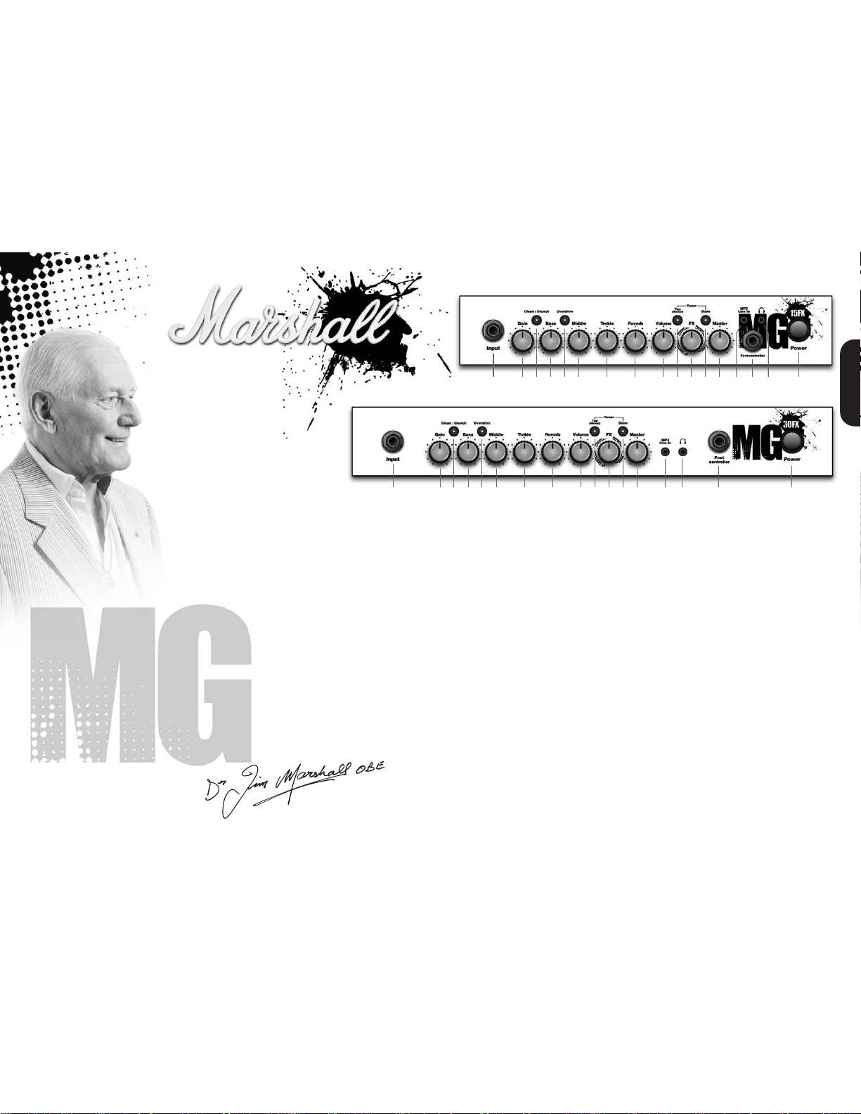
MG15FX
1 2 4 6 7 8 9 11 13 15 173 5 10 12 14 16
1 2 4 6 7 8 9 11 13 14 16 15 173 5 10 12
1. Input JackSocket
Jack input for your guitar. Use a good quality guitar
cable (i.e. one that’s screened/shielded) to help prevent
noise, interference and unwanted feedback.
2. Gain Control
Controls the amount of signal entering the pre-amp and
the amount of distortion createdin the selected channel.
3. Clean : Crunch Switch
Selects between Clean (green) andCrunch (red)channels.
4. Bass Control
Turning up the Bass control will add warmth and lowend depth to your sound.
5. ODSwitch
Selects between OD1 (green) and OD2 (red) channels.
6. MiddleControl
Adjusting the middle frequencies will vary the amount of
body in your sound.
7. Treble Control
Increasing the Treble will make your sounds brighter
and more cutting, turning it down will decrease your
tone’s edge and make it sound softer as a result.
8. Reverb Control
This control lets you add a lush reverb to the selected
channel, from a subtle hint to cavernous and all points
in-between.
9. Volume Control
Controls the volume of the selected channel.
10.Tap (Manual) Switch
Matches the delay FX time to the time between two
pushes. The LED flashes at the selected delay time.
Holding down the Tap switch for longer than 2 seconds
switches theamp between manual and preset mode (pg 2).
When using the optional footcontroller, holding both the
Tap switch and the Store switch will activate the tuner.
11.FX Control
Selects and adjusts one of four effects - Chorus,
Phaser, Flanger & Delay.
12.StoreSwitch
Stores the current amp settings into the current channel
or into the optional footcontroller. When in manual mode
the Store button lights red.
13.Master Control
Controls the master volume of the amplifier.
14.MP3 Line In Socket
Jam to your favourite MP3, CD or tape track by
connecting the line out or headphone output of your
player here. Adjust the volume of your player to match
that of your guitar and you’ve got the perfect ‘playalong’ practice system.
15.FootcontrollerSocket
¼" Jack socket for the connection of the optional
footcontroller (PEDL-90008) - see page 8.
16.Headphones Socket
For use when silent practice is the order of the day.
Connection of headphones will automatically mute the
internal speaker.
17.Power Switch
The power switch turns your amplifier on and off. A
channel switch will light up when your amplifier is turned
on and none will be lit when the amplifier is switched off.
Note: The specific mains input voltage rating that your
amplifier has been built for is shown on the back panel.
Before connecting to the mains electricity supply,
always ensure that your amplifier is compatible with
your electricity supply. If you have any doubt, please get
advice from a qualified technician. Your Marshall dealer
will help you in this respect.
Pleaseensure the amplifieris switchedoff and unplugged
from themains electricity supply before beingmoved.
MG30FX
32
Restoring Settings - WARNING ALL AMP &
FOOTCONTROLLER SETTINGS WILL BE LOST
To restore the unit to factory settings (see handbook
rear cover) you must hold the Store switch (12) while
powering on the unit. The Clean/Crunch (3) and OD (5)
lights will light orange. You can then release the Store
switch (12).
Resetting the amplifier will erase all user Channel
presets and all user Footcontroller settings, replacing
them with the factory presets.
Channel Selection
The amplifier has 4 channels - Clean, Crunch, OD1 &
OD2.
Pressing the Clean/Crunch switch (3) selects between
the Clean (Green Light) and Crunch (Red Light)
channels.
Pressing the OD switch (5) selects between the OD1
(Green Light) and OD2 (Red Light) channels.
When moving from an OD channel to a Clean/Crunch
channel, the unit remembers the last channel you were
in before leaving. E.g. If you have moved from the
Crunch Channel to an OD channel and you press the
Clean/Crunch switch (3), the amplifier will revert back to
the Crunch channel - rather than starting again in the
Clean channel.
Modes
The amplifier operates in two modes - Preset and
Manual.
To change between these two modes, you must hold
the Tap switch (10) down for at least two seconds.
When in manual mode the Store switch (12) lights red
and the selected channel light (3 or 5) will start to flash.
The amplifier will remember the last mode it was in after
power off and revert to it the next time it is powered on.
Preset
This is the factory default operation of the amplifier.
In Preset mode the position of all controls except
Master Volume (13) are stored within each channel.
Each channel should be considered a preset.
Selecting a channel automatically recalls the settings
stored within the channel. Note: The physical position of
the front panel controls, except Master Volume (13)
which is not storable, will now not match the actual
settings of the amplifier. All front panel switches will
automatically update.
Altering a control will cause the associated parameter to
jump to the current physical position of that control.
When a control is altered the selected channel light (3
or 5) will start to flash indicating that the current preset
has been altered.
To store the updated settings, push the Store switch
(12).
If you select another channel without pressing Store
(12) then any altered settings will be lost as the new
channel and its settings are recalled.
Manual
In manual mode the amp’s settings always match the
physical positions of the controls.
Changing channel only changes the channel, NO
presets are recalled, NO other controls are altered.
Pressing Store (12) will store the current settings into
the selected channel. These can then be recalled when
using the unit in Preset mode.
When channel settings have been stored the current
channel light (3 or 5) will stop flashing indicating the
preset has been saved.
Reverb & FX
The amplifier provides two simultaneous effects,
Reverb and one of four FXs (Chorus, Phaser, Flanger
or Delay)
Reverb
The Reverb control (8) sets the amount of signal sent to
the reverb section - allowing the reverb to spill between
channels as different presets are recalled. When the
Reverb control (8) is set to ‘0’ the reverb is switched off,
the status of the reverb is also indicated on the optional
footcontroller.
FX
The FX control is split into four segments and selects
the type of FX and adjusts its associated settings.
When the FX control is set to ‘0’ the FX are switched
off, the status of the FX is also indicated on the optional
footcontroller.
Tap Tempo
The Tap Tempo switch (10) is used for the Delay effect
only.
The Tap Tempo switch matches the delay time to the
time between two presses.
The Tap Tempo LED flashes red at the
selected/recalled delay time.
The number of repeats is reduced as the delay time
decreases.
If you change from a channel with delay to one without
delay the effect will spill between channels.
If you change from a channel with delay to a channel
with delay set to a different delay time the delay effect
will not spill between channels.
MP3/Line In
The 3.5mm MP3 / Line In socket (14) allows the
connection of an external audio source e.g. MP3 or CD
player.
Headphones
The 3.5mm Headphones socket (16) allows the
connection of a pair of headphones. When a jack is
inserted into the headphones socket the unit’s speaker
is muted.
Power
The Power switch (17) turns the amplifier on and off. If
current settings have not been stored they will be lost.
MG15FX & MG30FX Overview
0
Chorus
Phaser
Flanger
Delay
FX Off
Speed increases and depth is reduced as
knob is turned clockwise.
Speed increases as knob is turned
clockwise.
Speed increases, feedback and depth are
reduced as knob is turned clockwise.
Delay level is increased as knob turned
clockwise.
Power (RMS) 15W
Channels 4
Speaker 1x8"
Weight (kg) 7.7kg
Size (mm) W, H, D 382 x379 x205
MG15FX Technical Specification
Power (RMS) 30W
Channels 4
Speaker 1x10"
Weight (kg) 10.8kg
Size (mm) W, H, D 480 x420 x225
MG30FX Technical Specification
ENGLISH
* EUROPE ONLY - Note:
This equipment has been tested and found to comply with the requirements of the EMC Directive
(Environments E1, E2 and E3 EN 55103-1/2) and the Low Voltage Directive in the E.U.
* EUROPE ONLY - Note:
The Peak Inrush current for the MG15FX is 2.5 amps.
The Peak Inrush current for the MG30FX is 5 amps.
Note:
This equipment has been tested and found to comply with the limits for a Class B digital device, pursuant to part 15 of the FCC rules.
These limits are designed to provide reasonable protection against harmful interference in a residential installation. This equipment generates,
uses and can radiate radio frequency energy and, if not installed and used in accordance with the instructions, may cause harmful interference
to radio communications. However, there is no guarantee that interference will not occur in a particular installation. If this equipment does cause
harmful interference to radio or television reception, which can be determined by turning the equipment off and on, the user is encouraged to try
to correct the interference by one or more of the following measures:
*
Reorient or relocate the receiving antenna.
*
Increase the separation between the equipment and the receiver.
*
Connect the equipment into an outlet on a circuit different from that to which the receiver is connected.
*
Consult the dealer or an experienced radio/TV technician for help.
Follow all instructions and heed all warnings
KEEP THESE INSTRUCTIONS !
 Loading...