

Page 1
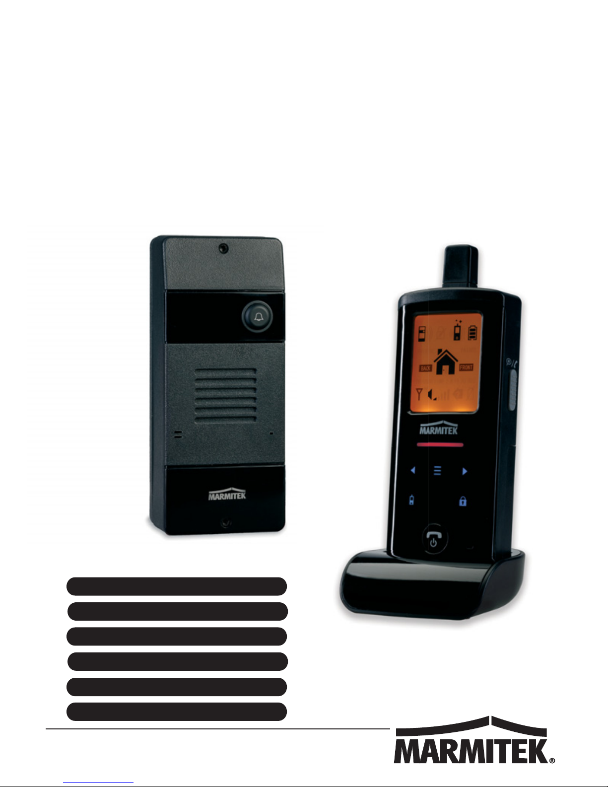
DOOR
20651/20151116 • DOORPHONE 170™
ALL RIGHTS RESERVED MARMITEK ©
DOORPHONE 170
™
USER MANUAL 3
GEBRAUCHSANLEITUNG 23
GUIDE UTILISATEUR 45
MODO DE EMPLEO 67
MANUALE D’ISTRUZIONI 89
GEBRUIKSAANWIJZING 111
Page 2

© MARMITEK
2
Page 3

DoorPhone 170
3
ENGLISH
TABLE OF CONTENTS
TABLE OF CONTENTS ............................................................................ 3
INTRODUCTION ....................................................................................... 3
SAFETY WARNINGS ............................................................................... 4
FEATURES ............................................................................................... 4
STANDARD ACCESSORIES .................................................................... 5
GETTING STARTED ................................................................................ 6
POWER SUPPLY .................................................................................. 6
DOOR UNIT ....................................................................................... 6
HANDSET .......................................................................................... 7
PAIRING THE HANDSET AND DOOR UNIT ........................................ 8
MOUNTING OF DOOR UNIT .................................................................. 10
Always close .................................................................................... 11
Always open ..................................................................................... 11
Auxiliary terminal .............................................................................. 11
CONTROLS LAYOUT ............................................................................. 12
LCD ......................................................................................................... 13
OPERATION ........................................................................................... 16
GATE VOLUME ................................................................................... 16
ALARM MODE .................................................................................... 16
TRIGGER TIME ................................................................................... 16
DOOR LOCK OPEN ............................................................................ 17
INTERCOM ............................................................................................. 20
PRECAUTION ......................................................................................... 20
TROUBLE SHOOTING GUIDE ............................................................... 21
TECHNICAL DATA ................................................................................. 22
INTRODUCTION
Thank you for purchasing this Digital Wireless Doorphone System. Your
system has been manufactured and checked under the strictest possible
quality control to ensure that each system leaves the factory in perfect
condition. In the unlikely event you find any defect or experience any
problem, please contact our service centre or dealer, do not attempt to
repair by yourself.
Please read this manual carefully to obtain optimum performance and
extended service life from the system.
Page 4

© MARMITEK
4
SAFETY WARNINGS
x Do not expose the components of your system to extremely high
temperatures or bright light sources.
x In case of improper usage or if you have altered and repaired the
product yourself, all guarantees expire. Marmitek does not accept
responsibility in the case of improper usage of the product or when
the product is used for purposes other than specified. Marmitek does
not accept responsibility for additional damage other than that
covered by the legal product responsibility.
x This product is not a toy. Keep out of reach of children.
x Do not open the product (battery panel excepted): the device may
contain live parts. The product should only be repaired or serviced by
a qualified expert.
x Keep batteries out of the reach of children. Dispose of batteries as
chemical waste. Never use old and new batteries or different types of
batteries together. Remove the batteries when you are not using the
system for a longer period of time. Check the polarity (+/-) of the
batteries when inserting them in the product. Wrong positioning can
cause an explosion.
x Only connect the adapter to the mains after checking whether the
mains voltage is the same as the values on the identification tags.
Never connect an adapter or power cord when it is damaged. In that
case, contact your supplier.
FEATURES
x Digital transmission ensures interference-free conversation
x Two way communication
x Long operating range of 300m in open space
x Selectable audio, visual or vibration alert for doorbell
x Remote control of electric door lock
x The door unit is provided with an extra AUX
connector which
gets activated when the doorbell button is pressed. Among other
functions, this can be used for the activation of an (existing)
conventional doorbell or for switching on the lights in the
door/entrance.
x Audible and visual alert for out-of-range and low battery level
x Intercom function between handsets
x Door unit complies to IP54 standard
x Extremely easy installation without any wiring needed
Page 5

DoorPhone 170
5
ENGLISH
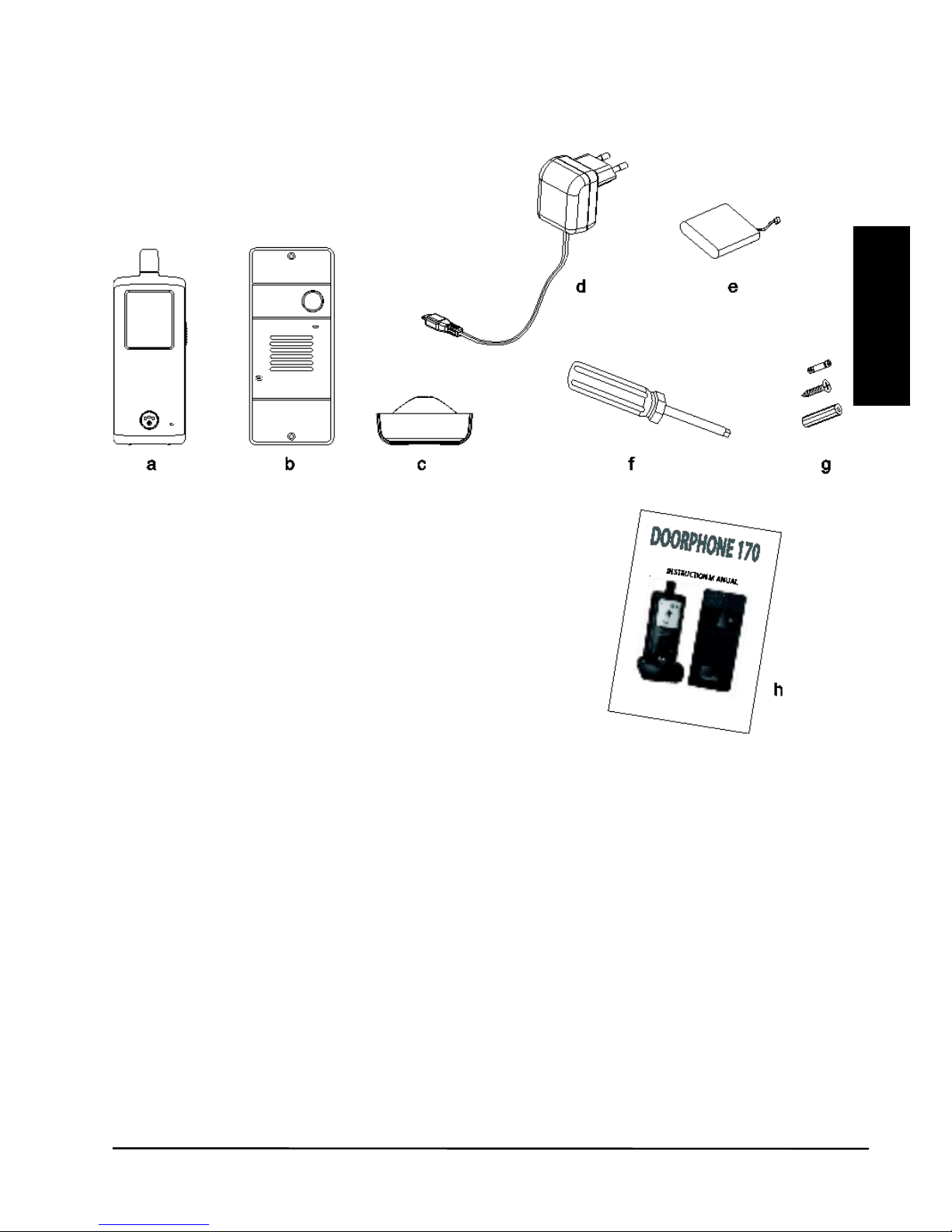
STANDARD ACCESSORIES
a. Handset
b. Door unit
c. Charger stand
d. Switching power supply
e. Rechargeable Li battery pack (installed in handset)
f. Tool
g. Screws and rivets
h. Instruction manual
Page 6
© MARMITEK
6
GETTING STARTED
POWER SUPPLY
DOOR UNIT
The door unit can be
powered in two ways.
1. Using batteries.
(power failure)
2. Using external
power adapter.
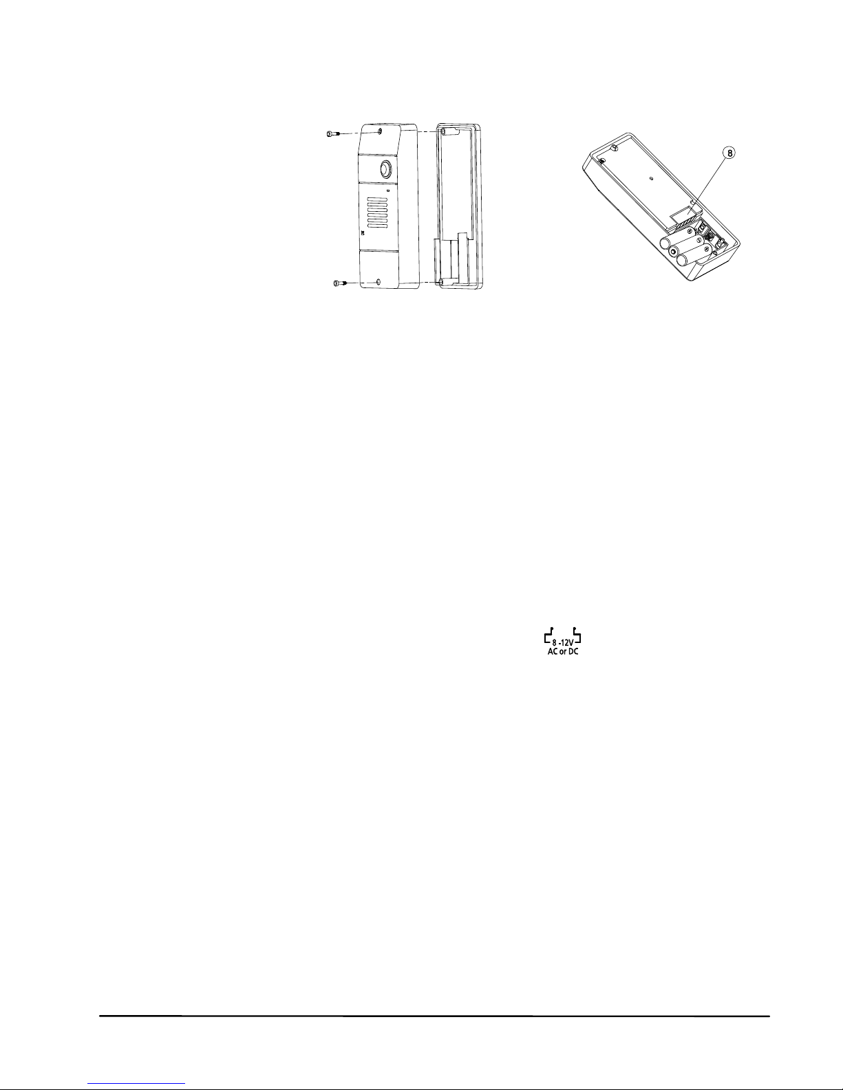
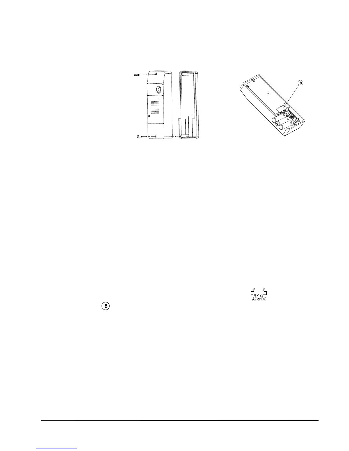
1. With the supplied tool, loosen the screws holding the unit from the
mounting bracket. The screws are made specifically for anti-theft
purposes, it is necessary to keep the tool in a safe place for when
you need it later when replacing the batteries. Insert three UM-4 size
AAA alkaline cells into the battery compartment, observing correct
polarity. We strongly recommend using alkaline batteries instead of
rechargeable batteries because at low temperatures (below 0˚C),
rechargeable ones have poor performance and their capacity will fall.
Please note the alkaline batteries are used only as a backup in case
of mains failure. They can only last for 1 - 2 days under normal
operation.
2. The door unit is powered with 12V DC, or 8 to 12V AC, which is
often available at the entrance (bell transformer). Connect the power
supply to the terminals (8) at the back marked
In case of a power failure, the unit will automatically switch to power
from alkaline batteries (if installed).
You can use your existing doorbell transformer as power supply, as
long as it can provide 8…12V, AC or 12V DC. When you want to use
another 12V power supply, make sure it has a stable voltage output
(Switching adapter 100-240VAC (V) 12VDC) and not a transformer
type that has a high no load voltage!
Page 7
DoorPhone 170
7
ENGLISH
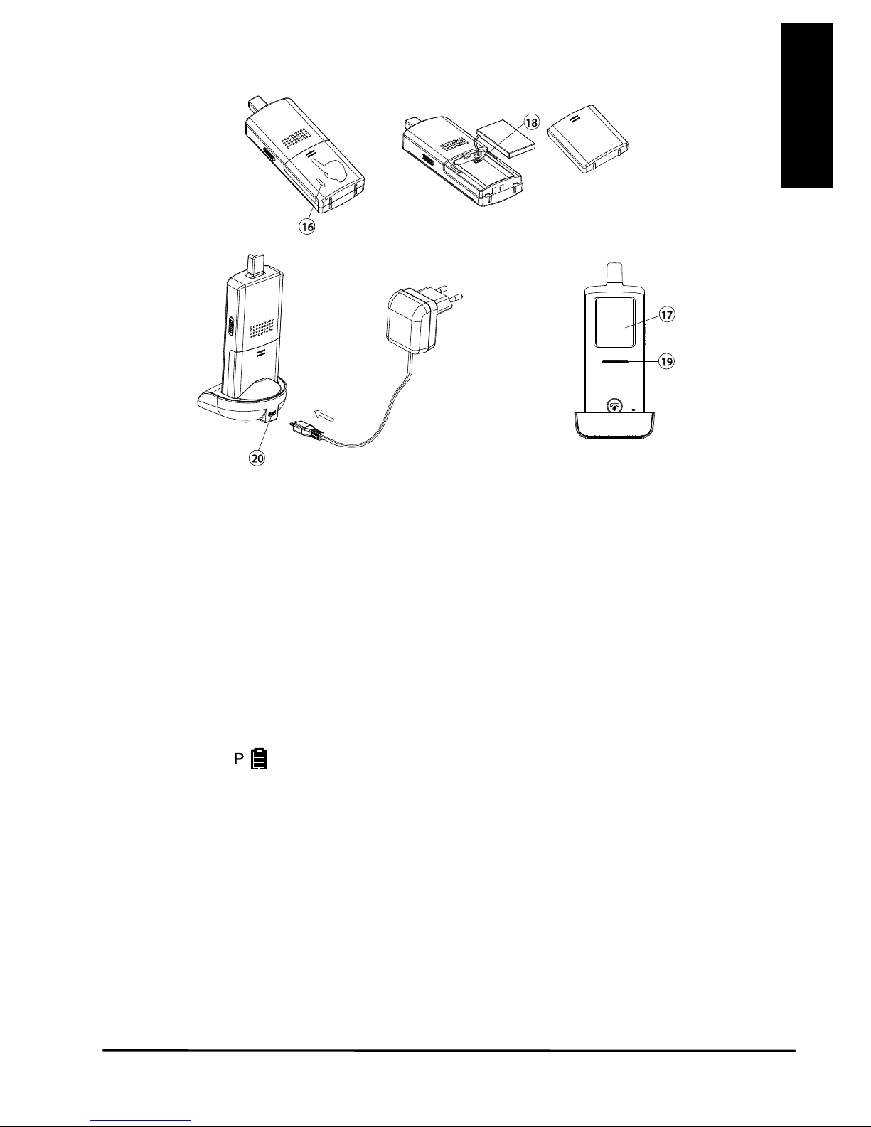
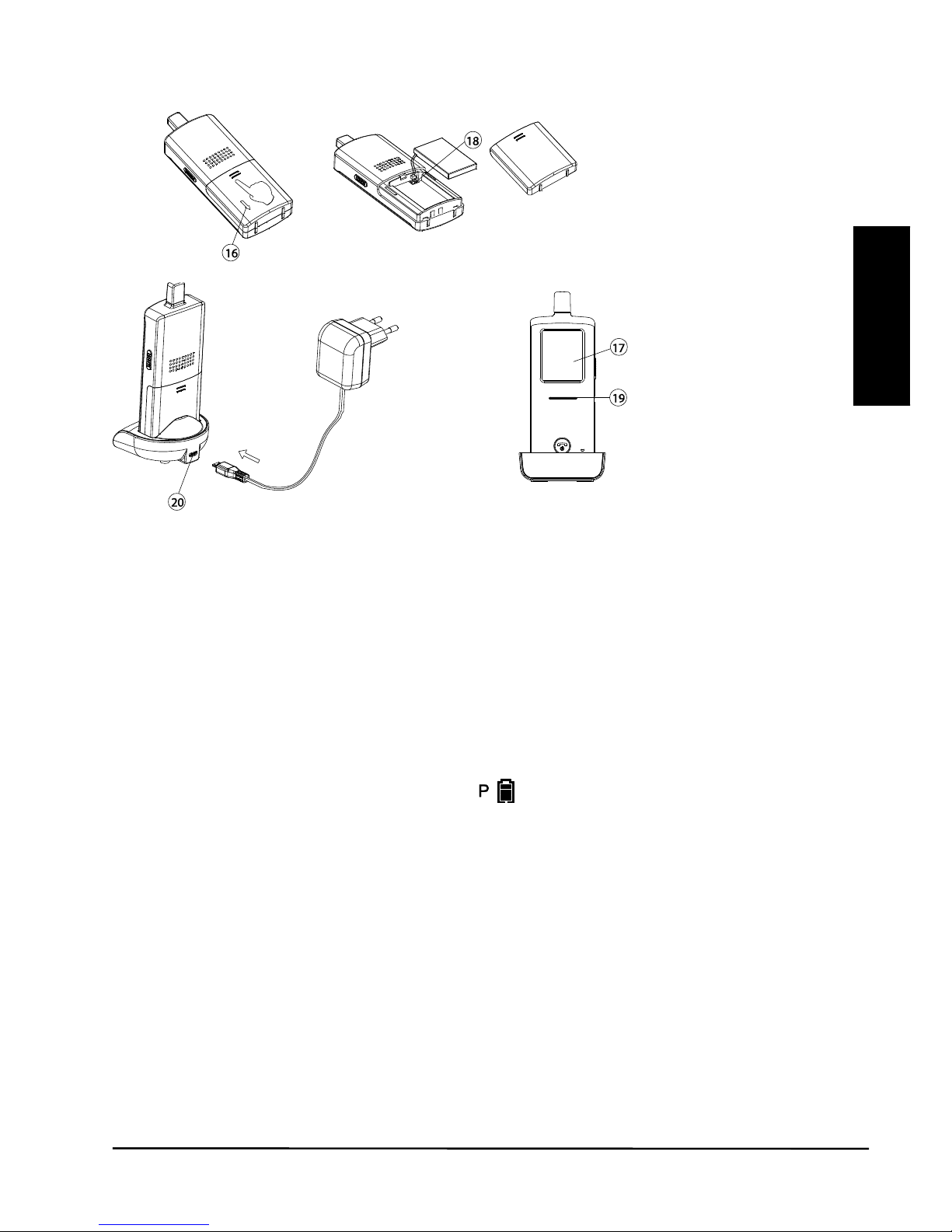
HANDSET
1. The supplied Li polymer battery pack is already installed in the
handset. (To replace, press down the lock button (16) and slide open
the battery door, take out the battery pack and disconnect from the
socket (18).)
2. With the handset remaining switched off, place it onto the charger
stand.
3. Plug in the supplied AC power supply into an AC outlet and connect
its output plug to the USB port (20) located at the back of the charger
stand.
4. The charging indicator (19) should light up red during the charging
process. Adjust the position of the handset in the charger stand in
case this indicator does not light up. During charging, the battery
level icon
will show up in LCD and the segments inside the icon
will flash in turn.
5. The battery pack should be fully charged within 4 hours when used
for the first time. The power indicator (19) will now go off (if the
handset is switched off) or turn steady blue (if the handset is
switched on)..
6. Now the unit can be switched on and ready for operation. Taking out
the unit or keeping it placed in the charger stand will cause no
damage to the battery. In the latter case, when the battery is being
consumed and the voltage falls to a certain level, the charger stand
will automatically charge up the battery.
TO AC OUTLET
Page 8
© MARMITEK
8
CAUTION: BE SURE THE BATTERY IN THE HANDSET IS A
RECHARGEABLE TYPE BEFORE YOU PLACE IT IN THE CHARGER
STAND, OTHERWISE AN EXPLOSION MAY RESULT.
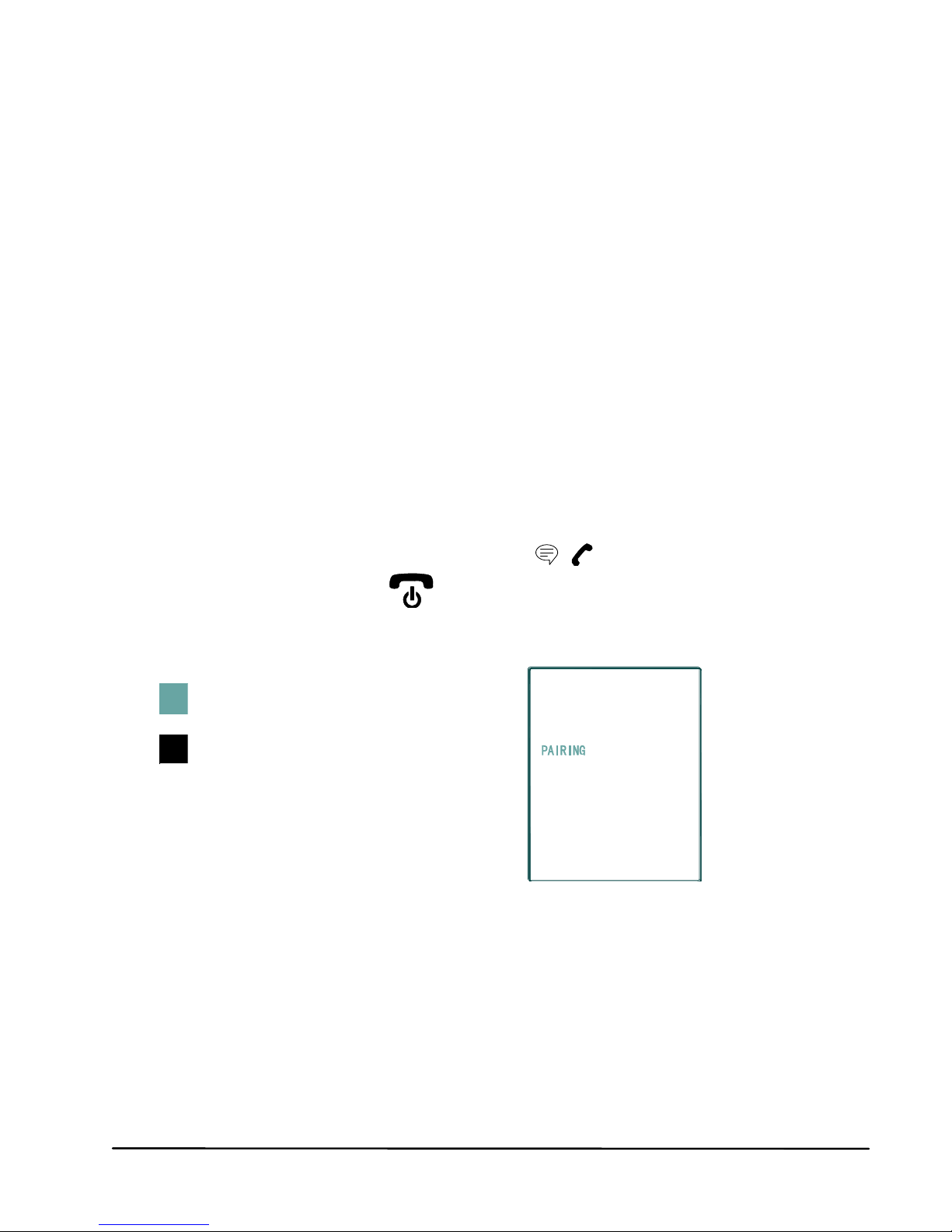
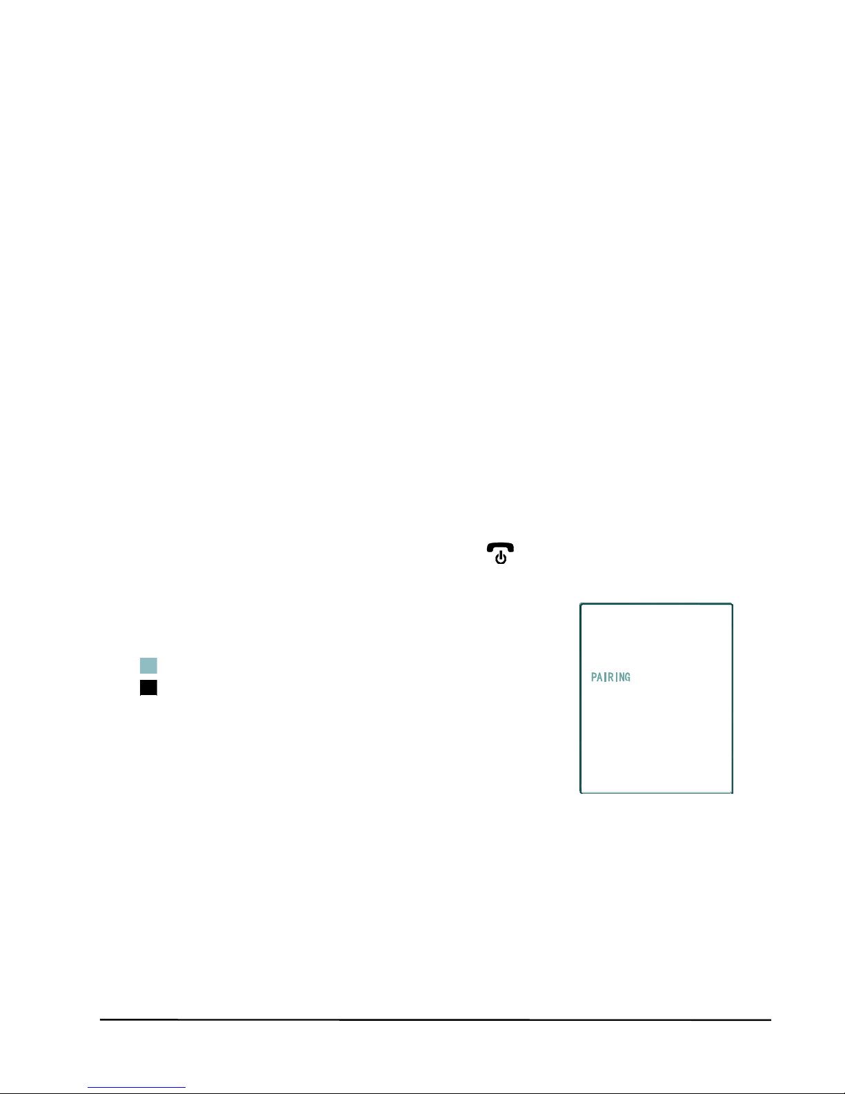
PAIRING THE HANDSET AND DOOR UNIT
This process is to match the door unit with the handset so that they can
communicate with each other and so that no other devices (even a door
phone of an identical model) can interfere with you or the receiving of
your signal.
The door unit and handset are already paired with a factory pre-set code
when they are shipped from the factory. However, we recommend pairing
them again to achieve better privacy and to avoid a false triggering of a
door lock from a nearby door phone system.
To perform the pairing process, it is necessary to use alkaline batteries as
the power supply in the door unit, while the12V DC supply should be
disconnected temporarily.
1. Place the door unit and handset close to each other within a distance
of 1m.
2. Press and hold the talk/answer button
(16), then long press the
power ON/OFF button
(15) to switch on the unit. The screen
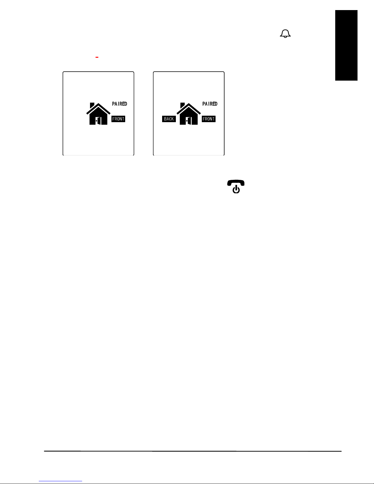
(17) will show the following:
Flashing
Light up steady
3. Press and hold the pairing button (7) at the back of the door unit
while installing the alkaline batteries. The call indicator (4) will start
flashing after 3 sec, showing that the door unit has entered pairing
mode.
Perform the same for the door unit that is intended to be used at the
back gate (option, not included).
Page 9
DoorPhone 170
9
ENGLISH
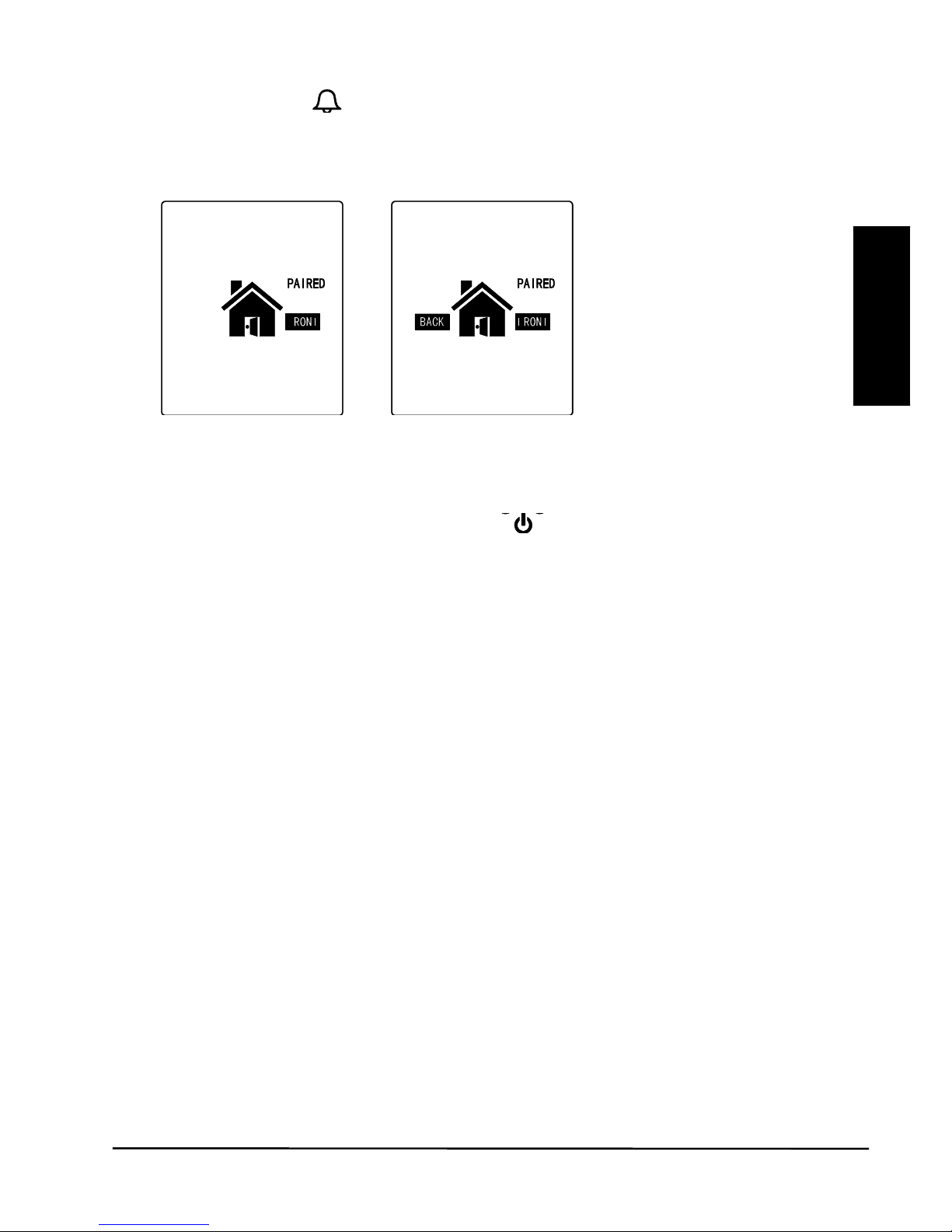
4. Now release the pairing button (7) , press call button (1) on the
front gate door unit (DO NOT press the call button on the back gate
door unit.). Two “Di Di” sounds will be heard. The screen (17) will
show the following once pairing is successful:
(in case there is a
back gate door unit)
The call indicator (4) on both front gate & back gate door units should
stop flashing and remain steady on.
5. Long press the Power ON/OFF button (15)
to switch off the
handset. Take out the alkaline batteries from the door unit and then
re-install again or connect to the power supply.
6. The doorphone is now ready for operation.
If the pairing process is not successful (the “PAIRING” continues to flash
in the LCD of the handset), repeat the procedures from step 1 again.
N.B. In case you are having two or more handsets as well as a back gate
door unit, always perform the pairing process with all door units and
handsets together and with the handsets being set in pairing mode first.
Remember every time you add on new units to the system, either handset
or door unit (for back gate use), it is necessary to perform the pairing
process all over again with all the units together or otherwise the new
units will not work with your original DoorPhone 170.
Page 10
© MARMITEK
10
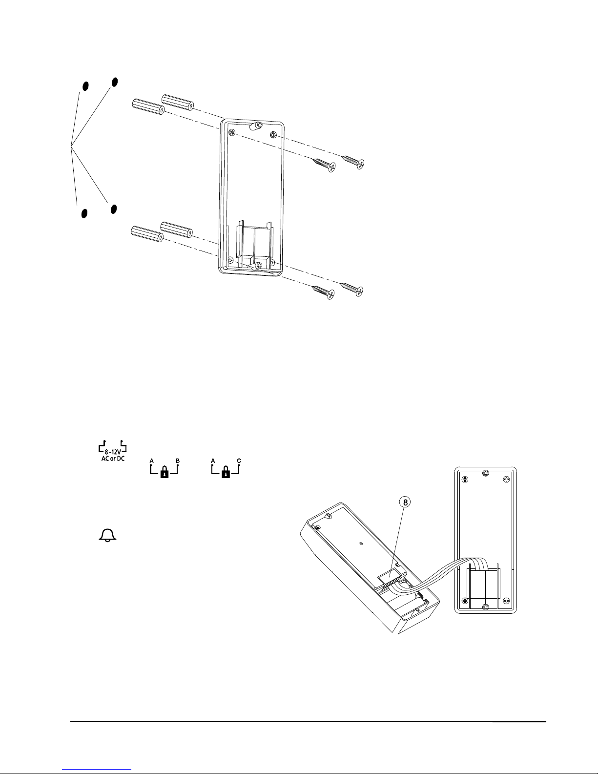
MOUNTING OF DOOR UNIT
1. Select a location near your door entrance where the surface is not
too rough. We recommend that you do some polishing to get a plane
surface or otherwise the unit may not be able to mount properly.
It should be noted that the mounting bracket should not be installed
on metal screening surfaces or in the vicinity of other electronic
devices that may reduce the operating range. Using the supplied selftap screws, fix the mounting bracket onto the wall.
2. In case there is a 12V DC supply, connect to the terminals marked
at the back of the door unit. In addition, there are also terminals
marked
and for connecting to an electric
door latch which can be remotely opened by
the handset. Where a DC supply
is available, the call button (1)
will be automatically
illuminated once the
environment gets dark. This
feature and the electric door latch
opening feature will not operate when
using alkaline batteries so as to keep a
long battery life.
CAUTION: When using a DC supply, in case the electric door latch does
not function, reverse the polarity it is connected to and try again.
The two most common types of electric door latches on the market are
either “always close” or “always open”.
Drilled holes
INSERT PLUGS INTO HOLES
(FOR CONCRETE WALL
ONLY)
Page 11

DoorPhone 170
11
ENGLISH
Always close
These two terminals normally provide a 12V supply. During
communication, once the door lock opening button
is pressed, this
voltage will drop to 0V temporarily for duration of time as specified by the
TRIGGER TIME function.
Always open
These two terminals normally provide 0V. During communication,
once the door lock opening button (13)
is pressed, the terminals will
provide a 12V supply temporarily for duration of time as specified by the
TRIGGER TIME function.
Under no circumstances should AC mains Voltage be directly connected
to the terminal blocks (8)!
Auxiliary terminal
These two terminals act like a switch and will be short circuited as
long as the doorbell button
(1) is pressed, however, there is no voltage
supply from these terminals. They can be used to trigger a conventional
door chime or a courtesy light at the entrance.
3. Now insert the 3 pcs AAA (UM-4) alkaline batteries into the battery
compartment as this can serve as a battery back-up in case the 8 12V power supply fails.
4. Install the back of the door unit onto the mounting bracket using the
supplied tool.
5. The door unit is housed in a high impact ABS/PC cabinet which can
achieve the professional grade ruggedness required in most outdoor
applications. Rubber gaskets seal around all of the joints to keep out
dust, rain and snow, assuring years of reliable operation even in
harsh environments. The unit meets IP-54 standard and can operate
from -20˚C to 50˚C.
TO DC SUPPLY
AND ELECTRIC
DOOR LOCK
Page 12
© MARMITEK
12
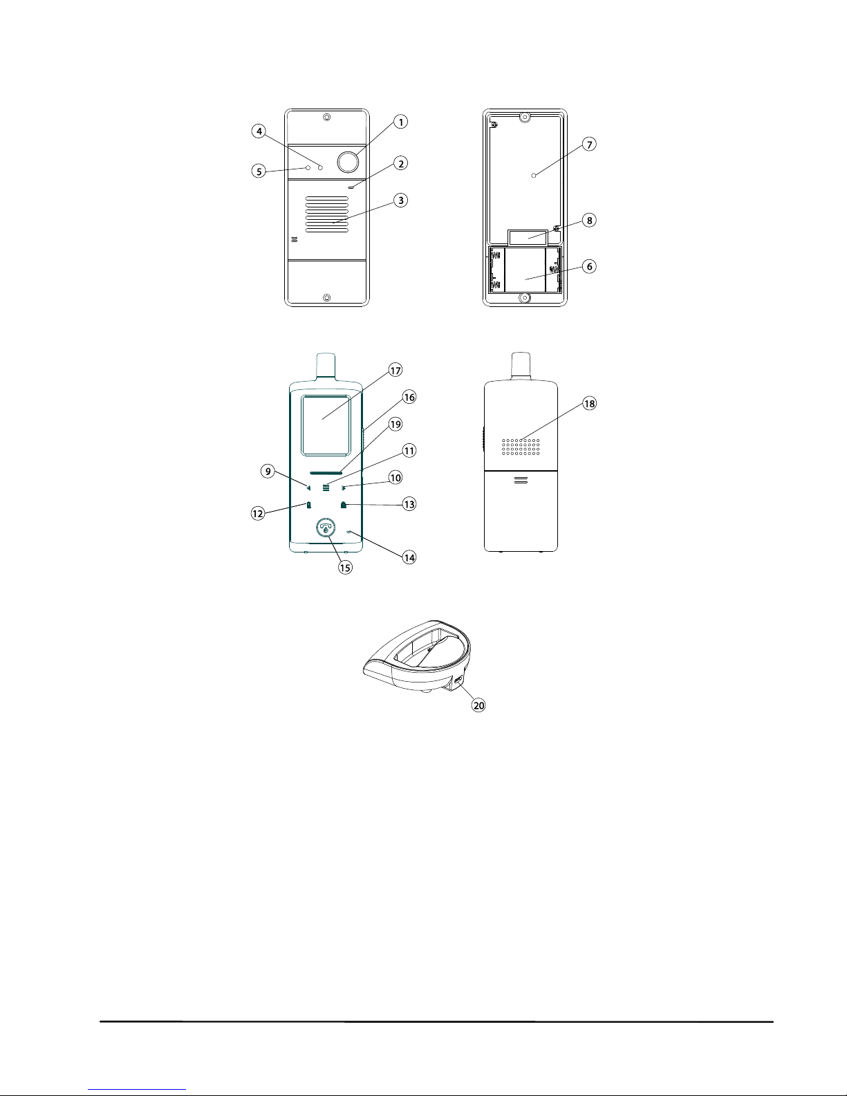
CONTROLS LAYOUT
Door unit
Handset
Charging Stand
1. Call button
2. Microphone
3. Speaker
4. Call indicator
5. Light sensor
6. Alkaline battery
compartment
7. Pairing button
8. Terminal block
9. Volume down key
10. Volume up key
11. Menu key
12. Handset Call key
13. Door lock open button
14. Microphone
15. Hang up and power
ON/OFF button
16. Talk and answer button
17. LCD
18. Speaker
19. Power and battery low
indicator
20. USB port
Page 13
DoorPhone 170
13
ENGLISH
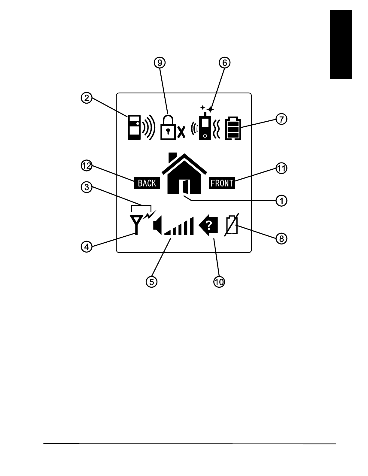
LCD
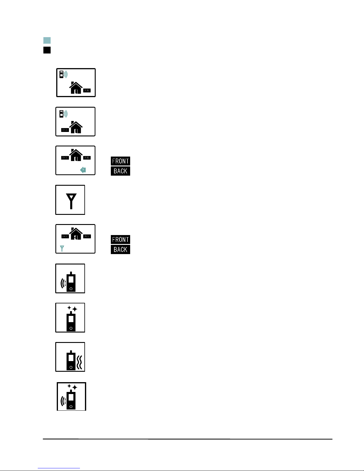
1. Door lock opened
2. Doorbell ringing
3. Transmit icon
4. Reception mode Out of range icon
5. Speaker volume bar graph
6. Door chime, flashing light and vibrating alert selected
7. Battery Level indicator
8. Door unit battery low
9. Door lock de-activated
10. Missed call
11. Front gate
12. Back gate
Page 14
© MARMITEK
14
Flashing
Steady light up
A. Front gate doorbell ringing
B. Back gate doorbell ringing
Missed call,
C. (Front gate)
(Back gate)
D. Reception mode
Out of range alert
E. (Front gate)
(Back gate)
F. Door chime alert selected
G. Flashing light alert selected
H. Vibrating alert selected
I. Door chime and
flashing light alert selected
Page 15
DoorPhone 170
15
ENGLISH
J. Door chime and
vibrating alert selected
K. Flashing light and
vibrating alert selected
L. Door chime, flashing light and
vibrating alert selected
M. Door lock opened
Door unit battery low
N. (Front gate)
(Back gate)
O. Handset battery low
P. Handset Battery level
Q. Speaker volume
R. Door lock de-activated
Page 16
© MARMITEK
16
OPERATION
1. Switch on the handset with a long press (over 3 seconds) of the
Power ON/OFF button (15)
. Press the same button again in
case you want to switch off the unit.
2. The power indicator (19) will light up blue. In case the Li battery has
run down, the power indicator will start flashing blue. At the same
time, the battery icon
shown on the LCD (17) will become empty
and flashing. Place the unit into the charger stand to charge up the
battery. During charging, the segments inside the battery level icon P
will flash in turn irrespective if the unit is switched on or off. To
protect the battery, if the unit is not being re-charged when the icon O
shows up, it will be switched off automatically after 10 minutes.
3. During standby mode, short press of the Talk/answer button /
(16) will initiate the backlight and activated the touch keys
Long touch the menu key (11) for over 3 sec to enter programming
mode & LCD show following:
GATE VOLUME
This will set the speaker volume of the door unit. Use
the left/right key
(9) (10) to select between the 4
levels with 1 being the lowest and 4 being the highest
volume. Short touch the menu key (11) to confirm
your setting.
ALARM MODE
This will set the method of alert when a visitor calls,
either with a ding-dong sound or vibration or both. Use
the left/right key
(9) (10) to select between
(ding-dong sound and vibration) or (ding-dong
sound only) or
(vibration only). Short touch the menu
key
(11) to confirm.
The corresponding icon will be shown on the top of the LCD (18).
TRIGGER TIME
This is the duration time for how long the door lock is being
triggered. Use the left/right key
(9) (10) to select
between 2, 8, 15, or 30 seconds. Short touch the menu
key (11) to confirm.
Page 17
DoorPhone 170
17
ENGLISH
DOOR LOCK OPEN
This is to activate or deactivate the door lock open
key
(13). Use the left/right key (9) (10) to select
between “ACTIVATE” or “DEACTIVATE”, Short touch
the menu key (11) to confirm. In case
DEACTIVATE is selected, the icon
will show up at
the top part of the LCD (17).
To return to standby mode, short press the power/hang up button
(15). Alternatively, if no key is being touched for over 1 min, the
handset will return to standby mode automatically.
4. During conversation, the sound volume heard through the speaker
(18) can also be adjusted using buttons
9 & 10 and the speaker
volume bar graph will change correspondingly. Please note the
loudness of door chime is fixed and cannot be adjusted.
5. Make sure there is a power supply to the door unit (either by 12V DC
or alkaline batteries). Now press the Call button (1)
, a ding-dong
tone will be heard and the Call indicator (4) will start to flash. Until a
handset answers the call, the ding-dong tone will be heard
periodically, reminding the visitor to keep waiting. In case there is no
answer after 20 seconds, the door unit will end the call by itself and
the Call indicator (4) will go off. Press the Call button (1)
to
initiate the call again.
N.B. In case there are two door units (front gate and back gate), only
the unit whose call button (1)
is pressed first will send out a call
signal to the handset, the remaining unit will remain in standby mode
until the conversation is over. If its call button (1)
is pressed
during this period, a “Be-Be” sound will be heard and the call
indicator (4) will flash two times, indicating the unit is in standby
mode.
6. Once the call is answered, the Call indicator (4) will light up steady
and the ding-dong tone will stop ringing. Conversation can now be
conducted by speaking into the Microphone (2)
7. Upon receiving a call, either icon A
or icon B will appear on
the screen, depending if the call is from the front gate or back gate (in
case you have purchased an optional door unit for back gate). The
handset can answer the call by pressing the Answer button (16)
and the reception mode icon D
will show up in LCD.
Now conversation is possible and the voice of the visitor can be
heard from the speaker (18). To talk back to the visitor, press and
hold the PTT button (16)
and speak towards the Microphone
(14), the transmit mode
shows up. Release the PTT button
Page 18

© MARMITEK
18
(16) after finish speaking to listen to the visitor, the reception
mode icon D
will show up again. It should be noted that the voice
of the visitor will not be heard while pressing the PTT button (16)
.
Upon finishing the conversation, press the Hang up button (15)
to
end the call.
The DoorPhone 170 has an automatic end call feature. In case the
resident does not talk back to the visitor (i.e. press the PTT button
(16)
for more than 90 sec, the call will be ended automatically.
This feature is useful for protecting your privacy in case you forget to
end the call by pressing the Hang up button (15)
.
8. Once a call has been answered, you can use the door lock open
button (13) to remotely open the electric door latch for the visitor
(this function is only available if there is a 12V DC supply to the door
unit and your door is equipped with an electric latch). Touch and hold
the button (13)
for over 2 seconds, wait a while and the icon M
will appear on the screen, showing that the door latch is open. The
icon M
will disappear after a duration as specified by the trigger
time function.
Under standby mode (i.e. when no call is set up between the handset
and door unit), the electric door latch of the front door can also be
opened by a long press of button (13) for over 2 sec. The Call
indicator (4) on the door unit also lights up for a duration as specified
by the trigger time function.
To avoid misuse by children, this door lock opening function can be
activated or deactivated. When deactivated, as indicated by the
on
the LCD (17), pressing the button (13)
will have no effect.
9. For systems equipped with several handsets, all the handsets will be
alerted of an incoming call. However, only the handset which first
presses the Answer button (16) can set up conversation with
the door unit. The remaining handsets will return to standby mode
and their buttons will become de-activated until the conversation
ends, making it impossible for them to interfere with the conversation.
10. Under the circumstances of an unanswered call from a visitor (e.g.
you are away from home or located at a place which is out of range
from the door unit), the icon C
will appear on the screen. This
icon is useful to remind you that somebody has called. Press any
button momentarily to remove this icon.
11. Whenever the handset is located at a spot which is outside of the
communication range of the door unit (either front or back gate), an
alarm will be heard and the icon E
will appear on the screen.
Such an alarm is not immediate and it will alert you only when you
are out of range for over 2 minutes (when the 12V DC supply is
Page 19
DoorPhone 170
19
ENGLISH
available or 20 minutes if the battery is used). Pressing the
talk/answer button (16)
or the hang up button (15)
momentarily can stop the alarm but the icon E
will still remain.
Once the handset falls back in range, the alarm will stop and the icon
E will disappear.
N.B. This out of range alert will also occur in case the batteries of the
door unit run down and its DC power is cut off.
12. Under normal operation, the back-up alkaline batteries inside the
door unit (we suggest using good quality batteries such as Duracell)
can last for 2-3 days.When there is no 12V DC supply and the
backup batteries become run down, the icon N
will appears on
the screen and an alarm will be heard, reminding you to replace it
with new batteries in the respective door unit. Pressing the
talk/answer button (16)
or the hang up button (15)
momentarily can stop the alarm but the icon N
will still remain
until new batteries are installed.
N.B. In case the handset is out of range and the door unit battery
goes low at the same time, then only the out of range icon E
is
shown and its alarm will be heard.
13. Whenever the buttons (except the PTT button (16) ) or hang up
button (15)
on the handset are pressed, a tone will be heard to
validate your entry.
14. Once the Light sensor (5) detects a low light intensity, the Call button
(1)
on the door unit will become automatically backlighted (only if
a12V DC supply is available).
Page 20

© MARMITEK
20
INTERCOM
This function is applicable only if you have two or more handsets. Please
note all units must be paired together.
a. Under standby mode, touch and hold the handset call key (12) , a
“do – do” sound will be heard.
b. The called handset will show the selected incoming call alert. Press
the Answer button (16)
to answer the call. The “do-do” sound
on the calling handset will stop.
c. Now both handsets can converse with each other using the Answer
button (16)
.
d. Either party can press the Hang up button (15)
to end the
conversation.
e. The call will also be ended automatically if the PTT button (16)
on either party is not pressed for over 60 sec.
For systems with more than two handsets, the incoming call alert on the
remaining handsets will stop once the call is answered. In case nobody
answers the call, the alert will stop 20 seconds later.
N.B. Selective calling of a particular handset is not possible. Whenever a
handset initiates a call, all of the remaining units will be alerted and can
answer the call. However, only the unit which first presses the Answer
button (16)
can reply to the call, all others will be excluded from the
intercom.
CAUTION: The two handsets under intercom may not be able to detect a
call from the door unit. So it is advisable to keep the intercom
conversation short.
PRECAUTION
x Use only the supplied AC switching power supply. Use of another
supply may cause damage to the handset.
x Do not mix old and new alkaline batteries in the door unit.
x When not using the door phone for a long period of time, remove all
batteries from the handset and door unit to avoid battery leakage.
x Do not leave the handset exposed to strong sunlight for a long period
of time or near any heat source, moisture and excessively dusty
environments.
x Do not open the cabinet, no serviceable parts are inside.
x When using for the first time, switch off the handset and charge up
the supplied battery pack for 4 – 5 hours, using the charger stand.
Page 21
DoorPhone 170
21
ENGLISH
TROUBLE SHOOTING GUIDE
Problem
Possible Causes
Solution
Handset and door unit
cannot communicate
Handset and door unit
has different ID codes
Battery has run down
Perform pairing
process
Replace new battery
in
door unit
Recharge battery in
Handset using
charger stand.
Communication
distance become
s
short
er
Many steel structures
between Handset and
door
unit
Battery has run down
Relocate the position
of Handset
Replace new battery
in
door unit
Recharge battery in
Handset using
charger stand.
Out-of-range alert
always on
No power supply to
door
unit
Replace new battery
or check DC supply to
door unit.
Self battery low icon
always on
Battery pack is
damaged and cannot
be recharged.
Replace new battery
pack
.
Door latch cannot be
remotely opened by
handset
Door lock opening
button
(13) is
deactivated
No DC supply to door
unit
Wrong connection at
terminal block
Activate door lock
opening button (13)
Check if DC supply is
available
Make proper
connection
Cannot perform
intercom between
Handsets
The unit is not
properly paired
Battery has run down
Perform pairing
process
Recharge battery
using charger stand
New door unit (back
gate
) cannot
communicate with
indoor unit
The new unit is not
properly paired to
existing units
Perform pairing
process
Page 22

© MARMITEK
22
TECHNICAL DATA
Handset
Power: Rechargeable Li battery pack
800mAh 3.7V
Charger: 6V 600mA
Power consumption: Stand-by 36mA
Active Transmission mode 130mA
Reception mode 270mA
Doorbell Selectable audio, visual or vibration alert
Dimensions: 50x142x22mm
Door unit
Range Up to 300m in free field, up to 50m through
walls and ceilings.
Backup Power Battery (3x AAA alkaline, for 3 days backup,
not included)
Power adapter 8 - 12 VAC or 12 VDC, 1000mA (not supplied)
Frequency 863-870Mhz
Power consumption Stand-by 54mA
Active Transmission mode 120mA
Reception mode 260mA
Material ABS / PC / PMMA
Connection External power 8-12V AC or 12V DC MAX 1A
Make connection 8-12V MAX 1A
Break connection 8-12V MAX 1A
AUX connector MAX 12V/200mA
Ambient temperature: - 20° C to + 50° C
IP value IP54
Dimensions 57x139x30mm
In order to continue improving the product, Marmitek reserves the right to change
specifications and/or designs without prior notice.
Page 23

DoorPhone 170
23
DEUTSCH
INHALTSVERZEICHNIS
INHALTSVERZEICHNIS ......................................................................... 23
EINFÜHRUNG ........................................................................................ 23
SICHERHEITSHINWEISE ...................................................................... 24
FUNKTIONEN ......................................................................................... 24
STANDARDZUBEHÖR ........................................................................... 25
LOS GEHT’S ........................................................................................... 26
SPEISUNG .......................................................................................... 26
AUSSENSTATION ........................................................................... 26
HANDGERÄT .................................................................................. 27
HANDGERÄT UND AUSSENEINHEIT PAAREN ................................ 28
MONTAGE DER AUSSENEINHEIT .................................................... 30
BEDIENUNGSÜBERSICHT .................................................................... 32
LCD ......................................................................................................... 33
DER BETRIEB ........................................................................................ 36
LAUTSTÄRKE ..................................................................................... 36
ALARMMODUS ................................................................................... 36
TRIGGER TIME ................................................................................... 37
TÜRSCHLOSS OFFEN ....................................................................... 37
WECHSELSPRECHANLAGE ................................................................. 40
VORSORGEMASSNAHMEN .................................................................. 41
PROBLEMLÖSUNGSFÜHRER .............................................................. 42
EINFÜHRUNG
Herzlichen Glückwunsch zum Erwerb dieser digitalen, drahtlosen
Türsprechanlage. Ihr DoorPhone 170 wurde unter den strengsten
Qualitätsanforderungen hergestellt und kontrolliert, sodass ein jedes
System in makellosem Zustand das Werk verlässt. Für den
unwahrscheinlichen Fall, dass Sie dennoch einen Defekt oder ein
Problem entdecken bitten wir Sie, sich mit Ihrem Händler in Verbindung
zu setzen. Versuchen Sie niemals das Problem selbst zu beheben.
Bitte lesen Sie diese Anleitung vor Ingebrauchnahme sorgfältig durch, um
einen Höchstwert an Leistung und Lebensdauer Ihres DoorPhone 170 zu
gewährleisten.
Page 24

© MARMITEK
24
SICHERHEITSHINWEISE
x Setzen Sie die Komponenten Ihres Systems nicht extrem hohen
Temperaturen oder starken Lichtquellen aus.
x Bei einer zweckwidrigen Verwendung, selbst angebrachten Veränderungen
oder selbst ausgeführten Reparaturen verfallen alle Garantiebestimmungen.
Marmitek übernimmt bei einer falschen Verwendung des Produkts oder bei
einer anderen Verwendung des Produktes als für den vorgesehenen Zweck
keinerlei Produkthaftung. Marmitek übernimmt für Folgeschäden keine andere
Haftung als die gesetzliche Produkthaftung.
x Dieses Produkt ist kein Spielzeug. Außer Reichweite von Kindern halten.
x Das Produkt niemals öffnen (ausgen.des Batteriefachs): Das Gerät kann Teile
enthalten, worauf lebensgefährliche Stromspannung steht. Überlassen Sie
Reparaturen oder Wartung nur Fachleuten.
x Halten Sie die Batterien außerhalb der Reichweite von Kindern. Liefern Sie
die Batterien als chemischen Kleinabfall ein. Verwenden Sie niemals alte und
neue oder unterschiedliche Typen von Batterien durcheinander. Wenn Sie
das System längere Zeit nicht benutzen, entfernen Sie die Batterien. Achten
Sie beim Einlegen der Batterien auf die Polarität (+ / -): Ein falsches Einlegen
kann zu Explosionsgefahr führen.
x Schließen Sie den Netzadapter erst dann an das Stromnetz an, nachdem Sie
überprüft haben, ob die Netzspannung mit dem auf dem Typenschild
angegeben Wert übereinstimmt. Schließen Sie niemals einen Netzadapter
oder ein Netzkabel an, wenn diese beschädigt sind. In diesem Fall nehmen
Sie Kontakt mit Ihrem Lieferanten auf.
FUNKTIONEN
x Digitale Übermittlung sorgt für störfreie Gespräche
x Gegensprechanlage
x Große Funkreichweite, 300 Meter im freien Feld
x Türklingelsignal wählbar: akustisch, optisch und/oder vibrieren
x Außentemperaturanzeige
x Fernbedienung für elektrisches Türschloss
x Die Außeneinheit verfügt über einen zusätzlichen AUX
Anschluss, der eine Verbindung herstellt, wenn die Klingeltaste
betätigt wird. Beispielsweise zur Steuerung einer herkömmlichen und
bereits vorhandenen Türklingel und zum Schalten von Beleuchtung
an der Tür/am Eingang.
x Hör- und sichtbare Benachrichtigung, wenn Sie keinen Empfang
haben oder der Batteriepegel niedrig ist
x Gegensprechfunktion zwischen den Handgerätens untereinander
x Außeneinheit entspricht IP54-Norm
x Kinderleichte Montage, Kabel nicht notwendig
Page 25
DoorPhone 170
25
DEUTSCH
STANDARDZUBEHÖR
a. Handgerät
b. Außeneinheit
c. Ladeschale
d. Schaltnetzteil
e. Aufladbarer Li-Akku (im Batteriefach des Handgerätss)
f. Werkzeug
g. Schrauben und Nieten
h. Anleitung
Page 26
© MARMITEK
26
LOS GEHT’S
SPEISUNG
AUSSENSTATION
Die Außeneinheit kann
auf zweierlei Art
gespeist werden:
1. mit Batterien
(Notstrom)
2. mit externem
Speisungsadapter
1. Lösen Sie mit dem enthaltenen Schraubenzieher die Schrauben,
womit die Station auf dem Halter montiert ist. Mit den speziellen AntiDiebstahlschrauben ist eine hohe Produktabsicherung gegeben.
Bewahren Sie den Schraubenzieher für den Fall Sie ihn später
nochmals zum Wechseln der Batterien benötigen an einem sicheren
Ort auf. Legen Sie drei UM-4 AAA-Alkali-Mangan Batterien ins
Batteriefach. Achten Sie dabei auf die Polarität. Wir empfehlen Ihnen
nachdrücklich die Verwendung von Alkali-Mangan Batterien anstatt
wieder aufladbarer Batterien. Aufladbare Batterien sind bei niedrigen
Temperaturen (unter 0˚C) nämlich recht unzuverlässig und können
an Kapazität einbußen.
Achtung: Die Alkali-Mangan Batterien nur im Falle eines
Stromausfalls als Back-up verwenden, sie halten bei normaler
Verwendung nur 1 – 2 Tage.
2. Die Außeneinheit wird mit 12V Gleichstrom oder 8 bis 12 V
Wechselstrom gespeist, der oftmals am Eingang (Klingel Trafo)
vorhanden ist. Schließen Sie die Speisung an die mit markierten
Anschlüsse an der Rückseite an.
Bei einem Stromausfall schaltet die Station automatisch auf
Speisung durch Alkali-Mangan Batterien um (wenn eingelegt). Bei
einem Stromausfall schaltet die Einheit automatisch auf Speisung
durch Alkali-Batterien um (wenn eingelegt).
Sie können den vorhandenen Türklingeltransformator als Speisung
nutzen, so lang dieser nur 8 … 12V Wechselstrom oder 12V
Gleichstrom bieten kann. Achten Sie, wenn Sie eine andere 12V
Speisung nutzen möchten darauf, dass diese eine stabile
Ausgangsspannung hat (schaltender Adapter 100-240VAC (V)
12VDC) und kein Transformatortyp mit einer hohen, unbelasteten
Spannung ist!
Page 27
DoorPhone 170
27
DEUTSCH
HANDGERÄT
1. Der enthaltene Li-Polymer Akku ist im Handgerät installiert. (Zum
Wechseln der Batterien drücken Sie die Verschlusstaste (16) nach
unten und schieben das Batteriefach auf. Entfernen Sie nunmehr den
Akku und lösen Sie den Anschluss (18).)
2. Stellen Sie das noch ausgeschaltete Handgerät in die Ladeschale
3. Schließen Sie das schaltende Wechselstromnetzteil an eine
Steckdose und den Anschlussstecker an den USB Anschluss (20) an
der Rückseite der Ladeschale an.
4. Der Ladeanzeiger (19) wird nun während des Ladevorgangs rot
aufleuchten. Passen Sie die Position des Handgeräts in der
Ladeschale an, wenn die Anz eige nicht aufleuchtet. Während des
Ladens wird das Batteriesymbol im LCD (17) sichtbar sein und
werden die Segmente innerhalb dieses Symbols abwechselnd
blinken.
5. Der Akku muss vor erstmaligem Gebrauch zunächst 4 Stunden lang
gänzlich aufgeladen werden. Die Ladestandanzeige (19) wird jetzt
ausgehen (wenn das Handgerät ausgeschaltet ist) oder kontinuierlich
blau aufleuchten (wenn das Handgerät eingeschaltet ist).
6. Das kann nun eingeschaltet werden und ist betriebsbereit. Es ist
nicht nachteilig für die Batterien, wenn Sie das Handgerät aus der
Schale entfernen oder es darin stehen lassen. Im letzteren Fall wird
die Ladeschale den Akku automatisch laden wenn der Akku genutzt
wird oder der Spannungsmesser ein bestimmtes, zu geringes Niveau
misst.
ZUR STECKDOSE
Page 28
© MARMITEK
28
ACHTUNG: PRÜFEN SIE NACH, OB DER AKKU IM HANDGERÄT
WIRKLICH EIN AUFLADBARER IST, BEVOR SIE DAS HANDGERÄT IN
DIE LADESCHALE STELLEN, DA ES SONST ZU EINER EXPLOSION
FÜHREN KÖNNTE.
HANDGERÄT UND AUSSENEINHEIT PAAREN
Während dieses Prozesses wird die Außeneinheit mit dem Handgerät
verbunden (gepaart), sodass beide miteinander kommunizieren können
und keine anderen Geräte (auch keine identische Türsprechanlage) bei
Ihnen oder beim Empfang des Signals eine Störung verursachen können.
Die Außeneinheit und das Handgerät wurden bereits im Werk mithilfe
eines vorprogrammierten Codes aneinander gekoppelt. Wir empfehlen
jedoch zur Gewährleistung Ihrer Privatsphäre und um zu verhüten, dass
Sie aus Versehen das Türschloss eines in der Nähe anwesenden
DoorPhone 170 aktivieren, beide erneut zu paaren.
Zur Durchführung des Paarungsprozesses benötigen Sie Alkali-Mangan
Batterien als Speisung für die Außeneinheit. Die 12V
Gleichstromspeisung muss nämlich kurz ausgeschaltet werden.
1. Stellen Sie Außeneinheit und Handgerät nahe, binnen einem Meter,
beieinander auf.
2. Drücken Sie anhaltend die Gesprächs-/Antworttaste (16) und
daraufhin lange Zeit die Ein-/Aus Taste (15), um die Einheit
einzuschalten. Im Display (17) werden Sie nachfolgendes sehen:
Blinkend
Kontinuierlich leuchtend
3. Halten Sie die Paarungstaste (7) an der Rückseite der Außeneinheit
fest während Sie die Alkali-Mangan Batterien einlegen. Der
Klingelanzeiger (4) wird nach 3 Sekunden beginnen zu blinken, um
anzuzeigen, dass die Außeneinheit jetzt im Paarungsmodus ist.
Gehen Sie auf dieselbe Weise bei der Außeneinheit vor, die Sie an
der Hintertür (Zusatzteil, nicht enthalten) verwenden möchten.
Page 29
DoorPhone 170
29
DEUTSCH
4. Lassen Sie nun die Paarungstaste (7) los und drücken Sie die
Klingeltaste (1) an der Außeneinheit für die Haustür (drücken Sie
NICHT die Klingeltaste der Hintertür-Außeneinheit.). Jetzt erklingen
zwei “Di Di” Töne. Wenn die Paarung erfolgreich war, erscheint im
Display (17) folgende Meldung:
(im Falle einer
Außeneinheit für den
Hintereingang)
Die Klingelanzeigen (4) an der Eingangs- wie auch der HintertürAußeneinheit hören auf zu blinken und werden nunmehr
kontinuierlich aufleuchten.
5. Halten Sie die EIN/AUS-Taste (15) fest, um das Handgerät
auszuschalten. Entfernen Sie die Alkali-Mangan Batterien aus der
Außeneinheit und legen Sie diese erneut ein oder schließen die
Außeneinheit an das Stromnetz an.
6. Die Türsprechanlage ist nun betriebsbereit.
Beginnen Sie erneut mit Schritt 1 des Vorgangs wenn der
Paarungsvorgang fehlgeschlagen ist (das “PAIRING” blinkt weiter im LCD
des Handgeräts).
N.B. Wenn Sie zwei oder mehr Handgeräte und auch eine HintertürAußeneinheit haben, dann müssen Sie das Paarungsverfahren immer mit
allen Außeneinheit und Handgeräten durchführen und mit den
Handgeräten zunächst im Paarungsmodus.
Beachten Sie, dass Sie, wenn Sie neue Einheiten, egal ob ein Handgerät
oder eine Außeneinheit (für die Hintertür), an das System hinzufügen
möchten, das Paarungsverfahren immer für sämtliche Einheiten
gleichzeitig gänzlich erneut stattfinden muss. . Geschieht dies nicht, so
werden die neuen Einheiten nicht mit Ihrem ursprünglichen DoorPhone
170 zusammenarbeiten.
Page 30
© MARMITEK
30
MONTAGE DER AUSSENEINHEIT
1. Wählen Sie einen Ort nahe der Tür mit nicht zu rauer Oberfläche. Zur
korrekten Befestigung der Außeneinheit auf einem glatten
Untergrund empfehlen wir, die Oberfläche zunächst gut zu säubern.
Berücksichtigen Sie, dass der Halter nicht auf Metallrosten oder nahe
anderer elektronischer Geräte angebracht werden darf, um die
Funkreichweite nicht zu verringern. Verwenden Sie die enthaltenen,
selbstschneidenden Schrauben zur Montage des Halters gegen die
Wand.
2. Verbinden Sie, wenn Sie das 8 bis 12V
Netzteil nutzen, dieses mit den
markierten Anschlusspunkten
an der Rückseite der
Außeneinheit. Andere,
markierte Anschlusspunkte
und sind für den Anschluss
eines elektrischen Türschlosses, das
fernbedient über das Handgerät geöffnet
werden kann. Wenn mit einem Netzteil
verbunden, wird die Klingeltaste (1) automatisch
aufleuchten, wenn es draußen dunkel wird. Diese Funktion und die
des elektrischen Türschlosses zum Öffnen der Tür können nicht mit
Alkali-Mangan Batterien genutzt werden (Notstrom).
ACHTUNG: Wenn Sie eine Gleichstromspeisung nutzen und das
elektrische Türschloss nicht funktioniert, drehen Sie die Polarität woran
das Türschloss angeschlossen ist dann um und versuchen Sie es erneut.
Die zwei gängigsten Türschlossarten die zurzeit auf dem Markt sind, sind
entweder “immer geschlossen“ oder “immer offen“.
Bohrlöcher
DÜBEL FÜR LÖCHER
VERWENDEN (NUR IN
Page 31

DoorPhone 170
31
DEUTSCH
Immer geschlossen
Diese zwei Anschlüsse liefern normalerweise 12V. Während des
Gesprächs wird diese Spannung während der durch die TRIGGER
TIME-Funktion spezifizierten Zeit zeitweise, sobald die Türöffnertaste
(13) betätigt wird, auf 0V abfallen
.
Immer offen
Diese zwei Anschlüsse liefern normalerweise 0V. Während des
Gesprächs wird diese Spannung, während der durch die TRIGGER
TIME-Funktion spezifizierten Zeit, sobald die Türöffnertaste (13)
betätigt wird, zeitweise 12V betragen.
230V Wechselstrom darf niemals unmittelbar an die Anschlussblöcke
angeschlossen werden (8)!
3. Legen Sie nun die 3 AAA (UM-4) Alkali-Mangan Batterien ins
Batteriefach, die im Falle eines Stromausfalls der 8-12V Speisung als
Back-up die Stromversorgung gewährleistet.
4. Verwenden Sie den enthaltenen Schraubenzieher zur Befestigung
der Außeneinheit auf dem Halter.
5. Das Gehäuse der Außeneinheit ist aus solidem ABS/PC und besitzt
die professionelle Robustheit, die für die meisten Anwendungen im
Freien notwendig ist. Gummidichtungen dichten sämtliche
Verbindungen rundherum ab und halten somit Staub, Regen und
Schnee fern. Somit ist ein jahrelanger und zuverlässiger Betrieb
gewährleistet, sogar unter extremen Umständen. Die Einheit
entspricht der IP-54 Norm und kann Temperaturen zwischen -20˚C
bis 50˚C ausgesetzt werden.
ZUR SPEISUNG
UND ZUM
ELEKTRISCHEN
TÜRSCHLOSS
Page 32

© MARMITEK
32
BEDIENUNGSÜBERSICHT
Außeneinheit
Handgerät Ladeschale
1. Klingeltaste
2. Mikrofon
3. Lautsprecher
4. Klingelanzeiger
5. Lichtsensor
6. Batteriefachverschluss
7. Paarungstaste
8. Anschlussklemmen
9. Ton-Leiser-Taste
10. Ton-Lauter-Taste
11. Menütaste
12. Wechselsprechanlage
Taste
13. Türschloss Öffnen Taste
14. Mikrofon
15. Auflegen und EIN/AUSTaste
16. Press-to-Talk (PTT) Taste
17. LCD
18. Lautsprecher
19. Stromversorgung und
schwache Batterie
Anzeige
20. USB-Anschluss
Page 33

DoorPhone 170
33
DEUTSCH
LCD
1. Türschloss geöffnet
2. Haustür- und Hintertürklingel läutet
3. Außentemperatur
4. Empfangsmodus
5. Lautsprecher Lautstärkeregelung
6. Türklingel, Blinker und/oder Vibrierung definiert
7. Batteriepegel
8. Batterie Außeneinheit schwach
9. Türschloss abgeschaltet
10. Verpasster Aufruf
11. Haustür
12. Hintertür
Page 34

© MARMITEK
34
Blinkend
Kontinuierlich leuchtend
A. Haustürklingel läutet
B. Hintertürklingel läutet
C. Verpasster Aufruf
Haustür
Hintertür
D. Empfangsmodus
E. Warnzeichen für Außer Funkreichweite
Haustür
Hintertür
F. Türklingelwarnung definiert
G. Blinklichtwarnung definiert
H. Vibration definiert
I. Türklingel und Blinksignal definiert
Page 35

DoorPhone 170
35
DEUTSCH
J. Türklingel und Vibration definiert
K. Blinksignal und Vibration definiert
L. Türklingel, Blinksignal und/oder Vibration definiert
M. Türschloss geöffnet
N. Batteriepegel Außeneinheit schwach
Haustür
Hintertür)
O. Handgerät Batteriepegel schwach
P. Handgerät Batteriepegel
Q. Lautsprechervolumen
R. Türschloss abgeschaltet
Page 36

© MARMITEK
36
DER BETRIEB
1. Schalten Sie das Handgerät ein, indem Sie die EIN/AUS-Taste
(15) mindestens 3 Sekunden lang festhalten. Um das Handgerät
auszuschalten drücken Sie nochmals diese Taste.
2. Die Stromanzeige (19) wird nun blau aufleuchten. Ist die Li-ion
Batterie leer, so wird die Stromanzeige blau blinken. Im Bildschirm
(17) wird gleichzeitig das Batteriepiktogramm Leer sichtbar werden
und blinken. Stellen Sie die Einheit in die Ladeschale, um die Batterie
zu laden. Laden Sie den Akku auf, indem Sie das Handgerät in die
Ladeschale stellen. Während des Aufladens blinken die Segmente im
Batteriepegelsymbol P , egal ob das Handgerät ein- oder
ausgeschaltet ist. Um den Akku zu schützen wird das Handgerät
nach 10 Minuten automatisch abgeschaltet, wenn es nicht
aufgeladen wird und das Symbol O erscheint.
3. Tippen Sie im Stand-by-Modus kurz die Gesprächstaste / (16),
um Hintergrundbeleuchtung und Touchscreen Taste zu aktivieren.
Drücken Sie die Menütaste (11) länger als 3 Sekunden lang, um
den Programmiermodus zu aktivieren. Im Display erscheint nun das
Folgende:
LAUTSTÄRKE
Stellt das Lautsprechervolumen der Türeinheit ein.
Verwenden Sie die links/rechts Tasten (9) (10) um
zwischen den 4 Niveaus zu wählen, wobei 1 die geringste
und 4 die höchste Lautstärke ist. Drücken Sie zur
Bestätigung der Einstellung kurz die Menütaste (11).
ALARMMODUS
Hiermit wird die Warnmethode für einen klingelnden
Besucher eingestellt: Klingelton, vibrieren oder beides.
Verwenden Sie die links/rechts Tasten (9) (10) um
zwischen (Klingelton und vibrieren) oder (nur
Klingelton) oder (nur vibrieren) zu wählen. Drücken Sie
zur Bestätigung der Einstellung kurz die Menütaste (11).
Das dazugehörige Piktogramm wird oben im Bildschirm (17)
wiedergegeben.
Page 37

DoorPhone 170
37
DEUTSCH
TRIGGER TIME
Hiermit stellen Sie die Aktivierungszeit des Türschlosses
ein. Verwenden Sie die links/rechts Taste (9) (10), um
zwischen 2, 8, 15 oder 30 Sekunden zu wählen. Drücken
Sie zur Bestätigung der Einstellung kurz die Menütaste
(11).
TÜRSCHLOSS OFFEN
Türschloss offen Taste (13) zur Aktivierung oder
Deaktivierung des Türschlosses. Verwenden Sie die
links/rechts Taste (9) (10), um zwischen “ACTIVATE“
(aktivieren) und “DEACTIVATE“(deaktivieren) zu wählen
und betätigen Sie dann kurz die Menütaste (11) zur
Bestätigung. Wurde DEACTIVATE ausgewählt, erscheint das
Piktogramm oben im Bildschirm (17).
Drücken Sie kurz die Auflegen-Taste (15) um Ihre Wahl zu bestätigen
und in den Hauptbereich zurückzukehren.
4. Während der Gespräche können Sie die Lautstärke der Lautsprecher
(18) mit den Tasten 9 & 10 anpassen. Das Lautstärkesymbol Q
ändert sich dementsprechend. Achtung: Die Lautstärke der
Türklingel ist ein Faktum und kann nicht angepasst werden.
5. Versorgen Sie die Außeneinheit mit Strom (entweder über 12 V
Gleichstrom oder Alkali-Mangan Batterien) Drücken Sie nun auf die
Klingeltaste (1) . Ein Ding-Dong ertönt und der Klingelanzeiger (4)
beginnt zu blinken. Der Ding-Ton Ton erklingt periodisch, bis ein
Handgerät den Aufruf beantwortet. Das fordert den Besucher dazu
auf, zu warten. Wenn binnen 20 Sekunden keine Antwort erfolgt, wird
die Außeneinheit das Gespräch selbst beenden und erlischt der
Klingelanzeiger (4). Drücken Sie nochmals die Klingeltaste (1) um
erneut zu klingeln.
N.B. Bei zwei Klingeleinheiten (Haustür und Hintertür) wird nur die
Klingeleinheit, (1) die zuerst gedrückt wurde ein Klingelsignal an
das Handgerät versenden. Die andere Einheit bleibt im Stand-byModus, bis das Gespräch beendet ist. Wenn dessen Klingeltaste (1)
während dieses Zeitraums betätigt wird, erklingt ein “Be-Be” Ton
und blinkt der Klingelanzeiger (4) zweimal, um anzuzeigen, dass die
Einheit im Stand-by Modus ist.
6. Wird das Gespräch beantwortet, dann leuchtet der Klingelanzeiger
(4) kontinuierlich und ertönt der Ding-Dong nicht mehr. Eskann jetzt
in das Mikrofon (2) gesprochen werden.
Page 38

© MARMITEK
38
7. Abhängig davon, ob der Aufruf von der Haustür oder der Hintertür
stammt (wenn Sie eine ZusatzAußeneinheit für die Hintertür
angeschafft haben), erscheint bei einem eingehenden Gespräch das
Symbol A oder Symbol B im Display. Sie beantworten den
Aufruf, indem Sie auf die Antworttaste (16) des Handgeräts
drücken. Im LCD erscheint nunmehr das Empfangsmodussymbol D
.
Sie können nun ein Gespräch führen. Der Besucher ist über den
Lautsprecher (18) zu hören. Antworten Sie dem Besucher, indem Sie
die PTT Taste (16) festhalten und Richtung Mikrofon (14)
sprechen. Das Sendermodussymbol erlischt. Nach dem
Sprechen lassen Sie die PTT-Taste (16) wieder los. Das
Empfangsmodussymbol D erscheint wieder. Bedenken Sie, dass
die Stimme des Besuchers nicht zu hören ist, solange Sie die PTT
Taste (16) festhalten. Drücken Sie am Ende des Gesprächs die
Auflegen-Taste (15) um das Gespräch zu beenden.
Das DoorPhone 170 hat die Möglichkeit, Gespräche automatisch zu
beenden. Wenn der Bewohner dem Besucher nicht antwortet (d.h. er
drückt die PTT-Taste ) länger als 90 Sekunden nicht), dann wird
das Gespräch automatisch beendet. Diese praktische Funktion dient
dem Schutz Ihrer Privatsphäre für den Fall, dass Sie vergaßen, das
Gespräch mit der Auflegen-Taste (15) zu beenden.
8. Sobald ein Gespräch beantwortet wird, können Sie die Türschloss
Öffnen-Taste verwenden, um das elektrische Türschloss für den
Besucher zu öffnen. Diese Funktion kann nur genutzt werden, wenn
eine 12 V Speisung an die Außenstation angeschlossen ist und Ihre
Tür mit einem elektrischen Türschloss versehen ist. Drücken Sie kurz
die Taste (13), und warten Sie 2 Sekunden bis das M Symbol
im Display erscheint, welches anzeigt, dass das Türschloss entriegelt
ist. Das Symbol M erlischt nach der eingestellten Trigger Zeit.
Das elektrische Türschloss der Haustür kann auch im Stand-by
Modus (oder wenn kein Gespräch zwischen Handgerät und
Außeneinheit stattgefunden hat) geöffnet werden, indem die Taste
länger als 2 Sekunden lang gedrückt wird. Der Klingelanzeiger (4) an
der Außeneinheit leuchtet jetzt während der eingestellten Trigger Zeit
auf. Um Missbrauch durch Kinder auszuschließen, kann die Funktion
zum Öffnen des Türschlosses ein- oder abgeschaltet werden. Wenn
abgeschaltet, was am Symbol im Display zu erkennen ist, erzielt
die Betätigung der Taste (13) keine Wirkung.
9. Für Systeme mit mehreren Handgeräten gilt, dass alle Handgeräte
bei einem eingehenden Gespräch alarmiert werden. Jedoch nur das
Handgerät, das als erstes mit der Taste (16) beantwortet wird,
kann ein Gespräch mit der Außeneinheit führen. Alle übrigen
Page 39

DoorPhone 170
39
DEUTSCH
Handgeräte kehren in den Stand-by Modus zurück und ihre Tasten
bleiben ausgeschaltet, bis das Gespräch beendet wird. Somit wird es
ihnen unmöglich gemacht, sich in das Gespräch einzumischen.
10. Im Falle eines nichtbeantworteten Aufrufs eines Besuchers (z.B. weil
Sie nicht zu Hause sind oder an einem für die Außeneinheit
unerreichbaren Ort, erscheint im Display das Symbol C .
Dieses Symbol ist praktisch, denn es zeigt Ihnen, dass jemand
geklingelt hat. Drücken Sie nun eine willkürliche Taste, um das
Symbol zu entfernen.
11. Befindet sich das Handgerät an einem Ort außerhalb des Funknetzes
der Außeneinheit (Haus- oder Hintertür), erklingt ein Warnsignal und
erscheint das Symbol E im Display. Ein solcher Alarm wird
nicht sofort aktiv und wird Sie erst warnen, wenn Sie länger als 2
Minuten außer Funkreichweite sind (wenn 12 V Speisung verfügbar
ist) oder 20 Minuten bei Batteriebetrieb. Wenn Sie jetzt auf die
Gesprächstaste (16)
oder Auflegen Taste (15)
tippen stoppt
der Alarm, das Symbol E bleibt jedoch sichtbar. Sowie das
Handgerät sich wieder im Funkbereich befindet, stoppt der Alarm und
erlischt das Symbol E .
N.B.: Dieser Außer Funkreichweite-Alarm findet auch statt, wenn die
Batterien der Außeneinheit nahezu verbraucht sind und keine
Speisung vorhanden ist.
12. Unter normalen Bedingungen halten die Backup-Batterien (wir
empfehlen gute Batterien wie Duracell) in der Außeneinheit 2 bis 3
Tage lang. Wenn kein 12V Strom anwesend und die Back-up
Batterien nahezu verbraucht sind, erscheint im Display das Symbol N
und erklingt ein Alarm, um Sie daran zu erinnern, dass neue
Batterien in die betreffende Außeneinheit eingelegt werden müssen
Wenn Sie auf die Gesprächstaste (16)
oder Auflegen Taste
(15)
tippen, schaltet sich der Alarm aus, das Symbol N
bleibt jedoch sichtbar bis neue Batterien eingelegt wurden.
N.B. Befindet sich das Handgerät außerhalb des Funkbereichs und
ist gleichzeitig die Batterie der Außeneinheit nahezu verbraucht,
dann erscheint nur das Außer-Reichweite-Symbol E
und ertönt
der dazugehörige Alarm.
13. Wenn Tasten (außer der Gesprächstaste (16)
oder Auflegen
Taste (15)
) des Handgeräts betätigt werden, erklingt bei jeder
Eingabe ein Bestätigungssignal.
14. Detektiert der Lichtsensor (5) eine geringe Lichtintensität, dann wird
die Klingeltaste (1) an der Außeneinheit automatisch beleuchtet
(nur wenn 12 V gespeist).
Page 40

© MARMITEK
40
WECHSELSPRECHANLAGE
Diese Funktion findet Anwendung, wenn Sie zwei oder mehr Handgeräte
haben. Achtung: Alle Einheiten müssen kollektiv gepaart werden.
a. Drücken Sie im Stand-by Modus die Wechselsprechtaste (12). Ein
“Aufruf” Ton erklingt.
b. Das angerufene Handgerät zeigt die definierte Meldung für ein
eingehendes Gespräch. Drücken Sie die Wechselsprechtaste (12).
um den Aufruf zu beantworten. Der “Do-Do” Ton auf dem anrufenden
Handgerät hört auf.
c. Nun können beide Handgeräte über die PTT Taste (16) .
miteinander sprechen.
d. Jeder Teilnehmer kann die Auflegen-Taste (15)
drücken, um das
Gespräch zu beenden.
e. Das Gespräch wird auch automatisch beendet, wenn die PTT-Taste
(16)
an einem der Handgeräte 60 Sekunden lang nicht betätigt
wird.
Bei Systemen mit mehr als zwei Handgeräten wird die Meldung des
eingehenden Aufrufs auf den übrigen Handgeräten beendet, sowie das
Gespräch angenommen wird. Wird das Gespräch nicht angenommen,
dann wird die Meldung nach 20 Sekunden beendet.
N.B. Ein bestimmtes Handgerät anrufen ist nicht möglich. Wenn ein
Handgerät anruft, erhalten alle übrige Handgeräte eine Meldung und kann
der Anruf mit jedem willkürlichen Handgerät beantwortet werden. Nur das
Handgerät, das als erstes mit der Antworttaste (16)
antwortet kann
das Gespräch jedoch beantworten, die übrigen Handgeräte sind von der
Wechselsprechfunktion ausgeschlossen.
ACHTUNG: Die beiden Handgeräte sind möglicherweise nicht in der
Lage, einen Aufruf von der Außeneinheit zu detektieren. Wir empfehlen
deshalb, ein Wechselgespräch möglichst kurz zu halten.
Page 41

DoorPhone 170
41
DEUTSCH
VORSORGEMASSNAHMEN
x Verwenden Sie nur die enthaltenen Schaltnetzteile. Die Verwendung
anderer Schaltnetzteile kann das Handgerät beschädigen.
x Kombinieren sie keine alten und neuen Alkali-Mangan Batterien in
der Außeneinheit.
x Nehmen Sie die Batterien aus dem Handgerät und der Außeneinheit,
wenn Sie die Türsprechanlage längere Zeit nicht benutzen, um ein
Auslaufen zu vermeiden.
x Setzen Sie Ihr Handgerät nicht lang anhaltender Sonneneinstrahlung
aus und stellen Sie sie nicht nahe Wärmequellen, Feuchte oder
übermäßig staubigen Orten.
x Öffnen Sie das Gehäuse nicht. Es enthält keine Teile die Sie selbst
reparieren können.
x Schalten Sie das Handgerät vor erstmaligem Gebrauch aus und
laden Sie den enthaltenen Akku zunächst 4-5 Stunden in der
Ladeschale auf.
Page 42

© MARMITEK
42
PROBLEMLÖSUNGSFÜHRER
Problem
Mögliche Ursachen
Lösung
Handgerät und
Außeneinheiten können
nicht kommunizieren.
Handgerät und
Außeneinheiten haben
verschiedene ID
-
Codes.
Batterie ist leer.
Führen Sie eine Paarung
durch. Geben Sie neue
Batterien in die
Außeneinheit. Laden Sie
den Handgerätakku in der
Ladeschale. auf .
Gesprächsreichweite wird
kleiner.
Viele Stahlbauten
zwischen Handgerät und
Außeneinheit.
Batterie ist leer.
Stellen Sie Handgerät an
einen anderen Ort. Geben
Sie neue Battterien in die
Außenheitnheit
Laden Sie den
Handgerätakku in der
Ladeschale auf.
Außer Reichweite
Meldung wird fortwährend
wiedergegeben.
Keine Stromversorgung
zur Außeneinheit.
Geben Sie neue Batterie
ein oder überprüfen Sie
Gleichstromspeisung zur
Außeneinheit.
Selbsttest BatterieSchwach
-
Symbol bleibt
an.
Akku ist beschädigt und
kann nicht geladen
werden.
Setzen Sie neuen Akku
ein.
Türschloss kann nicht mit
dem Handgerät bedient
werden.
Türschloss Öffnen-Taste
abgeschaltet. Keine
Gleichstromspeisung zur
Außeneinheit.
Falscher Anschluss an
Anschlussklemmen.
Schalten Sie Türschloss
Öffnen
-Taste ein
...
Überprüfen Sie ob Strom
vorhanden ist. is.
Stellen Sie die richtige
Verbindung her.
Kann kein
Wechselgespräch
zwischen Handgeräten
führen.
Das Handgerät ist falsch
gepaart.
Batterie ist leer.
Führen Sie eine Paarung
durch. Laden Sie den
Akku in der Ladeschale
auf.
Neue Außeneinheit
(Hintertür) kann nicht mit
der Inneneinheit
kommunizieren.
Die neue Einheit ist mit
den bestehenden
Einheiten nicht richtig
gepaart.
Führen Sie eine Paarung
durch.
Sie haben noch Fragen, die im Obigen nicht beantwortet wurden?
Schauen Sie dann unter www.marmitek.com
Page 43

DoorPhone 170
43
DEUTSCH
TECHNISCHE DATEN
Handgerät
Speisung: Aufladbarer Li-Akku
800mAh 3.7V
Ladeschale: 5V 600mA
Stromverbrauch: Stand-by 36mA
Aktiv: Sendemodus 130mA
Empfangsmodus 270mA.
Türklingel: Wählbar Audio-, Bild- oder
Vibrationssignal.
Maße: 50x142x22mm
Außeneinheit
Reichweite: Bis zu 300m im freien Feld, bis zu 50m
durch Wände und Decken
Speisung Notstrom: Batterie (3x AAA Alkali-Mangan, für 3
Tage Backup, nicht enthalten)
Speisung Stromnetz
(Klingeltrafo): 8 - 12 V AC oder 12 V DC, 1000mA (nicht
enthalten)
RF Frequenz: 863-870Mhz
Stromverbrauch: Stand-by 54mA
Aktiv: Sendemodus 120mA
Empfangsmodus 260mA.
Material: ABS / PC / PMMA.
Anschlüsse: Externes Netzteil 8-12V AC of 12V DC
MAX 1A
Einschaltleistung 8-12V MAX 1A
Abschaltleistung 8-12V MAX 1A
AUX Anschluss MAX 12V/200mA
Umgebungstemperatur: - 20° C to + 50° C
IP Wert IP54
Maße: 57x139x30mm
Hinsichtlich weiterer Produktverbesserungen behält sich Marmitek das Recht vor,
Spezifikationen und/oder Entwürfe ohne vorherige Ankündigung zu ändern.
Page 44

© MARMITEK
44
Page 45

DoorPhone 170
45
FRANÇAIS
TABLE DES MATIÈRES
TABLE DES MATIÈRES ......................................................................... 45
INTRODUCTION ..................................................................................... 45
CONSIGNES DE SÉCURITÉ .................................................................. 46
FONCTIONS ........................................................................................... 46
ACCESSOIRES STANDARD .................................................................. 47
PRISE EN MAIN ..................................................................................... 48
ALIMENTATION .................................................................................. 48
UNITÉ EXTÉRIEURE ...................................................................... 48
COMBINÉ ........................................................................................ 49
APPAIRAGE DU COMBINÉ ET DE L'UNITÉ EXTÉRIEURE .............. 50
INSTALLATION DE L'UNITÉ EXTÉRIEURE ....................................... 52
Toujours fermé ................................................................................. 53
Toujours ouvert ................................................................................ 53
Prise de connexion supplémentaire ................................................. 53
APERÇU DU FONCTIONNEMENT ........................................................ 54
LCD ......................................................................................................... 55
FONCTIONNEMENT .............................................................................. 58
VOLUME ............................................................................................. 58
MODE D'ALERTE ................................................................................ 58
TRIGGER TIME ................................................................................... 59
OUVERTURE DE LA SERRURE DE PORTE ..................................... 59
INTERCOM ............................................................................................. 62
MESURES DE PRÉCAUTION ................................................................ 63
GUIDE DE DÉPANNAGE ....................................................................... 64
INTRODUCTION
Félicitations pour l'achat de ce Système d'Interphone Numérique sans Fil.
Votre DoorPhone 170 a été fabriqué et testé conformément aux contrôles
de qualité les plus stricts, afin que chaque système quitte l'usine en
parfait état. Dans le cas improbable où vous décèleriez un défaut ou une
anomalie, veuillez contacter votre distributeur. Surtout n'essayez jamais
de résoudre le problème vous-même.
Veuillez lire attentivement ce manuel d'utilisation afin d'obtenir une
performance optimale et une longue durée d'utilisation de votre
DoorPhone 170.
Page 46

© MARMITEK
46
CONSIGNES DE SÉCURITÉ
x Ne pas exposer les composants de votre système à des températures
extrêmement élevées ou à des sources de lumière trop fortes.
x La garantie n'est plus valable en cas d'usage inapproprié, de modifications ou
de réparations effectuées par des personnes non agréées. Marmitek se
dégage de toute responsabilité du fait des produits en cas d'usage
inapproprié du produit ou d'utilisation non conforme à l'usage auquel le
produit est destiné. Marmitek se dégage de toute responsabilité en cas de
dommage conséquent, autre que la responsabilité civile du fait des produits.
x Ce produit n'est pas un jouet. Tenir hors de portée des enfants.
x Ne jamais ouvrir le produit (excepté le compartiment à piles) : L'appareil peut
contenir des éléments qui sont sous tension très dangereux. Confier les
réparations et l'entretien exclusivement à un personnel qualifié.
x Tenir les piles hors de portée des enfants. Traiter les piles usagées comme
des petits déchets chimiques. Ne jamais utiliser simultanément des vieilles
piles et des piles neuves, ou des piles de types différents. Enlever les piles
lorsque le système sera mis longtemps hors de service. Respecter la polarité
en insérant les piles (+/-) : une insertion incorrecte peut engendrer un danger
d’explosion.
x Ne brancher l’adaptateur secteur sur le réseau électrique qu’après avoir
vérifié que la tension d’alimentation correspond à la valeur indiquée sur les
plaques d’identification. Ne jamais brancher un adaptateur secteur ou un
câble d’alimentation lorsque celui-ci est endommagé. Dans ce cas, veuillez
contacter votre revendeur.
FONCTIONS
x La transmission numérique assure des conversations sans
interférence
x Communication bidirectionnelle.
x Large plage de fonctionnement, 300 mètres en champ libre
x Sonnerie au choix : audio, visuelle et/ou vibrante
x Télécommande pour le verrouillage de porte électrique
x L'unité extérieure est dotée d'une prise AUX
supplémentaire qui
est activée lorsque quelqu'un enfonce le bouton de sonnette. Par
exemple pour commander une sonnette conventionnelle (existante)
ou pour la commutation de l’éclairage de la porte/entrée
x Avertissement sonore et visuel lorsqu'il n'y a pas de portée et lorsque
le niveau de batterie est faible
x Fonction intercom entre les combinés
x L'unité extérieure répond à la norme IP54
x Installation extrêmement simple, aucun câblage n'est nécessaire
Page 47

DoorPhone 170
47
FRANÇAIS
ACCESSOIRES STANDARD
a. Combiné
b. Unité extérieure
c. Chargeur
d. Alimentation de commutation
e. Bloc-pile lithium rechargeable (installé dans le combiné)
f. Outils
g. Vis et rivets
h. Manuel d'instruction
Page 48

© MARMITEK
48
PRISE EN MAIN
ALIMENTATION
UNITÉ EXTÉRIEURE
L'unité extérieure peut être
pourvue d'une alimentation
électrique de deux
manières :
1. avec des piles. (alimentation de secours)
2. avec un adaptateur secteur externe.
1. Avec le tournevis fourni, dévissez les vis avec lesquelles l'unité est
fixée sur le support de montage. Ces vis sont des vis spéciales
antivol. C'est pourquoi il est nécessaire de garder le tournevis dans
un endroit sûr, au cas où vous en auriez besoin ultérieurement pour
changer les piles. Insérez trois piles alcalines AAA UM-4 dans le
compartiment à piles. Faites attention à la polarité. Nous conseillons
fortement l'utilisation de piles alcalines au lieu de piles
rechargeables. Parce qu'à basses températures (inférieures à 0˚C)
les piles rechargeables sont moins performantes et perdent de leur
capacité.
Attention : les piles alcalines ne sont utilisées comme piles de
secours qu’en cas d’interruption de courant, dans des conditions
d'utilisation normales leur durée de vie n’est que de 1 ou 2 jours.
2. L'unité extérieure est alimentée en courant continu 12V ou en
courant alternatif 8V, qui est souvent disponible à l'entrée
(transformateur de sonnette). Connectez l'alimentation
aux
bornes repérées
sur la face arrière.
En cas de défaillance d'alimentation, l'unité passe automatiquement
à l'alimentation par piles alcalines (si elles sont installées).
Vous pouvez utiliser votre transformateur de sonnette existant
comme alimentation, tant que celui-ci peut fournir un courant
alternatif 8... 12V ou un courant continu 12V. Si vous souhaitez
utiliser une autre alimentation 12V, assurez-vous que celle-ci ait une
tension de sortie stable (adaptateur secteur 100-240VAC (V) 12VDC)
et que cela ne soit pas un type de transformateur haute tension en
circuit ouvert.
Page 49

DoorPhone 170
49
FRANÇAIS
COMBINÉ
1. Le bloc-pile Lithium-polymère fourni est déjà installé dans le
combiné. (Pour le remplacer appuyez sur le bouton de fermeture (16)
puis faites glisser le couvercle pour ouvrir. Retirez ensuite le bloc-pile
(18) et débranchez-le.)
2. Placez le combiné encore désactivé sur le chargeur.
3. Branchez l'adaptateur secteur fourni sur la prise électrique et
connectez la fiche sur la prise d'entrée de courant continu (20) située
à l'arrière du chargeur.
4. Le voyant de charge (19) s'allume en rouge pendant le processus de
charge. Modifiez la position du combiné sur le chargeur si ce témoin
de charge ne s'allume pas. Pendant la charge le symbole de niveau
de pile
apparaît sur l'écran LCD et les segments de ce symbole
clignoteront en alternance.
5. Avant la première utilisation veuillez recharger complètement le blocpile en 4 heures. Le symbole
disparaît ou reste affiché sur l'écran
LCD lorsque le combiné est activé.
6. Le combiné peut maintenant être activé et est prêt à l'emploi. Le fait
de retirer le combiné ou de le laisser sur le chargeur ne peut pas
endommager la pile. Dans le dernier cas, le chargeur commencera
automatiquement à charger la pile si la pile est utilisée et si la tension
descend en dessous d'un certain niveau.
ATTENTION : ASSUREZ-VOUS QUE LA PILE DANS LE COMBINÉ EST
BIEN UNE PILE RECHARGEABLE AVANT DE PLACER LE COMBINÉ
VERS LA PRISE
Page 50

© MARMITEK
50
SUR LE CHARGEUR. SINON CELA POURRAIT PROVOQUER UNE
EXPLOSION.
APPAIRAGE DU COMBINÉ ET DE L'UNITÉ EXTÉRIEURE
Ce processus est prévu pour appairer l'unité extérieure au combiné, de
sorte qu'ils puissent communiquer entre eux et qu'aucun autre appareil
(même pas un modèle d'interphone identique) ne puisse provoquer des
interférences chez vous ou perturber la réception de votre signal.
L'unité extérieure et le combiné sont appairés en usine par le biais d'un
code préprogrammé. Nous vous conseillons toutefois de les appairer à
nouveau, pour mieux protéger votre intimité et pour éviter que vous
activiez accidentellement la serrure de porte d'un autre DoorPhone 170
qui est installé dans les environs.
Pour effectuer le processus d'appairage, il est nécessaire d'utiliser des
piles alcalines pour alimenter l'unité extérieure. L'alimentation en courant
continu 12V doit en effet être temporairement désactivée.
1. Placez l'unité extérieure et le combiné très près l'un de l'autre, à
moins d'un mètre de distance.
2. Maintenez la touche de communication (16) enfoncée et appuyez
ensuite longuement sur la touche marche/arrêt
(15) pour activer
l’unité. L'écran (17) affichera les informations suivantes :
Clignotant
Constamment allumé
3. Maintenez enfoncée la touche d'appairage (7) sur la face arrière de
l'unité extérieure pendant que vous insérez les piles alcalines.
L'indicateur de sonnette (4) clignotera après 3 secondes, pour
indiquer que l'unité extérieure est maintenant en mode d'appairage.
Répétez le même processus sur l'unité extérieure que vous
souhaitez utiliser sur la porte arrière (en option, n'est pas fournie).
Page 51

DoorPhone 170
51
FRANÇAIS
4. Lâchez maintenant la touche d'appairage (7) et appuyez sur le
bouton de sonnette (1) sur l'unité extérieure de la porte d'entrée
(N'appuyez PAS sur le bouton de sonnette de la porte arrière). Deux
tonalités “Di Di” retentissent maintenant. Si l'appairage est réussi,
l’écran affiche (17) ce qui suit :
(dans le cas d'une unité
extérieure sur la porte
arrière)
Les indicateurs de sonnettes (4) sur les unités extérieures de la
porte d'entrée et de la porte arrière s'arrêtent de clignoter et reste
allumés.
5. Enfoncez longuement la touche MARCHE/ARRÊT (15)
pour
désactiver le combiné. Retirez les piles alcalines de l'unité extérieure
et réinsérez-les, ou connectez l'unité extérieure à l'alimentation.
6. L'interphone est maintenant prêt à l'emploi.
Si le processus d'appairage a échoué (le symbole “ PAIRING” clignote
sur l'écran LCD du combiné), répétez la procédure depuis l'étape 1.
N.B. Si vous avez deux combinés ou plus ainsi qu'une unité extérieure
sur la porte arrière, vous devez toujours effectuer le processus
d'appairage simultanément avec toutes les unités extérieures et les
combinés, en mettant d'abord les combinés en mode d'appairage.
Veuillez noter que si vous ajoutez de nouvelles unités au système, que ce
soit un combiné ou une unité extérieure (pour la porte arrière), qu'il est
nécessaire d'effectuer à nouveau le processus d'appairage
simultanément pour toutes les unités. Sinon, les nouvelles unités ne
fonctionneront pas avec votre DoorPhone 170 d'origine
Page 52

© MARMITEK
52
INSTALLATION DE L'UNITÉ EXTÉRIEURE
1. Choisissez un endroit près de votre porte, là où la surface n'est pas
trop rugueuse. Nous vous conseillons tout d'abord de bien nettoyer la
surface afin d'obtenir une surface lisse, parce qu'autrement l'unité
extérieure risquerait de ne pas être fixée correctement.
Assurez-vous que le support de montage ne soit pas fixé sur des
grilles métalliques ou à proximité d'autres appareils électroniques qui
pourraient réduire la portée opérationnelle. Utilisez les vis
autotaraudeuses fournies pour fixer le support de montage au mur.
2. S'il y a une alimentation de 8 à 12V, établissez une connexion avec
les bornes repérées
sur la face arrière de l'unité extérieure. Il y
a également des bornes repérées et pour connecter un
verrouillage de porte électrique qui peut être alors ouvert
à distance avec le combiné. S'il y a une
alimentation électrique, le bouton de
sonnette (1)
s'éclairera
automatiquement lorsqu'il
commencera à faire sombre. Cette
fonction et la fonction d'ouverture du
verrouillage de porte électrique ne
fonctionnent pas lorsque vous utilisez des
piles alcalines (alimentation de secours).
ATTENTION : Si lors de l'utilisation de courant continu le verrouillage de
porte électrique ne fonctionne pas, inversez la polarité là où le
verrouillage de porte est connecté et essayez à nouveau.
Les deux types de verrouillage de porte électrique les plus courants qui
sont actuellement disponibles, sont soit “toujours fermé” ou “toujours
ouvert”.
METTEZ DES CHEVILLES
DANS LES TROUS
(SEULEMENT POUR LES MURS
EN BÉTON)
Trous de perçage
Page 53

DoorPhone 170
53
FRANÇAIS
Toujours fermé
Ces deux bornes fournissent normalement une tension de 12V. Dès
que la touche de déverrouillage de porte (13) est enfoncée, cette
tension passera durant la communication temporairement à 0V, pendant
le temps qui est spécifié par la fonction
TRIGGER TIME.
Toujours ouvert
Ces deux bornes fournissent normalement une tension de 0V. Dès
que la touche de déverrouillage de porte (13) est enfoncée, cette
tension passera durant la communication temporairement à 12V, pendant
le temps qui est spécifié par la fonction
TRIGGER TIME.
La tension du réseau (230 V) ne doit jamais être connectée directement
aux borniers (8)!
Prise de connexion supplémentaire
Ces deux prises de connexion fonctionnent comme un interrupteur et
elles seront court-circuitées tant que le bouton de sonnette
(1) est
enfoncé. Toutefois ces prises de connexion ne fournissent pas de
tension. Elles peuvent être utilisées pour activer une sonnette de porte
conventionnelle ou l'éclairage extérieur près de la porte.
3. Insérez les 3 piles alcalines AAA (UM-4) dans le compartiment à
piles, de sorte qu'elles puissent servir de piles de secours au cas où
l'alimentation 8 - 12V ne fonctionnerait pas.
4. Utilisez le tournevis fourni pour fixer le support de montage au mur.
5. L'unité extérieure est logée dans un boîtier robuste en ABS/PC qui
répond à la robustesse professionnelle qui est requise pour la plupart
des applications à l'extérieur. Des joints en caoutchouc assurent
l'étanchéité des jonctions tout autour et empêchent ainsi la
poussière, la pluie et la neige de pénétrer dans le boîtier. Cela
garantit des années de fonctionnement fiable, même dans des
conditions difficiles. L'unité répond à la norme IP-54 et fonctionne à
des températures allant de -20 ˚C à 50 ˚C.
VERS L'ALIMENTATION ET
LA SERRURE DE PORTE
ÉLECTRIQUE
Page 54

© MARMITEK
54
APERÇU DU FONCTIONNEMENT
Unité extérieure
Combiné
Chargeur
1. Bouton de sonnette
2. Microphone
3. Haut-parleur
4. Indicateur de sonnette
5. Capteur de luminosité
6. Bouton de fermeture du
compartiment à piles
7. Touche d'appairage
8. Bloc de connexion
9. Touche volume -
10. Touche volume +
11. Touche menu
12. Touche Intercom
13. Touche d'Ouverture de
Serrure de Porte
14. Microphone
15. Touche fin d’appel et
MARCHE/ARRÊT
16. Touche Press-to-talk (PTT)
17. LCD
18. Haut-parleur
19. Indicateur de charge
20. Port USB
Page 55

DoorPhone 170
55
FRANÇAIS
LCD
1. Serrure de porte ouverte
2. La sonnette de la porte d'entrée et de la porte arrière retentissent
3. Température extérieure
4. Mode de réception
5. Volume du haut-parleur
6. Sonnette de porte, lumière clignotante et/ou avertissement par
vibration sélectionnés
7. Niveau de la pile
8. Pile de l'unité extérieure faible
9. Serrure de porte désactivée
10. Appel en absence
11. Porte d'entrée
12. Porte arrière
Page 56

© MARMITEK
56
Clignotant
Constamment allumé
A. La sonnette de la porte d'entrée retentit
B. La sonnette de la porte arrière retentit
C. Appel en absence
porte d'entrée
porte arrière
D. Mode de réception
E. Avertissement hors de portée
porte d'entrée
porte arrière
F. Avertisseur de sonnette de porte sélectionné
G. Voyant d'avertissement clignotant sélectionné
H. Avertissement par vibration sélectionné
I. Sonnette de porte et voyant d'avertissement clignotant
sélectionnés
Page 57

DoorPhone 170
57
FRANÇAIS
J. Sonnette de porte et avertissement par vibration
sélectionnés
K. Voyant d'avertissement clignotant et avertissement par
vibration sélectionnés
L. Sonnette de porte, voyant d'avertissement clignotant et
avertissement par vibration sélectionnés
M. Serrure de porte ouverte
N. Pile de l'unité extérieure faible
porte d'entrée
porte arrière
O. Pile du combiné faible
P. Niveau de pile du combiné
Q. Volume du haut-parleur
R. Serrure de porte désactivée
Page 58

© MARMITEK
58
FONCTIONNEMENT
1. Allumez le combiné en pressant la touche /ARRÊT (15) pendant
au moins 3 secondes. Enfoncez encore une fois la même touche
pour désactiver le combiné.
2. Le voyant d’alimentation (19) s’allumera maintenant en bleu. Dans le
cas où la pile Li-ion est vide, le voyant d’alimentation clignotera en
bleu. En même temps, l’icône de pile vide
apparaîtra à l’écran (17)
et commencera à clignoter. Placez l’unité sur la base de charge pour
recharger la pile. Pendant la charge les segments du symbole de
niveau de pile P
clignotent, que le combiné soit allumé ou éteint.
Afin de protéger la pile, le combiné est automatiquement désactivé
après 10 minutes si le combiné n'est pas rechargé et le symbole O
apparaît.
3. Appuyez, en mode veille, brièvement sur la touche de
communication / (16) pour activer le rétro-éclairage et les
touches tactiles. Appuyez plus de 3 secondes sur la touche menu
(11) pour activer le mode de programmation. L’écran affiche
maintenant ce qui suit :
VOLUME
Cela permet de régler le volume du haut-parleur de l'unité
extérieure. Utilisez les touches à gauche/à droite
(9)
(10) pour sélectionner entre les 4 niveaux sonores, 1 étant
le niveau de volume le plus faible et 4 le plus élevé.
Appuyez brièvement sur la touche menu
(11) pour valider
le réglage.
MODE D'ALERTE
Cela permet de programmer le mode d'alerte lorsqu'un
visiteur sonne : sonnerie, vibrations ou les deux. Utilisez
les touches à gauche/à droite
(9) (10) pour sélectionner
entre (sonnerie et vibrations) ou (seulement
sonnerie) ou
(seulement vibrations). Appuyez
brièvement sur la touche menu
(11) pour valider votre
choix.
L’icône correspondante est affichée en haut de l'écran (17). Si cette
option est laissée en blanc, il n’y aura ni sonnerie ni vibrations lorsque
quelqu’un sonnera à la porte ; seule l'image du visiteur sera à affichée à
l'écran (17).
Page 59

DoorPhone 170
59
FRANÇAIS
TRIGGER TIME
C’est le temps d’activation de la serrure de porte. Utilisez
les touches à gauche/à droite
(9) (10) pour
sélectionner 2, 5, 10, 20 ou 25 secondes. Appuyez
ensuite brièvement sur la touche menu
(11) pour
valider votre choix.
OUVERTURE DE LA SERRURE DE PORTE
Cela permet d’activer ou de désactiver la touche
d'ouverture de serrure de porte
(13). Utilisez les
touches à gauche/à droite
(9) (10) pour sélectionner
"ACTIVATE" (Activer) et "DEACTIVATE (Désactiver) et
appuyez ensuite brièvement sur la touche menu
(11)
pour valider votre choix. Si vous avez sélectionné DEACTIVATE, l’icône
est affichée en haut de l'écran 17).
Appuyez brièvement sur la touche fin d'appel/ marche-arrêt
(15) pour
revenir en mode veille. Le combiné reviendra automatiquement en mode
de veille si l’on n’a pas appuyé sur une touche pendant plus de 1 minute.
4. Pendant un appel vous pouvez régler le volume du son que vous
entendez par le biais du haut-parleur (18) avec les touches
9 &
10. Le symbole de volume du haut-parleur Q
sera modifié en
conséquence. Attention : le niveau sonore de la sonnette de porte
est fixe et ne peut pas être modifié.
5. Veillez à ce que l'unité extérieure soit sous tension (par le biais de
courant continu 12V ou par le biais de piles alcalines). Appuyez
maintenant sur le Bouton de Sonnette (1)
. Vous entendez une
tonalité ding-dong et l'Indicateur de Sonnette
clignote. La tonalité
ding-dong continue de retentir jusqu'à ce qu'un combiné soit
décroché. Cela indique aux visiteurs qu'ils doivent attendre. S'il n'y a
pas de réponse dans les 20 secondes, l'unité extérieure mettra fin à
l'appel et l'Indicateur de Sonnette (4) s'éteint. Appuyez encore une
fois sur le Bouton de Sonnette (1)
pour rappeler.
N.B. S'il y a deux sonnettes (porte d'entrée et porte arrière) seule
l'unité, dont le Bouton de Sonnette (1)
a été enfoncé en premier,
enverra un signal au combiné. L'autre unité reste en mode veille
jusqu'à ce que l'appel soit terminé. Si pendant ce temps quelqu'un
appuie sur ce Bouton de Sonnette (1)
, une tonalité “Be-Be”
retentit et l'indicateur de sonnette
clignote deux fois pour indiquer
que l'unité est en mode veille.
Page 60

© MARMITEK
60
6. Dès que l'on décroche l'Indicateur de Sonnette reste allumé et la
tonalité ding-dong s'arrête de retentir. On peut maintenant
communiquer en parlant dans le Microphone .
7. Lors d'un appel entrant le symbole A
ou le symbole B
apparaît sur l'écran suivant si l'appel provient de la porte d'entrée ou
de la porte arrière (dans le cas où vous avez acheté une unité
extérieure en option pour la porte arrière). Vous répondez à un appel
sur le combiné en appuyant sur la touche de communication
(16)
. Le symbole de mode de réception D apparaît maintenant
sur l'écran LCD.
Il est possible maintenant de communiquer et on peut entendre le
visiteur par le biais du haut-parleur (18). Pour répondre au visiteur,
maintenez enfoncée la touche PTT (16)
et parlez en direction du
Microphone (14). Le symbole de mode de transmission apparaît.
Si vous avez fini de parler relâchez la touche PTT (16)
, après
quoi le symbole de mode de réception D
réapparaît. N'oubliez pas
que vous ne pourrez pas entendre le visiteur tant que la touche
(16)
est enfoncée. Une fois la conversation terminée appuyez sur
la touche Fin d'Appel (15)
pour raccrocher.
Le DoorPhone 170 dispose d'une fonction pour mettre fin
automatiquement aux appels. Si personne ne répond au visiteur (la
touche PTT (16)
) n'est pas enfoncée pendant plus de 90
secondes), l'appel est automatiquement terminé. Il s'agit d'une
fonction très pratique pour protéger votre intimité au cas vous auriez
oublié de mettre fin à l'appel lancé en appuyant sur la Touche Fin
d'Appel (15)
.
8. Dès que vous avez répondu à un appel, vous pouvez utiliser la
Touche d'Ouverture de Porte (13)
pour ouvrir le verrouillage
électrique de porte pour faire entrer le visiteur. Cette fonction n'est
disponible que si une alimentation 12V est connectée à l'unité
extérieure et que votre porte est équipée d'une serrure électrique.
Enfoncez la touche (13)
plus de 2 secondes, le symbole M
apparaît sur l'écran pour indiquer que le verrouillage de porte est
ouvert. Le symbole M
disparaît après le temps de déclenchement
programmé (trigger time).
En mode veille (lorsqu’aucune communication n’est établie entre le
combiné et l'unité extérieure), le verrouillage de porte électrique peut
être également ouvert en appuyant plus de 2 secondes sur la touche
(13)
. L'Indicateur de Sonnette (4) sur l'unité extérieure s’éclaire
maintenant pendant le temps de déclenchement (trigger time).
Cette fonction pour ouvrir la serrure de porte peut être activée ou
désactivée afin d'éviter tout abus par des enfants. Si elle est
Page 61

DoorPhone 170
61
FRANÇAIS
désactivée, ce qui est indiqué sur l’écran par le symbole , le fait
d'appuyer sur la touche (13) n'a aucun effet.
9. Pour les systèmes équipés de plusieurs combinés, tous les combinés
sont avertis lors d'un appel entrant. Seul le combiné sur lequel on a
appuyé en premier sur la touche de communication(16)
peut
communiquer avec l'unité extérieure. Les autres combinés se
remettent en mode veille et leurs touches restent désactivées jusqu'à
ce que l'appel soit terminé. Il leur est donc impossible de prendre
part à la conversation.
10. Si vous ne répondez pas à l'appel d'un visiteur (par exemple parce
que vous êtes absent ou que vous êtes loin de l'unité extérieure), le
symbole C
apparaît sur l'écran. Ce symbole pratique vous
indique que quelqu'un a sonné. Appuyez maintenant sur n'importe
quelle touche pour supprimer ce symbole.
11. Si le combiné se trouve dans un endroit hors de la portée de
communication de l'unité extérieure (porte d'entrée ou porte arrière),
un signal sonore retentit et le symbole E
apparaît sur l'écran.
Ce signal sonore n'est pas immédiatement actif et ne vous avertira
que si vous êtes plus de 2 minutes hors de portée (lorsque
l'alimentation 12V est disponible) ou après 20 minutes lors de
l'utilisation de piles. En appuyant sur la touche de Communication
(16)
ou sur la touche fin d'appel (15) le signal sonore
s'arrête, mais le symbole E
reste visible. Dès que le combiné
capte à nouveau, le signal sonore s'arrête et le symbole E
disparaît.
N.B. Ce Signal Sonore Hors de Portée retentit également lorsque les
piles de l'unité extérieure sont épuisées et qu'il n'y a pas
d'alimentation disponible.
12. Dans des conditions d’utilisation normales les piles de secours (il est
recommandé d’utiliser de bonnes piles telles que Duracell) ont une
durée de vie de 2 à 3 jours. S'il n'y a pas d'alimentation 12V et que
les piles de secours sont faibles, le symbole N
apparaît sur
l'écran et un signal sonore retentit pour vous indiquer que les piles
doivent être remplacées dans l'unité extérieure correspondante En
appuyant maintenant sur la touche de Communication (16)
ou
sur la touche fin d'appel (15)
le signal sonore s'arrête, mais le
symbole N
reste visible jusqu'à ce que les piles aient été
remplacées.
N.B. Si le combiné est hors de portée et que la pile de l'unité
extérieure est faible à ce moment-là, seul le symbole Hors de Portée
E
apparaît et le signal sonore correspondant retentit.
Page 62

© MARMITEK
62
13. Si l’on appuie sur les touches du combiné (sauf la touche de
Communication (16) ou la touche fin d’appel (15) ), un
signal sonore retentit pour confirmer votre entrée.
14. Lorsque le capteur de luminosité (5) détecte une faible intensité
lumineuse, le Bouton de Sonnette (1)
sur l'unité extérieure
s'éclaire automatiquement (seulement si l'alimentation 12V est
disponible).
INTERCOM
Cette fonction n'est applicable que si vous avez deux combinés ou plus.
Attention : toutes les unités doivent être appairées en même temps.
a. Enfoncez en mode veille la touche intercom (12)
, ensuite un
«appel» sonore retentit.
b. Le combiné appelé affiche l'avertissement sélectionné pour un appel
entrant. Appuyez sur la touche de communication (16)
pour
répondre à l'appel. La tonalité “do-do” sur le combiné qui est appelé
s'arrête.
c. Les deux combinés peuvent maintenant communiquer par le biais de
la touche PTT (16)
.
d. Chaque interlocuteur peut enfoncer la Touche Fin d'Appel (15)
pour mettre fin à la communication.
e. En outre la communication est interrompue automatiquement lorsque
la touche PTT (16)
sur l'un des combinés n'est pas enfoncée
pendant 60 secondes.
Sur les systèmes avec plus de deux combinés le message d'appel
entrant s'arrête sur les autres combinés dès que l'on décroche. Si
personne ne décroche, le signal s'arrête au bout de 20 secondes.
N.B. Il est impossible de faire un appel sélectif vers un combiné
spécifique. Lorsqu'un combiné émet un appel, tous les autres combinés
reçoivent un signal et ils peuvent répondre à cet appel. Seul le premier
combiné sur lequel on appuie sur la touche de communication (16)
peut répondre à l'appel, les autres sont exclus de la fonction intercom.
ATTENTION : Les deux combinés ne sont peut-être pas en mesure de
détecter un appel de l'unité extérieure. Il est donc conseillé d'écourter le
plus possible la communication intercom.
Page 63

DoorPhone 170
63
FRANÇAIS
MESURES DE PRÉCAUTION
x Utilisez uniquement l'alimentation de commutation fournie.
L'utilisation d'une autre alimentation pourrait endommager le
combiné.
x Ne mélangez pas de vieilles piles alcalines avec des piles neuves
dans l'unité extérieure.
x Si vous n'utilisez pas l'interphone pendant une longue période, retirez
toutes les piles du combiné et de l'unité extérieure, pour éviter des
fuites de pile.
x N'exposez pas le combiné à la lumière directe du soleil et ne le
placez pas à proximité d'une source de chaleur, dans des endroits
humides ou excessivement poussiéreux.
x N'ouvrez pas le boîtier ; il ne contient aucune pièce que vous
puissiez réparer vous-même.
x A la première mise en service désactivez le combiné et chargez
d'abord le bloc-pile fourni pendant 4-5 heures avec le chargeur.
Page 64

© MARMITEK
64
GUIDE DE DÉPANNAGE
Problème
Causes possibles
Solution
Le Combiné et l'Unité
extérieure ne peuvent pas
communiquer.
Le Combiné et l'Unité
extérieure ont d
es
codes
ID différents
.
La pile est épuisée.
Effectuez processus d'appairage.
Remplacez la pile dans l'Unité
extérieure.
Rechargez la pile du combiné
avec le chargeur.
La portée de
communication diminue.
Il y a beaucoup de
structures en acier entre
le Combiné et l'Unité
Extérieure.
La pile est épuisée.
Placez le Combiné sur la nouvelle
position.
Insérez une nouvelle pile dans
l'Unité extérieure.
Rechargez la pile du combiné
avec le chargeur.
Signal Hors de Portée
toujours allumé.
L'Unité extérieure n'est
pas alimentée.
Insérez une nouvelle pile ou
vérifiez l'alimentation en courant
continu de l'Unité extérieure.
Le symbole d'auto-test de
pile faible est toujours
allumé.
Le bloc-pile est
endommagé et ne peut
pas être rechargé.
Insérez un nouveau bloc-pile.
Le verrouillage de porte ne
peut pas être ouvert avec
le combiné.
Touche d'Ouverture de
Serrure de Porte
(13)
désactivée.
Pas d'alimentation en
courant continu vers
l'Unité extérieure.
Connexion erronée sur
le bornier.
Activez la Touche d'Ouverture de
Serrure de Porte
(13)
Vérifiez si l'alimentation est
disponible.
Effectuez une connexion correcte.
Impossible d'effectuer une
communication intercom
entre les combinés.
Le combiné n'est pas
appairé correctement.
La pile est épuisée.
Effectuez processus d'appairage.
Rechargez la pile avec le
chargeur.
La nouvelle Unité
extérieure (porte arrière)
ne peut pas communiquer
avec l'unité intérieure.
La nouvelle unité n'est
pas correctement
appairée aux unités
existantes.
Effectuez processus d'appairage.
Les informations ci-dessus n'ont pas répondu à vos questions ?
Veuillez consulter le site internet www.marmitek.com.
Page 65

DoorPhone 170
65
FRANÇAIS
CARACTÉRISTIQUES TECHNIQUES
Combiné
Alimentation : Pile Lithium rechargeable
1100mAh 3.7V
Chargeur : 6V 500mA
Consommation de courant : En veille 36mA
Actif : Mode de transmission 130mA
Mode de réception 270mA.
Sonnette de porte : audio, visuelle ou vibrante au choix
Dimensions: 50x142x22mm
Unité extérieure
Portée : Jusqu'à 450m en champ libre, jusqu'à
50m à travers les sols et les murs
Alimentation de secours : Pile (3x AAA alcaline, pour 3 jours
sauvegarde, non fourni)
Alimentation réseau électrique (transformateur de sonnette) : 8 - 12 V AC
ou 12 V DC, 1000mA (non fourni)
Fréquence RF : 863-870Mhz
Consommation de courant : en Veille 54mA
Mode de transmission 120mA.
Mode de réception 260mA.
Matériau : ABS / PC / PMMA.
Prises de connexion: Alimentation externe 8-12V AC ou 12V
DC MAX 1A
Entrez en communication 8-12V MAX 1A
Interrompez la communication 8-12V
MAX 1A
Prise AUX MAX 12V/200mA
Température ambiante : - 10° C à + 60° C
Valeur IP : IP54
Dimensions : 57x139x30mm
En vue d'améliorer encore plus le produit, Marmitek se réserve le droit de modifier
sans préavis les spécifications et/ou la conception.
Page 66

© MARMITEK
66
Page 67

DoorPhone 170
67
ESPAÑOL
ÍNDICE
ÍNDICE .................................................................................................... 67
AVISOS DE SEGURIDAD ....................................................................... 68
INTRODUCCIÓN .................................................................................... 69
FUNCIONES ........................................................................................... 69
ACCESORIOS ESTÁNDAR .................................................................... 70
PUESTA EN MARCHA ........................................................................... 71
ALIMENTACIÓN .................................................................................. 71
UNIDAD EXTERIOR ........................................................................ 71
UNIDAD DE MANO .......................................................................... 72
EMPAREJAMIENTO DE LA UNIDAD DE MANO Y LA UNIDAD
EXTERIOR .......................................................................................... 73
MONTAJE DE LA UNIDAD EXTERIOR .............................................. 75
Conexión adicionál ........................................................................... 76
LCD ......................................................................................................... 78
FUNCIONAMIENTO................................................................................ 81
VOLUMEN ........................................................................................... 81
MODO DE ALARMA ............................................................................ 81
TRIGGER TIME ................................................................................... 81
ABRIR CIERRE DE PUERTA .............................................................. 82
INTERCOM ............................................................................................. 85
PRECAUCIONES ................................................................................... 86
GUÍA PARA LA RESOLUCIÓN DE PROBLEMAS ................................. 87
Page 68

© MARMITEK
68
AVISOS DE SEGURIDAD
x No exponga los componentes del sistema a temperaturas
extremamente altas o a focos de luz fuertes.
x En caso de uso indebido o modificaciones y reparaciones montados
por su mismo, la garantía se caducará. En caso de uso indebido o
impropio, Marmitek no asume ninguna responsabilidad para el
producto. Marmitek no asume ninguna responsabilidad para daños
que resultan del uso impropio, excepto según la responsabilidad
para el producto que es determinada por la ley.
x Este producto no es un juguete. Asegúrese de que está fuera del
alcance de los niños.
x Nunca abra el producto (a excepción de compartimiento de pilas):
Puede contener piezas que se encuentren bajo una tensión mortal.
Deja las reparaciones o servicios a personal experto.
x Ten cuidado que las pilas se encuentran fuera del alcance de niños.
Entrega las pilas como residuos químicos. Nunca use pilas nuevas y
viejas o pilas de tipos distintos a la vez. Quita las pilas si no usa el
sistema durante mucho tiempo. Cuando pone las pilas, presta
atención a la polaridad (+ / -): si no son puestas de manera justa,
puede causar peligro de explosión.
x No conecte el adaptador de red a la red de alumbrado antes de que
haya controlado si la tensión de red corresponde con el valor
indicado en la estampa de tipo. Nunca conecte un adaptador de red
o un cable a la red si ése está dañado. En este caso, por favor entre
en contacto con su proveedor.
Page 69

DoorPhone 170
69
ESPAÑOL
INTRODUCCIÓN
Le felicitamos por haber comprado este Sistema de Portero Automático
Digital Inalámbrico. Su DoorPhone 170 se fabricó y comprobó según los
controles de calidad más exhaustivos, para garantizar que cada sistema
salga de la fábrica en perfecto estado. En el caso improbable en que
usted encuentre un defecto o un problema, le rogamos que contacte con
su distribuidor. En ningún caso intente solucionar el problema por usted
mismo.
Lea estas instrucciones atentamente para obtener un rendimiento y una
vida útiles de su DoorPhone 170.
FUNCIONES
x La transmisión digital garantiza una comunicación sin errores
x Comunicación bidireccional
x Gran alcance operativo, 300 metros en entornos abiertos
x Avisador con timbre seleccionable: audio, visual y/o vibrando
x Mando a distancia para un bloqueo eléctrico de las puertas
x La unidad exterior está dotada de una conexión adicional AUX
que conecta cuando se aprieta el botón del timbre. Por ej., para el
control de un timbre convencional (existente) o para la conexión de
la iluminación en la puerta/entrada.
x Avisador audible y visual por fuera de alcance y nivel de batería bajo
x Función intercom mutua entre las unidades de manos
x Unidad externior conforme con la norma IP54
x Instalación muy sencilla, no se necesita cableado adicional
Page 70

© MARMITEK
70
ACCESORIOS ESTÁNDAR
a. Unidad de mano
b. Unidad exterior
c. Cargador
d. Fuente de alimentación
e. Pack de batería Li recargable (instalado en unidad de mano)
f. Herramientas
g. Tornillos y remaches
h. Manual de instrucciones
Page 71

DoorPhone 170
71
ESPAÑOL
PUESTA EN MARCHA
ALIMENTACIÓN
UNIDAD
EXTERIOR
La unidad exterior puede
estar provista de dos
modos
de tensión:
1. mediante pilas
(emergencia)
2. mediante un adaptador de corriente exterior.
1. Con ayuda del destornillador cruciforme proporcionado gire los
tornillos con los que la unidad se fija a la placa de montaje. Los
tornillos se han hecho de manera especial para evitar el robo. Por lo
tanto, es necesario conservar el destornillador cruciforme en un lugar
seguro, para el caso en que lo necesite posteriormente para sustituir
las baterías. Coloque tres pilas alcalinas de formato UM-4 AAA en el
compartimiento de la batería. Esté muy atento a la polaridad de las
pilas. Le recomendamos explícitamente el uso de pilas alcalinas en
lugar de pilas recargables. Esto, dado que las pilas recargables
tienen un peor rendimiento con bajas temperaturas (por debajo de
0˚C) y pierden su capacidad.
Atención: las baterías alcalinas solo se usan como backup en caso
de fallos de corriente. Cuando se usan como alimentación principal,
solo tienen una duración útil de 1 a 2 días.
2. La unidad exterior se alimenta con corriente continua de 12V, o
corriente alterna de 8 a 12V, que a menudo está disponible en la
entrada (beltrafo). Enchufe la alimentación en los puntos de conexión
marcados con
(8) en la parte posterior.
En caso de caída de la alimentación, la unidad cambia
automáticamente a alimentación mediante pilas alcalinas (si éstas
están colocadas). Si el transformador de timbre actual suministra una
corriente continua de 12 V o una corriente alterna de 8 a 12 V, se
puede usar como fuente de alimentación. Cuando quiere emplear
otra fuente de alimentacón de 12 V, ¡es importante que tenga una
tensión de salida estable (adaptador conmutativo 100 – 240 VAC (V)
12 VDC) y que no se trate de un tipo de transformador con una alta
tensión sin carga!
Page 72

© MARMITEK
72
UNIDAD DE MANO
1. El pack de batería polímero proporcionado está instalado en la
unidad de mano (para sustituir éste, apriete el botón de cierre (16)
hacia abajo y abra la tapa de las pilas. Después, saque el pack de la
batería y afloje la conexión (18)).
2. Coloque la unidad de mano todavía desonectada en el cargador.
3. Conecta la alimentación conmutada de corriente alterna suministrada
con una toma de corriente y conecta el enchufe de salida con el
puerto USB (20) en la parte trasera del cargador.
4. El indicador de carga (19) se volverá rojo durante el proceso de
carga. Ajuste la posición de la unidad de mano en el cargador si este
indicador no se enciende. Durante la carga está visible el símbolo del
nivel de batería
en el LCD (17) y parpadearán de manera alterna
los segmentos dentro de este símbolo.
5. El pack de batería se tiene se tiene que cargar completamente en 4
horas para el primer uso. El indicador de tensión (20) se apaga
(cuando el auricular está apagado) o resplandece continúamente en
azul (cuando el auricular está encendido).
6. La unidad de mano puede encenderse ahora y está lista para ser
usada. El quitar la unidad de mano o dejarla en el cargador no es
perjudicial para la batería. En el último caso, el cargador cargará
automáticamente la batería si ésta se usa y la tensión se encuentra
por debajo de un nivel determinado.
ATENCIÓN: CONTROLE BIEN SI LA BATERÍA QUE ESTÁ EN LA
UNIDAD DE MANO ES DEL TIPO CARGABLE ANTES DE QUE PONGA
LA UNIDAD DE MANO EN EL CARGADOR, PORQUE DE LO
CONTRARIO PUEDE OCASIONARSE UNA EXPLOSIÓN.
A LA TOMA DE CORRIENTE
Page 73

DoorPhone 170
73
ESPAÑOL
EMPAREJAMIENTO DE LA UNIDAD DE MANO Y LA UNIDAD
EXTERIOR
Este proceso tiene por objeto acoplar (emparejar) la unidad exterior a la
unidad de mano, para que puedan comunicarse y que ningún otro
aparato (ni siquiera porteros automáticos de idéntico modelo) pueda
ocasionar molestias a usted ni a la recepción de su señal.
La unidad exterior y la unidad de mano ya vienen acopladas de fábrica
mediante un código programado previamente. Sin embargo, le
aconsejamos que las empareje de nuevo, para una mejor privacidad y
para evitar que por accidente se active la cerradura de un DoorPhone
170 cercano.
Para realizar el proceso de emparejamiento es necesario usar las pilas
alcalinas como alimentación para la unidad exterior. La tensión de
alimentación de 12V en corriente continua debe desconectarse en ese
momento de manera temporal.
1. Coloque la unidad exterior y la unidad de mano cerca una de la otra,
a una distancia de un metro.
2. Mantiene el botón de hablar/responder (16) pulsado y pulsa
largamente el botón de encender/apagar
(15) para encender el
auricular. En la pantalla aparece:
Parpadeante
Iluminado de forma continua
3. Mantenga apretado el botón de emparejamiento (7) en la parte
trasera de la unidad exterior mientras coloca las pilas alcalinas. El
indicador del timbre (4) parpadeará después de 3 segundos, para
confirmar que la unidad exterior está ahora en el modo de
acoplamiento.
Realice lo mismo en la unidad exterior que quiere usar en la puerta
trasera (opcional, no proporcionado).
4. Suelte el botón de acoplamiento (7), y apriete el botón de llamada (1)
en la unidad exterior para la puerta delantera (NO apriete en el
botón de llamada de la unidad exterior para la puerta trasera). Ahora
suenan dos tonos “Di Di”. Cuando el proceso de acomplamiento se
Page 74

© MARMITEK
74
ha realizado con éxito, aparace la siguiente imagen en la pantalla
(17):
(en el caso de una
unidad exterior para
la entrada trasera)
Los indicadores del timbre
tanto en la unidad exterior delantera
como la trasera dejan de parpadear y siguen iluminándose
continuamente.
5. Apriete el botón ENCENDIDO/APAGADO (15)
de manera
continuada para apagar la unidad de mano. Saque las pilas alcalinas
de la unidad exterior y colóquelas de nuevo, o conecte la unidad
exterior a la alimentación.
6. Ahora, el portero automático está listo para usarse.
Si el proceso de emparejamiento no se realiza bien (“PAIRING” sigue
parpadeando en el LCD de la unidad de mano), repita el procedimiento
desde el paso 1.
N.B. Si tiene dos o tres unidades de mano y además tiene una unidad
exterior para la puerta trasera, debe realizar siempre el proceso de
acoplamiento con todas las unidades exteriores y unidad de mano a la
vez, y con las unidades de mano colocadas, primero, en el modo de
emparejamiento.
Si añade nuevas unidades al sistema, si se trata de una unidad de mano
o de una unidad exterior (para la puerta trasera), debe realizarse
nuevamente el proceso de acoplamiento para todas las unidades al
mismo tiempo. Si no lo hace, entonces, las nuevas unidades no
funcionarán con su DoorPhone 170 original.
Page 75

DoorPhone 170
75
ESPAÑOL
MONTAJE DE LA UNIDAD EXTERIOR
1. Elija una zona cercana a su puerta, donde la superficie no sea
demasiado rugosa. En primer lugar, le aconsejamos que limpie muy
bien la superficie para tener una superficie lisa, puesto que la unidad
exterior no puede montarse correctamente de otra manera.
Esté atento a que la placa de montaje no se fije en rejillas metálicas
o cerca de otros dispositivos electrónicos que pudieran reducir el
alcance operativo. Use los tornillos de rosca cortante proporcionados
para fijar la placa de montaje a la pared.
2. Si hay una alimentación de 8 a 12V, haga una conexión con los
puntos de conexión marcados con
en la parte trasera de la
unidad exterior. También hay otros puntos de conexión marcados
con
y para la conexión de un bloqueador de puertas
eléctrico que se abre a distancia mediante la unidad de mano. Si
está presente la alimentación, el botón de llamada (1)
se encenderá automáticamente tan pronto como la
zona oscurezca. Esta función y la
función de apertura del
bloqueador de puertas no
funcionan usando pilas
alcalinas (emergencia).
ADVERTENCIA: Si usando la tensión
de alimentación en corriente continua no
funciona el bloqueo eléctrico de la puerta,
invierta la polaridad a la que está conectado el
bloqueo de la puerta e inténtelo de nuevo.
Los tipos de bloqueo de puerta eléctrico que mejor funcionan y que están
disponibles ahora son tanto “siempre cerrado” como “siempre abierto”.
Bocas
COLOQUE LOS TACOS EN LOS
AGUJEROS
(SOLAMENTE PARA
Page 76

© MARMITEK
76
Siempre cerrado
Estas dos conexiones normalmente suministran una corriente de
12 V. Cuando se pulsa el botón abrir cierre de puerta (13) durante una
comunicación, la tensión baja temporalmente a 0 V durante el tiempo que
fue determinado por la función de
TRIGGER TIME.
Siempre abierto
Estas dos conexiones normalmente suministran una corriente de
0 V. Cuando se pulsa el botón abrir cierre de puerta (13) durante una
comunicación, la tensión sube temporalmente a 12 V durante el tiempo
que fue determinado por la función de
TRIGGER TIME.
¡No se debe conectar nunca una corriente alterna de 230 V directamente
con los bloques de conexión (8)!
Conexión adicionál
Estas dos conexiones funcionan como un solo conmutador y se ponen
en cortocircuito mientras el botón de timbre (1) se mantiene apretado.
Estas conexiones no suministran ninguna tensión. Se pueden emplear
para activar un timbre convencional o una lámpara exterior cerca de la
puerta.
Coloca ahora las 3 baterías alcalinas AAA (UM-4) en el compartimento
de baterías. Funcionan como respaldo en el caso de que falle la
alimentación de corriente continua de 12 V.
3. Ahora coloque las pilas alcalinas de 3 AAA (UM-4) en el
compartimiento de la batería, para que estas puedan usarse como
batería de respaldo en el caso en que no funcione la alimentación
con 8 - 12V.
4. Use el destornillador cruciforme proporcionado para fijar la unidad
exterior a la placa de montaje.
5. La unidad exterior se encuentra alojada en una cajita ABS/PC
robusta dotada de la robustez profesional exigida para la mayoría de
las aplicaciones al aire libre. Los envases de goma sellan todas las
conexiones y conservan el material, resguardado de la lluvia y nieve.
Esto le garantiza un funcionamiento duradero y fiable, incluso con
condiciones climatológicas adversas. La unidad cumple con la norma
IP-54 y funciona con temperaturas de entre -20˚C y 50˚C.
A LA ALIMENTACIÓN Y
CERRADURA ELÉCTRICA
Page 77

DoorPhone 170
77
ESPAÑOL
RESUMEN DE FUNCIONES
Unidad exterior
Unidad de mano
Cargador
1. Botón de llamada
2. Micrófono
3. Altavoz
4. Indicador de llamada
5. Sensor de luz
6. Compartimiento de la
batería
7. Botón de emparejamiento
8. Regleta de conexión
9. Botón bajar volumen
10. Botón subir volumen
11. Botón menú
12. Botón intercom
13. Botón abrir cierre de puerta
14. Micrófono
15. Botón colgar y
ENCENDIDO/APAGADO
16. Botón apretar para hablar
17. LCD
18. Altavoz
19. Indicador de tensión y
nivel bajo de batería
20. Puerto USB
Page 78

© MARMITEK
78
LCD
1. Cierre de puerta abierta
2. Sonar timbre puerta delantera y trasera
3. Temperatura exterior
4. Modo recepción
5. Volumen altavoz
6. Timbre, luz parpadeante y/o aviso con vibración seleccionado
7. Nivel batería
8. Batería de la unidad exterior baja
9. Cerradura puerta desactivada
10. Llamada perdida
11. Puerta delantera
12. Puerta trasera
Page 79

DoorPhone 170
79
ESPAÑOL
Parpadeante
Iluminado de forma continua
A. Timbre puerta delantera suena
B. Timbre puerta trasera suena
C. Llamada perdida
, puerta delantera
puerta trasera
D. Modo recepción
E. Aviso por fuera de alcance
puerta delantera
puerta trasera
F. Timbre aviso seleccionado
G. Luz parpadeante aviso seleccionado
H. Aviso con vibración seleccionado
I. Timbre y luz parpadeante aviso seleccionado
Page 80

© MARMITEK
80
J. Timbre y aviso con vibración seleccionado
K. Luz parpadeante y aviso con vibración seleccionado
L. Timbre, luz parpadeante y aviso con vibración
seleccionado
M. Cerradura de la puerta abierta
N. Batería unidad exterior baja
puerta delantera
puerta trasera
O. Batería unidad de mano baja
P. Nivel batería unidad de mano
Q. Volumen altavoz
R. Cerradura puerta desactivada
Page 81

DoorPhone 170
81
ESPAÑOL
FUNCIONAMIENTO
1. Enciende la unidad de mano manteniendo apretando el botón
ENCENDIDO/APAGADO
(15) al menos 3 segundos. Apriete el
mismo botón otra vez para apagar la unidad der mano.
2. Ahora el indicador de tensión (19) resplandece en azul. Cuando la
batería Li-Ion está vacía, el indicador de tensión parpadea en azul. Al
mismo tiempo el símbolo de batería
en la pantalla (17) aparece
vacío y parpadea. Para cargar la batería, hay que colocar el auricular
en el cargador.
3. Para activar la luz de fondo y los botones tactiles en modo stand-by,
pulse brevemente el botón PTT
/ (16). Para activar el modo de
programación, pulse el botón de menú (11) durante más que 3
segundos. En la pantalla aparecen los siguientes símbolos:
VOLUMEN
Ajusta el volumen de la unidad exterior. Selecciona uno
de los 4 niveles con los botones de izquierda/derecha
(9) (10). 1 es el volumen más bajo, 4 es el volumen más
alto. Pulsa brevemente el botón de menú
(11) para
confirmar los ajustes.
MODO DE ALARMA
Ajusta el tipo de aviso cuando una visita toca a la puerta:
timbre acústico, vibración o las dos cosas. Selecciona
(timbre acústio y vibración),
(solo timbre acústico) o
(solo vibración) con los botones de izquierda/derecha
(9) (10). Pulsa brevemente el botón de menú (11)
para confirmar la selección.
En la parte superior de la pantalla (17) aparece el pictograma
correspondiente.
TRIGGER TIME
Ajusta la duración de bloqueo del cierra de la puerta.
Selecciona 2, 8, 15 o 30 segundos con los botones de
izquierda/derecha
(9) (10). Pulsa brevemente el botón
de menú
(11) para confirmar la selección.
Page 82

© MARMITEK
82
ABRIR CIERRE DE PUERTA
Activa o desactica el botón abrir cierre de puerta
(13).
Selecciona “ACTIVATE” (activar) o “DEACTIVATE”
(desactivar) con los botones de izquierda/derecha
(9)
(10). Pulsar brevemente el botón de menú
(11) para
confirmar la selección.
Cuando selecciona “DEACTIVATE”, aparece el
pictograma
en la parte superior de la pantalla (17).
Para volver al modo stand-by , aprieta brevemente el botón colgar y
encender/apagar (15). Cuando no se toca ningún botón durante más
que 1 minuto, el auricular vuelve automáticamente al modo stand-by.
4. Durante las conversaciones puede ajustar el volumen del sonido que
se escucha por el altavoz (18) a través de los botones
9 & 10. El
símbolo del volumen del altavoz Q
se modificará. Atención: el
nivel del sonido del timbre está establecido y no puede ajustarse.
5. Asegúrese de que la unidad exterior esté provista de corriente (bien
mediante corriente continua de 12V o pilas alcalinas). Apriete ahora
el Timbre (1)
Suena un tono de ding-dong y el Indicador de
llamada (4) parpadea. El tono ding-dong suena periódicamente hasta
que una unidad de mano responde a la llamada. Esto recuerda al
visitante que debe seguir esperando. Si no hay ninguna respuesta en
20 segundos, la unidad exterior finalizará la conversación y el
Indicador de llamada se apagará (4). Apriete otra vez en el Botón de
llamada (1)
para llamar de nuevo.
N.B. Si hay dos unidades de llamada (puerta delantera y trasera)
solamente mandará una señal de llamada a la unidad de mano por la
cual el Botón de llamada (1)
fue apretado en primer lugar. La otra
unidad permanece en el modo Stand-by hasta que termina la
conversación. Si su Botón de llamada (1)
se aprieta durante este
periodo, suena un sonido “Be-Be” y parpadea el indicador de
llamada (4) dos veces, para confirmar que la unidad está en modo
Stand-by
6. Si la conversación se responde una vez, entonces el Indicador de
llamada se ilumina de forma continua (4) y el tono de ding-dong deja
de sonar. Ahora se podrá contestar hablando en el Micrófono (2).
7. En una conversación entrante aparece el símbolo A
o el
símbolo B
en la pantalla, dependiendo de si la llamada procede
de la puerta delantera o de la trasera (en el caso en que usted haya
adquirido una unidad exterior opcional para la puerta trasera). Usted
responde a la llamada presionando el Botón de respuesta (16)
Page 83

DoorPhone 170
83
ESPAÑOL
en la unidad de mano. El símbolo del modo recepción D aparece
ahora en el LCD.
Ahora es posible la conversación, y el sonido del visitante se puede
escuchar a través del altavoz (18). Para responder al visitante,
mantenga apretado el botón PTT (Apretar para hablar) (16)
y
hable en la dirección del Micrófono (14). Aparece el símbolo de
transmisión
. Suelte el botón PTT (16) . si ha terminado
hablar, después de lo cual aparece de nuevo el símbolo del modo
recepción D
. Considere que la voz del visitante no se escucha
hasta que no se suelte el botón PTT (16) . Cuando la
conversación esté terminada apriete en el botón Colgar (15)
para
terminar la conversación.
El DoorPhone 170 tiene una función para terminar automáticamente
las llamadas. Si el habitante no habla al visitante (es decir no aprieta
el botón PTT (16)
) después de 90 segundos), la conversación se
termina automáticamente. Esta es una función útil para proteger su
privacidad en el caso en que olvide terminar la conversación
apretando el botón Colgar (15)
8. Cuando ha respondido una llamada, pulse el botón del cierre de la
puerta (13)
para abrirle la puerta a la visita. Esta función sólo se
puede usar cuando la unidad exterior está conectada con una
tensión de 12V y cuando la puerta dispone de un cierre eléctrico.
Pulse el botón (13)
durante más que 2 segundos y en la pantalla
se visualiza el símbolo M
para indicar que el cierre de la puerta
está abierto. El símbolo M
desaparace después del trigger time
ajustado.
El cierre eléctrico de la puerta también se puede abrir en modo de
stand-by (o cuando no se ha establecido una comunicación entre la
unidad de mano y la unidad exterior), pulsando el botón (13)
durante más que 2 segundos. El indicador de llamada (4) de la
unidad exterior resplandece durante el trigger time ajustado.
La función para abrir la puerta se puede activar y desactivar para
evitar maluso por niños. Cuando está desactivada, indicado por el
símbolo
el botón
(13)
no tiene ninguna función.
9. Para sistemas que están equipados con varias unidades de mano
rige que todas las unidades de mano son avisados en caso de
conversación entrante. Sin embargo, solamente la unidad de mano
de la cual se aprieta primero el Botón de respuesta (16)
puede
realizar una conversación con la unidad exterior. Las otras unidades
de mano regresan al modo stand-by y sus botones permanecen
Page 84

© MARMITEK
84
desconectados hasta que se acaba la conversación. Esto hace que
con estas unidades sea imposible intervenir en la conversación.
10. En el caso de una llamada no respondida de un visitante (por
ejemplo, porque no está en casa o está en un lugar fuera del alcance
de la unidad exterior), aparece el símbolo C
en la pantalla. Este
símbolo es útil para recordarle el hecho de que alguien ha llamado.
Apriete ahora en un botón arbitrario para eliminar este símbolo.
11. Si la unidad de mano se encuentra en un lugar que está fuera del
alcance de comunicación para la unidad exterior (puerta delantera o
trasera), suena una alarma y aparece el símbolo E
en la
pantalla. Esta alarma no se activa inmediatamente sino le avisará si
está más de 2 minutos fuera del alcance (si hay disponible una
alimentación de 12V) o 20 minutos si se usan pilas. Para interrumpir
la alarma, pulse el botón PTT (16)
o el botón colgar (15)
.
El símbolo E
queda visible en la pantalla. En el momento en
que la unidad de mano vuelve a estar dentro del alcance, la alarma
para y desaparece el símbolo E
.
N.B. La alarma de Fuera de Alcance también salta si las pilas de la
unidad exterior están vacías y no hay disponible alimentación.
12. Normalmente las pilas de respaldo (recomendamos baterías de
calidad superior como p.e. Duracell) en la unidad exterior duran 2 a 3
días. Si no hay alimentación de 12V y las pilas de respaldo se
agotan, aparece el símbolo N
en la pantalla y suena una
alarma para recordarle que debe colocar nuevas pilas en la unidad
exterior correspondiente. Se interrumpe la alarma pulsando el botón
PTT (16)
o colgar (15)
,
pero el símbolo N
sigue
estando visible hasta que se han puesto las nuevas pilas.
N.B. Si la unidad de mano se encuentra fuera de alcance y la batería
de la unidad exterior se agota, aparece solamente el símbolo E de
Fuera de alcance
y suena la alarma correspondiente.
13. Cuando los botones (excepto los botones PTT (16)
o colgar
(15)
) de la unidad de mano se aprietant, suena un tono para
confirmar su entrada.
14. Si el Sensor de luz (5) detecta una intensidad de luz baja, se ilumina
automáticamente el Botón de llamada (1)
en la unidad exterior
(solamente si está disponible la alimentación de 12V).
Page 85

DoorPhone 170
85
ESPAÑOL
INTERCOM
Esta función es aplicable si tiene dos o más unidades de mano. Atención:
todas las unidades deben emparejarse conjuntamente.
a. En el modo stand-by apriete en el Botón de intercom (12)
, después
de lo cual se emite una “llamada” acústica.
b. La unidad de mano llamada muestra el aviso seleccionado para una
conversación entrante. Apriete en el Botón de respuesta (16)
para responder a la llamada. El sonido “do-do” de la unidad de mano
llamante para.
c. Ahora se pueden comunicar las dos unidades de mano mediante el
botón PTT (16)
.
d. Cada de las personas puede apretar el botón Colgar (15)
para
finalizar la conversación.
e. Además, la conversación se termina automáticamente si no se
aprieta el botón PTT (16) en una de las unidades de mano
durante 60 segundos.
En sistemas con más de dos unidades de mano, se para el aviso de la
llamada entrante en las demás unidades de mano cuando se responde la
llamada. Si nadie responde a la llamada, se termina el aviso después de
20 segundos.
N.B. No es posible la llamada selectiva de una unidad de mano
específica. Si una unidad de mano hace una llamada, todas los otras
unidades de mano reciben un aviso y pueden responder a la llamada. Sin
embargo, solamente la unidad de mano que ha hecho clic primero en el
Botón de respuesta (16)
puede responder a la conversación, el
resto no tiene acceso a la función intercomunicante.
ADVERTENCIA: No es posible que las dos unidades de mano detecten
una llamada desde la unidad exterior. Por lo tanto, es aconsejable
mantener la conversación intercomunicante tan breve como sea posible.
Page 86

© MARMITEK
86
PRECAUCIONES
x Use solamente la fuente de alimentación proporcionada. El uso de
otra alimentación puede deteriorar la unidad de mano.
x No combine pilas alcalinas antiguas y nuevas en la unidad exterior.
x Si no ha utilizado el portero automático durante un largo periodo de
tiempo quite todas las pilas de la unidad de mano y de la unidad
exterior, para evitar goteras de baterías.
x No exponga la unidad de mano a una luz solar potente durante
mucho tiempo y tampoco la cuelgue cerca de una fuente de calor,
humedad o en sitios muy polvorientos.
x No abra la carcasa, esta no contiene piezas que pueda reparar por
usted mismo.
x Desconecte la unidad de mano cundo lo utilice por primera vez y
cargue antes el pack de batería proporcionado 4-5 horas con el
cargador.
Page 87

DoorPhone 170
87
ESPAÑOL
GUÍA PARA LA RESOLUCIÓN DE PROBLEMAS
Problema
Causa probable
Solución
La unidad de mano y
la
unidad exterior
no
pueden comunicar.
La unidad de mano y la
unidad exterior
tienen
códigos ID diferentes
.
La batería está agotada.
Realizar proceso de emparejamiento.
Coloque una batería nueva
en la
unidad exterior
.
Cargue la batería de la unidad de mano
en el cargador.
La distancia
comunicativa se
vuelve más pequeña.
Muchas construcciones
de acero
entre
la unidad
de mano
y la unidad
exterior
.
La batería está agotada.
Coloque la unidad de mano en una
nueva posición
.
Coloque una nueva batería en la
unidad exterior.
Cargue la batería de la unidad de mano
en el cargador.
Mensaje de fuera de
alcance siempre
activo
.
No hay alimentación
hacia la unidad exterior.
Coloque una batería nueva o
compruebe
la tensión de alimentación
en corriente continua hacia
la unidad
exterior.
Autotest símbolo
batería baja siempre
encendido.
El pack de batería está
deteriorado
y no puede
cargarse.
Coloque un nuevo pack de batería.
El bloqueo de puerta
no puede abrirse a
distancia
mediante la
unidad de mano
.
El botón de abrir cierre
de puerta
está (13)
des
activado.
No hay
tensión de
alimentación en corriente
continua
hacia la
unidad
exterior
.
Conexión errónea con la
regleta de conexión.
Active el botón de abrir cierre de puerta
(13)
…
Compruebe si hay
disponible
alimentación
.
Haga la conexión adecuada
.
No hay función
intercom
entre
unidad
es de mano
.
La unidad de mano no se
ha
acoplado
correctamente
.
La batería está agotada.
Realice el proceso de acoplamiento.
Cargue la batería en el cargador
.
La nueva unidad
exterior
(puerta
trasera) no puede
comunicar
con la
unidad interna.
La nueva unidad no se
ha acoplado
correctamente
con las
unidades existentes
.
Realice el proceso de acoplamiento.
¿Tiene preguntas que no se han respondido arriba?
En ese caso, visite www.marmitek.com
Page 88

© MARMITEK
88
ESPECIFICACIONES TÉCNICAS
Unidad de mano
Alimentación: Batería Li recargable
800mAh 3.7V
Cargador: 5V 600mA
Consumo energético: Stand-by 36mA
Activo: Modo envío 130mA
Modo recepción 270mA.
Timbre: Audio seleccionable, imagen o alarma de
vibración.
Dimensiones: 50x142x22mm
Unidad exterior
Alcance: Hasta 300m en campo libre, hasta 50m a
través de paredes y techos
Alimentación de emergencia: Batería (3x alcalinas AAA, para copia de
seguridad de 3 días, no proporcionada)
Alimentación red eléctrica
(señal acústica intensificada): 8 - 12 V AC o 12 V DC, 1000mA (no
proporcionada)
Frecuencia RF: 863-870Mhz
Consumo energético: Stand-by 54mA
Modo envío 120mA.
Modo recepción 260mA.
Material: ABS / PC / PMMA.
Conexiones: Alimentación externa 8-12V AC o 12V DC
MAX 1A
Establecer contacto 8-12V MAX 1A
Cesar contacto 8-12V MAX 1A
Conexión AUX MAX 12V/200mA
Temperatura ambiental: - 20° C a + 50° C
Norma IP IP54
Dimensiones: 57x139x30mm
Respecto a posibles mejoras Marmitek se reserva el derecho de cambiar las
especificaciones y/o diseños sin previo aviso.
Page 89

DoorPhone 170
89
ITALIANO
INDICE
INDICE .................................................................................................... 89
PRECAUZIONI DI SICUREZZA .............................................................. 90
INTRODUZIONE ..................................................................................... 91
FUNZIONALITÀ ...................................................................................... 91
ACCESSORI DI SERIE ........................................................................... 92
PER COMINCIARE ................................................................................. 93
Alimentazione ...................................................................................... 93
UNITÀ ESTERNA ............................................................................ 93
CORDLESS ..................................................................................... 94
ACCOPPIARE IL CORDLESS E L’UNITÀ ESTERNA ........................ 95
MONTAGGIO DELL’UNITÀ ESTERNA ............................................... 97
Sempre chiusa ................................................................................. 98
Sempre aperta ................................................................................. 98
Collegamento addizionale ................................................................ 98
PANORAMA DEI COMANDI ................................................................... 99
SCHERMO A LCD ................................................................................ 100
FUNZIONAMENTO ............................................................................... 103
VOLUME ........................................................................................... 103
MODO DI ALLARME ......................................................................... 103
TRIGGER TIME (tempo di attivazione).............................................. 104
APRIRE SERRATURA DELLA PORTA ............................................. 104
INTERCOM (FUNZIONE CITOFONICA) .............................................. 107
MISURE PRECAUZIONALI .................................................................. 108
GUIDA ALLA SOLUZIONE DEI PROBLEMI PIÙ FREQUENTI ............ 109
Page 90

© MARMITEK
90
PRECAUZIONI DI SICUREZZA
x Non esporre i componenti del sistema a temperature eccessivamente
alte o a fonti intense di luce.
x In caso di utilizzo scorretto, di riparazioni o modifiche apportate
personalmente decade qualsiasi garanzia. Marmitek declina ogni
responsabilità per i danni derivanti da un utilizzo non appropriato del
prodotto o da utilizzo diverso da quello per cui il prodotto è stato
creato. Marmitek declina ogni responsabilità per danni
consequenziali ad eccezione della responsabilità civile sui prodotti.
x Questo prodotto non è un giocattolo: tenerlo lontano dalla portata dei
bambini.
x Non aprire mai il prodotto (vano batteria escluso): L’apparecchio può
contenere componenti la cui tensione è estremamente pericolosa.
Lasciare fare riparazioni o modifiche esclusivamente a personale
esperto.
x Batterie: conservare le batterie fuori dalla portata dei bambini.
Consegnare le batterie agli appositi centri per lo smaltimento. Non
utilizzare mai in combinazione batterie nuove e vecchie o di tipo
diverso. Togliere le batterie quando l’apparecchio non viene utilizzato
per un lungo periodo di tempo. Inserire correttamente le batterie
prestando attenzione alla polarità (+ / -): un errato posizionamento
delle batterie può provocare una esplosione.
x Collegare l’alimentatore alla presa di corrente solamente dopo avere
controllato che la tensione della rete elettrica corrisponda alle
indicazioni riportate sulla targhetta. Non utilizzare mai un
alimentatore o un cavo elettrico danneggiato. In tal caso rivolgersi al
proprio rivenditore.
Page 91

DoorPhone 170
91
ITALIANO
INTRODUZIONE
Congratulazioni per l’acquisto del Sistema Citofonico Senza Fili Digitale. Il
DoorPhone 170 è stato prodotto e controllato a seconda dei controlli di
qualità più rigorosi per garantire che ogni sistema lascia la fabbrica in
condizioni perfette. Nell’improbabile eventualità di avere ancora un difetto
o un problema, si prega di contattare il rivenditore. In nessun caso si deve
cercare di risolvere il problema se stesso.
Leggere attentamente queste istruzioni per l'uso per garantire prestazioni
ed una durata ottimali del DoorPhone 170.
FUNZIONALITÀ
x Aggiungere uno o più cordless e/o una seconda unità esterna è
molto facile
x Unità esterna con campanello resistente ad atti di vandalismo
x Trasmissione digitale assicura conversazioni prive di disturbi
x Communicazione bidirezionale
x Portata grande, 300 metri in aria libera
x Scelta del tipo di avviso sul cordless: suoneria, visivo e/o vibrazione
x Telecomando per apriporta elettrico
x L’unità esterna è fornita di un connettore aggiuntivo AUX
che si
attiva quando è premuto il pulsante del campanello della porta. Per
esempio per il controllo di campanello convenzionale (già installato) o
per accendere la luce vicino alla porta/all’ingresso
x Avvertimento audio e video in caso di fuori campo e pile scariche
x Funzione intercomunicante tra i cordless
x L’unità esterna è conforme al grado di protezione IP54
x Facilissima installazione senza fili
Page 92

© MARMITEK
92
ACCESSORI DI SERIE
a. Cordless
b. Unità esterna
c. Base di carica
d. Adattatore di alimentazione
e. Pacco di batterie al litio ricaricabile (installo nel cordless)
f. Utensili
g. Viti e madreviti
h. Istruzioni per l’uso
Page 93

DoorPhone 170
93
ITALIANO
PER COMINCIARE
Alimentazione
UNITÀ ESTERNA
Ci sono due modi per
alimentare di tensione
l’unità esterna:
1. per mezzo di batterie
(alimentazione di
emergenza)
2. per mezzo di un
adattatore di
alimentazione esterna.
1. Svitare le viti con cui l’unità esterna è fissata alla piastra per
montaggio tramite il cacciavite fornito in dotazione. Le viti sono state
prodotte specialmente a scopo antifurto. Perciò è necessario tenere il
cacciavite in un luogo sicuro, per il caso in cui se ne ha bisogno per
sostituire le batterie. Alloggiare le tre batterie alcaline AAA UM-4 nel
vano batteria. Attenzione alla corretta polarità. Si raccomanda
vivamente l’uso di batterie alcaline invece di batterie ricaricabili
perché a basse temperature (inferiori allo 0˚C) diminuiscono la
prestazione e la capacità delle batterie ricaricabili.
Attenzione: le batterie alcaline sono usate solo come backup, in
caso di mancanza di corrente, durano solo 1-2 giorni durante l’uso
normale.
2. L’unità esterna è alimentata da corrente continua da 12V o corrente
alternata da 8-12V, spesso disponibile all’entrata (trasformatore
campanello). Collegare l’adattatore al blocco di connessioni (8)
marcate da
sul retro.
Quando non funziona più l’adattatore di alimentazione, l’unità passa
automaticamente all’alimentazione tramite batterie alcaline (se
alloggiate).
È possibile utilizzare il trasformatore di campanello esistente come
alimentazione, a patto che esso possa fornire 8 ... 12V CA o 12V CC.
Se si vuole utilizzare un altro alimentatore da 12V, assicurarsi che
essa abbia una tensione di uscita stabile (alimentatore a
commutazione 100-240V CA (V) 12V CC) e che non sia un tipo di
trasformatore con un’alta tensione a vuoto!
Page 94

© MARMITEK
94
CORDLESS
1. Il pacco di batterie al polimero di litio è già stato installo nel cordless.
(Per sostituirlo premere giù il blocco coperchio (16) e spostare in giù
il coperchio del vano batteria. Poi togliere il pacco batterie e staccare
la presa batteria (18).)
2. Porre il cordless ancora disattivato sulla base di carica.
3. Collegare l’alimentatore a commutazione CA a una presa di corrente
e collegare la spina di uscita alla porta USB (20) sul lato posteriore
del caricabatterie da tavolo.
4. Durante il caricamento l’indicatore di carica (19) si accende in rosso.
Durante il caricamento si può vedere il simbolo per il livello delle
batterie
sullo schermo a LCD ed i segmenti lampeggiano
alternativamente.
5. Prima del primo uso il pacco batterie deve essere caricato
completamente durante 4 ore. Adesso l’indicatore di alimentazione
(19) si spegnerà (se il cordless è disattivato) o si illuminerà
continuamente di blu (se il cordless è attivato).
6. Ora si può attivare il cordless che è pronto all’uso. Rimuovere il
cordless o lasciarlo nella base di carica non è dannoso per la
batteria. Nell’ultimo caso la base di carica ricarica automaticamente e
direttamente se la batteria è usata e il voltaggio scende sotto un
certo livello. I segmenti del simbolo
lampeggeranno
alternativamente nel caso che il cordless sia carico
insufficientemente .
ALLA PRESA DI CORRENTE
Page 95

DoorPhone 170
95
ITALIANO
ATTENZIONE: PRIMA DI PORRE IL CORDLESS NELLA BASE DI
CARICA CONTROLLARE MINUZIOSAMENTE SE LA BATTERIA NEL
CORDLESS SIA DEL TIPO RICARICABILE. ALTRIMENTI POTREBBE
SEGUIRE UN’ESPLOSIONE.
ACCOPPIARE IL CORDLESS E L’UNITÀ ESTERNA
Questa procedura serve all’accoppiamento (pairing) dell’unità esterna al
cordless, di modo che saranno in grado di comunicare fra di loro e che
altri dispositivi (nemmeno altri sistemi di citofono dello stesso tipo) non
potranno causare disturbi nel vostro dispositivo o nella ricezione del
segnale.
L’unità esterna e il cordless sono già stati accoppiati nella fabbrica tramite
un codice preimpostato. Si raccomanda però di accoppiarli di nuovo per
garantire una privacy migliore e per evitare che attivate inavvertitamente
la serratura della porta di un DoorPhone 170 nei vostri dintorni.
Per eseguire la procedura di accoppiamento è necessario usare le
batterie alcaline per l’alimentazione dell’unità esterna. L’alimentatore di
corrente continua da 12V deve essere scollegato temporaneamente.
1. Collocare l’unità esterna e il cordless vicini l’uno all’altro, entro un
metro di distanza.
2. Mantenere premuto il tasto di parlare/rispondere (16) e poi premere
più a lungo il tasto di accensione
(15) per accendere l’unità. Lo
schermo (17) visualizza il seguente:
3.
Spia luminosa lampeggiante
Spia luminosa sempre accesa
Tenere premuto il pulsante di Accoppiamento (7) sul retro dell’unità
esterna mentre alloggiate le batterie alcaline. Poi, dopo 3 secondi
l’indicatore Campanello (4) inizia a lampeggiare per segnare che
l’unità esterna è nel modo di accoppiamento.
Eseguire la stessa procedura sull’unità esterna che volete usare per
la porta posteriore (opzione, non in dotazione).
Page 96

© MARMITEK
96
4. Lasciare il pulsante di Accoppiamento (7) e premere il pulsante di
Campanello (1)
sull’unità esterna per la porta anteriore (NON
premere il pulsante campanello dell'unità esterna per la porta
posteriore). Ora suonano due toni “di di” e lo schermo (17) visualizza
le figure seguenti, se l’accoppiamento è riuscito:
(nel caso di un´unità
esterna per
l´ingresso
posteriore).
Di seguito gli indicatori Campanello (4), sia sull´unità esterna
anteriore che su quello posteriore, finiscono di lampeggiare e
saranno continuamente accesi.
5. Tenere premuto a lungo il pulsante ACCESO/SPENTO (15)
per
disattivare (spegnere) il cordless. Togliere le batterie alcaline
dall’unità esterna e rialloggiarle o collegare l’unità esterna
all’adattatore di alimentazione.
6. Adesso il citofono è pronto all’uso.
Se la procedura di accoppiamento non è riuscita (il carattere “PAIRING”
continua a lampeggiare sullo schermo a LCD del cordless), si deve
ripetere la procedura descritta dal passo 1.
N.B. In caso di due o più cordless e anche un’unità esterna posteriore, si
deve sempre eseguire la procedura di accoppiamento con tutte le unità
esterne e tutti i cordless allo stesso tempo, dopo aver impostati i cordless
nel modo di accoppiamento.
Ricordare che si deve sempre eseguire di nuovo la completa procedura di
accoppiamento per tutte le unità allo stesso tempo, quando si vuole
aggiungere nuove unità al sistema, che fosse un cordless o un'unità
esterna (per porta posteriore). Se non lo fate, le nuove unità non
collaboreranno con l'originale DoorPhone 170.
Page 97

DoorPhone 170
97
ITALIANO
MONTAGGIO DELL’UNITÀ ESTERNA
1. Determinare una posizione
vicino alla porta dove la
superficie non è troppo
ruvida. Si raccomanda di
prima pulire a fondo la
superficie per avere una
superficie più liscia,
altrimenti può essere
impossibile installare l'unità
esterna in modo corretto.
Attenzione: non installare
la piastra per montaggio su
superfici metalliche o nelle vicinanze di altre apparecchiature
elettroniche che potrebbero ridurre la portata operativa. Usare le viti
autofilettanti in dotazione per fissare la piastra per montaggio alla
parete.
2. Se è presente un alimentatore da 8-12V, si deve realizzare un
collegamento alle connessioni marcate di
sul retro dell’unità
esterna. Sono anche marcate le
connessioni
e per il
collegamento di una serratura della porta
elettrica, apribile a distanza tramite il
cordless. Se non è presente l’alimentatore,
si accende automaticamente il pulsante
Campanello (1)
quando l’ambiente è
buio. Questa funzione e la funzione per
aprire la serratura della porta elettrica non
possono essere impiegate quando sono
usate batterie alcaline (corrente di
emergenza).
AVVISO: se in caso di un alimentatore di corrente continua la serratura
della porta elettrica non funziona, si deve cambiare la polarità a cui è
stata collegata la serratura e si deve riprovare.
I due tipi di serratura elettrica disponibili in questo momento, sono sia
"sempre chiusa" o "sempre aperta".
Fori
INSERIRE LE MADREVITI NEI FORI
(SOLO PER MURI IN CEMENTO)
Page 98

© MARMITEK
98
Sempre chiusa
Normalmente queste due connessioni forniscono insieme 12V.
Durante la comunicazione, quando è stato premuto il tasto di apriporta
(13), la tensione cadrà temporaneamente a 0V, durante il tempo
specificato dalla funzione TRIGGER TIME (tempo di attivazione).
Sempre aperta
Normalmente queste due connessioni forniscono 0V. Durante la
comunicazione, quando è stato premuto il tasto di apriporta (13), la
tensione salirà temporaneamente a 12V, durante il tempo specificato
dalla funzione
TRIGGER TIME (tempo di attivazione).
In nessun caso si può collegare la tensione CA da 230V direttamente alle
morsettiere (8)!
Collegamento addizionale
Queste due connessioni agiscono come un interruttore e saranno
cortocircuitati ad ogni pressione del tasto di chiamata (1). Però,
nessuna tensione viene fornita da queste connessioni. Esse possono
essere usate per attivare un campanello convenzionale o per
l’illuminazione esterna presso la porta.
3. Ora alloggiare le 3 batterie alcaline AAA (UM-4) nel vano batteria, di
modo che possano fungere come batteria di riserva nel caso che
l’alimentatore da 8 - 12V non funzioni.
4. Usare il cacciavite in dotazione per montare l’unità esterna sulla
piastra per montaggio.
5. L’unità esterna è alloggiata in una solida cassetta in ABS che procura
la robustezza professionale richiesta dalla maggior parte delle
applicazioni esterne. Guarnizioni in gomma chiudono tutti i
collegamenti, tenendo fuori polvere, pioggia e neve, assicurando così
un funzionamento affidabile e lunghissimo, anche in condizioni gravi.
L’unità soddisfa la norma IP-54 e funziona in temperature dai -20˚C
fino ai 50˚C.
ALL’ALIMENTATORE ED
APRIPORTA ELETTRICO
Page 99

DoorPhone 170
99
ITALIANO
PANORAMA DEI COMANDI
Unità esterna
Cordless
Base di carica
1. Pulsante campanello
2. Microfono
3. Altoparlante
4. Indicatore campanello
5. Sensore di luce
6. vano batteria
7. Pulsante di accoppiamento
8. Blocco di connessioni
9. Pulsante volume giù
10. Pulsante volume su
11. Pulsante menu
12. pulsante del citofono
13. Pulsante aprire serratura
14. Microfono
15. Pulsante di fine chiamata e
ACCESO/SPENTO
16. Pulsante per rispondere
(parlare)
17. LCD
18. Altoparlante
19. Indicatore di
alimentazione/batteria
scarica
20. Porta USB
Page 100

© MARMITEK
100
SCHERMO A LCD
1. Serratura della porta aperta
2. Suonano il campanello della porta anteriore e posteriore
3. Temperatura esterna
4. Modo di ricezione
5. Volume dell’altoparlante
6. Campanello, luce lampeggiante e/o funzione di vibrazione
selezionata
7. Livello batteria
8. Batteria scarica unità esterna
9. Serratura della porta disattivata
10. Chiamata mancata
11. porta anteriore
12. porta posteriore)
 Loading...