

Page 1
DOORPHONE 120™
WIRELESS DOORPHONE
USER MANUAL 3
GEBRAUCHSANLEITUNG 19
GUIDE UTILISATEUR 35
MODO DE EMPLEO 51
MANUALE D’ISTRUZIONE 67
GEBRUIKSAANWIJZING 83
20194/20100216• DOORPHONE120TM
© ALL RIGHTS RESERVED MARMITEK®
Page 2

2
© MARMITEK
Page 3

DOORPHONE 120™
WIRELESS DOORPHONE
SAFETY WARNINGS
• To prevent short circuits, the handset should only be used only in dry spaces. Do not expose
the components to rain or moisture.
• Do not expose the components of your systems to extremely high temperatures or bright
light sources.
• In case of improper usage or if you have altered and repaired the product yourself, all
guarantees expire. Marmitek does not accept responsibility in the case of improper usage of
the product or when the product is used for purposes other than specified. Marmitek does
not accept responsibility for additional damage other than covered by the legal product
responsibility.
• This product is not a toy. Keep out of reach of children.
• Do not open the product (battery panel excepted): the device may contain live parts. The
product should only be repaired or serviced by a qualified repairman.
• Keep batteries out of the reach of children. Dispose of batteries as chemical waste. Never
use old and new batteries or different types of batteries together. Remove the batteries
when you are not using the system for a longer period of time. Check the polarity (+/) of the
batteries when inserting them in the product. Wrong positioning can cause an explosion.
• Only connect the adapter to the mains after checking whether the mains voltage is the
same as the values on the identification tags. Never connect an adapter or power cord
when it is damaged. In that case, contact your supplier.
TABLE OF CONTENTS
INTRODUCTION _______________________________________________________________ 4
1. SET CONTENTS ____________________________________________________________ 4
2. PROPERTIES ________________________________________________________________ 4
3. INSTALLATION _____________________________________________________________ 6
3.1 Channel settings door unit (only for door units with a single
doorbell button (1)) ________________________________________________________ 7
3.2 Channel settings handset ____________________________________________________ 7
4. Pairing the handset(s) to the door unit ________________________________________ 8
4.1 Copying the ID code to an extra handset ______________________________________ 10
5. INSTALLING THE Door unit __________________________________________________ 11
5.1 Connecting the power supply to the door unit _________________________________ 11
5.2 Connecting an electric door opener (optional) _________________________________ 11
5.3 Use of AUX function (voltage-free/potential-free contact) _______________________ 12
6. APPLICATION _____________________________________________________________ 13
7. SPECIAL FUNCTIONS _______________________________________________________ 14
8. INTERCOM _______________________________________________________________ 15
9. FREQUENTLY ASKED QUESTIONS ____________________________________________ 15
10. TECHNICAL DATA _________________________________________________________ 16
11. OPTIONAL ACCESSORIES ___________________________________________________ 17
DOORPHONE 120™
3
Page 4
INTRODUCTION
Congratulations on your purchase of the digital wireless Marmitek DoorPhone120™.
Using this door phone, you can speak to the person at the door from any spot up to 150 meter of
the house. If you also install the electric door opener, then you can even open the door remotely,
without any wires involved. You can also link more handsets to your door unit. When using it in
combination with the 4-doorbells door unit, each doorbell button will require its own handset.
You can link several handsets to a single doorbell. The handsets that are linked to a single doorbell
can also be used to communicate with each other (intercom function). For the best use and proper
function of this equipment, it is important that you read this manual carefully and follow the given
instructions. You need 4 x AA batteries for initial set-up.
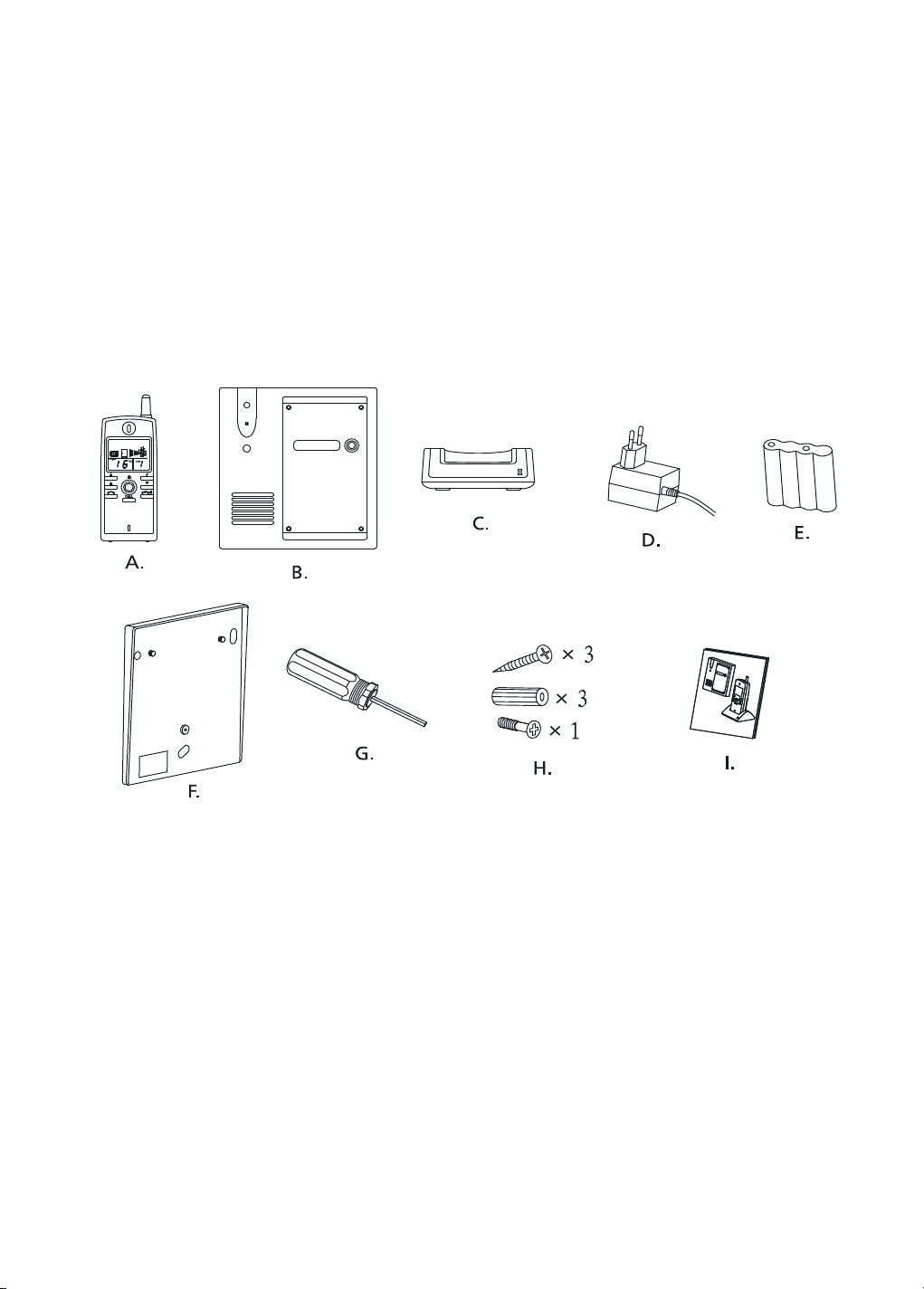
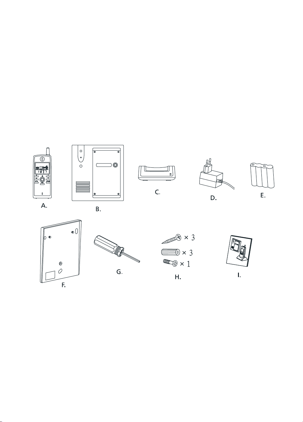
1. SET CONTENTS
A: Handset
B: Door unit
C: Docking station
D: 2 x Power adapter
E: Rechargeable Ni-MH battery set
F: Wall mounting plate for door unit
G: Special anti-theft/-sabotage tool (pentagonal)
H: Screws en plugs
I: Manual
2. PROPERTIES
• Digital technique assures a practically distortion-free signal.
• Full Duplex function.
• Range up to 150m in free field, and up to 50m through walls and ceilings.
• Choice between ringtones, visual and/or vibration alarm for the handset.
• Outside temperature indicated on handset.
• More than 65.000 code combinations guarantee high level safety, privacy and prevention
of disturbances from neighbouring systems.
4
© MARMITEK
Page 5
• Optional remote controlled electric door opener.
• Sound and visual warnings on the handset for out-of-range and battery-low, given of the
handset as well as the door unit.
• Intercom function possible between the handsets (extra handsets optionally available).
• Simple wireless installation possible.
• The door unit is supplied with an extra AUX connector which is activated when the doorbell
is pressed, and can be used to link a conventional doorbell or to switch on the lights at the
door/entrance, for example. (e.g. Marmitek X-10 www.marmitek.com )
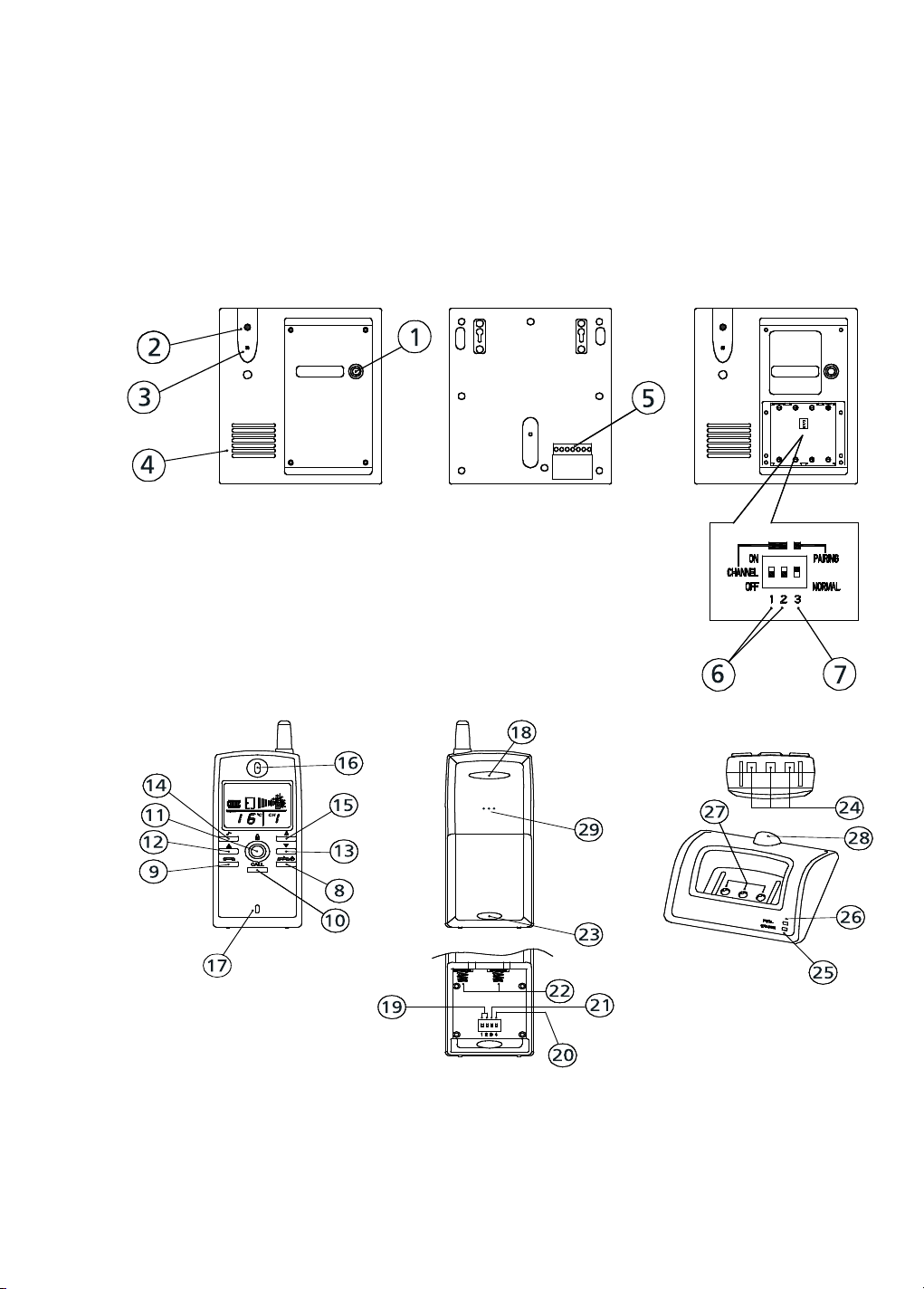
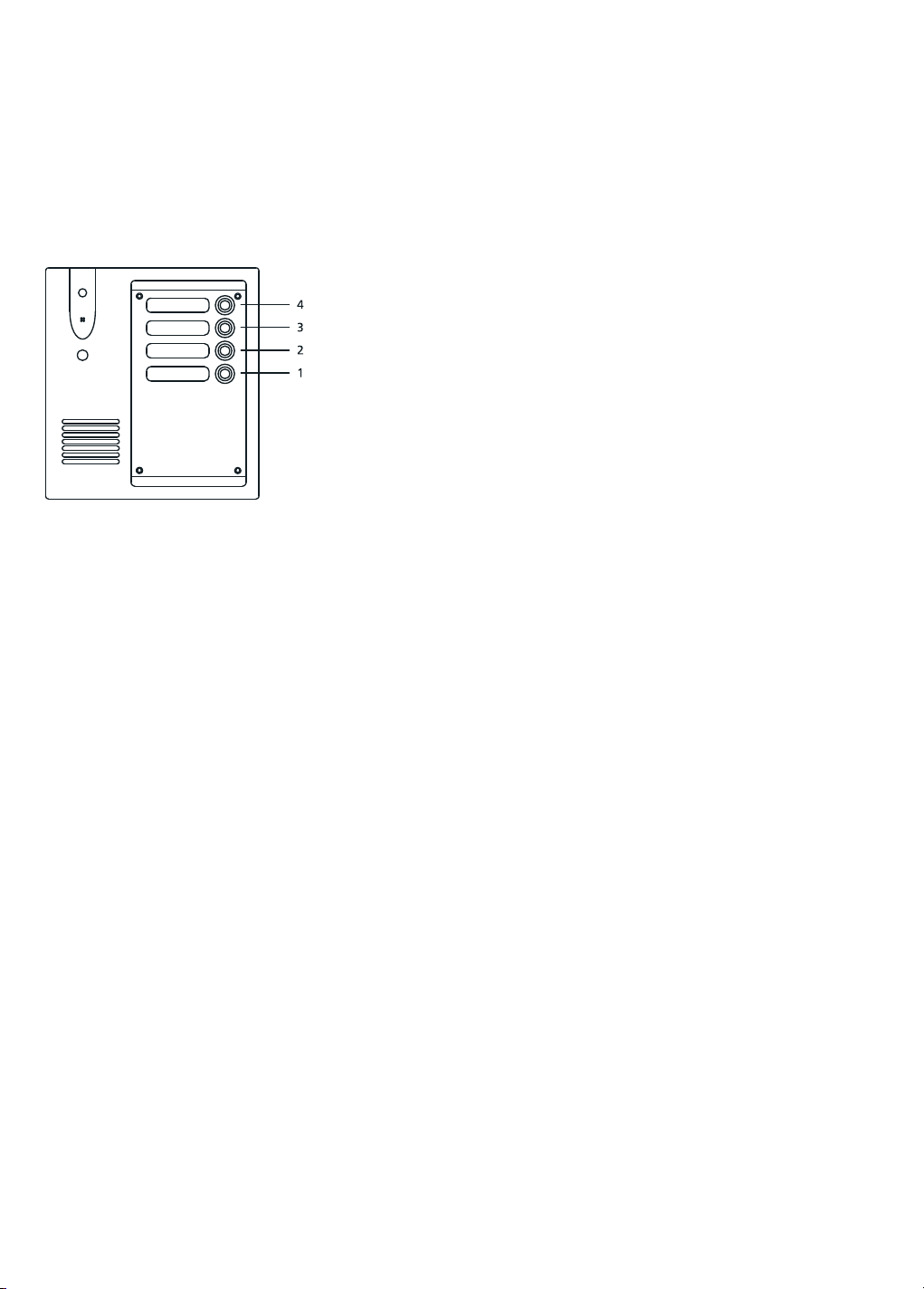
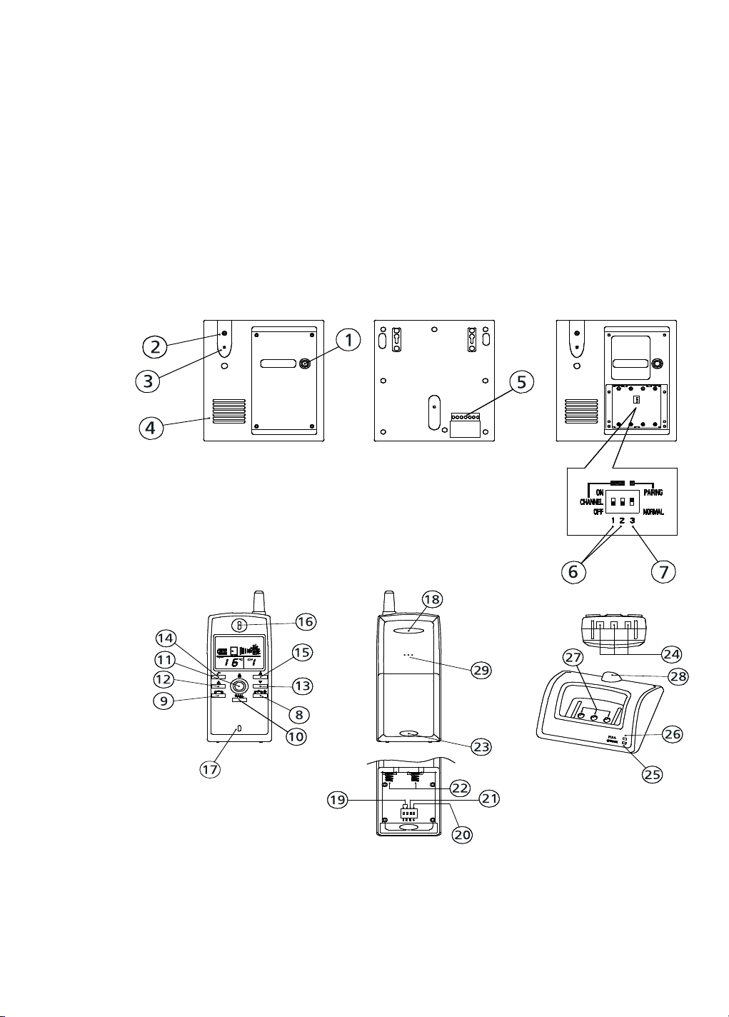
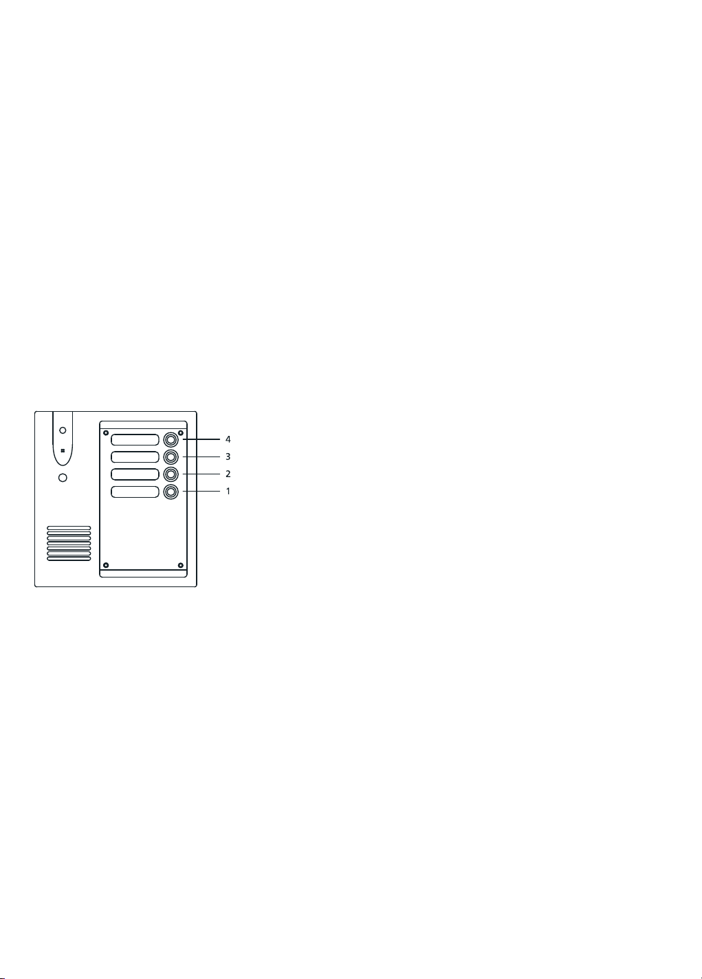
Door unit
1 Doorbell button
2 Doorbell indicator light
3 Microphone
4 Loudspeaker
5 Connectors for the electric door opener, power supply (optional), etc.
6 Channel select dipswitches (white)
7 Log-on/ ‘Pairing’ dipswitch
Handset and Docking Station
8. End conversation and on/off button 15. Ring mode button
9. Speech button 16. Loudspeaker opening
10. Call button (call another handset) 17. Microphone
11. Door-open button 18. Visual call indicator
12. Volume + button 19. Channel select dipswitch (white)
13. Volume - button 20. Door opener on/off select dipswitch (yellow)
14. Ring tones select button 21. Backdoor on/off select dipswitch (yellow)
22. Battery contact springs
23. Battery cover lock
24. Charger contacts
25. Charger indicator light
26. Battery-full indicator light
27. Charger contact points
28. Power adapter connection
29. Ringtone speaker
DOORPHONE 120™
5
Page 6
3. INSTALLATION
Before you get started with the installation, it is necessary that you fully charge the handset
(4-5 hours).
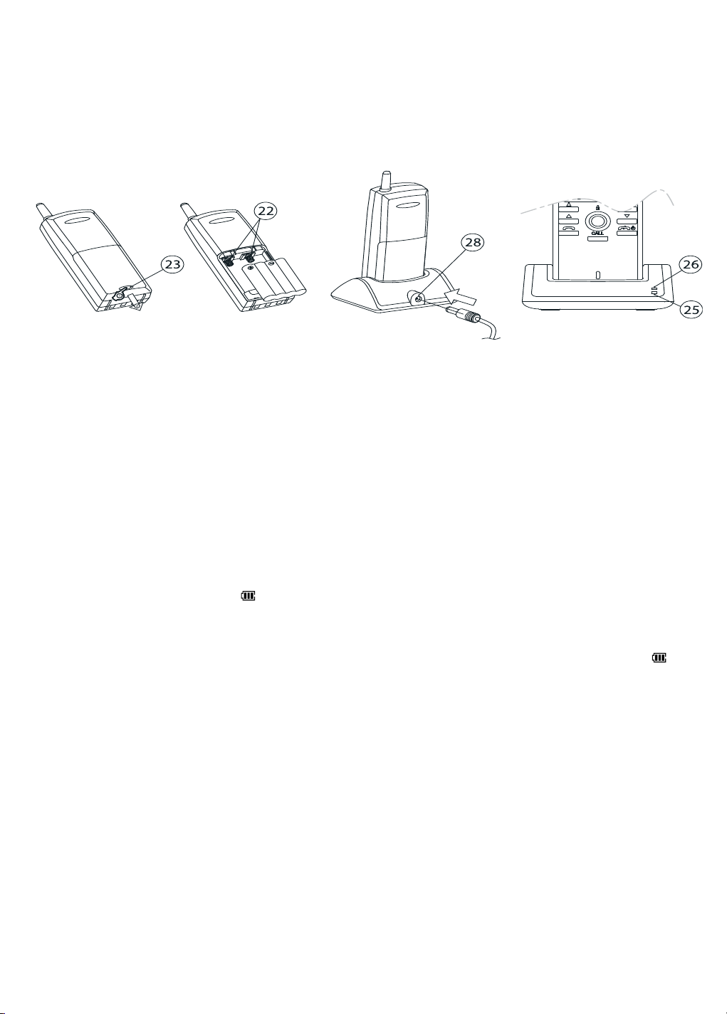
Charge handset:
A B C D
Figure 1
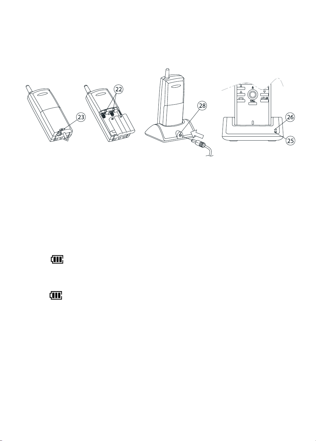
See figure 1
1. Remove the battery cover by pressing on the battery cover lock (23).
2. Insert the additionally supplied battery pack into the battery compartment. Make sure you
connect the right polarities of the battery and the handset (22).
3. Place the battery cover back onto the handset. Beware! Do not put on the handset yet.
4.
Insert the supplied power adapter into the connector at the back side of the docking station (28),
insert the electric plug into the power socket and place the handset into the docking station.
5. The red ‘Charge’ indicator light (25) and the green ‘Full’ battery indicator light (26) should
now go on and off alternately, which is to check the battery status. Shortly after that, only
the red charger indicator light (25) will keep flickering. During the charging, the battery
symbol
shall be visible in the LCD screen and the segments shall start moving to
indicate that the handset is being charged.
6. After approximately 4 till 5 hours, the battery should be fully charged and the ‘Full’ battery
indicator light (26) shall burn constantly. When the battery is fully charged, the battery
symbol
will disappear when the handset is off.
7. The handset is now ready for further installation. It is advisable that the handset be placed
in the docking station when not being used, so that it is always fully charged. This is not
damaging the battery.
Getting the set ready for installation:
The door unit needs to be set on the same channel as the handset. Check the settings and
adjust them if necessary, according to the instructions given below.
Note: - You always need to place 4 AA Penlite batteries into the door unit for start-up, even
when you will be using an external power supply (see ‘Pairing procedure’).
- In case you have more than one doorbell button on the door unit, then the channel
settings are predetermined at the factory and cannot be altered. In that case you can
skip the section ‘Channel settings door unit’.
6
© MARMITEK
Page 7
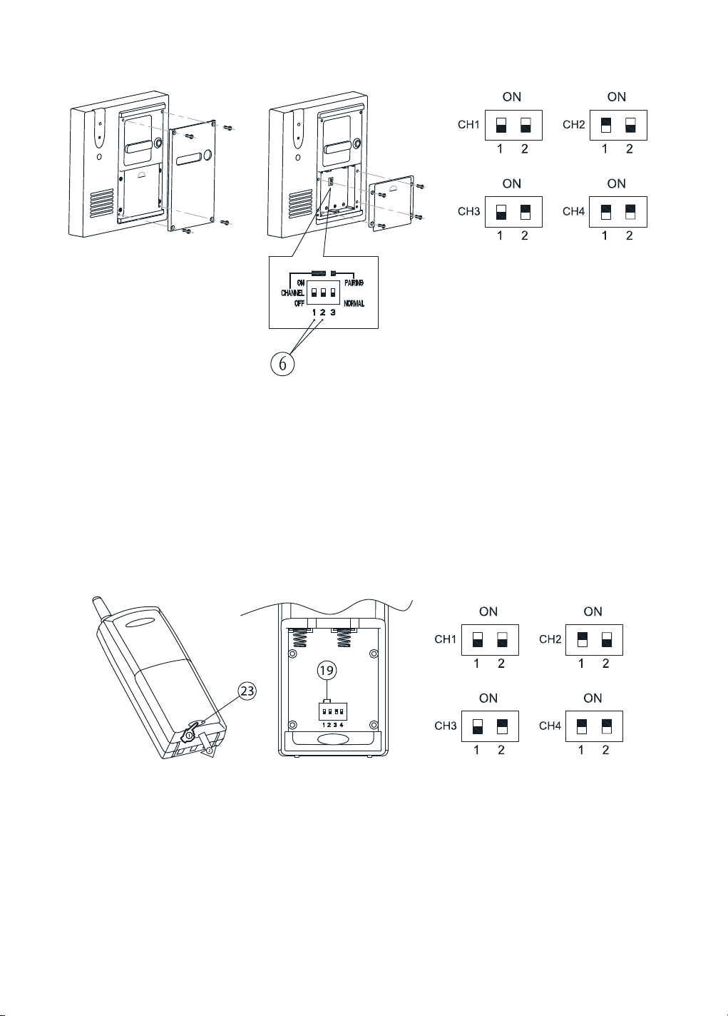
3.1
Channel settings door unit (only for door units with a single doorbell button (1)):
A B C
Figure 2
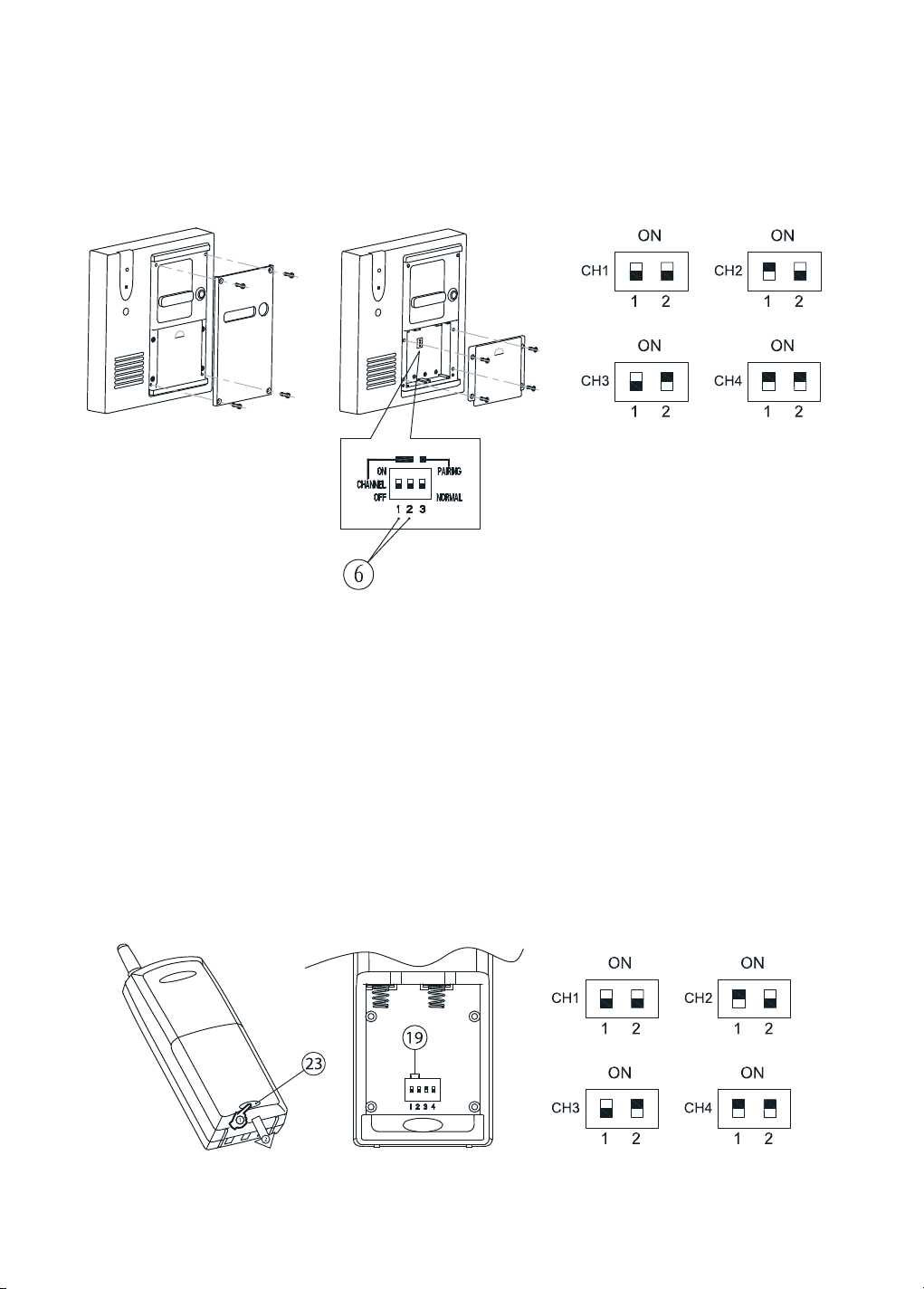
1. Loosen the 4 screws of the aluminium front panel using the supplied screwdriver. These
screws have been designed such that they can only be loosened with this special tool,
which is to prevent sabotage or theft. Keep this tool at a safe place.
2. Remove the aluminium front panel (Figure 2A).
3. Open the battery compartment by removing the rubber seal (Figure 2B).
4.
You will now see the channel select dipswitches 1 and 2 (6). You can select the desired channel
with the use of a pointed instrument such as a pen or a small screw driver (Figure 2C).
5. Dipswitch 3 shall be taken up in the next chapter.
3.2 Channel settings handset:
A B C
Figure 3
1. Remove the battery cover by pressing on the cover lock (23) and extract the battery pack
(Figure 3A).
2. You will now see the channel select dipswitches 1 and 2 (19). You can now select the desired
channel with the use of a pointed instrument such as a pen or a small screw driver.
3. Set the dipswitches on the same position as that of the door unit (Figure 3C). Beware!
Wrong settings will result in the failure of the handset and door unit to communicate with
each other. Dipswitch 3 should always be set on the ‘OFF’ position. Dipswitch 4 will be
taken up later on.
DOORPHONE 120™
7
Page 8
4. Place the supplied battery pack into the battery compartment. Be careful about using the
right polarity of the batteries and the handset (22) and place the battery cover back onto
the handset.
In case you are using the handset(s) in combination with a 4-doorbells door unit, then you can
set the handsets on channel 1, 2, 3 and 4 respectively. They should correspond with the door
unit switches 1, 2, 3 and 4.
4. Pairing the handset(s) to the door unit:
The pairing procedure is essential for the set to function. Every door phone system is provided
with a unique identity code (ID), so that only the handset and the door unit can communicate
with each other. There are more than 65.000 different code combinations, so that the chance
that someone else in your area has the same code is extremely small.
Beware! It is necessary for the pairing procedure that the alkaline batteries in the door unit be
fully loaded. In case the external power supply has already been connected to the door unit,
then disconnect the power supply for the pairing procedure.
8
© MARMITEK
Page 9
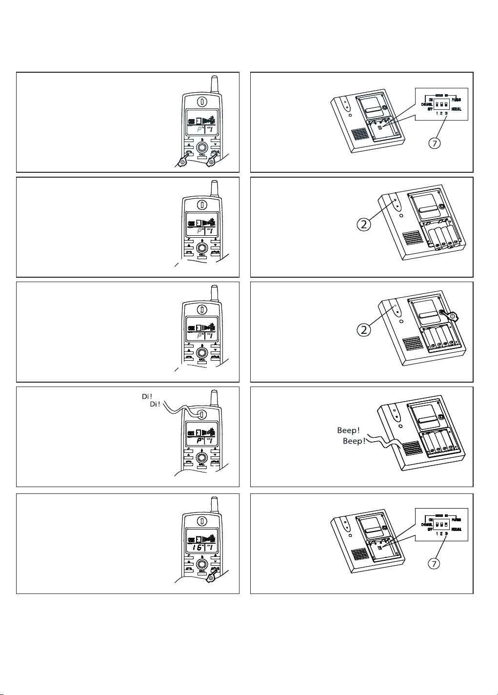
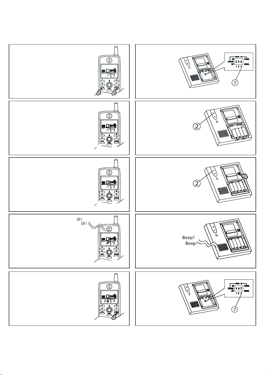
Follow the 5 steps given below for the pairing of the handset to the door unit.
Handset
Step 1
Press and hold the buttons (8) and (9)
at the same time for a few seconds
to put on the handset. You will now
hear a short beep. Release (8) and (9)
buttons and you will hear a 2nd beep
as confirmation.
Step 2
Step 3
Door unit
Set the dipswitch 3
on the ‘Pairing’
position (7).
Place 4 AA-alkaline
batteries, keep in mind
the right poles + and -.
The doorbell indicator
light (2) shall now burn
constantly.
Now press on the
doorbell button (1) and
the ‘Bell’ light will start
flickering. A random
ID code is now being
generated and sent to
the handset.
Step 4
The ‘P’ symbol will stop
flashing when the ID code has
been received.
Step 5
After you hear the two confirmation
beeps of the door unit, press on
button (8) to go back to the normal
display.
Within 10 seconds,
the unit will beep
twice to indicate
that the handset has
received the ID code.
Take out the
batteries and put
the dipswitch (7)
back to the
‘Normal’ position.
The pairing procedure has now been completed. To test the pairing function, place the
batteries back into the door unit and press on the doorbell button (1). The handset should
respond now.
DOORPHONE 120™
9
Page 10
If after you have logged on and you hear interference coming from other wireless devices in
the neighbourhood, such as a mobile phone, then repeat the above mentioned procedure or
switch over to another channel (when you change the channels, you will need to repeat the
pairing procedure).
When the pairing has not been successful (the ‘P’ symbol on the LCD screen will flicker),
then put off the handset and disconnect the power supply of the door unit by removing the
batteries. Repeat the pairing procedure.
4.1 Copying the ID code to an extra handset:
Beware! In case you have more than one handset, always first perform the pairing procedure
with one handset only. Use the logged-on handset to copy (‘clone’) the ID to the extra
handset(s). Every time you add an extra unit to the system, you need to copy the ID code to it;
otherwise the system will not function properly.
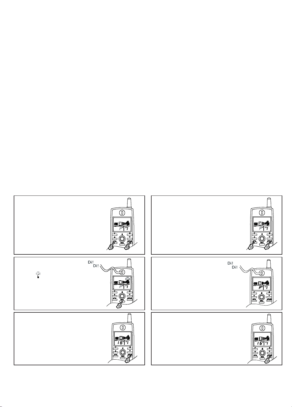
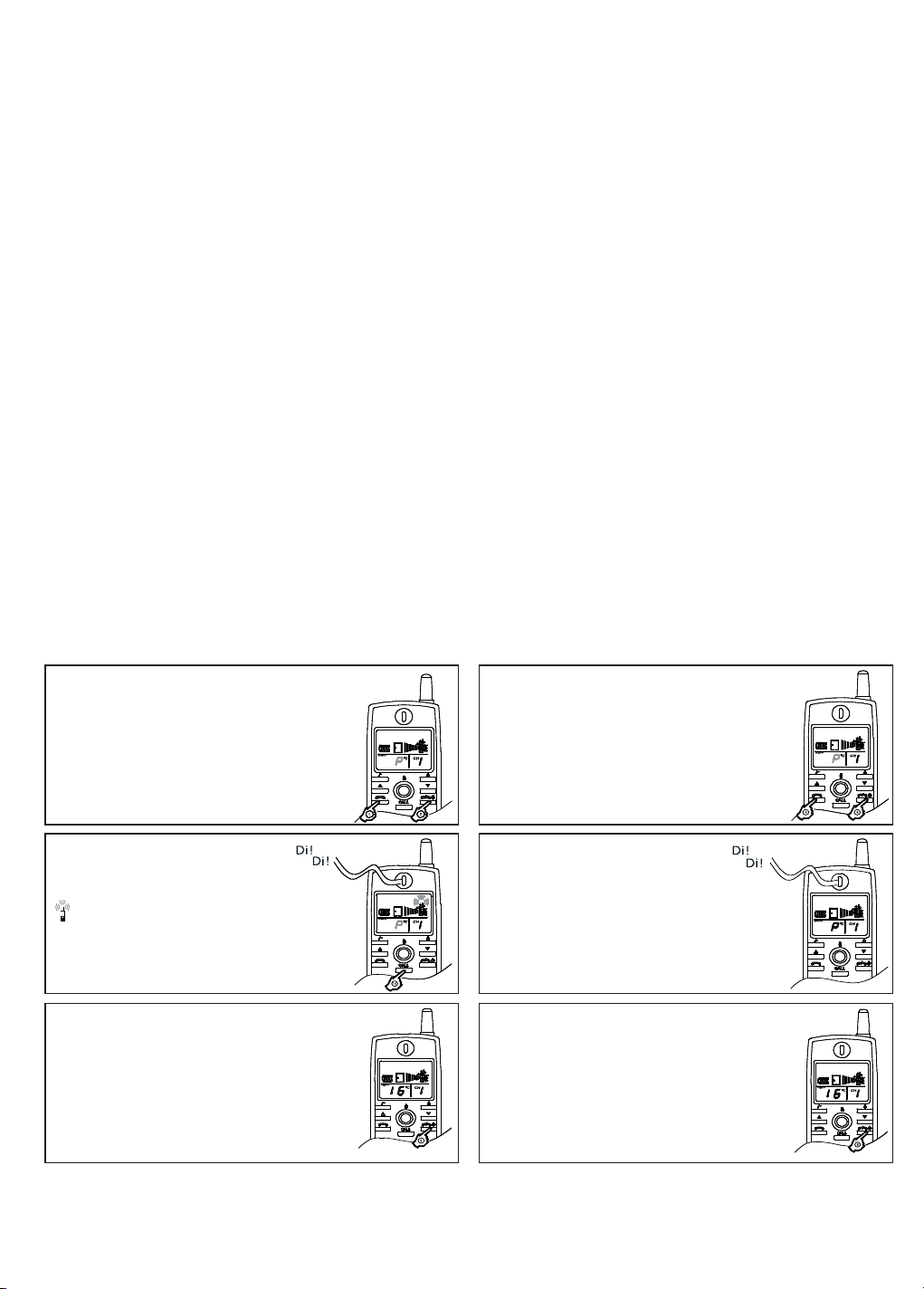
Follow the steps given below to copy the ID code onto an extra handset.
Make sure that the extra (‘Slave’) handset has been switched to the same channel as the primary
(‘Master’) handset (see chapter 3.2:’Channel settings handset’). Tip! All ‘Slave’ handsets can be
cloned to the ‘Master’ handset at the same time.
Logged-on handset ‘Master’ To be cloned handset ‘Slave’
Step 1
Press and hold the buttons (8) and (9)
at the same time for a few seconds
to put on the handset. You will now
hear a short beep. Release (8) and (9)
buttons and you will hear a 2nd beep
as confirmation. You will see a ‘P’
flashing in the display.
Step 2
Press on the call button (10) a
symbol
display. The saved ID code is
now being sent.
Step 3
Now press briefly on the on/off
button (8) to return to the normal
display.
will appear on the
Step 1b
Press and hold the buttons (8) and (9)
at the same time for a few seconds
to put on the handset. You will now
hear a short beep. Release (8) and (9)
buttons and you will hear a 2nd beep
as confirmation. You will see a ‘P’
flashing in the display.
Step 2b
The ‘P’ shall stop flashing within
5 seconds after the ‘Slave’ handset
has received the ID code, and will
beep twice briefly to indicate that
the cloning has been completed.
Step 3b
Now press briefly on the on/off
button (8) to return to the normal
display.
To activate the temperature reading, the batteries need to be removed from the door unit for
the duration of 5 seconds.
10
© MARMITEK
Page 11
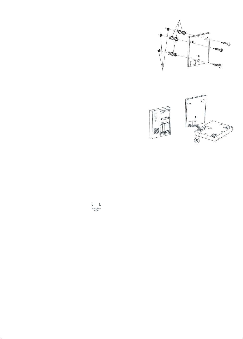
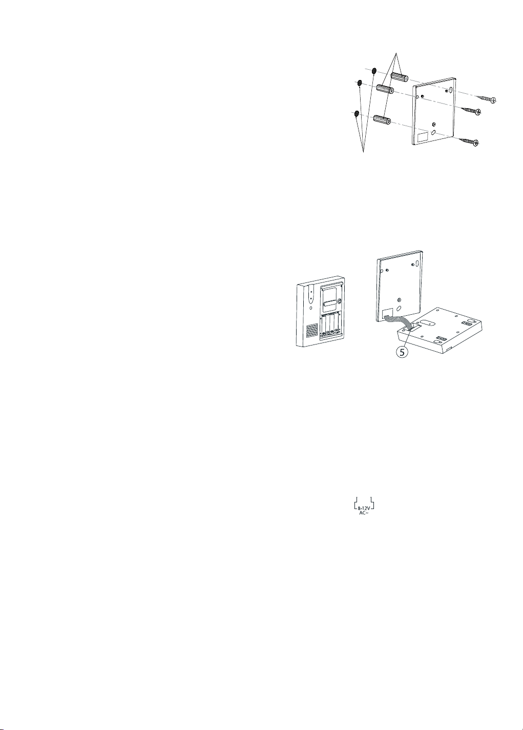
5. INSTALLING THE DOOR UNIT
Insert riverts into holes
(for concrete walls only).
• Decide the best place for the installation of the door
unit. The attachment surface should be as flat as
possible; otherwise the unit will not fit properly onto
the wall plate.
• It is advisable not to install the unit onto a metal
surface or near other possible sources of interference,
which could have negative influence on the system.
• Mark the spots to drill holes at, by making use of
Driled holes
Figure 4
the holes in the plate, as shown in figure 4, and
attach the plate to the wall. You can use the supplied
screws and plug for the attachment of the plate.
Figure 5
5.1 Connecting the power supply to the door unit:
The door unit can be powered in two ways.
1. Using batteries. (power failure)
2. Using external power adapter.
1. Using batteries:
Insert 4 AA-alkaline batteries, keep in mind the right polarity + and -, in relation to the
contact springs in the battery compartment. Use only new full alkaline batteries for reliable
function (do not use rechargeable batteries).
2. Using external power adapter:
It is also possible to connect the door unit to the supplied external power. Connect the
wires of the power adaptor to the connectors (terminals) at the backside of the door unit
(5), these are marked with the
symbol. When there are also batteries present in the
door unit, then the batteries take over the function in case of power failure. Check the
condition of the batteries regularly. Replace old batteries immediately. When an external
power adapter is connected, the name illumination on the door unit will get activated
automatically when it gets dark outside.
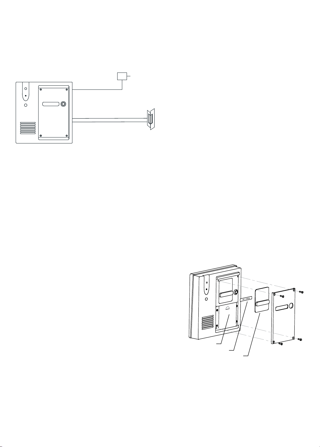
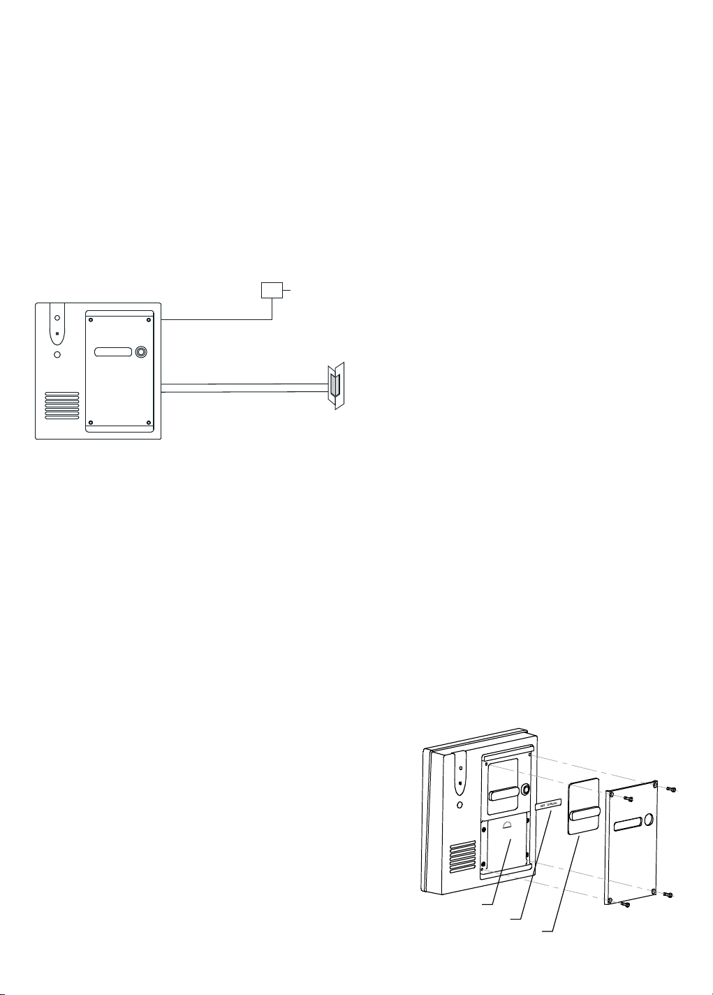
5.2 Connecting an electric door opener (optional):
• It is necessary for the installation of the electric door opener, that the door unit will be
supplied with external power; otherwise the door-open function will not be active and
therefore not usable.
• There are different connectors (terminals) on the backside of the door unit, for the
installation of the door opener (maximum load 12V/1A). The voltage on these connectors is
the same as that of the connected power adapter.
1. A, B: 8~12V normally, 0V when triggered.
2. A, C: 0V normally, 8~12V when triggered.
DOORPHONE 120™
11
Page 12
The electric door opener can be connected directly to the door unit of the Doorphone120
system (A,C); in this case the door opener is supplied by the door unit. Maximum load 12V/1A
(additionally supplied power adapter 12VDC/600mA).
> See the specifications of your electric door opener, to choose the socket and power supply.
Max. 12V/1A (12V/600mA supplied).
Max. 12V/1A
5.3 Use of AUX function (voltage-free/potential-free contact):
The door unit is provided with an extra AUX connector (5) which gets activated when the
doorbell button (1) is pressed. Among other functions, this can be used for the activation
of an (existing) conventional doorbell (1) or for switching on the lights in the door/entrance
(maximum load 12V/200mA).
• Now that the door unit is connected, the wall mounting plate can be installed. Remove the
batteries, place the door unit onto the metal nugs, and slide the unit upwards. Hold the unit
firm in its place and screw it onto the mounting plate with the use of the cross-head screws
in the battery compartment (Figure 7).
• Check if the Log-on dipswitch (7) is on the ‘Normal’ position and place the batteries back.
• Before you put back the rubber seal
and the aluminium cover plate, you may
want to put your name on the supplied
name tag.
• Install the cover back as illustrated in
figure 7. Make sure that the rubber seal is
placed properly back onto the unit. Failing
proper installation of the rubber seal will
hinder the proper closure of the rest of
the parts, thereby affecting the function
and the lifespan of the unit.
Rubber seal
Name plate
Name plate cover
Figure 7
The door unit is made of an impact-resistant ABS/PC plastic and reinforced by an aluminium
front panel. This door unit is extremely suitable for the most common outdoor situations.
12
© MARMITEK
Page 13
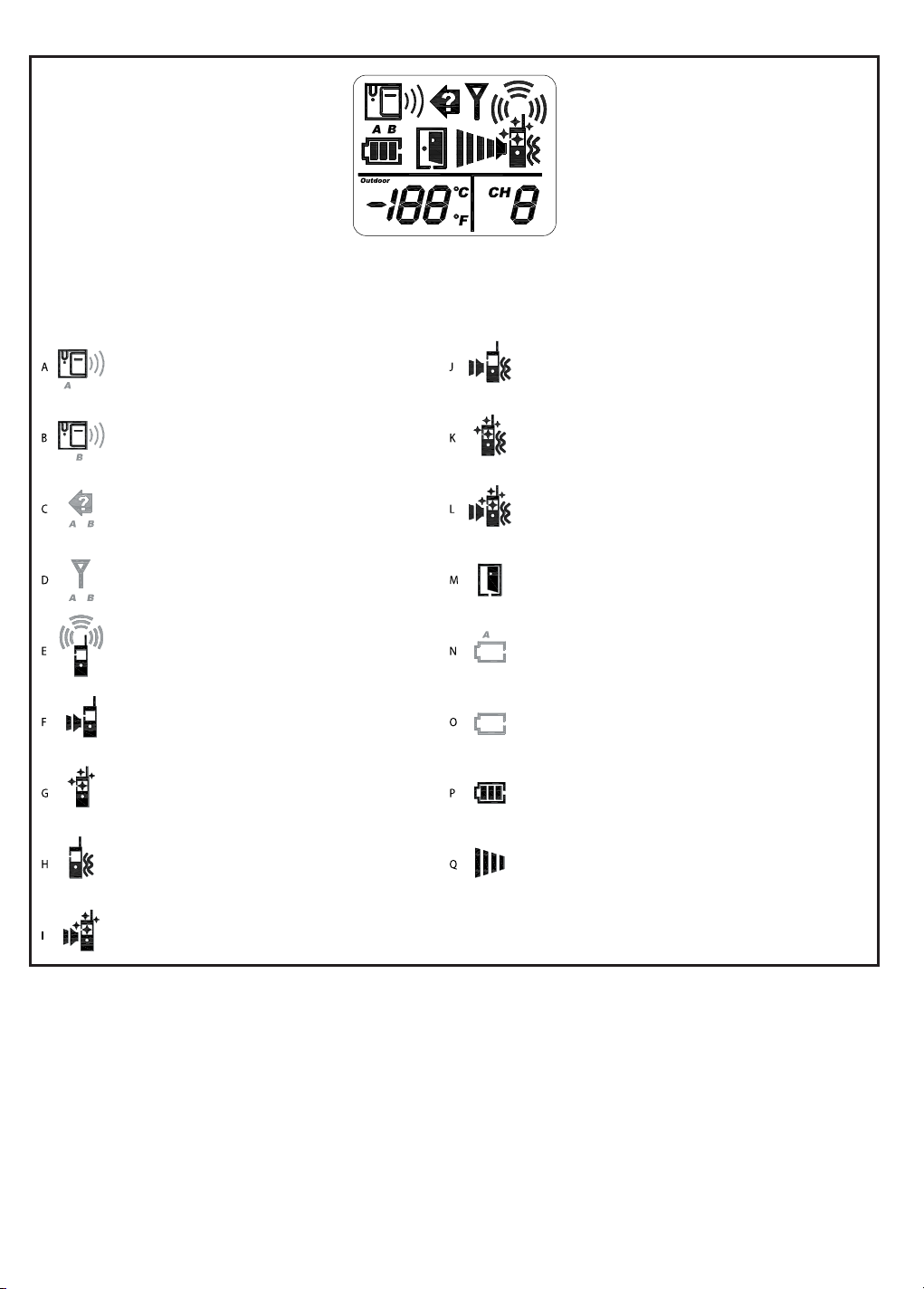
LCD Icons
Light up constantly - flickering
Icon Status Icon Status
Someone is at the front door
Someone is at the back door
Missed call
Out of range
Line busy
Ringtone selected
Bell illumination selected
Vibration function selected
Ringtone and vibration selected
Illumination and vibration selected
Ringtone, illumination and vibration
Door opener
Battery low external unit
Battery low handset
Battery level
Volume
Ringtone and illumination selected
6. APPLICATION
• Switch the handset on or off by keeping the on/off button (8) pressed and held for
approximately 3 seconds.
• When switched on, the LCD screen shall illuminate.
•
Now press the doorbell button (1) of the door unit. You will hear the ring tone and the door
bell indicator light (2) will go on. The doorbell indicator light shall stay on until the handset is
answered or the call is cancelled. When the handset is not answered, the door unit will stop
calling automatically after 40 seconds and the doorbell indicator light will go off.
DOORPHONE 120™
13
Page 14

• As soon as the handset is answered, the door unit doorbell indicator light (2) shall
burn constantly. The caller can communicate by speaking into the microphone (3).
To prevent echo, there is a hands-free function built in, which makes sure that when a
visitor speaks into the microphone (3) of the door unit, the loudspeaker (4) shuts off.
Beware! This means when the visitor is speaking into the microphone, he will not be able
to hear you, therefore wait with answering until the visitor has finished speaking.
• When receiving a call from the door unit, the symbol
can answer the call by pressing on the speech button (9). At the same time the symbol
will appear on the display. From this moment on, it is possible to speak to the visitor.
• Beware! The system has a built-in conversation time limit of 60 seconds, which is for if you
forget to break the connection after a conversation has ended. When you are reaching this
time limit, you shall hear a signal tone. If required, you can extend the conversation time by
another 60 seconds by pressing on the speech button (9). There is no limit to the amount
of times you can extend the conversation.
•
In case you have also connected an electric door opener, you can open the door during the
conversation by briefly pressing on the door-open button (11). After approximately 4-5 seconds,
the symbol
use of the Door open on/off dipswitch (20) on the handset. Furthermore, the door can only be
opened when there is a connection between the handset and the door unit.
will appear on the LCD screen. This function can be switched on or off with the
shall appear on the display. You
7. SPECIAL FUNCTIONS
• Ringtones; use the button (14) to choose the desired ringtone.
• Ring mode; use the button (15) to select the ring mode. Depending on your selection,
symbols (F till L) will appear on the screen. Note; in case you select a combined function,
the battery will need to be charged more often, at the cost of the battery’s lifespan.
• Loudspeaker volume; using the buttons (12-13), you can adjust the loudspeaker volume
of the receiver (16) during a conversation.
• Extra door unit; this function is not active. Make sure that the yellow backdoor on/off
select dipswitch (21) is on the ‘OFF’ position. A wrong setting can result in a false notice
‘Out of range’.
• Not home; when you have not answered a call from the door unit, the symbol
appear on the LCD screen. This symbol will alert you of the fact that someone has been at
the door. Pressing on the on/off button (8) will make the symbol disappear.
• Out of range; when your handset is beyond the reach of the door unit, you will hear a
signal and the symbol
as soon as you are out of range but rather when you are out of range for over 30 minutes.
Pressing the on/off button (8) will stop the alarm temporarily, but the symbol
displayed. As soon as you are within reach of the door unit, the alarm will stop and the
symbol will disappear.
This signal will also appear when the batteries of the door unit are low, and if the external
power supply fails or if the switch for the extra door unit is on the ‘ON’ position while there
is no extra unit installed.
will appear on the display. Beware; this notice will not be activated
will remain
will
14
© MARMITEK
Page 15
• Battery life; in case of power cut, the batteries of the door unit should last approximately
5-6 weeks. This depends on the use of the system. When the batteries are low, the symbol
shall appear on the display and a signal will be heard. Pressing the on/off button (8) will
stop the signal temporarily, but the symbol
will remain displayed.
• Outside temperature; The outside temperature is displayed on the handset. During the
installation of the door unit, the temperature will not be displayed on the handset, but after
the installation is done, the temperature will appear.
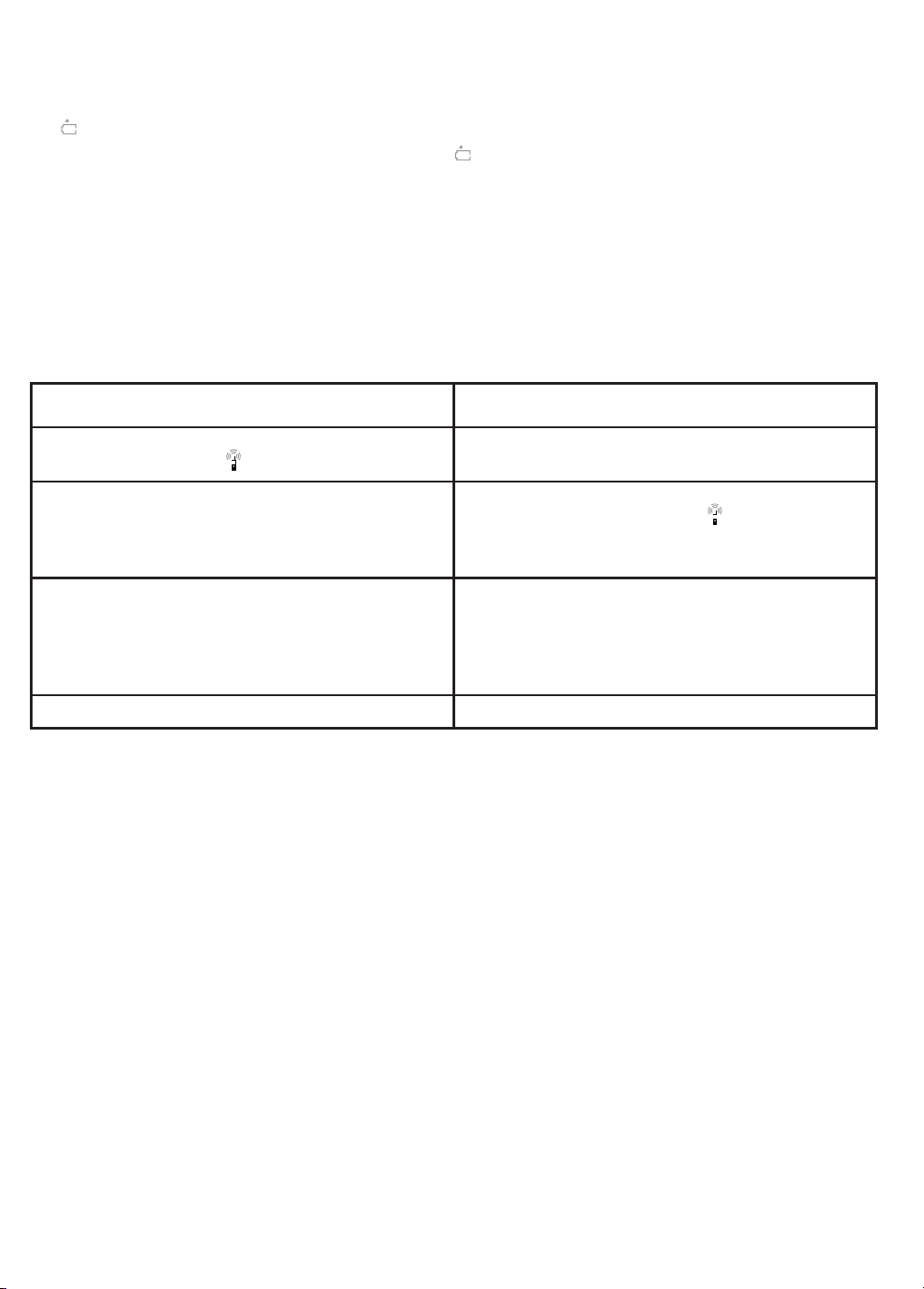
8. INTERCOM
This function applies only with the use of 2 or more handsets. In that case it is necessary that
all handsets are set to the same channel and have the same ID code (see ‘Cloning’).
Calling handset Receiving handset(s)
Press on the ‘Call’ button (10) and you will hear the
ringtone, also the symbol
Ringtone stops when the call in answered, you may speak
now. If no one answers, the ringtone will stop after 20
seconds.
The conversation time is limited to 30 seconds, when
reaching the end of this limit you will hear a beep. You can
extend this time limit by another 30 seconds by pressing
the speech button (9). There is no limit to the amount of
times you can extend the time limit.
End the conversation by pressing on the on/off button (8). End the conversation by pressing on the on/off button (8).
will appear.
When receiving the call, the ringtone will be heard.
Press on the speech button (9) to answer the call. The
ringtone will stop and the symbol
now start to converse. You can also choose to press the
on/off button (8) to ignore the call.
Conversation period cannot be extended with the receiving
handset.
will appear, you can
Calling selectively with a handset is not possible. When a handset makes a call, all other
handsets (that are set to the same channel) will ring and can answer the call. The first handset
that answers the call by pressing the speech button (9) will block all other handsets, and these
will not be able to receive the call.
Beware! When two handsets are in conversation, it will not be possible to receive a call from
the door unit.
9. FREQUENTLY ASKED QUESTIONS
Handset and door unit are not communicating
• The ID code is not set correctly. Repeat the pairing procedure.
• The channels are not synchronised. Set the handset and the door unit on the same channel
and then repeat the pairing procedure.
• The batteries are low. Replace the door unit batteries or charge the handset.
• The yellow log-on dipswitch (7) on the door unit is still on ‘Pairing’. Repeat the pairing
procedure and set the switch to the normal position.
DOORPHONE 120™
15
Page 16

Range is reducing
• There are too many interfering sources (e.g. metal constructions) between the handset and
the door unit. Place the handset at a different place for a stronger signal.
• The batteries are low. Replace the door unit batteries or charge the handset.
Out of reach indicator is always on
• The door unit is not getting powered. Replace the batteries or check the power adapter of
the door unit.
• The back door on/off select dipswitch (21) is set on the ‘ON’ position. Set the dipswitch on
‘OFF’.
Electric door opener is not functioning
• The Door open on/off select dipswitch (20) is set on the ‘OFF’ position. Set the dipswitch on
‘ON’.
• You haven’t used a power adapter for the door unit. Connect the power adapter.
• The connecting clamps are incorrectly connected. Connect them correctly.
The electric door opener sometimes functions and sometimes not.
• When you operate the electric door opener, in the display next to the battery indicator you
will see the symbol of a closed door. Please do not hang up until you see that this symbol
has changed into an open door.
Intercom is not functioning
• The ID code is not cloned correctly to the other handsets. Repeat the cloning procedure.
• The battery is (almost) empty. Charge the battery of the handset.
• The different handsets are set to different channels. Set the handsets on the same channel
and repeat the cloning procedure.
Do you still have questions, please check out www.marmitek.com
10. TECHNICAL DATA
Handset
Power: 4,8v Ni-mH battery set
Charger: 9V 300mA
Power consumption: Stand-by 25 mA
Active 50 mA
Bell sound: 3 Programmable tunes
Channels: 1,2,3,4.
Dimensions: 52x142x32mm
Door unit
Range Up to 150m in free field,
up to 50m through walls and ceilings
Power Battery (4x AA alkaline)
16
© MARMITEK
Page 17

Power adapter 12 VDC, 600mA (supplied)
Frequency 863-865Mhz
Power consumption Stand-by 2 mA
Active 160 mA
Material ABS / PC / Aluminium
Connection External power 8-12V MAX 1A
Make connection 8-12V MAX 1A
Break connection 8-12V MAX 1A
AUX connector MAX 12V/200mA
Ambient temperature: - 10° C to + 60° C
IP value IP54
Dimensions 150x158x35mm
11. OPTIONAL ACCESSORIES
Extra handset; article no. 09739.
You can link more handsets to one door unit. When using it in combination with the 4-rings
door unit, every doorbell button that you use will need its own handset. You can also link more
than one handset on a single doorbell button. You can also communicate (intercom function)
with each other using the handsets that are linked to only one doorbell button. For more
information see www.marmitek.com.
Environmental Information for Customers in the European Union
European Directive 2002/96/EC requires that the equipment bearing this symbol on the product and/or its
packaging must not be disposed of with unsorted municipal waste. The symbol indicates that this product should
be disposed of separately from regular household waste streams. It is your responsibility to dispose of this and
other electric and electronic equipment via designated collection facilities appointed by the government or local authorities.
Correct disposal and recycling will help prevent potential negative consequences to the environment and human health. For
more detailed information about the disposal of your old equipment, please contact your local authorities, waste disposal
service, or the shop where you purchased the product.
DOORPHONE 120™
17
Page 18

18
© MARMITEK
Page 19

DOORPHONE 120™
WIRELESS DOORPHONE
SICHERHEITSHINWEISE
• Um Kurzschluss vorzubeugen, der Handset bitte nur in trockenen Räumen nutzen. Setzen
Sie die Komponenten nicht Regen oder Feuchtigkeit aus.
• Setzen Sie die Komponente Ihres Systems nicht extrem hohen Temperaturen oder starken
Lichtquellen aus.
• Bei einer zweckwidrigen Verwendung, selbst angebrachten Veränderungen oder selbst
ausgeführten Reparaturen verfallen alle Garantiebestimmungen. Marmitek übernimmt
bei einer falschen Verwendung des Produkts oder bei einer anderen Verwendung des
Produktes als für den vorgesehenen Zweck keinerlei Produkthaftung. Marmitek übernimmt
für Folgeschäden keine andere Haftung als die gesetzliche Produkthaftung.
• Dieses Produkt ist kein Spielzeug. Außer Reichweite von Kindern halten.
• Das Produkt niemals öffnen (ausgen.des Batteriefachs): Das Gerät kann Teile enthalten,
worauf lebensgefährliche Stromspannung steht. Überlassen Sie Reparaturen oder Wartung
nur Fachleuten.
• Halten Sie die Batterien außerhalb der Reichweite von Kindern. Liefern Sie die Batterien als
chemischen Kleinabfall ein. Verwenden Sie niemals alte und neue oder unterschiedliche
Typen von Batterien durcheinander. Wenn Sie das System längere Zeit nicht benutzen,
entfernen Sie die Batterien. Achten Sie beim Einlegen der Batterien auf die Polarität (+ / -):
Ein falsches Einlegen kann zu Explosionsgefahr führen.
• Schließen Sie den Netzadapter erst dann an das Stromnetz an, nachdem Sie überprüft
haben, ob die Netzspannung mit dem auf dem Typenschild angegeben Wert übereinstimmt.
Schließen Sie niemals einen Netzadapter oder ein Netzkabel an, wenn diese beschädigt
sind. In diesem Fall nehmen Sie Kontakt mit Ihrem Lieferanten auf.
INHALTSÜBERSICHT
EINF ÜHRU NG _______________________ 20
1. VERPAKKUNGSINHALT ___________ 20
2. EIGENSCHAFTEN ________________ 20
3. INSTALLATION __________________ 21
3.1 Kanaleinstellung Außeneinheit (nur für
die Einstellung einer Außeneinheit mit
einer Klingel (1)) _________________ 23
3.2 Kanaleinstellungen Handsets ______ 23
4. ANMELDEN (PAIRING) DES/DER HAND SETS UND DER AUßENEINHEIT _____ 24
4.1 ID Kode auf ein extra
Hands et kopieren ________________ 26
5. MONTAGE DER AUßENEINHEIT ____ 27
DOORPHONE 120™
5.1 Anschließen der Speisung für die
Außeneinheit ___________________ 27
5.2 Anschluss eines elektrischen
Türöffners (optional) _____________ 27
5.3 Anwendung der AUX
Funktion (spannungsfreier/
potenzialfreier Kontakt) ___________ 28
6. A N W EN DU NG __________________ 29
7. SPEZIALFUNKTIONEN ____________ 30
8. WECHSELSPRECHANLAGE ________ 31
9. HÄUFIG GESTELLTE FRAGEN ______ 32
10. TECHNISCHE DATEN _____________ 33
11. OPTIONELL ERHÄLTLICH __________ 33
19
Page 20
EINFÜHRUNG
Herzlichen Glückwunsch zum Erwerb des Marmitek DoorPhone120™, dem digitalen, drahtlosen
Türtelefon. Mit diesem Türtelefon können Sie an jedem gewünschten Ort im oder ums Haus
herum (bis zu 150m) mit demjenigen, der vor Ihrer Tür steht, sprechen. Wenn Sie einen
elektrischen Türöffner montieren, können Sie sogar die Tür drahtlos und fernbedient öffnen.
Sie können mehrere Handsets an Ihre Außeneinheit koppeln. Bei kombinierter Verwendung
mit der 4-Klingel Außeneinheit benötigt jede Türklingel, die Sie benutzen möchten, ein
eigenes Handset. Auch können Sie mehrere Handsets an eine Türklingel koppeln. Mit den
an eine Türklingel gekoppelten Handsets können Sie zudem wechselseitig kommunizieren
(Wechselsprechanlagefunktion). Für optimalen Bedienungskomfort und Funktionstüchtigkeit
ist es wichtig, dass Sie diese Gebrauchsanleitung aufmerksam durchlesen und die Anweisungen
befolgen. Zur Durchführung der Installation benötigen Sie 4 x AA Batterien.
1. VERPAKKUNGSINHALT:
A: Handset
B: Außeneinheit
C: Ladestation
D: 2x Speisungsadapter
E: Aufladbarer Ni-mH Akkupack
F: Wandmontageplatte für die Außeneinheit
G: Spezialwerkzeug Anti-Diebstahl/Sabotage (5-eckig)
H: Schrauben und Dübel
I: Gebrauchsanleitung
2. EIGENSCHAFTEN
• Digitaltechnik trägt Sorge für einen nahezu störungsfreien Betrieb.
• Full Duplex Funktion.
• Reichweite bis zu 150m im freien Feld und bis zu 50m durch Wände und Decken.
• Wählbare Melodien, visueller und/oder Vibrieralarm für das Handset.
• Außentemperaturanzeige auf dem Handset.
20
© MARMITEK
Page 21
• Über 65.000 Code-Kombinationen garantieren ein Höchstmaß an Sicherheit, Privatsphäre
und verhindern Störungen benachbarter Systeme.
• Fernbedienung eines optional erhältlichen elektrischen Türöffners.
• Ton- und Bildwarnung auf dem Handset für Reichweiteüberschreitung und leere Batterie
von sowohl dem Handset wie der Außeneinheit.
• Wechselsprechbetrieb zwischen den Handsets möglich (extra Handsets optional
erhältlich).
• Einfache Installation ohne Verdrahtung möglich.
• Die Außeneinheit ist mit einem zusätzlichen AUX Anschluss versehen, der schaltet, wenn
die Türklingel betätigt wird, zum Beispiel zur Steuerung einer (bereits anwesenden)
konventionellen Türklingel oder zum Schalten von Beleuchtung an der Tür/ am Eingang.
(z.B. Marmitek X-10 www.marmitek.com)
1 Türklingel
2 Türklingelanzeige
3 Mikrofon
4 Lautsprecher
5 Schraubkontakte zum Anschließen von u.a. einem elektrischen Türöffner und Speisung (opt).
6 Kanal Wahlschalter (weiß)
7 Anmeldeschalter “Pairing” (gelb)
8. Gespräch beenden und Ein/Aus-Taste 15. Klingelmodustaste
9. Sprechtaste 16.Lautsprecherspalte
10. Klingel (ein anderes Handset aufrufen) 17. Mikrofon
11. Türöffnertaste 18. Visuelle Klingelanzeige
12. Lautstärke + Taste 19. Kanal Wahlschalter (weiß)
13. Lautstärke - Taste 20. Türöffner Ein/Aus Wahlschalter (gelb)
14. Klingelmelodie Wahltaste 21. Hintertür Ein/Aus Wahlschalter (gelb)
DOORPHONE 120™
22. Batteriekontaktfeder
23. Batteriefachverriegelung
24. Ladekontakte
25. Ladeanzeige LED
26. Batterie-Voll-Anzeige LED
27. Ladekontakte
28. Speisungsadapter Anschluss
29. Klingelmelodie Lautsprecher
21
Page 22
3. INSTALLATION
Vor Installationsbeginn muss dass Handset für eine Mindestdauer von 4 – 5 Stunden aufgeladen
werden.
Handset laden: Abbildung 1
A B C D
Siehe Abbildung 1
1. Entfernen Sie den Batteriedeckel indem Sie auf den Deckelverschluss (23) drücken.
2. Legen Sie den mitgelieferten Akkupack in das Batteriefach. Achten Sie dabei auf die richtige
Polarität des Akkupacks und die des Handsets (22).
3. Bringen Sie den Batteriefachdeckel wieder an. Achtung! Das Handset nicht einschalten.
4. Stecken Sie den mitgelieferten Speisungsadapter in den sich auf der Rückseite des
Handsethalters (28) befindenden Anschluss, stecken Sie den Stecker in die Steckdose und
stellen Sie das Handset in den Handsethalter.
5. Die rote “Charge” Ladeanzeige LED (25) und die grüne “Full” Batterie-Voll-Anzeige LED (26)
müssen nun abwechselnd an- und ausgehen um so den Batteriestatus zu kontrollieren. Nach
kurzer Zeit wird nur die Ladeanzeige LED(25) weiter blinken. Während des Ladevorgangs
wird das Batteriesymbol
als Zeichen, dass das Handset aufgeladen wird.
6. Nach ca. 4 bis 5 Stunden werden die Batterien vollständig aufgeladen sein und bleibt die
“Full” Batterie-Voll-Anzeige LED (26) kontinuierlich leuchten. Das Batterie-Symbol
bei einem ausgeschalteten Handset erlöschen, wenn dieses vollständig geladen ist.
7. Das Handset ist nun bereit für weitere Installation. Wir empfehlen Ihnen, auch wenn Sie das
Handset nicht gebrauchen, es immer in das Ladesystem zu stellen, sodass Sie immerzu über
ein aufgeladenes Handset verfügen. Dies hat keine nachteiligen Folgen für Ihren Akkupack.
im LCD Schirm sichtbar sein und die Segmente sich bewegen,
wird
Das Set für die Installation vorbereiten:
Die Außeneinheit muss auf denselben Kanal eingestellt werden wie das Handset. Überprüfen
Sie die Einstellungen und passen Sie diese nötigenfalls an. Befolgen Sie hierzu nachstehende
Anweisungen:
Achtung:
Zur Installation der Außeneinheit benötigen Sie immer 4 AA Penlight Batterien, auch wenn
die Außeneinheit extern gespeist wird (siehe “Anmeldevorgang”).
22
© MARMITEK
Page 23
Wenn Sie eine Außeneinheit mit mehr als einer Klingel haben, so ist die Kanaleinstellung
ab Werk voreingestellt und müssen Sie nichts ändern. Sie können dann auch das Kapitel
‘Kanaleinstellung Außeneinheit’ überspringen.
3.1 Kanaleinstellung Außeneinheit (nur für die Einstellung einer Außeneinheit mit
einer Klingel (1))
A B C
Abbildung 2
1. Lösen Sie die 4 Schrauben der Aluminium Frontplatte mit dem mitgelieferten Werkzeug.
Die Schrauben sind so entworfen, dass sie nur mit diesem Spezialwerkzeug gelöst werden
können, dies um Sabotage oder Diebstahl vorzubeugen. Bewahren Sie dieses Werkzeug
denn auch sorgfältig und an einem sicheren Ort auf.
2. Entfernen Sie die Aluminium-Frontplatte (Abbildung 2A)
3. Öffnen Sie das Batteriefach indem Sie die Gummiabdichtung entfernen (Abbildung 2B)
4. Sie sehen nun die Wahlschalter 1 und 2 (6) für die Kanaleinstellung. Sie können nun
den gewünschten Kanal mit einem spitzen Gegenstand, wie einem Stift oder kleinen
Schraubendreher einstellen.(Abbildung 2C)
5. Wahlschalter 3 wird im nächsten Kapitel behandelt.
3.2 Kanaleinstellungen Handsets:
A B C
DOORPHONE 120™
Abbildung 3
23
Page 24
1. Entfernen Sie den Batteriefachdeckel, indem Sie auf den Deckelverschluss (23) drücken
(Abbildung 3A) und entnehmen Sie den Akkupack.
2. Sie sehen nun die Wahlschalter 1 und 2 (19) zur Kanaleinstellung. Mit einem spitzen
Gegenstand, wie z.B. einem Stift oder kleinen Schraubendreher können Sie nun den
gewünschten Kanal einstellen.
3. Stellen Sie die Wahlschalter auf dieselbe Position ein wie die der Außeneinheit (Abbildung
3C).
Achtung! Eine Falscheinstellung hat zur Folge dass das Handset und die Außeneinheit nicht
miteinander kommunizieren können. Wahlschalter 3 muss immer auf “OFF” eingestellt
werden. Wahlschalter 4 wird später besprochen.
4. Legen Sie den mitgelieferten Akkupack in das Batteriefach. Achten Sie dabei auf die
richtige Polarität des Akkupacks und die des Handsets, Abbildung 1B und schließen Sie den
Batteriefachdeckel des Handsets.
Wenn Sie das /die Handset (s) mit ein er Außeneinheit ver wenden die mit mehreren K lingelschaltern
ausgestattet ist, so können die Handsets jeweils auf Kanal 1, 2, 3, und 4 eingestellt werden.
Diese korrespondieren dann mit den Schaltern 1, 2, 3 und 4 an der Außeneinheit.
4. ANMELDEN (PAIRING) DES/DER HANDSETS UND DER
AUSSENEINHEIT
Das Set ist nur betriebsfähig, wenn Sie dieses anmelden (Pairing). Jedes Türtelefon-System erhält
hiermit einen einmaligen Erkennungskode (ID) und nur ein Handset und eine Außeneinheit mit
demselben Kode können miteinander kommunizieren. Es gibt mehr als 65.000 verschiedene
Kodekombinationsmöglichkeiten, was die Möglichkeit, dass in Ihrer Umgebung ein System mit
demselben Kode existiert, nahezu ausschließt.
Achtung! Um den Anmeldevorgang durchführen zu können, müssen volle Alkaline Batterien
in der Außeneinheit verwendet werden. Ist die externe Speisung für die Außeneinheit bereits
angeschlossen, so muss diese vor der Anmeldung erst abgekoppelt werden.
24
© MARMITEK
Page 25
Befolgen Sie nachfolgende 5 Schritte für die Anmeldung des Handsets an die Außeneinheit.
Handset
Schritt 1
Schalten Sie das Handset ein, indem
Sie Taste (8) und (9) einige Sekunden
lang gleichzeitig drücken. Sie hören
nun einen kurzen Pfeifton. Lassen Sie
die Tasten (8) und (9) los und Sie hören
einen 2ten Pieps zur Bestätigung. Im
LCD Display blinkt nun ein “P”.
Schritt 2
Schritt 3
Außeneinheit
Stellen Sie
Wahlschalter 3
auf die Anmelde(Pairing) Position. (7)
Leben Sie vier AA Alkaline
Batterien ein und achten Sie
auf die richtige Polarität
+ und -.
Die Türklingelanzeige (2) wird
nun kontinuierlich leuchten.
Drücken Sie nun auf
die Klingeltaste (1) und
die “Klingel” Anzeige
beginnt zu blinken. Ein
ID Kode wird willkürlich
generiert und zum
Handset weitergeleitet.
Schritt 4
Das “P” Symbol wird
aufhören zu blinken, wenn
der ID Kode empfangen ist.
Schritt 5
Nach dem Erklingen der zwei
Bestätigungstöne aus der
Außeneinheit drücken Sie Taste
(8) um in den normalen Modus
zurückzukehren.
Innerhalb von 10 Sekunden
erklingen zwei
Bestätigungs-töne.
Das Handset hat
somit den ID Kode
empfangen.
Entnehmen Sie die
Batterien und
schalten Sie den
Wahlschalter (7) in
den “normalen”
Stand zurück.
Mit dieser Vorgehensweise ist die Anmeldung (Pairing) komplett. Um die Anmeldung zu testen,
legen Sie die Batterien wieder in die Außeneinheit ein und drücken Sie die Klingeltaste (1). Das
Handset muss nun reagieren.
DOORPHONE 120™
25
Page 26
Sollten Sie nach dieser Anmeldung von einer benachbarten drahtlosen Türklingel oder
eines Telefons Störungen begegnen, wiederholen Sie dann oben genanntes Vorgehen oder
schalten Sie au f einen anderen Kanal um (Wenn Sie den Kanal wechseln, müssen Sie das
Anmeldeverfahren erneut durchführen).
Ist die Anmeldung nicht erfolgreich verlaufen (das “P” Symbol auf dem LCD Display blinkt
dann), schalten Sie das Handset aus und unterbrechen Sie die Stromzufuhr der Außeneinheit,
indem Sie die Batterien entnehmen. Gehen Sie nun erneut wie oben beschrieben vor.
4.1 ID Kode auf ein extra Handset kopieren
Achtung! Führen Sie, auch wenn Sie mehrere Handsets besitzen, das Anmeldeverfahren immer
zuerst mit einem Handset durch. Verwenden Sie sodann das bereits angemeldete Handset, um
den ID Kode auf das/die zusätzliche(n) Handset(s) zu kopieren (klonen). Sie müssen jedes Mal
wenn Sie einen Teil an Ihr System zufügen, den ID Kode Kopierprozess durchführen, da Ihr
System andernfalls nicht gut funktionieren wird.
Befolgen Sie nachstehende Schritte, um den ID Kode auf ein extra Handset zu kopieren.
Überprüfen Sie, ob das “Slave” Handset auf denselben Kode eingestellt ist wie das “Master”
Handset. Sehen Sie hierzu Kapitel 3.2; Kanaleinstellung Handset. Tipp! Alle “Slave” Handsets
können gleichzeitig mit demselben “Master” Handset geklont werden.
Angemeldetes Handset “Master” Zu klonendes Handset “Slave”
Schritt 1
Schalten Sie das Handset ein, indem Sie
die Tasten (8) und (9) einige Sekunden lang
gleichzeitig drücken. Sie hören einen kurzen
Pieps. Lassen Sie die Tasten (8) und (9) los und
Sie hören einen 2ten Pieps zur Bestätigung.
Im LCD Display blinkt nun ein “P”.
Schritt 2
Drücken Sie auf die
Klingeltaste (10) und das Symbol
erscheint auf dem Display. Der
gespeicherte ID Kode wird nun
versendet.
Schritt 3
Drücken Sie nun kurz die Ein /Aus Taste (8)
um in den Ausgangsstand zurückzukehren.
Schritt 1b
Schalten Sie das Handset ein, indem Sie
die Tasten (8) und (9) einige Sekunden lang
gleichzeitig drücken. Sie hören einen kurzen
Pieps. Lassen Sie die Tasten (8) und (9) los und
Sie hören einen 2ten Pieps zur Bestätigung.
Im LCD Display blinkt nun ein “P”.
Schritt 2b
Binnen 5 Sekunden nachdem
das “Slave” Handset den ID
Kode empfangen hat, wird das P
aufhören zu blinken. Zwei kurze
Piepse geben an, dass das Klonen
vollendet ist.
Schritt 3b
Drücken Sie nun kurz die Ein /Aus Taste (8)
um in den Ausgangsstand zurückzukehren.
Zur Aktivierung des Temperaturmessers müssen Sie die Batterie 5 Sekunden aus der
Außeneinheit entnehmen.
26
© MARMITEK
Page 27
5. MONTAGE DER AUSSENEINHEIT
• Bestimmen Sie den gewünschten Ort für die
Außeneinheit. Die Montagefläche muss möglichst
flach sein, da die Einheit sonst nicht richtig auf die
Wandplatte passt.
• Wir empfehlen, die Einheit nicht auf eine Metalloberfläche
oder in unmittelbarer Nähe eventueller Störungsquellen
anzubringen, da die Reichweite hierdurch nachteilig
beeinflusst werden kann.
• Übertragen Sie die Bohrlöcher auf die Wand, wie in
Abbildung 4 angegeben und montieren Sie die Wandplatte
an die Wand. Hierzu können Sie die mitgelieferten Schrauben
und Dübel verwenden (wenn notwendig).
Bohrlöcher
Drücken Sie Dübel in die Bohrlöcher
(im Falle einer
Betonmauer)
Abbildung 4
5.1 Anschließen der Speisung für die Außeneinheit:
Abbildung 5
Die Außeneinheit kann auf zweierlei Art und Wese
gespeist werden:
1. mit Batterien (Notstrom)
2. mit einem externen Speisungsadapter.
1. Mit Batterien:
Legen Sie vier AA Alkaline Batterien ein und achten Sie dabei in Bezug auf die Federkontakte
im Batteriefach auf die richtige Polarität + und -. Verwenden Sie ausschließlich neue, volle
Alkaline Batterien sodass die Funktionstüchtigkeit gewährleistet ist (verwenden Sie keine
wieder aufladbaren Batterien).
2. Mit einem externen Speisungsadapter:
Die Außeneinheit kann auch an die mitgelieferte externe Speisung angeschlossen werden.
Hierzu schließen Sie die Kabel des Speisungsadapters an die Schraubkontakte auf der
Rückseite der Außeneinheit (5) an. Diese sind mit dem Symbol
versehen. Sind zudem
Batterien eingelegt, so wird die Außeneinheit bei einem Stromausfall auf Batteriespeisung
umschalten. Prüfen Sie regelmäßig die Funktion der Batterien. Ersetzen oder entfernen Sie
leere Batterien sofort. Bei Anschluss einer externen Speisung wird sich, wenn es dunkel wird,
die Namenbeleuchtung auf der Außeneinheit automatisch einschalten.
5.2 Anschluss eines elektrischen Türöffners (optional:
• Für den Anschluss eines elektrischen Türöffners müssen Sie die externe Speisung
an die Außeneinheit anschließen. Ohne diese Speisung an der Außeneinheit ist die
Türöffnungsfunktion nicht aktiv und kann folglich nicht angewendet werden.
• Auf der Rückseite der Außeneinheit befinden sich verschiedene Anschlüsse zum Anschließen
eines elektrischen Türöffners. (Höchstbelastung bis 12V/1A). Die elektrische Spannung
dieser Kontakte ist dieselbe wie die des angeschlossenen Speisungsadapters)
DOORPHONE 120™
27
Page 28
1. A, B: 8~12V normalerweise, 0V wenn angesteuert
2. A, C: 0V normalerweise, 8~12V wenn angesteuert
Der elektrische Türöffner kann direkt an die Außeneinheit des Doorphone120 Systems
(A,C) angeschlossen werden. Der Türöffner wird somit durch die Außeneinheit gespeist.
Höchstbelastung 12v/1A (mitgelieferter Speisungsadapter 12VDC/600mA).
>Sehen Sie die Spezifizierung Ihres elektrischen Türöffners für die Wahl des Kontaktes und die
Bestimmung der Speisung.
Max. 12 V/1A (12V/600mA mitgeliefert).
Max. 12 V/1A
5.3 Anwendung der AUX Funktion (spannungsfreier/potenzialfreier Kontakt)
Die Außeneinheit ist mit einem zusätzlichen AUX Anschluss (5) versehen, der schaltet, wenn
die Türklingeltaste (1) betätigt wird. Diese Funktion kann u.a. für die Steuerung einer (bereits
vorhandenen) konventionellen Türklingel oder z.B. zum Schalten von Beleuchtung an der/dem
Tür/Eingang verwendet werden. (Höchstbelastung bis 12V/200mA).
• Nachdem die Außeneinheit angeschlossen ist, kann sie auf die Wandplatte montiert
werden. Entfernen Sie die Batterien, stecken Sie die Außeneinheit über die Metallnocken
der Wandplatte und schieben Sie die Einheit nach oben. Halten Sie die Einheit in dieser
Position und schrauben Sie die Wandplatte der Kreuzschlitzschraube im Batteriefach fest.
Abbildung 7).
• Prüfen Sie, ob der gelbe Anmeldeschalter (7) auf “Normal” eingestellt ist und legen Sie die
Batterien wieder ein.
•
Bevor Sie die Gummiabdichtung und
Abbildung 7
die Aluminium-Abdeckplatte wieder
befestigen, können Sie z.B. Ihren Namen auf
den mitgelieferten Namenskarten notieren.
•
Montieren Sie die Deckplatte wie in
Abbildung 7 wiedergegeben. Prüfen Sie, ob
die Deckplatten richtig zurückgesetzt sind.
Bei inkorrekter Anbringung wird das Innere
der Außeneinheit nicht gut abgedichtet
sein, was die Funktion und Lebensdauer
nachteilig beeinflussen kann.
28
Gummiabdichtung
Türschild
Türschildverkleidung
© MARMITEK
Page 29

Die Außeneinheit ist aus schlagfestem ABS/PC Kunststoff gefertigt mit einer
Aluminium Frontplatte und ist somit besonders geeignet für die meist vorkommenden
Witterungsverhältnisse.
LCD Symbole
Leuchtet kontinuerlich - blinkt
Ikone Status Ikone Status
Es klingelt an der Haustür
Es klingelt an der Hintertür
Verpasster Aufruf
Außer Reichweite Meldung
Besetztzeichen
Klingelmelodie gewählt
Klingelbeleuchtung gewählt
Vibrierfunktion gewählt
Klingelmelodie und Vibrierfunktion gewählt
Beleuchtung und Vibrierfunktion gewählt
Klingelmelodie, Beleuchtung und Vibrierfunktion
gewählt
Tür offen
Batterie leer Außeneinheit
Akkupack leer Handset
Ladezustand Akkupack
Lautstärke
Klingelmelodie und -Beleuchtung gewählt
6. ANWENDUNG
• Schalten Sie das Handset mit der Ein/Aus Taste (8) ein, indem Sie diese ca. 3 Sekunden lang
festhalten.
• Während des Einschaltens wird das LCD Display aufleuchten.
DOORPHONE 120™
29
Page 30

• Drücken Sie nun auf die Türklingeltaste (1) der Außeneinheit. Sie hören einen Klingelton
und die Klingelanzeige (2) wird aufleuchten. Die Klingelanzeige leuchtet solange, bis
mit dem Handset aufgenommen oder ausgedrückt wird. Wird mit dem Handset nicht
aufgenommen, so wird die Außeneinheit nach 40 Sekunden von selbst aufhören zu klingeln
und die Türklingelanzeige erlöschen.
• Sowie mit dem Handset aufgenommen wird, wird die Türklingelanzeige (2) an der
Außeneinheit kontinuierlich aufleuchten. Mithilfe des Mirkofons (3) kann nun ein Gespräch
geführt werden. Um Echobildung vorzubeugen, ist eine Freisprechfunktion eingebaut, die
bewirkt, dass der Lautsprecher (4) ausgeschaltet wird, sowie der Besucher ins Mirkofon (3)
der Außeneinheit spricht.
Achtung! Das bedeutet jedoch, dass der Besucher Sie nicht hören kann solange er spricht.
Warten Sie deshalb mit der Beantwortung, bis der Besucher zu Ende gesprochen hat.
• Wenn Sie einen Aufruf von der Außeneinheit erhalten, wird das Symbol
erscheinen. Sie können den Aufruf beantworten indem Sie die Sprechtaste (9) drücken.
Auch das Symbol
Besucher reden können.
• Achtung! Um zu verhindern, dass Sie vergessen nach Gesprächsbeendung die Verbindung
mit dem Handset zu unterbrechen ist die Sprechzeit auf maximal 60 Sekunden begrenzt. Ist
die Sprechzeit beinahe um, so wird ein Signal erklingen. Sie können die Sprechzeit dann mit
60 Sekunden verlängern, indem Sie die Sprechtaste (9) drücken. Sie können das Gespräch
durch wiederholten Tastendruck auf die Sprechtaste unbegrenzt verlängern.
• Wenn Sie einen elektrischen Türöffner angeschlossen haben, so können Sie während des
Gesprächs die Tür mit einem Druck auf die Türöffnertaste (11) öffnen. Warten Sie 4-5
Sekunden und das Symbol
des Ein/Aus Türöffner Wahlschalters (20) im Handset ein- oder ausgeschaltet werden. Die
Tür kann zudem nur geöffnet werden, wenn eine Gesprächsverbindung zwischen dem
Handset und der Außeneinheit besteht.
wird auf dem Display sichtbar sein, was bedeutet, dass Sie jetzt mit dem
wird im LCD Display erscheinen. Diese Funktion kann mithilfe
auf dem Display
7. SPEZIALFUNKTIONEN
• Klingelmelodie; mit der Taste (14) können Sie die gewünschte Klingelmelodie auswählen.
• Klingelmodus; mit der Taste (15) können Sie den Klingelmodus auswählen. Wahlabhängig
werden die Symbole (F bis L) auf dem Display erscheinen. Aber: Wenn Sie eine kombinierte
Funktion auswählen, werden Sie die Batterien öfter aufladen müssen und wird die
Lebensdauer sich verkürzen.
• Lautsprechervolumen; während eines Gesprächs können Sie mit den Tasten (12-13) die
Lautstärke des Hörers (16) einstellen.
• Extra Außeneinheit: Diese Funktion ist nicht aktiv. Schalten Sie den gelben Hintertür Ein/
Aus Wahlschalter (21) auf “OFF”. Eine inkorrekte Einstellung kann falsche “Außenreichweite”
Meldungen zur Folge haben.
• Außer Haus: Wenn Sie einen Aufruf der Außeneinheit beantwortet haben, so wird das
Symbol
an der Tür gewesen ist. Das Symbol erlischt wenn Sie die Ein/Aus Taste (8) drücken.
30
auf dem LCD Display erscheinen. Dieses Symbol erinnert Sie daran, dass jemand
© MARMITEK
Page 31

• Außer Reichweite; Wenn Sie sich mit dem Handset außer Reichweite der Außeneinheit
begeben, wird ein Signal erklingen und das Symbol
auf dem LCD Display erscheinen.
Achtung; Diese Meldung wird nicht direkt aktiviert werden, sondern erst wenn Sie länger
als 30 Minuten außer Reichweite sind. Ein Druck auf die Ein/Aus Taste (8) wird den Alarm
vorübergehend ausschalten, das Symbol
bleibt jedoch sichtbar. Sowie Sie sich wieder in
Reichweite der Außeneinheit befinden, schaltet der Alarm aus und erlischt das Symbol.
Dieses Signal erhalten Sie auch, wenn die Batterien der Außeneinheit nahezu leer sind,
wenn die externe Speisung ausfällt oder wenn der Schalter für die zusätzliche Außeneinheit
eingeschaltet ist und keine zusätzliche Einheit installiert ist.
• Lebensdauer der Batterien: Bei Stromausfall werden die Batterien der Außeneinheit ca.
5-6 wochen halten, bei häufiger Haustelefonverwendung jedoch natürlich kürzer. Sind die
Batterien nahezu leer, so wird das Symbol
auf dem Display erscheinen und ein Signal
erklingen. Betätigung der Ein/Aus Taste (8) wird den Alarm vorübergehend ausschalten, das
Symbol
bleibt jedoch sichtbar.
• Außentemperatur: Auf dem Handset ist die Außentemperatur abzulesen. Während
der Installation wird keine Temperatur angezeigt werden, sowie die Außeneinheit jedoch
installiert ist, wird die Temperatur auf dem Handset wiedergegeben.
8. WECHSELSPRECHANLAGE
Diese Funktion kann nur angewendet werden, wenn Sie 2 oder mehr Handsets besitzen. In
diesem Falle müssen alle Handsets auf denselben Kanal eingestellt sein und zudem denselben
ID Kode haben (siehe klonen).
Ausgehendes Handset Entgegennehmende Handset(s)
Drücken Sie auf die “CALL” Klingeltaste (10) und ein
Klingelzeichen ist hörbar. Zudem wird das Symbol
erscheinen.
Klingelzeichen hört auf, wenn der Aufruf beantwortet
wird. Sie können nun sprechen. Wenn niemand aufnimmt,
so wird das Klingelzeichen nach 20 Sekunden aufhören.
Die Gesprächszeit ist auf 30 Sekunden eingestellt. Kurz
bevor diese Zeit um ist, wird ein Warnsignal zu hören sein.
Durch Drücken der Sprechtaste (9) kann das Gespräch
um 30 Sekunden verlängert werden. Der Häufigkeit der
Gesprächsverlängerung ist kein Limit gesetzt.
Sie beenden das Gespräch indem Sie die Ein/Aus Taste (8)
drücken.
Bei Erhalt eines Aufrufs wird das Klingelzeichen erklingen.
Drücken Sie auf die Sprechtaste (9) um den Aufruf zu
beantworten. Das Klingelzeichen hört auf und das Symbol
erscheint. Sie können nun ein Gespräch führen.
Sie können sich auch dazu entscheiden, um die Ein/Aus
Taste zu drücken und somit den Aufruf ignorieren.
Gesprächsdauer kann vom angerufenen Handset aus nicht
verlängert werden.
Sie beenden das Gespräch indem Sie die Ein/Aus Taste (8)
drücken.
Selektive Anrufe eines Handsets sind nicht möglich. Wenn ein Handset klingelt werden
alle anderen Handsets (die auf denselben Kanal abgestimmt sind) läuten und kann jedes
Handset das Gespräch annehmen. Das Handset, auf dem der Aufruf durch die Sprechtaste (9)
akzeptiert wird, nimmt das Gespräch an. Die übrigen Handsets können den Aufruf nun nicht
mehr beantworten.
DOORPHONE 120™
31
Page 32

Achtung! Die beiden ein Wechselgespräch führende Handsets können nun keinen Aufruf
mehr von der Außeneinheit empfangen.
9. HÄUFIG GESTELLTE FRAGEN
Handset und Außeneinheit können nicht kommunizieren
• Der ID Kode ist nicht richtig eingestellt, führen Sie nochmals den Anmeldeprozess durch.
• Der Kanal ist falsch eingestellt. Stellen Sie das Handset und die Außeneinheit auf denselben
Kanal ein und führen Sie den Anmeldeprozess erneut durch.
•
Die Batterien sind schwach oder leer. Ersetzen Sie diese und/oder laden Sie das Handset auf.
• Der gelbe Anmeldeschalter (7) in der Außeneinheit steht noch auf “Pairing”. Führen Sie
den Anmeldeprozess erneut durch und schellen Sie den Schalter auf “Normal” .
Reichweite wird geringer
• Es befinden sich viele Störquellen (z.B. Stahlkonstruktionen) zwischen dem Handset und der
Außeneinheit. Stellen Sie das Handset für einen besseren Empfang um.
•
Die Batterien sind schwach oder leer. Ersetzen Sie diese und/oder laden Sie das Handset auf.
Außer-Reichweite Anzeige wird immer gezeigt
• Ihre Außeneinheit hat keine Stromspannung. Ersetzen Sie die Batterien und/oder
kontrollieren Sie den Speisungsadapter der Außeneinheit.
• Der Hintertür Ein/Aus Wahlschalter (21) ist auf ‘ON’ eingestellt, stellen Sie den Schalter auf OFF.
Der elektrische Türöffner funktioniert nicht
•
Der Türöffner Ein/Ausschalter (20) ist auf ‘OFF’ geschaltet. Stellen Sie den Schalter auf ‘ON’.
•
Sie haben für Ihre Außeneinheit keinen Speisungsadapter verwendet. Schließen Sie diesen an.
• Falsche Anschlüsse an den Anschlussklemmen, kontrollieren Sie diese.
Der elektrische Türöffner, der anzeigt wann er funktioniert.
• Wenn Sie den elektrischen Türöffner bedienen, erscheint im Display neben der
Batterieanzeige das Symbol einer geschlossenen Tür. Hängen Sie erst auf, wenn das Symbol
einer geöffneten Tür angezeigt wird.
Der Wechselsprechbetrieb funktioniert nicht
• Der ID Kode ist nicht richtig auf die anderen Handsets geklont. Führen Sie den Klonprozess
erneut durch. .
• Der aufladbare Akkupack ist (fast) leer. Laden Sie den Akkupack des Handsets auf.
• Die verschiedenen Handsets sind auf einen anderen Kanal eingestellt. Stellen Sie die
Handsets auf denselben Kanal und führen Sie den Klonprozess erneut durch.
Sie haben Fragen, die im Obigen nicht beantwortet wurden? Schauen Sie dann unter
www.marmitek.com
32
© MARMITEK
Page 33

10. TECHNISCHE DATEN
Handset
Speisung 4,8v Ni-mH aufladbarer Akkupack
Ladesystem 9V 300mA
Energieverbrauch Stand-by 25 mA
Aktiv 50 mA
Klingelzeichen 3 Melodien einstellbar
Kanäle 1,2,3,4.
Abmessungen: 52x142x32mm
Außeneinheit
Reichweite
Speisung batteriebetrieben (4x AA Alkaline Batterien)
Speisungsadapter 12 VDC, 600mA (mitgeliefert)
Frequenz 863-865Mhz
Verbrauch Stand-by 2 mA
Aktiv 160 mA
Material ABS / PC / Aluminium
Anschlüsse Externe Speisung 8-12V MAX 1A
Schließkontakt 8-12V MAX 1A
Öffnungskontakt 8-12V MAX 1A
AUX Anschluss MAX 12V/200mA
Umgebungstemperatur - 20° C bis + 60°C
IP Wert IP54
Abmessungen 150x158x35mm
Bis zu150m freies Feld, bis zu 50m durch Wände und Decken hindurch
11. OPTIONELL ERHÄLTLICH
Extra Handset; Art.-Nr. 09739.
Sie können mehrere Handsets an Ihre Außeneinheit koppeln. Bei kombinierter Verwendung
mit einer 4-Klingel Außeneinheit benötigt jede Klingeltaste, die Sie verwenden möchten, ein
eigenes Handset. Sie können zudem mehrere Handsets an eine Klingeltaste koppeln. Mit den
an eine Klingeltaste gekoppelten Handsets können Sie auch untereinander kommunizieren
(Wechselsprechfunktion). Weitere Infos finden Sie unter www.marmitek.com.
Umweltinformation für Kunden innerhalb der Europäischen Union
Die Europäische Richtlinie 2002/96/EC verlangt, dass technische Ausrüstung, die direkt am Gerät und/oder an der
Verpackung mit diesem Symbol versehen ist nicht zusammen mit unsortiertem Gemeindeabfall entsorgt werden
darf. Das Symbol weist darauf hin, dass das Produkt von regulärem Haushaltmüll getrennt entsorgt werden sollte. Es liegt
in Ihrer Verantwortung, dieses Gerät und andere elektrische und elektronische Geräte über die dafür zuständigen und von
der Regierung oder örtlichen Behörden dazu bestimmten Sammelstellen zu entsorgen. Ordnungsgemäßes Entsorgen und
Recyceln trägt dazu bei, potentielle negative Folgen für Umwelt und die menschliche Gesundheit zu vermeiden. Wenn Sie
weitere Informationen zur Entsorgung Ihrer Altgeräte benötigen, wenden Sie sich bitte an die örtlichen Behörden oder
städtischen Entsorgungsdienste oder an den Händler, bei dem Sie das Produkt erworben haben.
DOORPHONE 120™
33
Page 34

34
© MARMITEK
Page 35

DOORPHONE 120™
INTERPHONE DIGITAL SANS FIL
AVERTISSEMENTS DE SECURITE
• Afin d'éviter un court-circuit, l’unité mobile doit être utilisé uniquement dans des endroits
secs. Ne pas exposer les composants à la pluie ou à l'humidité.
• Ne pas exposer les composants de votre système à des températures extrêmement élevées
ou à des sources de lumières trop fortes.
• Toute utilisation impropre, toute modification ou réparation effectuée vous-même annule
la garantie. Marmitek n’accepte aucune responsabilité dans le cas d’une utilisation impropre
du produit ou d’une utilisation autre que celle pour laquelle le produit est destiné. Marmitek
n’accepte aucune responsabilité pour dommage conséquent, autre que la responsabilité
civile du fait des produits.
• Ce produit n’est pas un jouet et doit être rangé hors de la portée des enfants.
• Ne jamais ouvrir le produit (excepté le compartiment des piles) : Les appareils peuvent
comprendre des composants dont la tension est mortelles. Les réparations ou l'entretien ne
doivent être effectués que par des personnes compétentes.
• Tenir les piles hors de portée des enfants. Traiter les piles usagées comme des petits déchets
chimiques. Ne jamais utiliser simultanément des vieilles piles et des piles neuves, ou des piles
de types différents. Enlever les piles lorsque le système sera mis longtemps hors de service.
Respecter la polarité en insérant les piles (+/-) : une insertion incorrecte peut engendrer un
danger d’explosion.
• Brancher l’adaptateur secteur sur le réseau électrique seulement après avoir vérifié que la
tension d’alimentation correspond à la valeur indiquée sur les plaques d’identification. Ne
jamais brancher un adaptateur secteur ou un cordon d’alimentation lorsque celui-ci est
endommagé. Dans ce cas, veuillez contacter votre fournisseur.
TABLE DES MATIÈRES
INTRODUCTION _____________________36
1. CONTENU DE L’EMBALLAGE _______36
2. CARACTÉRISTIQUES ______________36
3. INSTALLATION ___________________38
3.1 Régler le canal de l’unité extérieure
(seulement pour une unité extérieure
avec un seul bouton de sonnette (1)) 39
3.2 Régler le canal de l’unité mobile ____39
4. Synchronisation (“Pairing”) de l’unité
ou des unités mobile(s) et de l’unité
extérieure _____________________ 40
4.1 Copier le code ID vers une autre unité
mobile _________________________42
5. INSTALLATION DE L’UNITÉ
EXTÉRIEURE _____________________43
DOORPHONE 120™
5.1 Raccordement de l’alimentation pour
l’unité extérieure ________________43
5.2 Raccordement d’une commande
électrique de porte (optionnel)
Maximum 12 V/ 1A (12V / 600mA
incluses). ________________________43
5.3 Utilisation de la fonction AUX
(contact sans tension) ___________ 44
6. UTILISATION _____________________45
7. FONCTIONS SPÉCIALES ___________ 46
8. INTERCOM ______________________47
9. FOIRE AUX QUESTIONS ____________47
10. CARACTÉRISTIQUES TECHNIQUES _ 48
11. DISPONIBLE EN OPTION ___________49
35
Page 36

INTRODUCTION
Merci d’avoir acheté l’interphone digital sans fil Marmitek DoorPhone 120™. Avec cet interphone
vous pouvez parler avec la personne qui se trouve devant votre porte depuis chaque endroit
dans et autour de la maison (jusqu’à 150 m). Si vous installez une commande électrique de
porte vous pouvez même ouvrir la porte sans fil et à distance. Vous pouvez brancher plusieurs
unités mobiles sur votre appareil extérieur. Pour l’utilisation en combinaison avec l’unité
extérieure à quatre sonneries chaque bouton de sonnette que vous voulez utiliser a besoin de
sa propre unité. Vous pouvez aussi brancher plusieurs unités sur un bouton de sonnette. Avec
les unités branchées sur un bouton de sonnette vous pouvez aussi communiquer entre vous
(fonction d’intercom). Pour que vous profitiez au maximum de l’emploi et de la fonctionnalité
de cet interphone, nous vous recommandons de lire ce mode d’emploi avec attention et de
suivre les instructions. Pour l’installation vous avez besoin de 4 piles AA.
1. CONTENU DE L’EMBALLAGE
A: Unité mobile
B: Unité extérieure
C: Station de recharge
D: 2x adaptateur secteur
E: Set de pile rechargeable Ni-mH
F: Plaque de montage pour la paroi pour
l’unité extérieure
G: Outil spécial anti-vol/anti-sabotage (5 côtés)
H: Visses et chevilles
I: Mode d’emploi
2. CARACTÉRISTIQUES
• Technique digitale permettant un fonctionnement sans perturbation.
• Fonctionnement Full Duplex.
• Portée jusqu’à 150 m champ libre, et jusqu’à 50 m à travers murs et plafonds.
• Pour l’unité mobile, choix de mélodies, d’alarme visuel et/ou de vibration.
36
© MARMITEK
Page 37

• Indication de la température extérieure sur l’unité mobile.
• Plus de 65.000 combinaisons de codes garantissent un niveau élevé de sécurité et de vie
privée et préviennent une perturbation de systèmes dans le voisinage.
• Maniement à distance d’un système électrique optionnel ouvrant la porte.
• Avertissement sur l’écran et au moyen d’un son sur l’unité mobile pour prévenir si on est
hors de portée ou si la pile est vide, aussi bien de l’unité mobile que de l’unité extérieure.
• Fonction intercom possible entre les unités mobiles (des unités mobiles additionnelles sont
en vente).
• Installation simple sans fil possible.
• L’unité extérieure a un raccordement additionnel AUX qui se met en marche quand on
appuie sur le bouton de la sonnette, par exemple pour une sonnette conventionnelle
existante ou pour allumer la lumière à la porte ou à l’entrée. (par ex. Marmitek X-10
www.marmitek.com
1 Bouton de la sonnette
2 Indicateur de la sonnette
3 Microphone
4 Haut-parleur
5 Contacts à vis pour brancher
par exemple une commande
électrique de porte et
l’alimentation (optionnel).
6 Commutateur de choix du canal (blanc)
7 Commutateur de synchronisation “Pairing” (jaune)
8. Fin d’appel et bouton marche/arrêt
9. Bouton pour parler
10. Bouton pour appeler une autre
unité mobile
11. Bouton pour ouvrir la porte
12. Bouton de volume +
13. Bouton de volume -
14. Bouton de choix de la mélodie
d’appel
15. Bouton de choix du mode d’appel
DOORPHONE 120™
16. Ouverture du haut-parleur
17. Microphone
18. Indicateur visuel de la sonnette
19. Commutateur de choix du canal
(blanc)
20. Bouton d’ouverture de la porte
marche/arrêt (jaune)
21. Bouton de choix de la porte arrière
marche/arrêt (jaune)
22. Ressort de contact pour la batterie
23. Dispositif de verrouillage de la
batterie
24. Points de contact pour charger
25. Indicateur de recharge LED
26. Indicateur LED recharge accomplie
27. Contacts de recharge
28. Raccordement adapteur
d’alimentation
29. Haut-parleur de la mélodie d’appel
37
Page 38

3. INSTALLATION
Avant de commencer l’installation, il est nécessaire que vous chargiez entièrement l’unité
mobile, pendant 4 à 5 heures au moins.
Charger l’unité mobile: Image 1
A B C D
Voir l’image 1
1. Enlevez le couvercle de la batterie en appuyant sur le dispositif de verrouillage (23).
2. Placez la batterie livrée dans le compartiment pour la batterie. Vérifiez la polarité de la
batterie et de l’unité mobile (22).
3.
Replacez le couvercle de la batterie sur l’unité mobile. Attention ! Ne branchez pas l’unité mobile.
4. Branchez l’adaptateur secteur dans le raccordement à l’arrière du porteur de l’unité mobile
(28), branchez la prise et placez l’unité mobile dans le porteur.
5. L’indicateur rouge “Charge” de recharge led (25) en l’indicateur vert “Full” de recharge led
accomplie (26) doivent alternativement s’allumer et s’éteindre afin de contrôler la batterie.
Après un moment seul l’indicateur de recharge led (25) continuera à clignoter. Pendant la
recharge le symbole de batterie
indiquant que l’unité mobile est en train de se charger.
6. La batterie sera entièrement chargée au bout de 4 à 5 heures et l’indicateur “Full” de
recharge led accomplie reste allumé. Le symbole de batterie
mobile sera éteinte si celle-ci est entièrement chargée.
7. L’unité mobile est maintenant prête à être installée. Si vous n’utilisez pas l’unité mobile,
nous vous conseillons de la mettre dans le rechargeur, afin que vous ayez toujours une unité
mobile chargée. Ce ne sera pas nuisible pour la batterie.
sera visible sur l’écran LCD et les segments bougeront,
disparaîtra lorsque l’unité
Préparer l’unité pour l’installation:
L’unité extérieure doit être mise sur le même canal que l’unité mobile. Contrôlez le réglage et
si nécessaire adaptez-le. Suivez à cet effet la procédure ci-dessous.
Attention : Pour l’installation de l’unité extérieure vous avez besoin de piles 4 AA Penlight,
même si vous utilisez l’alimentation externe pour l’unité extérieure (voir
“Procédure de synchronisation”).
Si vous avez un appareil extérieur avec plus d’un bouton de sonnette, le réglage
du canal a été fait à l’usine et ne peut être changé. Vous pouvez alors sauter le
chapitre “Régler le canal de l’unité extérieure“.
38
© MARMITEK
Page 39

3.1 Régler le canal de l’unité extérieure (seulement pour une unité extérieure avec
un seul bouton de sonnette (1)):
Image 2
A B C
1. Desserrez les 4 vis du panneau avant en aluminium avec les outils livrés. Les vis sont faites de
façon à ce qu’elles ne puissent être desserrées qu’avec ces outils spéciaux, ceci pour prévenir
vol ou sabotage. Gardez bien ces outils dans un lieu sûr.
2. Enlevez le panneau avant en aluminium (Image 2A).
3. Ouvrez l’emplacement des piles en enlevant la fermeture en caoutchouc (Image 2B).
4. Vous voyez maintenant les commutateurs de choix 1 et 2 (6) pour le réglage du canal. Avec
un objet pointu comme un stylo ou un petit tournevis vous pouvez maintenant régler le
canal désiré (Image 2C).
5. Nous parlerons du commutateur de choix 3 dans le prochain chapitre.
3.2 Régler le canal de l’unité mobile : Image 3
A B C
1. Enlevez le couvercle de la batterie en appuyant sur le verrouillage du couvercle (23) (Image
3A) et enlevez la batterie.
2. Vous voyez maintenant les commutateurs de choix 1 et 2 (19) pour le réglage du canal.
Avec un objet pointu comme un stylo ou un petit tournevis vous pouvez maintenant régler
le canal désiré
DOORPHONE 120™
39
Page 40

3. Mettez les commutateurs de choix dans la même position que ceux sur l’unité extérieure
(Image 3C).
Attention ! S’il y a faux réglage l’unité mobile et l’unité extérieure ne pourront pas
communiquer entre elles. Le commutateur de choix 3 doit toujours être en position “OFF”.
Le commutateur de choix 4 sera discuté plus loin.
4. Placez la batterie livrée dans le compartiment de batterie. Prenez garde à la polarisation
correcte de la batterie et de l’unité mobile (Image 1 (22)) et replacez le couvercle de la
batterie sur l’unité mobile.
Si vous utilisez l’unité ou les unités mobile(s) en combinaison
avec une unité extérieure ayant plusieurs boutons
de sonnette, les unités mobiles peuvent être placées
respectivement sur les canaux 1, 2, 3 et 4, correspondant
alors aux boutons 1, 2, 3 et 4 sur l’unité extérieure.
4. SYNCHRONISATION (“PAIRING“) DE L’UNITÉ OU DES
UNITÉS MOBILE(S) ET DE L’UNITÉ EXTÉRIEURE :
La synchronisation (“Pairing“) est nécessaire pour le fonctionnement du set. Chaque système
de téléphone de porte obtient ainsi un code d’identification unique (ID) et seulement une unité
mobile et un appareil extérieur ayant le même code peuvent communiquer entre eux. Plus
de 65.000 différentes combinaisons de codes sont possibles, donc la possibilité que dans les
environs il y ait un système avec le même code est minime.
Attention ! Pour cette synchronisation il faut utiliser dans l’unité extérieure des piles alcaline
pleines, si l’alimentation externe sur l’unité extérieure est déjà raccordée, il faut débrancher
avant la synchronisation.
40
© MARMITEK
Page 41

Suivez les 5 étapes suivantes pour synchroniser votre unité mobile sur l’unité extérieure.
Unité mobile
1ère étape
Allumez l’unité mobile en appuyant
pendant quelques secondes en même
temps sur les boutons (8) et (9). Vous
entendez un bip court. Lâchez les boutons
(8) en (9) maintenant et vous entendez un
2ème bip de confirmation. Sur l’écran LCD
clignote maintenant un “P”.
2ème étape
3ème étape
Unité extérieure
Mettez le
commutateur de
choix 3 en position
de synchronisation
(“Pairing“) (7).
Placez 4 piles alkaline AA,
faites attention à la
bonne position + et -.
L’indicateur de la
sonnette de la porte (2)
reste maintenant allumé.
Appuyez maintenant sur la
sonnette de la porte (1) et la
lampe “Appeler“ (“Bell”)
se met à clignoter, un
code ID est généré au hasard
et est renvoyé à l’unité mobile.
4ème étape
Le symbole “P” s’arrêtera de
clignoter lorsque le code ID
sera reçu.
5ème étape
Après avoir entendu les deux tons de
confirmation de l’unité extérieure,
vous appuyez sur le bouton (8) pour
revenir à la position normale.
Dans 10 secondes
on entend 2 tons
confirmant que
l’unité mobile a
reçu le code ID.
Enlevez les piles
et remettez le
commutateur de
synchronisation (7)
dans sa position
normale.
En terminant cette procédure la synchronisation (“Pairing“ ) est terminée. Afin de vérifier la
synchronisation vous replacez les piles dans l’unité extérieure et vous appuyez sur la sonnette
de la porte (1). L’unité mobile doit maintenant réagir.
DOORPHONE 120™
41
Page 42

Si après cette synchronisation vous recevez une perturbation d’une autre sonnette sans fil ou
d’un autre téléphone, répétez la procédure ci-dessus ou choisissez un autre canal. (Si vous
changez de canal vous devrez refaire la procédure de synchronisation).
Si la synchronisation n’a pas réussi (le symbole “P” sur l’écran LCD clignote alors). Éteignez
l’unité mobile et interrompez la venue de courant de l’unité extérieure en sortant les piles.
Refaites ensuite la procédure.
4.1 Copier le code ID vers une autre unité mobile :
Attention !
Si vous avez plusieurs unités mobiles, faites d’abord la procédure de synchronisation
avec une unité mobile. Utilisez ensuite l’unité mobile déjà synchronisée pour copier le code ID vers
l’autre ou les autres unités mobiles. Chaque fois que vous ajoutez une pièce à votre système il faut
que vous copiez le code ID, autrement votre système ne fonctionnera pas correctement.
Suivez les étapes ci-dessous pour copier le code ID vers une autre unité mobile.
L’unité mobile à copier “Slave” doit être sur le même canal que l’unité mobile déjà synchronisée
“Master”. Voyez le chapitre 3.2 Régler le canal de l’unité mobile. Indication ! Tous les unités
mobiles “Slave” peuvent être copiées en même temps avec la même unité mobile “Master”.
Unité mobile synchronisée “Master” Unité mobile à copier “Slave”
1ère étape
Allumez l’unité mobile en appuyant
pendant quelques secondes en même
temps sur les boutons (8) et (9). Vous
entendez un bip court. Lâchez les boutons
(8) en (9) maintenant et vous entendez un
2ème bip de confirmation. Sur l’écran LCD
clignote maintenant un “P”.
2ème étape
Appuyez sur le bouton pour
appeler une autre unité
mobile (10) et le symbole
apparaît sur l’écran. Le
code ID mémorisé est envoyé
maintenant.
3ème étape
Appuyez maintenant sur le bouton
marche /arrêt (8) pour revenir en
position normale.
Étape 1b
Allumez l’unité mobile en appuyant
pendant quelques secondes en même
temps sur les boutons (8) et (9). Vous
entendez un bip court. Lâchez les boutons
(8) en (9) maintenant et vous entendez un
2ème bip de confirmation. Sur l’écran LCD
clignote maintenant un “P”.
Étape 2a
Dans les 5 secondes après
avoir reçu le code ID sur
l’unité mobile “Slave” le P va
s’arrêter de clignoter et deux
bips courts indiquent que le
clonage est terminé.
Étape 3a
Appuyez maintenant sur le bouton
marche /arrêt (8) pour revenir en
position normale.
Pour activer la mesure de la température, sortez les piles de l’unité extérieure pendant 5
secondes.
42
© MARMITEK
Page 43

5. INSTALLATION DE L’UNITÉ EXTÉRIEURE
•
Choisissez l’emplacement où vous voulez placer l’unité
extérieure. La base sur laquelle l’appareil va être installé
doit être aussi plate que possible, autrement l’appareil
n’ira pas bien sur le support mural.
• Nous déconseillons de placer l’appareil sur une
surface en métal ou à proximité d’éventuelles sources
susceptibles de perturber la portée.
• Reprenez les trous sur la paroi comme indiqué sur
l’image 4, et montez la plaque contre le mur. Vous
pouvez, si nécessaire, utiliser les vis et les chevilles
livrées.
Trous faits avec la perceuse
Placez les chevilles dans les
trous faits avec la perceuse (si
le mur est en béton)
Image 4
5.1 Raccordement de l’alimentation pour
Image 5
l’unité extérieure :
L’unité extérieure peut être alimentée de deux façons :
1. Avec des piles (secours)
2. Avec un adaptateur secteur externe.
1. Avec des piles :
Placez quatre piles alcaline AA, vérifiez que la polarité + et – soit correcte par rapport aux
contacts dans le compartiment de batteries, utilisez seulement des piles alcaline pleines
nouvelles pour un bon fonctionnement (n’utilisez pas de piles rechargeables).
2. Avec un adaptateur secteur externe :
Vous pouvez aussi raccorder l’unité extérieure sur l’alimentation externe livrée. Raccordez
les fils de l’adaptateur aux contacts à vis sur l’arrière de l’unité extérieure (5) indiqués par le
symbole
.
Si des piles y sont placées aussi, en cas d’interruption de courant l’unité extérieure passera
à l’alimentation des piles. Contrôlez régulièrement si les piles marchent. Remplacez ou
enlevez directement des piles vides. S’il y a raccordement sur l’alimentation externe, à la
tombée de la nuit l’éclairage du nom sur l’unité extérieure se fera automatiquement.
5.2 Raccordement d’une commande électrique de porte (optionnel) :
• Pour raccorder la commande électrique de porte il est nécessaire de raccorder l’alimentation
externe sur l’unité extérieure. Sans alimentation externe sur l’unité extérieure la fonction
pour ouvrir la porte n’est pas active et ne peut donc pas être utilisée.
• Sur l’arrière de l’unité extérieure il y a plusieurs points de raccordement pour une commande
électrique de porte. (capacité de charge maximum jusqu’à 12V/1A. La tension sur ces
contacts est pareille à celle de l’adaptateur d’alimentation secteur externe raccordé).
1. A, B: 8~12V normalement, 0V quand déclenché
2. A, C: 0V normalement, 8~12V quand déclenché
DOORPHONE 120™
43
Page 44

La commande électrique de porte peut être directement branchée sur l’unité extérieure du
système Doorphone120 (A,C), ainsi la commande électrique sera alimentée par l’unité extérieure.
Charge maximale de 12v/1A (adaptateur secteur livré en même temps 12VCC/600mA).
> Voyez les spécifications de votre commande électrique de porte pour choisir le contact
et l’alimentation.
Maximum 12 V/ 1A (12V / 600mA incluses).
Maximum 12 V/ 1A
5.3 Utilisation de la fonction AUX (contact sans tension) :
L’unité extérieure a un raccordement additionnel AUX (5) qui est mis en marche quand on
appuie sur le bouton de la sonnette. Cette fonction peut entre autre être utilisée pour piloter
une sonnette (existante) conventionnelle ou par exemple pour la lumière à l’entrée (charge
maximale jusqu’à 12V/200mA).
• Maintenant que l’unité extérieure est raccordée elle peut être fixée sur la plaque murale.
Enlevez les piles, placez l’unité extérieure sur les faîtes en métal de la plaque murale et
poussez l’unité vers le haut. Tenez bien l’unité en place et attachez-la en tournant la vis
cruciforme dans le compartiment des piles (Image 7).
• Contrôlez si le commutateur jaune (7) est en position “Normal” et replacez les piles..
• Avant de remettre en place le cache en caoutchouc et la plaque en aluminium vous pouvez
par exemple noter votre nom sur les
Image 7
cartes livrées.
• Placez la plaque comme indiqué sur
l’image 7. Replacez correctement les
caches en caoutchouc. S’ils sont mal
placés l’intérieur de l’unité extérieure
ne sera pas bien refermé et nuira au
fonctionnement de l’unité.
Cache en caoutchouc
Plaque avec votre nom
Cache de la plaque
L’unité extérieure est fabriquée en matière synthétique solide ABS/PC renforcée d’un panneau
en aluminium, hautement qualifiée pour les conditions externes les plus fréquentes.
44
© MARMITEK
Page 45

Symboles LCD
Lumière constante - Clignotage
Icône statut Icône statut
On sonne à la porte
On sonne à la porte arrière
Appel manqué
Annonce hors de portée
En communication
Mélodie de sonnette choisie
Lumière de la sonnette choisie
Fonction de vibration choisie
Mélodie de sonnette et fonction de vibration choisies
Lumière et fonction de vibration choisies
Mélodie de sonnette, lumière et fonction de vibration choisies
Porte ouverte
Pile de l’unité extérieure vide
Batterie de l’unité mobile vide
Niveau de la batterie
Volume
Mélodie de sonnette et de lumière choisie
6. UTILISATION
• Allumez l’unité mobile en tenant le bouton marche/arrêt pendant environ 3 secondes (8).
• L’écran LCD s’allumera.
• Appuyez maintenant sur le bouton de la sonnette (1) de l’unité extérieure. Vous entendez
un ton de sonnette et l’indicateur de la sonnette (2) s’allume. L’indicateur de la sonnette
reste allumé jusqu’à ce que vous preniez l’unité mobile ou que vous raccrochiez. Si vous ne
répondez pas, l’unité extérieure cessera de sonner au bout de 40 secondes et l’indicateur
de la sonnette s’éteindra.
DOORPHONE 120™
45
Page 46

• Dès que vous prenez l’unité mobile, l’indicateur de la sonnette (2) sur l’unité extérieure
reste allumé. Vous pourrez parler par le microphone (3). Afin d’éviter qu’il y ait un écho une
fonction mains-libres a été insérée afin de débrancher le haut-parleur (4) quand le visiteur
parle dans le microphone (3) de l’unité extérieure.
Attention! Cela signifie que lorsque le visiteur parle, il ne peut pas vous entendre, attendez
donc avant de répondre que le visiteur ait fini de parler.
• Quand un appel vient de l’unité extérieure, le symbole
répondre à l’appel en appuyant sur le bouton pour parler (9). Le symbole
l’écran. A partir de ce moment il sera possible de parler avec le visiteur.
• Attention ! Au cas où vous oubliez de couper la communication après avoir terminé la
conversation la durée de la conversation a été limitée à 60 secondes. Juste avant que ces
60 secondes ne soient passées, vous entendez un signal. Vous pouvez alors prolonger
la conversation de 60 secondes en appuyant sur le bouton pour parler (9). Vous pouvez
prolonger la conversation de cette façon indéfiniment.
• Si vous avez raccordé une commande électrique de porte, vous pouvez pendant la
conversation appuyer le bouton pour ouvrir la porte (11). Attendez environ 4 à 5 secondes
et le symbole
avec le bouton d’ouverture de la porte (20) dans l’unité mobile, de plus il n’est possible
d’ouvrir la porte que s’il y a communication entre l’unité mobile et l’unité extérieure.
paraîtra sur l’écran LCD. Vous pouvez allumer ou éteindre cette fonction
apparaît sur l’écran. Vous pouvez
sera visible sur
7. FONCTIONS SPÉCIALES
• Mélodie d’appel; avec le bouton (14) vous pouvez choisir la mélodie d’appel désirée.
• Mode d’appel; avec le bouton (15) vous pouvez choisir le mode d’appel, selon votre choix
les symboles (F à L) apparaissent sur l’écran. Attention: si vous choisissez une fonction
combinée vous devrez charger la batterie plus souvent et la durée sera moins longue.
• Volume du haut-parleur; pendant une conversation vous pouvez avec les boutons (12-13)
déterminer le volume du son du haut-parleur (16).
• Unité extérieure additionnelle; cette fonction n’est pas active. Le bouton de choix jaune
de la porte arrière (21) doit être sur “OFF”. Un mauvais réglage peut causer un faux signal
‘hors de portée’.
• Pas à la maison; lorsque vous avez répondu à un appel de l’unité extérieure, le symbole
apparaîtra sur l’écran LCD. Ce symbole vous rappelle que quelqu’un s’est présenté à votre
porte. Le symbole disparaîtra si vous appuyez sur le bouton de marche/arrêt (8).
•
Hors portée; si avec l’unité mobile vous ê tes hor s de por tée de l’unité ex té rieure vous entendrez
un signal et le symbole
immédiatement mais seulement si vous êtes hors de portée pendant plus de 30 minutes. Si
vous appuyez sur le bouton marche/arrêt (8) le signal d’alarme s’arrêtera temporairement mais
le symbole
signal d’alarme s’arrêtera et le symbole disparaîtra. Ce même signal sera activé si les piles de
l’unité extérieure sont presque vides, si l’alimentation externe est coupée ou si le commutateur
pour l’unité d’extérieur additionnel est allumé alors qu’il n’est pas installé.
l
restera visible. Dès que vous serez de nouveau à portée de l’unité extérieure le
l
apparaîtra sur l’écran LCD. Attention; ce signal ne sera pas activé
46
© MARMITEK
Page 47

• Durée des piles; pendant panne de courant les piles de l’unité extérieure dureront environ
5 à 6 semaines. Cela dépend bien sûr de l’utilisation. Si les piles sont presque vides le XA
symbole
apparaîtra sur l’écran et un signal se fera entendre. Si vous appuyez sur le
bouton ‘marche/arrêt’ le signal d’alarme s’arrêtera temporairement mais le XA symbole
restera visible.
• Température extérieure; la température extérieure est indiquée sur l’unité mobile.
Pendant l’installation la température ne sera pas indiquée, mais dès que l’unité extérieure
sera installée la température extérieure sera indiquée sur l’unité mobile.
8. INTERCOM
Cette fonction n’est possible que si vous avez 2 ou plusieurs unités mobiles. Il est nécessaire
que toutes les unités mobiles soient sur le même canal et aient le même code ID (voir les
instructions pour copier).
Unité mobile faisant un appel Unité(s) mobile recevant un appel
Appuyez sur le bouton “CALL” d’appel (10), un ton d’appel
s’entend et le symbole
Le ton d’appel s’arrête lorsqu’on répond à l’appel et vous
pouvez parler. Si personne ne répond le ton d’appel
s’arrêtera au bout de 20 secondes.
La durée de l’appel est réglée à 30 secondes, quand
celles-ci sont presque passées un bip d’avertissement
s’entendra. En appuyant sur le bouton pour parler (9) la
conversation peut être prolongée de 30 secondes. Vous
pouvez ainsi prolonger la conversation indéfiniment.
Terminez la conversation en appuyant sur le bouton
marche/arrêt (8).
apparaît.
En recevant un appel vous entendrez le ton d’appel.
Appuyez sur le bouton pour parler (9) pour répondre à
l’appel. Le ton d’appel s’arrête et le symbole
vous pouvez tenir une conversation maintenant.
Vous pouvez aussi choisir d’appuyer sur le bouton
marche/arrêt afin d’ignorer l’appel.
Vous ne pouvez pas prolonger la conversation depuis
l’unité mobile recevant l’appel.
Terminez la conversation en appuyant sur le bouton
marche/arrêt (8).
apparaît,
Il n’est pas possible d’appeler sélectivement une unité mobile, si une unité mobile fait un
appel toutes les autres unités mobiles (qui sont sur le même canal) sonneront et peuvent
prendre l’appel. L’unité mobile qui prend l’appel en premier en appuyant sur le bouton pour
parler (9), prend l’appel. Les autres unités mobiles ne peuvent alors plus prendre l’appel.
Attention ! Les deux unités mobiles qui se parlent par intercom ne peuvent plus recevoir un
appel de l’unité extérieure.
9. FOIRE AUX QUESTIONS
L’unité mobile et l’unité extérieure ne peuvent pas communiquer
•
Le code ID code n’est pas correctement synchronisé. Répétez la procédure de synchronisation.
• Le canal n’est pas correctement synchronisé. Mettez l’unité mobile et l’unité extérieure sur
le même canal et répétez la procédure de synchronisation.
DOORPHONE 120™
47
Page 48

• Les piles sont faibles ou vides. Remplacez-les ou rechargez l’unité mobile.
• Le commutateur jaune de synchronisation (7) dans l’unité extérieure est encore en position
“Pairing”. Répétez la procédure de synchronisation et remettez le commutateur en position
“Normal”.
La portée diminue
• Il y a beaucoup de sources de perturbation (par exemple des constructions en acier) entre
l’unité mobile et l’unité extérieure. Déplacez l’unité mobile pour une meilleure portée.
• Les piles sont faibles ou vides. Remplacez-les ou rechargez l’unité mobile.
L’indicateur hors de portée est constamment allumé
• Vous n’avez pas de tension sur l’unité extérieure. Remplacez les piles ou contrôlez
l’adaptateur secteur de l’unité extérieure.
• Le bouton de choix marche/arrêt de la porte arrière (21) est en position “ON“. Mettez-le sur
“OFF“.
La commande électrique de porte ne fonctionne pas
• Le bouton d’ouverture de la porte marche/arrêt (20) est en position “OFF“. Mettez le
commutateur sur “ON“.
• Vous n’avez pas utilisé d’adaptateur secteur pour l’unité extérieure. Branchez l’adaptateur
secteur.
• Le raccordement sur les bornes de raccordement n’est pas bon. Contrôlez le
raccordement.
La gâche électrique ne fonctionne pas toujours.
• Lorsque vous maniez la gâche électrique, vous voyez sur l’affichage à côté de l’indicateur
de pile le symbole d’une porte fermée. Attendez toujours de raccrocher jusqu’à ce que vous
ayez vu que ce symbole soit changé et indique une porte ouverte.
• La fonction intercom ne fonctionne pas
• Le code ID n’est pas correctement copié vers les autres unités mobiles. Répétez la procédure
de clonage.
• La batterie est (presque) vide. Rechargez la batterie de l’unité mobile.
• Les différentes unités mobiles sont installées sur un canal différent. Installez les unités
mobiles sur le même canal et répétez la procédure de clonage.
Si vous avez d’autres questions, allez sur le site www.marmitek.com
10. CARACTÉRISTIQUES TECHNIQUES
Unité mobile
Alimentation Set batterie 4,8v Ni-mH
Chargeur 9V 300mA
Consommation Stand-by: 25 mA
Actif: 50 mA
48
© MARMITEK
Page 49

Son de la sonnette 3 Mélodies possibles
Canaux 1,2,3,4.
Dimensions 52x142x32mm
Unité extérieure
Portée Jusqu’à 150m champ libre,
jusqu’à 50m à travers murs et plafonds
Alimentation Pile (4x AA alcaline)
Adaptateur secteur 12 CVV, 600mA (livré en même temps)
Fréquence 863-865Mhz
Consommation Stand-by: 2 mA
Actif: 160 mA
Matériel ABS / PC / Aluminium
Raccordements Alimentation externe 8-12V MAX 1A
Faire contact -12V MAX 1A
Couper contact -12V MAX 1A
Raccordement AUX MAX 12V/200mA
Température ambiante - 20° C jusqu’à + 60°C
Valeur IP IP54
Dimensions 150x158x35mm
11. DISPONIBLE EN OPTION
Unité mobile additionnelle; No. d’article 09739.
Vous pouvez raccorder plusieurs unités mobiles sur votre unité extérieure. En combinaison avec
l’unité extérieure à 4 sonnettes, chaque bouton de sonnette que vous désirez utiliser a besoin
de sa propre unité mobile. Vous pouvez également raccorder plusieurs unités mobiles sur un
bouton de sonnette. Avec les unités mobiles raccordées à un bouton de sonnette vous pouvez
aussi communiquer entre vous (fonction d’intercom). Pour des renseignements supplémentaires
voyez le site www.marmitek.com.
Informations environnementales pour les clients de l’Union européenne
La directive européenne 2002/96/CE exige que l’équipement sur lequel est apposé ce symbole sur le produit et/ou
son emballage ne soit pas jeté avec les autres ordures ménagères. Ce symbole indique que le produit doit être
éliminé dans un circuit distinct de celui pour les déchets des ménages. Il est de votre responsabilité de jeter ce
matériel ainsi que tout autre matériel électrique ou électronique par les moyens de collecte indiqués par le gouvernement et
les pouvoirs publics des collectivités territoriales. L’élimination et le recyclage en bonne et due forme ont pour but de lutter
contre l’impact néfaste potentiel de ce type de produits sur l’environnement et la santé publique. Pour plus d’informations
sur le mode d’élimination de votre ancien équipement, veuillez prendre contact avec les pouvoirs publics locaux, le service
de traitement des déchets, ou l’endroit où vous avez acheté le produit.
DOORPHONE 120™
49
Page 50

50
© MARMITEK
Page 51

DOORPHONE 120™
PORTERO AUTOMATICO INALAMBRICO
AVISOS DE SEGURIDAD
• Para evitar un cortocircuito, este unidad de mano solamente se usa habitaciones secas. No
exponga los componentes del sistema a la lluvia o a la humedad.
• No exponga los componentes del sistema a temperaturas extremamente altas o a focos de
luz fuertes.
• En caso de uso indebido o modificaciones y reparaciones montados por su mismo, la
garantía se caducará. En caso de uso indebido o impropio, Marmitek no asume ninguna
responsabilidad para el producto. Marmitek no asume ninguna responsabilidad para daños
que resultan del uso impropio, excepto según la responsabilidad para el producto que es
determinada por la ley.
• Este producto no es un juguete. Asegúrese de que está fuera del alcance de los niños.
• Nunca abra el producto (a excepción de compartimiento de pilas): Puede contener piezas
que se encuentren bajo una tensión mortal. Deja las reparaciones o servicios a personal
experto.
• Ten cuidado que las pilas se encuentran fuera del alcance de niños. Entrega las pilas como
residuos químicos. Nunca use pilas nuevas y viejas o pilas de tipos distintos a la vez. Quita las
pilas si no usa el sistema durante mucho tiempo. Cuando pone las pilas, presta atención a
la polaridad (+ / -): si no son puestas de manera justa, puede causar peligro de explosión.
• No conecte el adaptador de red a la red de alumbrado antes de que haya controlado si la
tensión de red corresponde con el valor indicado en la estampa de tipo. Nunca conecte un
adaptador de red o un cable a la red si ése está dañado. En este caso, por favor entre en
contacto con su proveedor.
INDICE
INTRODUCCION ____________________ 52
1. CONTENIDO DEL EMBALAJE ______ 52
2. CARACTERISTICAS ______________ 52
3. INSTALACION __________________ 54
3.1 Ajuste de canales unidad externa
(solo para el ajuste de unidades externas
con un ti mbre(1)) _______________ 55
3.2 Ajustar el canal de la unidad de mano _55
4. Procedimiento de sincronización de
la(s) unidad(es) de mano con la unidad
exter na ( “Pairing”) _______________ 5 6
4.1 Copiar el código ID a una unidad de
mano adicional _________________ 58
5. MONTAJE DE LA UNIDAD EXTERNA _ 59
DOORPHONE 120™
5.1 Conectar la alimentación para la unidad
externa_________________________ 59
5.2 Conectar un abridor de puertas
eléctrico (opcional) ______________ 59
5.3 Utilización de la función AUX
(sin electricidad/contacto libre de
potencial) ______________________ 60
6. EMPLEO ________________________ 61
7. FUNCIONES ESPECIALES __________ 62
8. INTERCOM _____________________ 79
9. PREGUNTAS FRECUENTES _________ 80
10. ESPECIFICACIONES TECNICAS _____ 81
11. OPCIONALMENTE ADQUIRIBLE ____ 81
51
Page 52

INTRODUCCION
Felicidades por la compra del Marmitek DoorPhone120™, el portero automático digital sin
cables. Con este puede comunicarse con la persona que esté detrás de la puerta desde dentro
y fuera de casa (hasta 150m). Además, si instala un un abridor de puertas eléctrico, podrá
abrir la puerta inalámbricamente y a distancia. Es posible acoplar varias unidades de mano
(“Handsets“) con la unidad externa. Si el portero se combina con una unidad externa de 4
timbres, cada botón de timbre necesitará una unidad de mano. También pueden acoplarse
varias unidades de mano en un timbre. Las unidades de mano que se encuentran acopladas
en el mismo timbre servirán también como intercommunicadores (función de intercom).
Para obtener comodidad y una perfecta funcionalidad, debe leerse este modo de empleo
atentamente y seguir las instrucciones indicadas a continuación. Para la instalación se necesitan
4 pilas AA.
1. CONTENIDO DEL EMBALAJE
A: Unidad de mano
B: Unidad externa
C: Estación de carga
D: 2x Adaptadores de alimentación
E: Accu-set NiMH recargable
F: Placa de montaje para la unidad externa
G: Herramienta especial antirrobo/antisabotaje
(pentagonal)
H: Tornillos y tacos
I: Modo de empleo
2. CARACTERISTICAS
• La técnica digital garantiza un funcionamiento casi sin interferencias.
• Funcionamiento Full Duplex.
• Alcance hasta 150m en campo libre y hasta 50m a través de techos y muros.
• Varias melodías, alarma visiual y/o alarma de vibración para la unidad de mano.
• Indicador de temperatura externa en la unidad de mano.
52
© MARMITEK
Page 53

• Más de 65.000 combinaciones de códigos garantizan una alta seguridad y privacidad,
además de prevenir interferencias con otros sistemas.
• Manejo a distancia del abridor de puertas.
• Le avisa con sonidos e imagenes cuando la unidad de mano o la unidad externa se encuentra
fuera de alcance o cuando las pilas están vacías.
• Posible función intercom entre las unidades de mano (unidades de mano adicionales son
adquiribles).
• Instalación fácil y sin cables.
•
La unidad externa dispone de una conexión AUX adicional, la cual conmuta cuando se pulsa el
timbre. Puede utlilizarse p.e. para manejar un timbre (presente) convencional o para conmutar
la luz a la puerta /en la entrada. (por ejemplo Marmitek X-10 www.marmitek.com)
1. Botón de timbre
2. Indicador de timbre
3. Micrófono
4. Altavoz
5.
Contactos rosca para conectar entre otros un abridor de puertas eléctrico y la alimentación (opcional).
6. Conmutador de canales (blanco)
7. Conmutador para sincronizar (“Pairing”) (amarillo)
8. Botón fin de comunicación,
encendido/apagado
9. Botón para hablar
10. Botón de llamada
(llamar otra unidad de mano)
11. Botón abridor de puertas
12. Botón volumen +
13. Botón volumen -
14. Botón selección melodía
15. Botón modo de llamada
DOORPHONE 120™
16. Abertura para altavoz
17. Micrófono
18. Indicador visual de llamada
19. Conmutador de canales (blanco)
20. Conmutador abridor de puertas
encendido/apagado (amarillo)
21. Conmutador de selección puerta
trasera encendido/apagado
(amarillo)
22. Resorte de contacto para batería
23. Cierre de la tapa de la batería
24. Contactos de carga
25. Indicador LED de carga
26. Indicador LED nivel de carga
de la batería
27. Contactos de carga
28. Conexión del adaptador de
alimentación
29. Altavoz melodia
53
Page 54

3. INSTALACION
Antes de empezar la instalación, ha de cargar la unidad de mano completamente, al menos
4-5 horas.
Cargar la unidad de mano: Ilustración 1
A B C D
Vea ilustración 1
1. Quite la tapa de la batería, apretando el cierre de la tapa (23).
2. Coloque las baterías incluidas en su compartimiento. Preste atención a la polaridad (22).
3. Ponga la tapa de la batería en la unidad de mano. Atención: ¡No encienda la unidad de
mano ya!
4. Enchufe el adaptador de alimentación incluido en la conexión en la parte trasera de la
estación base de la unidad de mano (28), enchúfelo y coloque la unidad de mano en la
estación base.
5. Ahora el indicador LED de carga rojo (25) y el indicador LED de nivel de carga verde (26)
tienen que encenderse y apagarse alternantemente para comprobar el estado de la batería.
Después de poco tiempo, solamente el indicador LED de carga (25) sigue parpadeando.
Durante el proceso de carga, el símbolo de la batería
segmentos se mueven para indicar que la unidad de mano se está cargando.
6. Después de 4 o 5 horas, las baterías están completamente cargadas y el indicador LED de
nivel de carga (26) permanece encendido. El símbolo
de mano esté completamente cargada y apagada.
7. Ahora la unidad de mano está lista para la instalación. Le aconsejamos colocar la unidad de
mano en la estación de base cuando no lo utilice, asi estará siempre cargada. Esto no causa
ningún daño a las baterías.
es visible en la pantalla LCD y los
se desaparecerá cuando la unidad
Preparar el set para la instalación:
Ha de ajustar la unidad externa y la unidad de mano en el mismo canal. Controle los ajustes, y
adáptelos si necesario. Siga el procedimiento explicado más abajo.
Atención: - Para poder instalar la unidad externa, se necesitan 4 pilas AA Penlite, aún cuando
utilice la alimentación externa para esta unidad (véa también “Procedimiento de
sincronización”).
- Si su unidad externa tiene más de un timbre, los canales vienen ajustados por
defecto de fabricación, por tanto no debe cambiarlos. En este caso se puede
saltar el capítulo “Ajuste de canales unidad externa”.
54
© MARMITEK
Page 55

3.1 Ajuste de canales unidad externa (solo para el ajuste de unidades externas con
un timbre(1)):
A B C
Ilustración 2
1. Quite los 4 tornillos del panel de aluminio, utilizando la herramienta incluida. Los tornillos
solo pueden quitarse con esta herramienta especialmente diseñada para evitar el sabotaje
o posibles robos. Guarde la herramienta en un sitio seguro.
2. Quite el panel de aluminio (Ilustración 2A).
3. Abra el compartimiento de las pilas, quitando la tapa de goma (Ilustración 2B).
4. Ahora se pueden ver los conmutadores de canales 1 y 2 (6). Ajuste el canal deseado
con ayuda de un objeto punzante como p.e. un bolígrafo o un destornillador pequeño
(Ilustración 2C).
5. El conmutador de selección 3 se trata en el capítulo siguiente.
3.2 Ajustar el canal de la unidad de mano: Ilustración 3
A B C
1. Quite la tapa de la batería, apretando el cierre de la tapa (23) (Ilustración 3A) y seguidamente
quite las pilas.
2. Ahora se pueden ver los conmutadores de canales 1 y 2 (19). Ajuste el canal deseado con
ayuda de un objeto punzante como p.e. un bolígrafo o un destornillador pequeño.
3. Ajuste los conmutadores de canales en la misma posición como los de la unidad externa
DOORPHONE 120™
55
Page 56

(Ilustración 3C). ¡Atención! Un ajuste equivocado causa que no se de comunicación entre
la unidad de mano y la unidad externa.
El conmutador de selección 3 tiene que estar siempre en posición “OFF” (“APAGADO”). El
conmutador de selección 4 se trata más abajo.
4. Coloque las pilas incluidas en el compartimiento de las pilas. Preste atención a la polaridad
(22) y ponga la tapa de nuevo en la unidad de mano.
Si utiliza la(s) unidad(es) de mano combinadas con una
unidad externa que disponga de varios timbres, las
unidades de mano pueden ajustarse en los canales 1, 2, 3
y 4, correspondiéndose con los conmutadores 1, 2, 3 y 4
de la unidad externa .
4. PROCEDIMIENTO DE SINCRONIZACIÓN DE LA(S)
UNIDAD(ES) DE MANO CON LA UNIDAD EXTERNA
(“PAIRING”):
La sincronización (“Pairing”) es necesaria para el funcionamiento del set. Cada sistema de
portero automático recibe un código de identificación único (ID). La unidad de mano y la
unidad externa tienen que tener un código idéntico para poder comunicarse entre si. Hay más
de 65.000 combinaciones de códigos para evitar que coincida con otro sistema con el mismo
código en su vecindad.
¡Atención! Para poder realizar el procedimiento de sincronización, ha de utilizar pilas alcalinas
en la unidad externa. Si la alimentación externa está conectada con la unidad externa, ha de
desacoplarla antes de sincronizar.
56
© MARMITEK
Page 57

Siga los siguientes 5 pasos para sincronizar la unidad de mano con la unidad externa:
Unidad de mano
Paso 1
Encienda la unidad de mano,
apretando los botones (8) y (9) al
mismo tiempo durante algunos
segundos. Se oye un breve bip.
Suéltelos y oirá un segundo bip. En la
pantalla LCD parpadea una “P”.
Paso 2
Paso 3
Unidad externa
Ponga el tercer
conmutador de
selección en la
posición de
sincronización
(“Pairing”) (7).
Coloque 4 pilas alcalinas
AA, fíjese en la posición
correcta de + y -.
El indicador de timbre (2)
queda continuamente
encendido.
Apriete el botón de
timbre (1) y la lámpara
“Timbre” (“Bell”)
parpadea, se genera un
código ID cualquiera
que se envía a la unidad
de mano.
Paso 4
Cuando el código ID se ha
recibido, el símbolo “P” para
de parpadear.
Paso 5
Tras oir los dos sonidos de la unidad
externa, apriete el botón (8) para
volver al modo de funcionamiento
normal.
En los siguientes 10
segundos se oyen
dos bips para
confirmar que la
unidad de mano ha
recibido el código ID.
Quite las pilas y
ponga el
conmutador para
sincronizar (7) en
la posición normal.
Después de este procedimiento, la unidad de mano está sincronizada con la unidad externa.
Para comprobar su funcionamiento, por favor coloque las pilas en la unidad externa y pulse el
botón de timbre (1). Si el procedimiento se ha efectuado correctamente, la unidad de mano
debe reagir en este momento.
DOORPHONE 120™
57
Page 58

En el caso de interferencias de otros timbres o teléfonos inalámbricos, ha de repetir el
procedimiento o conmutar a otro canal (si cambia el canal, tendrá que repetir el procedimiento
de sincronización).
Si el procedimiento no se completó exitosamente (el símbolo “P” en la pantalla LCD parpadea),
apague la unidad de mano y quite las pilas de la unidad externa para cortar la electricidad.
Repita el procedimiento.
4.1 Copiar el código ID a una unidad de mano adicional:
¡Atención! Si tiene varias unidades de mano, ha de realizar el procedimiento de sincronización
con una unidad de mano primero. Utilice esta unidad de mano sincronizada para copiar el
código ID en la(s) demás unidad(es) de mano. Cada vez que añada un elemento al sistema, ha
de copiar el código ID para garantizar el correcto funcionamiento del sistema.
Para copiar (“Clonar”) el código ID a una unidad de mano adicional, siga los siguientes pasos.
Preste atención a que la unidad de mano principal (“Slave”) está ajustada en el mismo canal
que la unidad de mano secundaria (“Master”). Véa el capítulo 3.2.: “Ajustar el canal de la
unidad de mano”. Aviso! Es posible clonar todas las unidades de mano secundarias con la
misma unidad de mano principal al mismo tiempo.
Unidad de mano sincronizada: principal Unidad de mano a clonar: secundaria
Paso 1
Encienda la unidad de mano,
apretando los botones (8) y (9) al
mismo tiempo durante algunos
segundos. Se oye un breve bip.
Suéltelos y oirá un segundo bip. En la
pantalla LCD parpadea una “P”.
Paso 2
Apriete el botón de llamada
(10) y en la pantalla aparece
el símbolo
momento se está enviando el
código ID guardado.
Paso 3
Pulse el botón encendido/apagado
(8) para volver al modo de
funcionamiento normal.
. En este
Paso 1b
Encienda la unidad de mano,
apretando los botones (8) y (9) al
mismo tiempo durante algunos
segundos. Se oye un breve bip.
Suéltelos y oirá un segundo bip. En la
pantalla LCD parpadea una “P”.
Paso 2b
5 segundos después de haber
recibido el código ID, la “P”
de la pantalla de la unidad
de mano secundaria deja
de parpadear y dos breves
sonidos indican que el proceso
de clonación ha terminado.
Paso 3b
Pulse el botón encendido/apagado
(8) para volver al modo de
funcionamiento normal.
Para activar la medición de temperatura, ha de quitar las pilas de la unidad externa durante 5
segundos.
58
© MARMITEK
Page 59

5. MONTAJE DE LA UNIDAD EXTERNA
• Busque una posición óptima para colocar la unidad
externa. La superficie donde quiere montar la unidad
tiene que ser plana para garantizar que la unidad
quede bien fijada en la placa mural.
• No es recomendable colocar la unidad en una
superficie de metal o cerca de otras fuentes de
interferencias que puedan influir negativamente en
el alcance.
• Marque los tornillos en la pared, como se muestra
en ilustración 4 y monte la placa mural. Si necesario
puede utilizar los tornillos incluidos.
5.1 Conectar la alimentación para la unidad externa:
Hay dos posibilidades para proveer de electricidad a la
unidad externa:
1. Con pilas (emergencia)
2. Con un adaptador de alimentación externo.
Driled holes
Insert riverts into holes
(for concrete walls only).
Ilustración 4
1. Con pilas:
Ilustración 5
Coloque 4 pilas alcalinas AA, preste atención a la polaridad + y – referente a los resortes
de contacto en el compartimiento de las baterías. Utilice solamente pilas alcalinas nuevas y
llenas para garantizar un funcionamiento óptimo (no utilice pilas recargables).
2. Con un adaptador de alimentación externo:
La unidad externa también se puede conectar con la alimentación externa incluida. Conecte
los cables del adaptador de alimentación con los contactos rosca en la parte trasera de
la unidad externa (5), vienen indicados con el símbolo
. Si también se han colocado
pilas, la unidad cambiará automáticamente a la alimentación con pilas en caso de avería.
Compruebe el funcionamiento de las pilas regularmente y cambie o quite pilas vacías
inmediatamente. Si la unidad está conectada con la alimentación externa, la iluminación de
la tarjeta con nombre se encenderá automáticamente cuando caiga la noche.
5.2 Conectar un abridor de puertas eléctrico (opcional):
• Si quiere conectar un abridor de puertas eléctrico, ha de conectar la unidad externa con la
alimentación externa. Sin esta alimentación la función de abrir puertas quedará inactiva.
• En la parte trasera de la unidad externa se encuentran diferentes conexiones para enchufar
un abridor de puertas eléctrico (carga máxima a 12V/1ª, misma tensión entre estos contactos
y el adaptador de alimentación conectado).
1. A, B: 8~12V normalmente, 0V al desenganchar
2. A, C: 0V normalmente, 8~12V al desenganchar
DOORPHONE 120™
59
Page 60

El abridor de puertas eléctrico puede conectarse directamente a la unidad externa del sistema
Doorphone120 (A,C). Este mecanismo se alimentará por medio de la unidad externa. Carga
máxima 12v/1A (adaptador de alimentación incluido; 12VDC/600mA).
> Véase también las especificaciones de su abridor de puertas antes de seleccionar el contacto
y la alimentación.
12V/1A como máximo (12V/600mA incluido)
12V/1A como máximo
5.3 Utilización de la función AUX (sin electricidad/contacto libre de potencial):
La unidad externa dispone de una conexión AUX adicional (5), la cual conmuta cuando se aprieta
el botón de timbre (1). Esta función se puede emplear para manejar un timbre convencional
(presente) o para encender/apagar la luz de la entrada (carga máxima a 12V/200mA).
• Después de haber conectado la unidad externa, se puede montar en la placa mural. Quite
las pilas, coloque la unidad sobre los caballetes de la placa mural y mueva la unidad hacia
arriba. Sostenga la unidad en esta posición y atornille el tornillo estrella en el compartimiento
de las pilas (Ilustración 7).
• Compruebe si el conmutador para sincronizar amarillo (7) está en posición “normal” y
recoloque las pilas.
• Antes de colocar la tapa de goma y la
tapa de aluminio, es posible poner p.e.
su nombre en las tarjetas incluidas.
• Monte la tapa como se indica en
ilustración 7. Asegúrese de que las tapas
de goma están correctamente colocadas,
porque de otra forma el mecanismo de
la unidad externa no está bien sellado,
lo que puede influir negativamente en
el funcionamiento y en la duración de la
vida de la unidad externa.
Tapa de goma
Tarjeta para nombre
Tapa de tarjeta para nombre
Ilustración 7
La unidad externa se fabrica de un material sintético ABS/PC a prueba de golpes, potenciado
con panel de aluminio, lo que lo hace resistente a la mayoría de las situaciones que pueden
ocurrir fuera de casa. La unidad está protegida contra el polvo, la lluvia, la nieve etc.,
60
© MARMITEK
Page 61

Símbolos LCD
Luz continuamente - Parpadea
Ícono Estado Ícono Estado
Llamada a la puerta principal
Llamada a la puerta trasera
Llamada perdida
Aviso fuera del alcance
Ocupado
Melodía de llamada seleccionada
Luz de llamada seleccionada
Aviso por vibración seleccionado
Melodía de llamada y vibración seleccionadas
Luz y vibración seleccionadas
Melodía de llamada, luz y vibración seleccionadas
Puerta abierta
Pilas vacías unidad externa
Pilas vacías unidad de mano
Nivel de pilas
Volumen
Melodía de llamada y luz seleccionadas
6. EMPLEO
• Encienda o apague la unidad de mano, apretando el botón de encendido/apagado (8)
durante 3 segundos.
• Cuando lo encienda, la pantalla LCD resplandecerá.
• A continuación pulse el botón de timbre (1) de la unidad externa. Sonará un sonido y el
indicador de timbre (2) resplandecerá. El indicador de timbre resplandece hasta que se
contesta a la unidad de mano o se corta la conexión. Si no se contesta a la unidad de mano,
la unidad externa terminará la llamada automáticamente después de 40 segundos, y el
DOORPHONE 120™
61
Page 62

indicador de timbre se apagará.
• Cuando se contesta la unidad de mano, el indicador de timbre (2) en la unidad externa se
queda encendido. Para tener una comunicación, ha de hablar por el micrófono (3). Para
evitar el eco, la unidad dispone de una función hands-free, que signífica que el altavoz (4)
se apaga automáticamente cuando se habla por el micrófono (3) de la unidad externa.
¡Atención! Cuando el visitante está hablando, no le puede oír, por lo que tendrá que
dejarle terminar antes de contestar.
• Cuando recibe una llamada de la unidad externa, el símbolo
Puede contestar la llamada, apretando el botón para hablar (9). El símbolo
pantalla. A partir de este momento puede comunicarse con el visitante.
• ¡Atención! Para evitar que se le olvide cortar la conexión con el handset después de
la comunicación, la duración de esta está limitada a un máximo de 60 segundos. Una
señal acústica le avisará cuando los 60 segundos estén a punto de terminar, de forma que
pueda prolongar la comunicación, apretando el botón para hablar (9). Puede repitir este
procedimiento ilimitadamente.
• Si ha instalado un abridor de puertas eléctrico, es posible abrir la puerta apretando
brevemente el botón abridor de puertas (11) durante la conversación. Espere 4-5 segundos
hasta que el símbolo
desconectarse con ayuda del conmutador abridor de puertas encendido/apagado (20) en
la unidad de mano. Solamente se puede abrir la puerta durante una comunicación entre la
unidad de mano y la unidad externa.
aparezca en la pantalla LCD. Esta función puede conectarse o
aparecerá en la pantalla.
aparece en la
7. FUNCIONES ESPECIALES
• Melodía de llamada: con el botón (14) se puede seleccionar la melodía deseada.
• Modo de llamada: con el botón (15) se puede seleccionar el modo. Dependiendo de esto,
los símbolos (F a L ) aparecerán en la pantalla. Si selecciona una función combinada, tendrá
que recargar las pilas con mayor regularidad, lo que reducirá su vida media.
• Volumen del altavoz: con los botones (12-13) se puede ajustar el volumen del timbre.
Con los botones (12-13) es posible regular el volumen del auricular (16) durante una
conversación.
• Unidad externa adicional: esta función está inactiva. Asegúrese de que el conmutador
de selección puerta trasera encendido/apagado (21) está en posición “APAGADO”. Si no
está en esta posición, puede causar un aviso falso de “fuera del alcance”.
• No a casa: si no ha contestado una llamada de la unidad externa, el símbolo
en la pantalla LCD para recordarle que alguien llamó a la puerta. Para borrar el símbolo ha
de apretar el botón encendido/apagado (8).
• Fuera del alcance: si se encuentra fuera del alcance de la unidad externa,
sonará una señal acústica y el símbolo
este aviso no se activa directamente, sino después de estar más de 30 minutos
fuera del alcance. Para detener la alarma temporalmente, ha de apretar el botón
encendido/apagado (8). El símbolo
encuentra de nuevo dentro del alcance, la alarma se para y el símbolo desaparece.
se queda visible en la pantalla. Cuando se
aparecerá en la pantalla. Atención;
aparecerá
62
© MARMITEK
Page 63

La misma señal aparecerá cuando las pilas de la unidad externa estén a punto de terminarse,
cuando la alimentación externa se suspenda o cuando el conmutador de la unidad externa
adicional esté encendido, pero no está instalada ninguna unidad externa adicional.
• Duración de las pilas: en caso de corte de energia, las pilas de la unidad externa
funcionan en torno a 5 o 6 semanas. La duración depende del empleo. Cuando las pilas
están casi vacías, el símbolo
aparecerá en la pantalla y sonará una señal acústica.
Para detener la alarma temporalmente, ha de apretar el botón encendido/apagado (8).
El símbolo
se queda visible en la pantalla.
• Temperatura: la temperatura exterior se indica en la unidad de mano. Durante la instalación
de la unidad externa, la temperatura no se indica en la unidad de mano, pero tan pronto
como la unidad externa quede instalada, la temperatura aparecerá en la unidad de mano.
8. INTERCOM
Esta función solamente se puede activar si dispone de 2 o más unidades de mano. Es importante
que todas las unidades de mano se ajusten en el mismo canal y tengan el mismo código ID (véa
también “Clonar”).
Unidad de mano que llama Unidad(es) de mano que recibe(n)
Apriete el botón para llamar “CALL” (10), suena una señal
de alarma y al mismo tiempo aparece el símbolo
La señal de alarma se para cuando se responde a la llamada,
en este momento puede hablar. Si no se responde a la
llamada, la señal de alarma para depués de 20 segundos.
La duración de la llamada está regulada en 30 segundos,
hay un sonido que avisa sobre la proximidad del final de la
llamada. Se puede prolongar la conversación 30 segundos
apretando el botón para hablar (9). De esta manera puede
prolongar la conversación tantas veces como le apetezca.
Termine la llamada, apretando el botón encendido/apagado
(8).
.
Cuando recibe la llamada, la señal de alarma suena.
Para res ponder a la llam ada pulse el bo tón para hablar ( 9). La
señal se para y el símbolo
Si decide ignorar la llamada, simplemente apriete el botón
encendido/apagado.
La duración de la llamada no se puede prolongar desde la
unidad de mano que fue llamado.
Termine la llamada, apretando el botón encendido/apagado
(8).
aparece, ahora puede hablar.
No es posible llamar selectivamente con una unidad de mano. Cuando una unidad de mano
recibe una llamada, las demás (que estén ajustadas en el mismo canal) también sonarán y
podrán contestar la llamada. Si una unidad de mano acepta la llamada, las demás no pueden
contestar.
¡Atención! Las dos unidades de mano que tienen una comunicación intercom, no pueden
recibir llamadas de la unidad externa.
DOORPHONE 120™
63
Page 64

9. PREGUNTAS FRECUENTES
La comunicación entre unidad de mano y unidad externa no funciona
• El código ID no está ajustado correctamente, realice el procedimiento de sincronización de
nuevo.
• El canal no está ajustado correctamente. Ajuste la unidad de mano y la unidad externa en
el mismo canal y realice el procedimiento de sincronización de nuevo.
• Las pilas están vacías o a punto de agotarse. Cambie las pilas y/o cargue la unidad de mano.
• El conmutador para sincronizar amarillo (7) en la unidad externa está todavía en posición
“Pairing”. Realice el procedimiento de sincronización de nuevo y ponga el conmutador en
posición “Normal”.
Menos alcance
• Hay demasiadas fuentes de inteferencia (p.e. construcciones de acero) entre la unidad de
mano y la unidad externa. Mueva la unidad de mano para un mejor alcance.
• Las pilas están vacías o a punto de agotarse. Cambie las pilas y/o carguela unidad de mano.
Indicador fuera del alcance está continuamente encendido
• No hay electricidad en la unidad externa. Cambie las pilas o controle el adaptador de
alimentación de la unidad.
• El conmutador de selección puerta trasera encendido/apagado (21) está en posición
“ENCENDIDO” (“ON“), ponga el conmutador en posición “APAGADO” (“OFF“).
El abridor de puertas eléctrico no funciona
• El conmutador abridor de puertas encendido/apagado (20) está en posición “APAGADO”
(“OFF“). Ponga el conmutador en posición “ENCENDIDO” (“ON“).
• No ha utilizado un adaptador de alimentación para la unidad externa. Conecte el adaptador
de alimentación.
• Conexión incorrecta entre las abrazaderas de conexión. Compruebe la conexión.
El portero automático que indica la posición de la puerta
• Cuando utiliza este portero automático, el display muestra el estado de la batería y el
símbolo de una puerta cerrada. Espere hasta que este símbolo haya cambiado a una puerta
abierta antes de colgar.
La función intercom no funciona
• El código ID no se ha clonado correctamente con las unidades de mano secundarias. Repita
el procedimiento de clonar.
• Las pilas están (casi) vacías. Cargue las pilas de la unidad de mano.
• Las unidades de mano están ajustadas en canales distintos. Ajuste las unidades de mano en
el mismo canal y repita el procedimiento de clonar.
¿No ha encontrado la respuesta a su pregunta en la lista?
Visite también www.marmitek.com
64
© MARMITEK
Page 65

10. ESPECIFICACIONES TECNICAS
Unidad de mano
Alimentación 4,8v Ni-mH set de pilas
Cargador 9V 300mA
Consumo eléctrico Stand-by: 25 mA
En marcha: 50 mA
Melodía de llamada 3 Melodías ajustables
Canales 1,2,3,4
Dimensiones 52x142x32mm
Unidad externa
Alcance Hasta150m al campo libre,
hasta 50m a través de muros y techos
Alimentación Pilas (4x AA alcalinas)
Adaptador de alimentación 12 VDC, 600mA (incluido)
Frecuencia 863-865Mhz
Consumo Stand-by: 2 mA
En marcha: 160 mA
Material ABS / PC / aluminio
Conexiones Alimentación externa 8-12V MAX 1A
Establecer contacto 8-12V MAX 1A
Cesar contacto 8-12V MAX 1A
Conexión AUX MAX 12V/200mA
Temperatura ambiental - 20° C a + 60°C
Norma IP IP54
Dimensiones 150x158x35mm
11. OPCIONALMENTE ADQUIRIBLE
Unidad de mano adicional; no. de art. 09739.
Es posible acoplar varias unidades de mano con la unidad externa. Si emplea la unidad externa
de 4 timbres, necesitará una unidad de mano por cada timbre que quiera utilizar. También
es posible conectar varias unidades de mano a un timbre, en este caso se podrá comunicar
a través de las unidades de mano (función intercom). Para información más detallada, visite
www.marmitek.com.
Información medioambiental para clientes de la Unión Europea
La Directiva 2002/96/CE de la UE exige que los equipos que lleven este símbolo en el propio aparato y/o en
su embalaje no deben eliminarse junto con otros residuos urbanos no seleccionados. El símbolo indica que el
producto en cuestión debe separarse de los residuos domésticos convencionales con vistas a su eliminación. Es
responsabilidad suya desechar este y cualesquiera otros aparatos eléctricos y electrónicos a través de los puntos de recogida
que ponen a su disposición el gobierno y las autoridades locales. Al desechar y reciclar correctamente estos aparatos estará
contribuyendo a evitar posibles consecuencias negativas para el medio ambiente y la salud de las personas. Si desea obtener
información más detallada sobre la eliminación segura de su aparato usado, consulte a las autoridades locales, al servicio de
recogida y eliminación de residuos de su zona o pregunte en la tienda donde adquirió el producto.
DOORPHONE 120™
65
Page 66

66
© MARMITEK
Page 67

CITOFONO SENZA FILI DOORPHONE 120™
PRECAUZIONI DI SICUREZZA
• Per evitare il pericolo di cortocircuito utilizzare el cornetta esclusivamente e in luoghi asciutti.
Non esporre i componenti di questo prodotto a pioggia o umidità.
• Non esporre i componenti del sistema a temperature eccessivamente alte o a fonti intense
di luce.
• In caso di utilizzo scorretto, di riparazioni o modifiche apportate personalmente decade
qualsiasi garanzia. Marmitek declina ogni responsabilità per i danni derivanti da un utilizzo
non appropriato del prodotto o da utilizzo diverso da quello per cui il prodotto è stato
creato. Marmitek declina ogni responsabilità per danni consequenziali ad eccezione della
responsabilità civile sui prodotti.
• Questo prodotto non è un giocattolo: tenerlo lontano dalla portata dei bambini.
• Non aprire mai il prodotto (vano batteria escluso): L’apparecchio può contenere componenti
la cui tensione è estremamente pericolosa. Lasciare fare riparazioni o modifiche
esclusivamente a personale esperto.
• Batterie: conservare le batterie fuori dalla portata dei bambini. Consegnare le batterie agli
appositi centri per lo smaltimento. Non utilizzare mai in combinazione batterie nuove e
vecchie o di tipo diverso. Togliere le batterie quando l’apparecchio non viene utilizzato per
un lungo periodo di tempo. Inserire correttamente le batterie prestando attenzione alla
polarità (+ / -): un errato posizionamento delle batterie può provocare una esplosione.
• Alimentatore: Collegare l’alimentatore alla presa di corrente solamente dopo avere
controllato che la tensione della rete elettrica corrisponda alle indicazioni riportate sulla
targhetta. Non utilizzare mai un alimentatore o un cavo elettrico danneggiato. In tal caso
rivolgersi al proprio rivenditore.
INDICE
INTRODUZIONE _____________________68
1. CONTENUTO DELLA CONFEZIONE _68
2. CARATTERISTICHE _______________ 68
3. INSTALLAZIONE _________________ 70
3.1 Impostazione del canale dell’unità
esterna (solo per l’impostazione di
un’unità esterna con un solo pulsante
per il campanello della porta (1)) ___ 71
3.2 Impostazione del canale della
cornetta ________________________ 71
4. Appaiamento (Pairing) della cornetta
(delle cornette) con l’unità esterna _ 72
4.1 Copiare il codice ID a un’altra
cornetta ________________________ 74
DOORPHONE 120™
5. MONTAGGIO DELL’UNITÀ ESTERNA _75
5.1 Collegamento dell’alimentazione
per l’unità esterna _______________ 75
5.2 Collegamento di una serratura
elettrica (accessoria) ______________ 75
5.3 Utilizzo della funzione AUX (contatto
senza tensione/potenziale) ________76
6. USO ___________________________77
7. FUNZIONI SPECIALI ______________ 78
8. INTERCOM _____________________ 79
9. DOMANDE FREQUENTI ___________ 80
10. CARATTERISTICHE TECNICHE _____ 81
11. ACCESSORI _____________________ 81
67
Page 68

INTRODUZIONE
Congratulazioni per l’acquisto del citofono digitale senza fili Marmitex DoorPhone 120™.
Con questo citofono potrete parlare ovunque dentro e fuori casa (fino a 150 metri) con un
visitatore. Se montate una serratura elettrica, potete anche aprire la porta a distanza, senza
fili di collegamento. All’unità esterna potete collegare diverse cornette. Se usate il citofono in
combinazione con un’unità esterna a 4 campanelli, vi occorrerà una cornetta per ogni campanello
che volete utilizzare. Potete anche collegare diverse cornette ad un solo campanello. Con le
cornette collegate ad un solo campanello potete anche comunicare internamente (funzionalità
intercom). Per praticità e funzionalità ottimali, è importante leggere attentamente questo
manuale dell’utente e seguire le istruzioni. Per l’installazione occorrono 4 pile del tipo AA.
1. CONTENUTO DELLA CONFEZIONE
A: Cornetta
B: Unità esterna
C: Base di carica
D: 2 adattatori d'alimentazione
E: Set di batterie Ni-mH ricaricabili
F: Piastra per montaggio a parete dell’unità esterna
G: Speciale utensile antifurto/antisabotaggio (5 lati)
H: Viti e madreviti
I: Manuale dell’utente
2. CARATTERISTICHE
• La tecnica digitale assicura un funzionamento quasi senza interferenze.
• Perfetto funzionamento Duplex.
• Portata: fino a 150 m in aria libera, fino a 50 m attraverso pavimenti e soffitti
• Melodie selezionabili, allarme visivo e/o con vibrazione per la cornetta.
• Indicazione della temperatura esterna sulla cornetta.
• Oltre 65.000 combinazioni di codici garantiscono un alto livello di sicurezza e privacy, e
prevengono l'interferenza da parte dei sistemi presenti nelle vicinanze.
68
© MARMITEK
Page 69

• Comando a distanza per una serratura elettrica accessoria.
• Avvertimento video e audio sulla cornetta in caso di fuori portata e pile scariche sia nella
cornetta che nell’unità esterna.
• Possibile funzione intercom fra le cornette (sono disponibili cornette supplementari
accessorie).
• Facile installazione senza fili.
• L’unità esterna comprende una connessione AUX supplementare, che si attiva quando viene
premuto il pulsante del campanello della porta. Per esempio, per il controllo di un campanello
convenzionale (già installato) o per accendere la luce vicino alla porta/all’ingresso. (per es.
Marmitek X-10 www.marmitek.com)
1 Pulsante campanello della porta
2 Indicatore campanello della porta
3 Microfono
4 Altoparlante
5
Contatti a vite per la connessione, fra l’altro, di una serratura elettrica e dell’alimentatore (accessoria)
6 Selettore di canale (bianco)
7 Interruttore di appaiamento (pairing) (giallo)
8. Pulsante per interruzione
conversazione e acceso/spento
9. Pulsante per parlare
10. Pulsante campanello
(chiamate di un’altra cornetta)
11. Pulsante serratura
12. Pulsante Volume +
13. Pulsante Volume-
14. Pulsante per selezione melodia
15. Pulsante modalità campanello
16. Apertura altoparlante
DOORPHONE 120™
17. Microfono
18. Indicatore visivo campanello
19. Selettore di canale (bianco)
20 Selettore acceso/spento per
serratura (giallo)
21. Selettore acceso/spento porta
posteriore (giallo)
22. Molla di contatto batteria
23. Blocco coperchio vano batterie
24. Contatti di carica
25. LED indicatore di carica
26. LED indicatore di batteria carica
27. Contatti di carica
28. Connessione adattatore
d’alimentazione
29. altoparlante melodia
69
Page 70

3. INSTALLAZIONE
Prima di iniziare l’installazione si deve caricare completamente la cornetta, per lo meno per
4-5 ore.
Caricamento della cornetta: Immagine 1
A B C D
Vedi immagine 1
1. Premere il blocco (23) per aprire il coperchio del vano batterie.
2. Porre il pacco batteria fornito a corredo nell’apposito vano. Fare attenzione alla corretta
polarità della batteria e della cornetta (22).
3.
Riporre il coperchio del vano batterie sulla cornetta. Attenzione! Non accendere la cornetta.
4. Inserire l’adattatore d'alimentazione fornito a corredo nella connessione sul retro
dell'alloggiamento della cornetta (28), inserire la spina nella presa e porre la cornetta
nell'apposito alloggiamento.
5. Il LED rosso “charge” che indica il caricamento (25) e quello verde “full” di batteria carica (26)
devono ora alternativamente accendersi e spegnersi per controllare lo stato della batteria.
Dopo un breve periodo, continuerà a lampeggiare solo il LED che indica il caricamento (25).
Durante il caricamento, sullo schermo a LCD sarà visibile il simbolo
si muovono a indicare che la cornetta si sta caricando.
6. Dopo 4-5 ore la batteria sarà completamente carica e il LED “full” di batteria carica
(26) rimane acceso. Il simbolo della batteria
scompare se la cornetta è spenta ed è
completamente carica.
7. La cornetta ora è pronta per continuare l’installazione. Se non si fa uso della cornetta, si
consiglia di lasciarla nel caricabatteria in modo che sia sempre carica. Non è dannoso per la
batteria.
della pila e i segmenti
Preparare il set per l’installazione
L’unità esterna deve essere impostata sullo stesso canale della cornetta. Controllare le impostazioni
e, se necessario, modificarle. A tale proposito seguire la procedura descritta qui di seguito.
Attenzione: - Prima di installare l’unità esterna, occorrono sempre 4 pile Penlight di tipo AA,
anche se si fa uso dell'alimentatore esterno per l’unità (si veda "Procedura di
appaiamento").
- Se si fa uso di un’unità esterna con più di un pulsante per il campanello, il
canale viene impostato in fabbrica e non deve essere modificato. In tal caso si
può saltare il capitolo ‘Impostazione del canale dell’unità esterna’.
70
© MARMITEK
Page 71

3.1 Impostazione del canale dell’unità esterna (solo per l’impostazione di un’unità
esterna con un solo pulsante per il campanello della porta (1))
A B C
Immagine 2
1. Svitare le 4 viti del pannello anteriore in alluminio con l’utensile fornito a corredo. Le viti sono
state progettate per essere svitate unicamente con quest’utensile speciale, per prevenire
sabotaggio o furto. Conservare quindi l’utensile con cura in un luogo sicuro.
2. Togliere il pannello anteriore in alluminio. (Immagine 2A)
3. Togliere la guarnizione in gomma (immagine 2B) per aprire il vano batterie.
4. Ora si vedono i selettori di canale 1 e 2 (6) per l’impostazione del canale. Con un oggetto
appuntito, come una penna o un piccolo cacciavite, si può impostare il canale desiderato
(Immagine 2C).
5. Il selettore di canale 3 viene descritto nel capitolo successivo.
3.2 Impostazione del canale della cornetta Immagine 3
A B C
1. Per togliere il coperchio del vano batterie, premere sul blocco (23) (Immagine 3A) e togliere
il pacco batteria.
2. Ora si vedono i selettori di canale 1 e 2 (19) per l’impostazione del canale. Con un oggetto
appuntito, come una penna o un piccolo cacciavite, si può impostare il canale desiderato.
3.
Impostare i selettori di canale nella stessa posizione di quelli sull'unità esterna (Immagine 3C).
Attenzione! In caso di impostazione sbagliata la cornetta e l’unità esterna non possono
DOORPHONE 120™
71
Page 72

comunicare fra di loro. Il selettore di canale 3 deve essere sempre nella posizione “OFF”. Il
selettore di canale 4 viene descritto in seguito.
4. Porre il pacchetto batteria fornito a corredo nell’apposito vano. Fare attenzione alla corretta
polarità della batteria e della cornetta. immagine 1B e rimettere il coperchio del vano
batterie sulla cornetta.
Se si fa uso della cornetta (o delle cornette) in
combinazione con un’unità esterna munita di diversi
interruttori per il campanello, le cornette possono essere
impostate rispettivamente sui canali 1, 2, 3 e 4. Questi
canali corrispondono agli interruttori 1, 2, 3 e 4 sull’unità
esterna.
4. APPAIAMENTO (PAIRING) DELLA CORNETTA (DELLE
CORNETTE) CON L’UNITÀ ESTERNA
L’appaiamento (Pairing) è necessario per il corretto funzionamento del set. Ogni sistema di
citofono riceve in questo modo un codice identificativo unico (ID) e solo la cornetta e l’unità
esterna con lo stesso codice possono comunicare fra di loro. Sono possibili oltre 65.000
combinazioni di codici diversi, per cui la probabilità che nei vostri dintorni vi sia un sistema con
lo stesso codice è minima.
Attenzione! Per eseguire la procedura di appaiamento, è necessario utilizzare le pile alcaline
dell’unità esterna; qualora l’alimentatore esterno sia già stato collegato all’unità in questione,
deve essere scollegato prima di eseguire l’appaiamento.
72
© MARMITEK
Page 73

Per l’appaiamento fra la cornetta e l'unità esterna eseguire le 5 operazioni descritte qui di
seguito.
Cornetta
1
Per attivare la cornetta tenere premuti
contemporaneamente, per alcuni secondi,
i pulsanti (8) e (9). Si ode a questo punto
un breve segnale acustico. Rilasciare ora
i pulsanti (8) e (9); si ode un secondo
segnale acustico come conferma. Sullo
schermo a LCD lampeggia ora una “P”.
2
3
Unità esterna
Mettere il selettore
3 nella posizione
di appaiamento
(Pairing). (7)
Posizionare le 4 pile alcaline
AA, facendo attenzione
alla giusta posizione del +
e del -.
A questo punto l’indicatore
del campanello della porta
(2) rimane acceso.
Premere ora il pulsante del
campanello della porta (1);
la spia luminosa “Bell”
inizia a lampeggiare,
viene generato un codice ID
qualsiasi, che viene inviato alla
cornetta.
4
Il simbolo “P” smette di
lampeggiare quando viene
ricevuto il codice ID.
5
Dopo aver udito i due toni di
conferma dall’unità esterna, premere
il pulsante (8) per tornare alla
posizione di lavoro normale.
Entro 10 secondi
si odono due toni
di conferma della
ricezione da parte
della cornetta del
codice ID.
Togliere le pile e
mettere il selettore
(7) di nuovo nella
posizione “Normal”.
Completata questa procedura, è stato portato a termine l’appaiamento (pairing). Per controllare
l’appaiamento, rimettere le pile nell’unità esterna e premere il pulsante del campanello della
porta (1). A questo punto la cornetta deve reagire.
DOORPHONE 120™
73
Page 74

Se dopo questo appaiamento si riceve un’interferenza di un altro campanello o telefono senza
fili nelle vicinanze, ripetere la procedura descritta o passare a un altro canale (se si cambia di
canale, si deve ripetere la procedura di appaiamento).
Se la procedura di appaiamento non è riuscita, il simbolo “P” lampeggia sullo schermo a LCD.
Spegnere la cornetta e togliere le pile per interrompere l’alimentazione dell’unità esterna. Poi
ripetere la procedura.
4.1 Copiare il codice ID a un’altra cornetta
Attenzione! Se si fa uso di diverse cornette, eseguire sempre la procedura di appaiamento
dapprima con una sola cornetta. In tal caso utilizzare la cornetta già installata per copiare
(clonare) il codice ID alla cornetta o alle cornette supplementari. Ogni volta che si aggiunge
un componente al sistema, si deve eseguire la procedura di copia del codice ID, altrimenti il
sistema non funzionerà correttamente.
Seguire le operazioni riportate qui di seguito per copiare il codice ID a una cornetta supplementare.
Assicurarsi che la cornetta asservita (slave) sia impostata sullo stesso canale di quella principale (master).
A tale proposito si veda il capitolo 3.2 Impostazione del canale della cornetta. Consiglio! Tutte le
cornette asservite possono essere clonate contemporaneamente alla stessa cornetta principale.
Cornetta principale appaiata Cornetta asservita da clonare
1
Per attivare la cornetta tenere premuti
contemporaneamente, per alcuni secondi,
i pulsanti (8) e (9). Si ode a questo punto
un breve segnale acustico. Rilasciare ora
i pulsanti (8) e (9); si ode un secondo
segnale acustico come conferma. Sullo
schermo a LCD lampeggia ora una “P”.
2
Premere il pulsante del
campanello (10) e sullo
schermo appare il simbolo
. Ora viene inviato il codice ID
memorizzato.
3
Premere ora brevemente il pulsante
acceso/spento (8) per tornare alla
posizione di lavoro normale.
1b
Per attivare la cornetta tenere premuti
contemporaneamente, per alcuni secondi,
i pulsanti (8) e (9). Si ode a questo punto
un breve segnale acustico. Rilasciare ora
i pulsanti (8) e (9); si ode un secondo
segnale acustico come conferma. Sullo
schermo a LCD lampeggia ora una “P”.
2b
Entro 5 secondi dopo che la
cornetta asservita ha ricevuto
il codice ID, il simbolo P smette
di lampeggiare, vengono
emessi due brevi segnali
acustici e la procedura di
clonazione è completa.
3b
Premere ora brevemente il pulsante
acceso/spento (8) per tornare alla
posizione di lavoro normale.
Per attivare la misurazione della temperatura si devono togliere le pile dall’unità esterna per 5 secondi.
74
© MARMITEK
Page 75

5. MONTAGGIO DELL’UNITÀ ESTERNA
• Determinare la posizione corretta per il
Inserire le madreviti nei fori
(solo per muri in cemento)
posizionamento dell’unità esterna. La superficie
di montaggio deve essere la più piana possibile,
altrimenti l'unità non potrà essere bene a contatto
con la piastra per la parete.
• Si consiglia di non porre l’unità su una superficie
metallica o nelle immediate vicinanze di eventuali fonti
di interferenza, che possono influire negativamente
sulla portata.
• Riportare i fori sul muro come indicati nella figura 4,
e montare la piastra contro il muro. A tale proposito
Unità esterna
si può fare uso delle viti e delle madreviti fornite a corredo (se necessarie).
5.1 Collegamento dell’alimentazione per l’unità esterna
L’unità esterna può essere alimentata in due modi:
1. con pile (emergenza)
2. con un adattatore d’alimentazione esterno.
1. Con pile
Porre quattro pile alcaline AA, facendo attenzione
alla giusta polarità di + e - rispetto ai contatti a
molla nel vano apposito; per un funzionamento
corretto utilizzare solamente pile alcaline nuove e
cariche (non usare pile ricaricabili).
Immagine 4
Immagine 5
2. Con un adattatore d’alimentazione esterno
L'unità esterna può anche essere collegata all’alimentatore esterno fornito a corredo.
Collegare i fili dell’adattatore d’alimentazione ai contatti a vite sul retro dell’unità esterna
(5), indicati con il simbolo . Se sono state inserite anche le pile, in caso di interruzione
della corrente l’unità esterna passerà all’alimentazione a pile. Controllare periodicamente il
funzionamento delle pile. Sostituire o togliere immediatamente le pile scariche. In caso di
collegamento a un alimentatore esterno, quando è buio, l’illuminazione del nome sull’unità
esterna si accende automaticamente.
5.2 Collegamento di una serratura elettrica (accessoria)
• Per il collegamento di una serratura elettrica occorre collegare l’alimentatore esterno
all’unità esterna. Senza alimentatore esterno sull’unità, la funzione della serratura non è
attiva e non può quindi essere utilizzata.
• Sul retro dell’unità esterna vi sono diverse connessioni per il collegamento con una serratura
elettrica (carico massimo fino a 12V/1A. La tensione su questi contatti è uguale a quella
dell’adattatore d’alimentazione collegato).
1. A, B: 8~12 V tensione normale, 0 V se attivato
2. A, C: 0 V tensione normale, 8~12 V se attivato
DOORPHONE 120™
75
Page 76

La serratura elettrica può essere collegata direttamente all’unità esterna del sistema
Doorphone120 (A,C); in questo modo la serratura viene alimentata dall’unità esterna. Carico
massimo 12V/1A (adattatore d’alimentazione fornito a corredo 12V.c.c./600mA).
> Si vedano le specifiche della serratura elettrica per la scelta del contatto e dell’alimentazione.
Alimentazione
Max 12V/1A (fornita 12V/600MA)
Max 12V/1A
Immagine 6
5.3 Utilizzo della funzione AUX (contatto senza tensione/potenziale)
L’unità è munita di una connessione AUX supplementare (5) che si attiva quando si preme il
pulsante del campanello della porta (1). Questa funzione serve, fra l’altro, anche per il controllo
di un campanello convenzionale (presente) o per l’accensione della luce vicino alla porta/
all’ingresso. (Carico massimo fino a 12V/200mA.)
•
Ora che l’unità esterna è collegata, può essere fissata sulla piastra a parete. Togliere le pile, porre
l’unità esterna sulle camme metalliche della piastra e spingerla verso l’altro. Tenere l’unità bene
in posizione e fissarla alla piastra, avvitando la vite a croce nel vano batterie (Immagine 7).
• Verificare che l’interruttore giallo di appaiamento (7) sia nella posizione “Normal” e
rimettere le pile nell’unità.
• Prima di riposizionare la guarnizione in gomma e la piastra di chiusura in alluminio, potete,
per esempio, scrivere il vostro nome sulle targhette fornite in dotazione.
•
Montare la piastra di chiusura come indicato nell’immagine 7. Prima assicurarsi però che le
guarnizioni in gomma siano state riposizionate correttamente. Se le guarnizioni non vengono
riposizionate correttamente, l’interno dell’unità
non sarà chiuso ermeticamente e ciò può influire
negativamente sul funzionamento e la durata.
L’unità esterna è prodotta con una plastica ABS/
PC resistente agli urti, rinforzata con un pannello
anteriore in alluminio. Si tratta di un materiale
particolarmente adatto per la maggior parte
delle situazioni in esterni.
76
Guarnizione in gomma
Targhetta nome
Copertura targhetta nome
Immagine 7
© MARMITEK
Page 77

Simboli dello schermo a LCD
Spia luminosa sempre accesa - Lampeggia
Icona stato Icona stato
Suonano alla porta anteriore
Suonano alla porta posteriore
Chiamata mancata
Comunicazione di fuori campo
Occupato
Melodia del campanello selezionata
Luce del campanello selezionata
Funzione di vibrazione selezionata
Melodia del campanello e funzione di vibrazione selezionate
Illuminazione e funzione di vibrazione selezionate
Melodia del campanello, illuminazione e funzione
di vibrazione selezionata
Porta aperta
Pile scariche unità esterna
Batteria vuota cornetta
Livello batteria
Volume
Melodia del campanello e illuminazione selezionate
6. USO
• Accendere o spegnere la cornetta tenendo premuto il pulsante acceso/spento (8) per circa
3 secondi.
• Al momento dell’accensione lo schermo a LCD si illumina.
•
Premere ora il pulsante del campanello della porta (1) sull’unità esterna. Si ode il suono del
campanello e l’indicatore (2) si accende. L’indicatore del campanello della porta rimane acceso
fino a che la cornetta non viene sollevata o riposta. Se la cornetta non viene sollevata, dopo 40
secondi l’unità esterna smette di suonare e l’indicatore del campanello della porta si spegne.
DOORPHONE 120™
77
Page 78

• Non appena la cornetta viene sollevata, l’indicatore del campanello della porta (2) sull’unità
esterna rimane acceso senza lampeggiare. Con il microfono (3) si può parlare con il visitatore.
Per prevenire l’eco, è stata integrata una funzione “mani libere” per cui l’altoparlante (4)
viene disattivato quando il visitatore parla nel microfono (3) dell’unità esterna.
Attenzione! Ciò significa però che se il visitatore parla non lo si può sentire; prima di
rispondere si deve attendere che il visitatore abbia finito di parlare.
• Quando si riceve una chiamata dall’unità esterna, sul display appare il simbolo
rispondere alla chiamata premere il pulsante per parlare (9). Sullo schermo appare anche il
simbolo
• Attenzione! Per non dimenticare di interrompere il collegamento con la cornetta,
dopo aver concluso la conversazione, la durata è limitata a 60 secondi. Se il tempo di
conversazione è quasi scaduto, si ode un segnale. Per prolungare il tempo di conversazione
di 60 secondi, premere il pulsante per parlare (9). Non vi sono limiti al numero di volte che
si può prolungare una conversazione.
• Se è stata collegata una serratura elettrica, durante la conversazione si può premere
brevemente il pulsante (1) della serratura per aprire la porta. Attendere circa 4-5 secondi e
sullo schermo a LCD apparirà il simbolo
il selettore acceso/spento della serratura (2) nella cornetta; inoltre, la porta può essere aperta
solo quando vi è un collegamento fra la cornetta e l’unità esterna per una conversazione.
. A partire da questo momento si può parlare con il visitatore.
. Questa funzione può essere accesa o spenta con
. Per
7. FUNZIONI SPECIALI
• Melodia del campanello con il pulsante (14) si può selezionare la melodia preferita.
• Modalità del campanello: con il pulsante (15) si può selezionare la modalità del campanello;
a seconda della selezione sullo schermo appaiono i simboli da F a L. Attenzione: se si
seleziona una funzione combinata, la batteria dovrà essere ricaricata più frequentemente e
la sua autonomia sarà ridotta.
• Volume del altoparlante: durante una conversazione, con gli stessi pulsanti (12-13) si può
regolare anche il volume della cornetta (16).
• Unità esterna supplementare: questa funzione non è attiva. Assicurarsi che il selettore
giallo acceso/spento per la porta posteriore (21) sia su “OFF”. Un’impostazione sbagliata
può portare a comunicazioni errate di “fuori campo”.
• Nessuno in casa: se si risponde a una chiamata dell’unità esterna, sullo schermo a LCD
appare il simbolo
il pulsante acceso/spento (8), il simbolo scompare.
• Fuori campo: se con la cornetta si va al di fuori della portata dell’unità esterna, si ode un
segnale e sullo schermo a LCD appare il simbolo
verrà attivata direttamente, ma solo quando si rimane fuori portata per più di 30 minuti.
Premere il pulsante acceso/spento (8) per interrompere temporaneamente l’allarme; il
simbolo
si interrompe e il simbolo scompare.
Questo segnale appare anche quando le pile dell’unità esterna stanno per scaricarsi
rimane visibile. Non appena si torna dentro la portata dell’unità esterna, l’allarme
. Questo simbolo indica che qualcuno ha suonato alla porta. Se si preme
. Attenzione: questa comunicazione non
78
© MARMITEK
Page 79

completamente, se l’alimentazione esterna si interrompe o se l’interruttore dell’unità
esterna supplementare è stato attivato e non sono state installate unità supplementari.
• Autonomia delle pile: in caso di mancanza di corrente, le pile dell’unità esterna durano
circa 5-6 settimane. Naturalmente dipende dall’uso. Se le pile si scaricano, sullo schermo
appare il simbolo
interrompere temporaneamente l’allarme ma il simbolo
e si ode un segnale acustico. Premere il pulsante acceso/spento (8) per
rimane visibile.
• Temperatura esterna: sulla cornetta si può leggere la temperatura esterna. Durante
l’installazione, non viene indicata la temperatura, ma non appena l’unità esterna è stata
installata, si potrà leggere la temperatura sulla cornetta.
8. INTERCOM
Questa funzione è valida solamente se si fa uso di 2 o più cornette. A tale proposito, tutte le
cornette devono essere sullo stesso canale e avere lo stesso codice ID (si veda clonare).
Cornetta che chiama Cornetta/cornette che risponde/
rispondono
Premere il pulsante del campanello “CALL” (10) per udire
un campanello; inoltre appare il simbolo
Il campanello smette se si risponde alla chiamata; a
questo punto si può parlare. Se nessuno risponde, il
campanello si interrompe dopo 20 secondi.
La durata della conversazione è impostata su 30
secondi; quando questo tempo è quasi scaduto si ode
un segnale acustico. Premere il pulsante per parlare (9),
per prolungare la conversazione di 30 secondi. Non vi
sono limiti al numero di volte che si può prolungare una
conversazione.
Per concludere la conversazione premere il pulsante acceso/
spento (8).
.
Quando vi è una chiamata in arrivo, si ode il campanello.
Premere il pulsante per parlare (9) per rispondere alla
chiamata. Il campanello si interrompe e appare il simbolo
; ora si può parlare.
Per ignorare la chiamata si può anche premere il pulsante
acceso/spento .
La durata di una conversazione non può essere
prolungata dalla cornetta che risponde.
Per concludere la conversazione premere il pulsante
acceso/spento (8).
Non si può selezionare una cornetta da chiamare; se una cornetta chiama, le altre (impostate
sullo stesso canale) suonano e si può accettare la chiamata. La cornetta che risponde per prima
alla chiamata con il pulsante per parlare (9), accetta la chiamata. Le altre cornette non possono
più accettare la chiamata.
Attenzione! Le due cornette che conducono una conversazione in modalità intercom ora non
possono ricevere chiamate dall’unità esterna.
DOORPHONE 120™
79
Page 80

9. DOMANDE FREQUENTI
La cornetta e l’unità esterna non possono comunicare.
• Il codice ID non è stato impostato correttamente; ripetere la procedura di appaiamento.
• Il canale non è stato impostato correttamente; impostare la cornetta e l’unità esterna sullo
stesso canale, e ripetere di nuovo la procedura di appaiamento.
• Le pile sono quasi scariche o scariche. Sostituirle e/o ricaricare la cornetta.
• L’interruttore giallo di appaiamento (7) sull’unità esterna è ancora su “Pairing”. Ripetere la
procedura di appaiamento e impostare l’interruttore nella posizione “Normal”.
La portata diminuisce.
• Fra la cornetta e l’unità esterna vi sono numerose fonti d’interferenza (per esempio
costruzioni in metallo), per una migliore ricezione spostare la cornetta.
• Le pile sono scariche o quasi. Sostituirle e/o ricaricare la cornetta.
Indicatore di fuori portata sempre acceso
• Sull’unità esterna non c’è tensione. Sostituire le pile o controllare l’adattatore d’alimentazione
dell’unità esterna.
• Il selettore acceso/spento (21) della porta posteriore si trova nella posizione “ON”; impostare
il selettore su OFF.
La serratura elettrica non funziona.
• L’ínterruttore acceso/spento (20) della serratura si trova nella posizione OFF. Mettere
l’interruttore su ON.
• Non si fa uso di un adattatore di alimentatore per l’unità esterna. Collegare l’adattatore
d’alimentazione.
• Connessione errata sui morsetti, controllare la connessione.
L’apriporta elettrico funziona in modo irregolare (una volta sì, una volta no).
• Se azionate l’apriporta elettrico, il display visualizza accanto alla segnalazione della batteria
anche il simbolo di una porta chiusa. Prima di interrompere il collegamento, attendere
sempre che sia visualizzato il simbolo di una porta aperta.
La funzione intercom non funziona.
• Il codice ID non è stato clonato correttamente alle altre cornette. Ripetere la procedura di
clonazione.
• La batteria è (quasi) vuota. Caricare la batteria della cornetta.
• Le diverse cornette sono impostate su un altro canale. Impostare le cornette sullo stesso
canale e ripetere la procedura di clonazione.
Per quesiti a cui non trovate risposta qui sopra, vi invitiamo a visitare il sito
www.marmitek.com
80
© MARMITEK
Page 81

10. CARATTERISTICHE TECNICHE
Cornetta
Alimentazione: Set di batterie Ni-mH da 4,8V
Caricabatteria 9V 300mA
Consumo energia standby: 25 mA
attivo: 50 mA
Suono del campanello Impostabile su 3 melodie
Canali 1,2,3,4.
Dimensioni: 52x142x32 mm
Unità esterna
Portata Fino a 150 m in area libera, fino a 50 m attraverso i muri
e soffitti
Alimentazione: Pila (4 pile alcaline AA)
Adattatore d’alimentazione: Adattatore a c.c. 600 mA (fornito a corredo)
Frequenza: 863-865Mhz
Consumo standby: 2 mA
attivo: 160 mA
Materiale ABS / PC / Alluminio
Connessioni Alimentazione esterna 8-12V MAX 1A
Contatto aperto 8-12V MAX 1A
Contatto chiuso 8-12V MAX 1A
Connessione AUX MAX 12V/200mA
Temperatura ambiente: da -20°C a +60°C
Valore IP IP54
Dimensioni 150x158x35mm
11. ACCESSORI
Cornetta supplementare, codice art. 09739.
Potete collegare diverse cornette all’unità esterna. Se usate il citofono in combinazione con
un’unità esterna a 4 campanelli, vi occorrerà una cornetta per ogni campanello della porta che
volete utilizzare. Potete anche collegare diverse cornette a un solo campanello. Con le cornette
collegate a un solo campanello potete anche comunicare internamente (funzionalità intercom).
Per ulteriori informazioni, vi invitiamo a visitare www.marmitek.com
Informazioni relative all’ambiente per i clienti residenti nell’Unione Europea
La direttiva europea 2002/96/EC richiede che le apparecchiature contrassegnate con questo simbolo sul prodotto
e/o sull’imballaggio non siano smaltite insieme ai rifi uti urbani non differenziati. Il simbolo indica che questo
prodotto non deve essere smaltito insieme ai normali rifi uti domestici. È responsabilità del proprietario smaltire
sia questi prodotti sia le altre apparecchiature elettriche ed elettroniche mediante le specifi che strutture di raccolta
indicate dal governo o dagli enti pubblici locali. Il corretto smaltimento ed il riciclaggio aiuteranno a prevenire conseguenze
potenzialmente negative per l’ambiente e per la salute dell’essere umano. Per ricevere informazioni più dettagliate circa lo
smaltimento delle vecchie apparecchiature in Vostro possesso, Vi invitiamo a contattare gli enti pubblici di competenza, il
servizio di smaltimento rifi uti o il negozio nel quale avete acquistato il prodotto.
DOORPHONE 120™
81
Page 82

82
© MARMITEK
Page 83

DOORPHONE 120™
WIRELESS DOORPHONE
VEILIGHEIDSWAARSCHUWINGEN
• Om kortsluiting te voorkomen, dient de handset lader alleen in droge ruimten gebruikt te
worden. Stel de handset niet bloot aan regen of vocht.
• Stel de componenten van uw systeem niet bloot aan extreem hoge temperaturen of sterke
lichtbronnen.
• Bij oneigenlijk gebruik, zelf aangebrachte veranderingen of reparaties, komen alle
garantiebepalingen te vervallen. Marmitek aanvaardt geen productaansprakelijkheid
bij onjuist gebruik van het product of door gebruik anders dan waarvoor het product is
bestemd. Marmitek aanvaardt geen aansprakelijkheid voor volgschade anders dan de
wettelijke productaansprakelijkheid.
• Dit product is geen speelgoed. Buiten bereik van kinderen houden.
• Het product nooit openmaken (m.u.v. het batterijvakje): de apparatuur kan onderdelen
bevatten waarop levensgevaarlijke spanning staat. Laat reparatie of service alleen over aan
deskundig personeel.
• Houd batterijen buiten bereik van kinderen. Lever batterijen in als klein chemisch afval.
Gebruik nooit oude en nieuwe batterijen of verschillende typen batterijen door elkaar.
Verwijder de batterijen wanneer u het systeem langere tijd niet gebruikt. Let bij het inleggen
van de batterijen op de polariteit (+ / -): verkeerd inleggen kan explosiegevaar opleveren.
• Sluit de voedingsadapter pas op het lichtnet aan nadat u hebt gecontroleerd of de
netspanning overeenkomt met de waarde die op de typeplaatjes is aangegeven. Sluit een
voedingsadapter of netsnoer nooit aan wanneer deze beschadigd is. Neem in dat geval
contact op met uw leverancier.
INHOUDSOPGAVE
VEILIGHEIDSWAARSCHUWINGEN _____ 84
INTRODUCTIE ______________________ 84
1. INHOUD VAN DE VERPAKKING ____ 84
2. EIGENSCHAPPEN ________________ 86
3. INSTALLATIE ____________________ 87
3.1 Kanaal instellen buitenunit (alleen
voor het instellen van een buitenunit
met één deurbel knop (1)) ________ 87
3.2 Kanaal instellen handset __________ 87
4. Aanmelden (Pairing) van de handset(s)
en de buitenunit _________________ 88
4.1 ID code kopiëren naar een extra
handset ________________________ 90
5. MONTAGE VAN DE BUITENUNIT ___ 91
DOORPHONE 120™
5.1 Aansluiten van de voeding
voor de buitenunit ______________ 91
5.2 Aansluiten van een elektrische
deuropener (optioneel) __________ 91
5.3 Gebruik van de AUX functie
(spanningsloos/potentiaalvrij
contact) ________________________ 92
6. GEBRUIK _______________________ 93
7. SPECIALE FUNCTIES ______________ 94
8. INTERCOM _____________________ 95
9. VEEL GESTELDE VRAGEN _________ 96
10. TECHNISCHE GEGEVENS __________ 97
11. OPTIONEEL VERKRIJGBAAR _______ 97
83
Page 84

INTRODUCTIE
Gefeliciteerd met de aankoop van de Marmitek DoorPhone120™ digitale draadloze
deurtelefoon. Met deze deurtelefoon kunt u vanuit elke locatie in en rond huis (tot 150m)
spreken met degene die bij u aan de deur staat. Indien u een elektrische deuropener monteert
kunt u zelfs de deur draadloos op afstand openen. U kunt meerdere handsets koppelen aan
uw buitenunit. Bij het gebruik in combinatie met de 4-bels buitenunit heeft iedere deurbel
knop die u wilt gebruiken een eigen handset nodig. U kunt ook meerdere handsets aan één
deurbel knop koppelen. Met de handsets die gekoppeld zijn aan één deurbel knop kunt u
ook onderling communiceren (intercom functionaliteit). Voor optimaal gebruiksgemak en
functionaliteit is het belangrijk dat u deze gebruiksaanwijzing aandachtig leest en de instructies
opvolgt. Om de installatie uit te voeren hebt u 4x AA batterijen nodig.
1. INHOUD VAN DE VERPAKKING:
A: Handset
B: Buitenunit
C: Laadstation
D: 2x Voedingsadapter
E: Oplaadbare Ni-mH accu set
F: Wand-montageplaat voor buitenunit
G: Speciaal antidiefstal/-sabotage gereedschap (5 kant)
H: Schroeven en pluggen
I: Gebruiksaanwijzing
2. EIGENSCHAPPEN
• Digitale techniek zorgt voor een vrijwel storingsvrije werking.
• Full Duplex werking.
• Bereik tot 150m in open veld, tot 50m door vloeren en muren.
• Selecteerbare melodieën, visueel en/of tril alarm voor de handset.
• Indicatie van de buitentemperatuur op handset.
• Meer dan 65.000 codecombinaties garanderen een hoge mate van veiligheid, privacy en
84
© MARMITEK
Page 85

voorkomen storing van naburige systemen.
• Op afstand bedienen van een optionele elektrische deuropener.
• Geluid en beeld waarschuwing op de handset voor buiten bereik en lege batterij van de
zowel de handset als de buitenunit.
• Intercom functie mogelijk tussen de handsets (extra handsets optioneel verkrijgbaar).
• Eenvoudige installatie zonder bedrading mogelijk.
• De buitenunit is uitgerust met een extra AUX aansluiting welke schakelt wanneer de
deurbel knop wordt ingedrukt. Bv. voor het aansturen van een (bestaande) conventionele
deurbel of voor het schakelen van verlichting bij de deur/ingang. (bv. Marmitek X-10
www.marmitek.com)
1 Deurbel knop
2 Deurbel indicator
3 Microfoon
4 Luidspreker
5 Schroefcontacten voor aansluiten van o.a. een elektrische deuropener en voeding (optioneel)
6 Kanaal keuzeschakelaar (wit)
7 Aanmeldingsschakelaar “pairing” (geel)
8. Stop gesprek en aan/uit knop
9. Spreek knop
10. Bel knop (oproepen van een
andere handset)
11. Deuropener knop
12. Volume + knop
13. Volume - knop
14. Bel melodie selectie knop
15. Bel modus knop
16. Luidspreker opening
17. Microfoon
DOORPHONE 120™
18. Visuele bel indicator
19. Kanaal keuzeschakelaar (wit)
20. Deuropener
aan/uit keuzeschakelaar (geel)
21. Achterdeur
aan /uit keuzeschakelaar (geel)
22. Accu contactveer
23. Accuklep vergrendeling
24. Laad contacten
25. Laad indicator led
26. Accu vol indicator led
27. Laad contacten
28. Voedingsadapter aansluiting
29. Belmelodie luidspreker
85
Page 86

3. INSTALLATIE
Voordat u begint met de installatie is het noodzakelijk dat u de handset volledig oplaadt,
tenminste gedurende 4-5 uur.
Handset laden: Afbeelding 1
A B C D
Zie afbeelding 1
1. Verwijder het accuklepje door de klepvergrendeling (23) in te drukken.
2. Plaats het bijgeleverde accupack in het accu compartiment. Let hierbij op de juiste polariteit
van de accu en de handset (22).
3. Plaats het accuklepje terug op de handset. Let op! de handset niet inschakelen.
4. Plug de bijgeleverde voedingsadapter in de aansluiting aan de achterkant van de handset
houder (28), steek de stekker in het stopcontact en plaats de handset in de handset
houder.
5. De rode “charge” laad indicator led (25) en groene “full” accu vol indicator led (26) moeten
nu afwisselend aan en uit gaan om zo de accustatus te controleren. Na een korte periode
zal alleen de laad indicator led (25) blijven knipperen. Tijdens het laden zal het batterij
symbool
dat de handset aan het laden is.
6. De accu zal na ongeveer 4 á 5 uur volledig opgeladen zijn en de “full” accu vol indicator led
(26) blijft continu aan. Het accu symbool
als deze volledig is geladen.
7. De handset is nu klaar voor verdere installatie. Indien u de handset niet gebruikt is het
raadzaam om deze in de lader te zetten zodat u altijd een opgeladen handset heeft. Dit
heeft geen nadelige gevolgen voor de accu.
zichtbaar zijn in het LCD scherm en de segmenten zullen bewegen als teken
zal bij een uitgeschakelde handset verdwijnen
De set gereed maken voor installatie:
De buitenunit moet op hetzelfde kanaal worden ingesteld als de handset. Controleer de
instellingen en pas deze zonodig aan. Volg hiervoor de onderstaande procedure.
Let op: - Voor het installeren van de buitenunit hebt u altijd 4 AA Penlight batterijen nodig,
ook als u gebruik maakt van de externe voeding voor de buitenunit
(zie “aanmeldprocedure”).
- In het geval dat u een buitenunit heeft met meer dan één bel knop dan is de
kanaal instelling in de fabriek ingesteld en is niet te veranderen. U kunt dan het
hoofdstuk ‘Kanaal instellen buitenunit’ overslaan.
86
© MARMITEK
Page 87

3.1 Kanaal instellen buitenunit (alleen voor het instellen van een buitenunit met één
deurbel knop (1))
A B C
Afbeelding 2
1. Draai de 4 schroeven van het aluminium front paneel los met het bijgeleverde gereedschap.
De schroeven zijn zo ontworpen dat deze alleen met dit speciale gereedschap kunnen
worden losgedraaid, dit om sabotage of diefstal te voorkomen. Bewaar dit gereedschap
dan ook zorgvuldig op een veilige plaats.
2. Verwijder het aluminium front paneel. (Afbeelding 2A).
3. Open de batterijruimte door de rubberen afdichting te verwijderen (Afbeelding 2B).
4.
U ziet nu de keuzeschakelaars 1 en 2 (6) voor de kanaalinstelling. Met een puntig voorwerp zoals
een pen of kleine schroevendraaier kunt u nu het gewenste kanaal instellen.(Afbeelding 2C).
5. Keuzeschakelaar 3 komt in het volgende hoofdstuk aan bod.
3.2 Kanaal instellen handset: Afbeelding 3
A B C
1. Verwijder de accuklep door de klepvergrendeling (23) in te drukken (Afbeelding 3A) en
verwijder de accupack.
2. U ziet nu de keuzeschakelaars 1 en 2 (19) voor de kanaalinstelling. Met een puntig voorwerp
zoals een pen of kleine schroevendraaier kunt u het gewenste kanaal instellen.
3. Zet de keuzeschakelaars in dezelfde positie als die op de buitenunit (Afbeelding 3C).
Let op! Een verkeerde instelling heeft tot gevolg dat de handset en de buitenunit niet met
DOORPHONE 120™
87
Page 88

elkaar kunnen communiceren. Keuzeschakelaar 3 dient altijd op de “OFF” positie te staan.
Keuzeschakelaar 4 komt verderop aan bod.
4. Plaats het bijgeleverde accupack in het accucompartiment. Let hierbij op de juiste polariteit
van de accu en de handset. Afbeelding 1B en plaats het accuklepje terug op de handset.
Indien u de handset(s) gebruikt in combinatie met een
buitenunit die is voorzien van meerdere belschakelaars
dan kunnen de handsets op respectievelijk kanaal 1, 2,
3, en 4 worden geplaatst. Deze corresponderen dan met
de schakelaars 1, 2, 3 en 4 op de buitenunit.
4. AANMELDEN (PAIRING) VAN DE HANDSET(S) EN DE
BUITENUNIT:
Het aanmelden (Pairing) is noodzakelijk voor het functioneren van de set. Elk
deurtelefoonsysteem krijgt hiermee een unieke identificatie code (ID) en alleen een handset
en buitenunit die dezelfde code hebben kunnen met elkaar communiceren. Er zijn meer dan
65.000 verschillende codecombinaties mogelijk waardoor de kans dat er in uw omgeving een
systeem is met dezelfde code extreem laag is.
Let op! Om de aanmeldprocedure uit te voeren is het noodzakelijk om volle alkaline batterijen
te gebruiken in de buitenunit, indien de externe voeding op de buitenunit al is aangesloten
moet deze voor het aanmelden eerst worden losgekoppeld.
88
© MARMITEK
Page 89

Volg de onderstaande 5 stappen voor het aanmelden van uw handset aan de buitenunit.
Handset
Stap 1
Schakel de handset in door knop (8)
en (9) gedurende enkele seconden
gelijktijdig in te drukken. U hoort
nu een korte piep. Laat nu knop (8)
en (9) los en u hoort een 2de piep
ter bevestiging. In het LCD scherm
knippert nu een “P”.
Stap 2
Stap 3
Buitenunit
Zet keuzeschakelaar 3 op de
aanmeld-(Pairing)
positie. (7)
Plaats vier AA- alkaline
batterijen, let op de
juiste positie + en -.
De deurbel indicator
(2) gaat nu continu
branden.
Druk nu op de deurbel
knop (1) en het “Bell”
lampje gaat knipperen,
een ID code wordt
willekeurig gegenereerd
en doorgestuurd naar
de handset.
Stap 4
Het “P” symbool zal stoppen
met knipperen als de ID code
is ontvangen.
Stap 5
Na het horen van de twee
bevestigingstonen uit de buitenunit
drukt u knop (8) in om terug te gaan
naar de normale werkstand.
Binnen 10 seconden
klinken er twee
tonen ter
bevestiging,
dat de handset
de ID code heeft
ontvangen.
Neem de batterijen
uit, en zet de
keuzeschakelaar (7)
terug in de
“normal” stand.
Met het afronden van deze procedure is de aanmelding (pairing) kompleet. Om de aanmelding
te controleren plaatst u de batterijen terug in de buitenunit en drukt u op de deurbel knop (1).
De handset moet nu reageren.
DOORPHONE 120™
89
Page 90

Indien u na deze aanmelding enige storing ontvangt van een naburige andere draadloze
deurbel of telefoon, herhaal dan de bovenstaande procedure of schakel naar een ander kanaal.
(indien u van kanaal wisselt moet u de aanmeldprocedure opnieuw uitvoeren).
Als de aanmelding niet succesvol is verlopen (het “P” symbool op het LCD display knippert
dan). Schakel dan de handset uit en onderbreek de stroomtoevoer van de buitenunit door de
batterijen uit te nemen. Voer vervolgens de procedure opnieuw uit.
4.1 ID code kopiëren naar een extra handset
Let op! Indien u meerdere handsets heeft voer dan altijd de aanmeldprocedure eerst uit met
één handset. Gebruik dan de reeds aangemelde handset om de ID code te kopiëren (klonen)
naar de extra handset(s). Iedere keer dat u een onderdeel toevoegt aan uw systeem is het nodig
dat u de ID code kopieer procedure uitvoert, anders zal uw systeem niet goed functioneren.
Volg de onderstaande stappen voor het kopiëren van de ID code naar een extra handset.
Zorg dat de “Slave” handset op hetzelfde kanaal is ingesteld als de “Master” handset. Zie
hier voor Ho ofdstuk 3. 2; Kanaal ins te ll en hands et . T ip ! A ll e “Slave” h andsets k unnen ge lijktijd ig
worden gekloond met dezelfde “Master” handset.
Aangemelde Handset “Master” Te klonen handset “Slave”
Stap 1
Schakel de handset in door knop (8)
en (9) gedurende enkele seconden
gelijktijdig in te drukken. U hoort
nu een korte piep. Laat knop (8)
en (9) los en u hoort een 2de piep
ter bevestiging. In het LCD scherm
knippert nu een “P”.
Stap 2
Druk op de Bel knop (10) en
symbool
display. De opgeslagen ID
code word nu verzonden.
Stap 3
Druk nu kort op de aan/uit knop (8)
om terug te keren naar de normale
werkstand.
verschijnt op het
Stap 1b
Schakel de handset in door knop (8)
en (9) gedurende enkele seconden
gelijktijdig in te drukken. U hoort
nu een korte piep. Laat knop (8)
en (9) los en u hoort een 2de piep
ter bevestiging. In het LCD scherm
knippert nu een “P”.
Stap 2b
Binnen 5 seconden na dat de
“Slave” handset de ID code
heeft ontvangen zal de P
stoppen met knipperen, twee
korte piepjes geven aan dat
het klonen is voltooit.
Stap 3b
Druk nu kort op de aan/uit knop (8)
om terug te keren naar de normale
werkstand.
Voor het activeren van de temperatuurmeting dient u gedurende 5 sec. de batterij uit de
buitenunit te halen.
90
© MARMITEK
Page 91

5. MONTAGE VAN DE BUITENUNIT
• Bepaal de juiste positie voor het plaatsen van de
buitenunit. Het montagevlak moet zo vlak mogelijk
zijn, anders zal de unit niet goed passen op de
wandplaat.
• Het is niet raadzaam om de unit te plaatsen op een
metalen oppervlak of in de directe omgeving van
eventuele storingsbronnen die het bereik nadelig
kunnen beïnvloeden.
• Neem de boorgaten over op de muur zoals in
afbeelding 4 is aangegeven, en monteer de
wandplaat tegen de muur. U kunt hierbij gebruik
maken van de bijgeleverde schroeven en pluggen
(indien noodzakelijk).
5.1 Aansluiten van de voeding voor de buitenunit:
De buitenunit kan op twee manieren worden voorzien
van spanning:
1. door batterijen. (noodstroom)
2. door een externe voedingsadapter.
Plaats de pluggen in de muur
(in geval van een betonnen muur)
Boorgaten
Afbeelding 4
1. Door batterijen:
Afbeelding 5
Plaats vier AA- alkaline batterijen, let op de juiste polariteit + en -.ten opzichte van de veer
contacten in het batterij compartiment, gebruik alleen nieuwe volle alkaline batterijen
voor een betrouwbare werking, (gebruik geen oplaadbare batterijen).
2. Door een externe voedingsadapter:
Het is ook mogelijk om de buitenunit aan te sluiten op de bijgeleverde externe voeding. Sluit
hierbij de draden van de voedingsadapter aan op de schroefcontacten aan de achterzijde
van de buitenunit (5) deze zijn aangeduid met het symbool
. Indien er ook batterijen
zijn geplaatst zal de buitenunit bij een stroomuitval overschakelen op batterijvoeding.
Controleer regelmatig de werking van de batterijen. Vervang of verwijder lege batterijen
direct. Bij aansluiting van een externe voeding zal wanneer het donker wordt de
naamverlichting op de buitenunit automatisch aan gaan.
5.2 Aansluiten van een elektrische deuropener (optioneel):
• Voor het aansluiten van een elektrische deuropener is het noodzakelijk dat u de externe
voeding op de buitenunit aansluit. Zonder externe voeding op de buitenunit is de deuropenfunctie niet actief en kan dus niet gebruikt worden.
• Op de achterzijde van de buitenunit zitten verschillende aansluiting voor het aansluiten
van een elektrische deuropener. (Maximaal belastbaar tot 12V/1A. De spanning op deze
contacten is gelijk aan die van de aangesloten voedingsadapter).
1. A, B: 8~12V normaal, 0V bij activering
2. A, C: 0V normaal, 8~12V bij activering
DOORPHONE 120™
91
Page 92

De Elektrische deuropener kan direct aangesloten worden op de buitenunit van het
Doorphone120 systeem (A,C), hierbij word de deuropener gevoed door de buitenunit.
Maximale belasting 12v/1A (bijgeleverde voedingsadapter 12VDC/600mA).
> Zie de specificaties van uw elektrische deuropener voor de keuze van het contact, en
bepalen van de voeding.
Maximale belasting 12v/1A (bijgeleverde voedingsadapter 12V/600mA).
Maximale belasting 12v/1A
5.3 Gebruik van de AUX functie (spanningsloos/potentiaalvrij contact)
De buitenunit is uitgerust met een extra AUX aansluiting (5) welke schakelt wanneer de deurbel
knop (1) wordt ingedrukt. Deze functie kan ondermeer worden gebruikt voor het aansturen
van een (bestaande) conventionele deurbel of bv. voor het schakelen van verlichting bij de
deur/ingang. (Maximaal belastbaar tot 12V/200mA).
• Nu de buitenunit is aangesloten kan deze op de wandplaat worden bevestigd. Verwijder
de batterijen, plaats de buitenunit over de metalen nokken van de wandplaat en schuif de
unit omhoog. Houd de unit goed in positie en schroef deze vast aan de wandplaat door de
kruisschroef in het batterij compartiment vast te draaien (Afbeelding 7).
• Controleer of de gele aanmeldingsschakelaar (7) in de “Normal” positie staat en plaats de
batterijen terug.
• Voordat u de rubberen afdichting en aluminium afdekplaat terugplaatst kunt u bv. uw
naam op de bijgeleverde naamkaartjes noteren.
•
Monteer de afdekking zoals aangegeven in afbeelding 7. Zorg ervoor dat de rubberen afdichtingen juist zijn teruggeplaatst. Bij een slechte
plaatsing zal het binnenwerk van de buitenunit niet
goed zijn afgedicht en kan dit het functioneren en
de levensduur nadelig beïnvloeden.
De buitenunit is gemaakt van een slagvaste ABS/PC
kunststof versterkt met een aluminium front paneel.
Dit is uitermate geschikt voor de meest voorkomende
buiten situaties.
Rubber afdichting
Naamplaatje
Naamplaat afdekking
Afbeelding 7
92
© MARMITEK
Page 93

LCD symbolen
Licht continu op - Knippert
Icoon Status Icoon Status
Er word aan de voordeur gebeld
Er word aan de achterdeur gebeld
Gemiste oproep
Buiten bereik melding
In gesprek
Belmelodie geselecteerd
Belverlichting geselecteerd
Trilfunctie geselecteerd
Belmelodie en trilfunctie geselecteerd
Verlichting en trilfunctie geselecteerd
Belmelodie, verlichting en trilfunctie geselecteerd
Deur open
Batterij leeg buitenunit
Accu leeg handset
Accu niveau
Volume
Belmelodie en verlichting geselecteerd
6. GEBRUIK
• Schakel de handset in of uit door de aan/uit knop (8) voor ongeveer 3 seconden ingedrukt
te houden.
• Bij inschakelen zal het LCD scherm oplichten.
• Druk nu op de deurbel knop (1) van de buitenunit. Er zal een beltoon hoorbaar zijn en de
deurbel indicator (2) zal oplichten. De deurbel indicator blijft oplichten totdat de handset
wordt opgenomen of weggedrukt. Indien de handset niet wordt opgenomen zal de
buitenunit zelf na 40 seconden stoppen met bellen en gaat de deurbel indicator uit.
DOORPHONE 120™
93
Page 94

• Zodra de handset wordt opgenomen zal op de buitenunit de deurbel indicator (2) continu
gaan branden. Een gesprek kan worden gevoerd door in de microfoon (3) te spreken.
Om een echo te voorkomen is er een hands-free functie ingebouwd die ervoor zorgt dat
wanneer de bezoeker in de microfoon (3) van buitenunit spreekt de luidspreker (4) wordt
uitgeschakeld.
Let op! Dit betekent wel dat als de bezoeker spreekt deze u niet kan horen, wacht daarom
met antwoorden totdat de bezoeker is uitgesproken.
• Bij het ontvangen van een oproep van de buitenunit zal het symbool
verschijnen. U kunt de oproep beantwoorden door op de spreek knop (9) te drukken.
Tevens zal het symbool
om met de bezoeker te praten.
• Let op! Om te voorkomen dat u vergeet met de handset de verbinding te verbreken na
afronden van een gesprek is de spreeklengte beperkt tot een maximum van 60 seconden.
Als de spreektijd bijna voorbij is zal er een signaal klinken. U kunt dan de spreektijd met 60
seconden verlengen door op de spreek knop (9) te drukken. Er is geen beperking tot de
aantal keer dat u een gesprek kunt verlengen.
• Indien u een elektrische deuropener hebt aangesloten kunt u door tijdens het gesprek kort
op de deuropener knop (11) te drukken de deur openen. Wacht ongeveer 4-5 seconden
en het symbool
met behulp van de deuropener aan/uit keuzeschakelaar (20) in de handset, tevens is het
openen van de deur alleen mogelijk wanneer er een gesprekverbinding is tussen handset
en buitenunit.
zal op het LCD scherm verschijnen. Deze functie is in of uit te schakelen
op het display zichtbaar zijn. Vanaf dit moment is het mogelijk
op het display
7. SPECIALE FUNCTIES
• Bel melodie; met de knop (14) kunt u de gewenste bel melodie selecteren.
•
Bel modus; met de knop (15) kunt u de bel modus selecteren, afhankelijk van uw selectie
zullen de symbolen (F tot L ) verschijnen op het scherm. Let wel; indien u een gecombineerde
functie selecteert zult u de accu vaker moeten laden en zal de levensduur afnemen.
• Luidspreker volume; gedurende een gesprek kunt u met de knoppen (12-13) het
geluidsvolume van de hoorn (16) instellen.
• Extra buitenunit; deze functie is niet actief. Zorg dat de gele achterdeur aan/uit
keuzeschakelaar (21) op “OFF” staat. Een verkeerde instelling kan valse “buiten bereik”
meldingen tot gevolg hebben.
• Niet thuis; indien u een oproep van de buitenunit heeft beantwoord, dan zal het symbool
op het LCD scherm verschijnen. Dit symbool attendeert u erop dat er iemand aan deur is
geweest. Door op de aan/uit knop (8) te drukken zal het symbool verdwijnen.
• Buiten bereik; wanneer u met de handset buiten het bereik van de buitenunit gaat zal
er een signaal klinken en het symbool
melding zal niet direct worden geactiveerd maar alleen wanneer u langer dan 30 minuten
buiten bereik bent. Het indrukken van de aan/uit knop (8) zal het alarm tijdelijk stoppen
maar het symbool
stopt het alarm en verdwijnt het symbool.
blijft zichtbaar. Zodra u weer binnen bereik bent van de buitenunit
zal op het LCD scherm verschijnen. Let op; Deze
94
© MARMITEK
Page 95

Dit signaal zal ook verschijnen wanneer de batterijen van de buitenunit leeg raken, als de
externe voeding uitvalt of als de schakelaar voor de extra buitenunit is aangezet en er geen
extra unit is geïnstalleerd.
• Batterij levensduur; bij stroomuitval zullen de batterijen van de buitenunit ongeveer
5-6 weken meegaan. Dit is natuurlijk afhankelijk van het gebruik. Als de batterijen leeg
raken zal het symbool
indrukken van de aan/uit knop (8) zal het alarm tijdelijk stoppen maar het symbool
op het display verschijnen en zal er een signaal hoorbaar zijn. Het
blijft
zichtbaar.
• Buitentemperatuur; op de handset is de buitentemperatuur te lezen. Tijdens het
installeren van de buitenunit zal de handset geen temperatuur aangeven maar zodra de
buitenunit is geïnstalleerd zal de temperatuur op de handset zijn af te lezen.
8. INTERCOM
Deze functie is alleen van toepassing indien u 2 of meer handsets hebt. Hiervoor is het
noodzakelijk dat alle handsets op hetzelfde kanaal staan en ook dezelfde ID code hebben (zie
klonen).
Bellende handset Ontvangende handset(s)
Druk op de “CALL” Bel knop (10) en een beltoon is
hoorbaar, tevens zal het symbool
Beltoon stopt als de oproep wordt beantwoord, u kunt nu
praten. Indien er niemand opneemt zal na 20 seconden
de beltoon stoppen.
De gesprekstijd is ingesteld op 30 seconden, als deze
bijna voorbij is zal er een waarschuwing piep te horen
zijn. Door het indrukken van de spreek knop (9) kan
het gesprek met 30 seconden worden verlengd. Er is
geen limiet aan het aantal keer dat u een gesprek kunt
verlengen.
Beëindig het gesprek door op de aan/uit knop (8) te
drukken.
verschijnen.
Bij ontvangst van een oproep zal de beltoon klinken.
Druk op de spreek knop (9) om de oproep te
beantwoorden. De beltoon stopt en symbool
verschijnt, u kunt nu een gesprek voeren.
U kunt er ook voor kiezen de aan/uit knop in te drukken
om de oproep te negeren.
Gespreksduur is niet te verlengen vanuit de gebelde
handset.
Beëindig het gesprek door op de aan/uit knop (8) te
drukken.
Het selectief bellen van een handset is niet mogelijk, wanneer een handset belt zullen alle
overige handsets (die op hetzelfde kanaal staan ingesteld) overgaan en kunnen het gesprek
accepteren. De handset die als eerste de oproep accepteert dmv de spreek knop (9), neemt het
gesprek aan. De overige handsets kunnen de oproep nu niet meer aannemen.
Let op! De twee handsets die een intercom gesprek voeren kunnen nu geen oproep van de
buitenunit ontvangen.
DOORPHONE 120™
95
Page 96

9. VEEL GESTELDE VRAGEN
Handset en buitenunit kunnen niet communiceren
• De ID code is niet goed ingesteld. Voer opnieuw de aanmeldprocedure uit.
• De kanalen zijn niet goed ingesteld. Zet de handset en buitenunit op het zelfde kanaal, en
voer de aanmeldprocedure opnieuw uit.
• De batterijen zijn zwak of leeg. Vervang deze en/of laad de handset op.
• De gele aanmeldingsschakelaar (7) in de buitenunit staat nog op “Pairing”. Voer de
aanmeldprocedure opnieuw uit en zet de schakelaar in de “Normal” stand.
Bereik wordt minder
• Er bevinden zich veel storingsbronnen (bv. stalen constructies) tussen de handset en
buitenunit. Verplaats de handset voor een betere ontvangst.
• De batterijen zijn zwak of leeg. Vervang deze en/of laad de handset op.
Buiten bereik indicatie is altijd aan
• U heeft geen spanning op de buitenunit. Vervang de batterijen of controleer de
voedingsadapter van de buitenunit.
• De achterdeur aan/uit keuzeschakelaar (21) staat in de “ON-positie”. Zet de schakelaar op
“OFF”.
De elektrische deuropener functioneert niet
• De deuropener aan/uit schakelaar (20) staat in de “OFF-positie”. Zet de schakelaar op
“ON”.
• U heeft geen voedingsadapter gebruikt voor de buitenunit. Sluit de voedingsadapter aan.
• Verkeerde aansluiting op de aansluitklemmen. Controleer de aansluiting.
De elektrische deuropener functioneert soms wel, soms niet.
• Als u de elektrische deuropener bedient, ziet u in het display naast de batterij indicatie het
symbool van een gesloten deur. Wacht altijd met ophangen, totdat u ziet dat dit symbool
veranderd is in een geopende deur.
De intercomfunctie werkt niet
• De ID code is niet goed gekloond naar de andere handsets. Voer de kloonprocedure
opnieuw uit.
• De accu is (bijna) leeg. Laad de accu van de handset op.
• De verschillende handsets staan ingesteld op een ander kanaal. Zet de handsets op hetzelfde
kanaal en voer de kloonprocedure opnieuw uit.
Heeft u vragen die hierboven niet beantwoord worden?
Kijk dan op www.marmitek.com
96
© MARMITEK
Page 97

10. TECHNISCHE GEGEVENS
Handset
Voeding 4,8v Ni-mH accu set
Lader 9V 300mA
Energieverbruik Stand-by: 25 mA
Actief: 50 mA
Belgeluid 3 melodieën instelbaar
Kanalen 1,2,3,4.
Afmetingen: 52x142x32mm
Buitenunit
Bereik Tot 150m vrije veld, tot 50m door vloeren en muren
Voeding Batterij (4x AA alkaline)
Voedingsadapter 12 VDC, 600mA (bijgeleverd)
Frequentie 863-865Mhz
Verbruik Stand-by: 2 mA
Actief: 160 mA
Materiaal ABS / PC / Aluminium
Aansluitingen Externe voeding 8-12V MAX 1A
Maak kontact 8-12V MAX 1A
verbreek kontact 8-12V MAX 1A
AUX aansluiting MAX 12V/200mA
Omgevingstemperatuur - 20° C tot + 60°C
IP waarde IP54
Afmetingen 150x158x35mm
11. OPTIONEEL VERKRIJGBAAR
Extra handset; Artnr. 09739.
U kunt meerdere handsets koppelen aan uw buitenunit. Bij het gebruik in combinatie met de
4-bels buitenunit heeft iedere deurbel knop die u wilt gebruiken een eigen handset nodig. U
kunt ook meerdere handsets aan één deurbel knop koppelen. Met de handsets die gekoppeld
zijn aan één deurbel knop kunt u ook onderling communiceren (intercom functionaliteit). Voor
meer info zie www.marmitek.com.
Milieu-informatie voor klanten in de Europese Unie
De Europese Richtlijn 2002/96/EC schrijft voor dat apparatuur die is voorzien van dit symbool op het product
of de verpakking, niet mag worden ingezameld met niet-gescheiden huishoudelijk afval. Dit symbool geeft aan
dat het product apart moet worden ingezameld. U bent zelf verantwoordelijk voor de vernietiging van deze en
andere elektrische en elektronische apparatuur via de daarvoor door de landelijke of plaatselijke overheid aangewezen
inzamelingskanalen. De juiste vernietiging en recycling van deze apparatuur voorkomt mogelijke negatieve gevolgen voor
het milieu en de gezondheid. Voor meer informatie over het vernietigen van uw oude apparatuur neemt u contact op met de
plaatselijke autoriteiten of afvalverwerkingsdienst, of met de winkel waar u het product hebt aangeschaft.
DOORPHONE 120™
97
Page 98

DECLARATION OF CONFORMITY
Hereby, Marmitek BV, declares that this DoorPhone120 is in compliance with the essential requirements and other relevant
Directive 1999/5/EC of the European Parliament and of the Council of 9 March 1999 on radio equipment and
telecommunications terminal equipment and the mutual recognition of their conformity
DIRECTIVE 2004/108/EC OF THE EUROPEAN PARLIAMENT AND OF THE COUNCIL of 15 December 2004 on the
approximation of the laws of the Member States relating to electromagnetic compatibility
Directive 2006/95/EC of the European Parliament and of the Council of 12 December 2006 on the harmonisation of
the laws of Member States relating to electrical equipment designed for use within certain voltage limits
Directive 2002/95/EC of the European Parliament and of the Council of 27 January 2003 on the restriction of the use
of certain hazardous substances in electrical and electronic equipment
Hiermit erklärt Marmitek BV die Übereinstimmung des Gerätes DoorPhone120 den grundlegenden Anforderungen und den
Richtlinie 1999/5/EG des Europäischen Parlaments und des Rates vom 9. März 1999 über Funkanlagen und
Telekommunikationsendeinrichtungen und die gegenseitige Anerkennung ihrer Konformität
RICHTLINIE 2004/108/EG DES EUROPÄISCHEN PARLAMENTS UND DES RATES vom 15. Dezember 2004 zur
Angleichung der Rechtsvorschriften der Mitgliedstaaten über die elektromagnetische Verträglichkeit
Richtlinie 2006/95/EG des Europäischen Parlaments und des Rates vom 12. Dezember 2006 zur Angleichung
der Rechtsvorschriften der Mitgliedstaaten betreffend elektrische Betriebsmittel zur Verwendung innerhalb
Richtlinie 2002/95/EG des Europäischen Parlaments und des Rates vom 27. Januar 2003 zur Beschränkung der
Verwendung bestimmter gefährlicher Stoffe in Elektro- und Elektronikgeräten
Par la présente Marmitek BV déclare que l‘appareil DoorPhone120 est conforme aux exigences essentielles et aux autres
provisions of the following Directives:
anderen relevanten Festlegungen der Richtliniën:
bestimmter Spannungsgrenzen
dispositions pertinentes de la directives:
Directive 1999/5/CE du Parlement européen et du Conseil, du 9 mars 1999, concernant les équipements hertziens et
Direttiva 1999/5/CE del Parlamento europeo e del Consiglio, del 9 marzo 1999, riguardante le apparecchiature radio
les équipements terminaux de télécommunications et la reconnaissance mutuelle de leur conformité
DIRECTIVE 2004/108/CE DU PARLEMENT EUROPÉEN ET DU CONSEIL du 15 décembre 2004 relative au
rapprochement des législations des États membres concernant la compatibilité électromagnétique
Directive 2006/95/CE du Parlement européen et du Conseil du 12 décembre 2006 concernant le rapprochement des
législations des États membres relatives au matériel électrique destiné à être employé dans certaines limites de
tension
Directive 2002/95/CE du Parlement européen et du Conseil du 27 janvier 2003 relative à la limitation de l’utilisation
de certaines substances dangereuses dans les équipements électriques et électroniques
Marmitek BV declara que este DoorPhone120 cumple con las exigencias esenciales y con las demás reglas relevantes de la
directriz:
Directiva 1999/5/CE del Parlamento Europeo y del Consejo, de 9 de marzo de 1999, sobre equipos radioeléctricos y
equipos terminales de telecomunicación y reconocimiento mutuo de su conformidad
DIRECTIVA 2004/108/CE DEL PARLAMENTO EUROPEO Y DEL CONSEJO de 15 de diciembre de 2004 relativa a la
aproximación de las legislaciones de los Estados miembros en materia de compatibilidad electromagnética
Directiva 2006/95/CE del Parlamento Europeo y del Consejo de 12 de diciembre de 2006 relativa a la aproximación
de las legislaciones de los Estados miembros sobre el material eléctrico destinado a utilizarse con determinados
límites de tensión
Directiva 2002/95/CE del Parlamento Europeo y del Consejo de 27 de enero de 2003 sobre restricciones a la
utilización de determinadas sustancias peligrosas en aparatos eléctricos y electrónicos
Con ciò, Marmitek BV, dichiara che il DoorPhone120 è conforme ai requisiti essenziali ed alter disposizioni relative alla Direttiva :
e le apparecchiature terminali di telecomunicazione e il reciproco riconoscimento della loro conformità
DIRETTIVA 2004/108/CE DEL PARLAMENTO EUROPEO E DEL CONSIGLIO del 15 dicembre 2004 concernente il
ravvicinamento delle legislazioni degli Stati membri relative alla compatibilità elettromagnetica
98
© MARMITEK
Page 99

Direttiva 2006/95/CE del Parlamento europeo e del Consiglio del 12 dicembre 2006 concernente il ravvicinamento
delle legislazioni degli Stati membri relative al materiale elettrico destinato ad essere adoperato entro taluni limiti
di tensione
Direttiva 2002/95/CE del Parlamento europeo e del Consiglio del 27 gennaio 2003 sulla restrizione dell’uso di
Bij deze verklaart Marmitek BV, dat deze DoorPhone120 voldoet aan de essentiële eisen en aan de overige relevante bepalingen
Richtlijn 1999/5/EG van het Europees Parlement en de Raad van 9 maart 1999 betreffende radioapparatuur en
RICHTLIJN 2004/108/EG VAN HET EUROPEES PARLEMENT EN DE RAAD van 15 december 2004 betreffende de
Richtlijn 2006/95/EG van het Europees Parlement en de Raad van 12 december 2006 betreffende de onderlinge
aanpassing van de wettelijke voorschriften der lidstaten inzake elektrisch materiaal bestemd voor gebruik binnen
Richtlijn 2002/95/EG van het Europees Parlement en de Raad van 27 januari 2003 betreffende beperking van het
determinate sostanze pericolose nelle apparecchiature elettriche ed elettroniche
van Richtlijnen:
telecommunicatie-eindapparatuur en de wederzijdse erkenning van hun conformiteit
onderlinge aanpassing van de wetgevingen van de lidstaten inzake elektromagnetische
compatibiliteit
bepaalde spanningsgrenzen
gebruik van bepaalde gevaarlijke stoffen in elektrische en elektronische apparatuur
MARMITEK BV - P.O. BOX 4257 - 5604 EG EINDHOVEN – THE NETHERLANDS
0682
BEWARE!
The use of this appliance is intended for all EU and EFTA countries. However, in the following countries, the use of this
appliance is limited. • Italy • Greece
Dieses Gerät ist für Verwendung in allen EU und EFTA Ländern entworfen. In nachstehenden Ländern ist die Verwendung
dieses Produktes jedoch begrenzt, informieren Sie sich hier bei den Ortsbehörden. • Italien • Griechenland
ACHTUNG
ATTENTION
Cet appareil peut être utilisé dans tous les pays EU et EFTA. Il est cependant limité dans les pays suivants, voyez les autorités
Este aparato es apto para el empleo en los países del EFTA y de la UE. En los países siguientes el empleo del aparato está
limitado. Por favor consulte las autoridades locales para información más detallada. • Italia • Grecia
Quest’apparecchio è inteso per l’uso in tutti i paesi dell’UE e dell’EFTA. L’uso di questo prodotto è limitato ai paesi elencati qui
di seguito; a tale proposito consultare le autorità locali • Italia • Grecia
Dit toestel is bedoeld voor het gebruik in alle EU en EFTA landen. Let op: In de volgende landen is het gebruik van dit product
echter beperkt, raadpleeg hiervoor de plaatselijke autoriteiten • Italië: • Griekenland:
Copyrights
Marmitek is a trademark of Marmidenko B.V.
DoorPhone120™ is a trademark of Marmitek B.V.
All rights reserved.
Copyright and all other proprietary rights in the content (including but not limited to model numbers, software, audio,
video, text and photographs) rests with Marmitek B.V. Any use of the Content, but without limitation, distribution,
reproduction, modification, display or transmission without the prior written consent of Marmitek is strictly prohibited. All
copyright and other proprietary notices shall be retained on all reproductions.
locales. • Italie • Grèce
ATENCION
ATTENZIONE
LET OP
DOORPHONE 120™
99
Page 100

 Loading...