

Page 1
20167/20061122 • DOORGUARD 100™
ALL RIGHTS RESERVED MARMITEK©2007
100
DOORGUARD
100
TM
USER MANUAL 3
GEBRAUCHSANLEITUNG 9
GUIDE UTILISATEUR 15
MODO DE EMPLEO 21
MANUALE D’ISTRUZIONI 27
GEBRUIKSAANWIJZING 33
Page 2

2 © MARMITEK
Page 3

SAFETY WARNINGS
• To prevent short circuits, this product should only be used inside and only in dry spaces.
Do not expose the components to rain or moisture. Do not use the product close to a bath,
swimming pool etc.
• Do not expose the components of your systems to extremely high temperatures or bright
light sources.
• Do not open the product: the device contains live parts. The product should only be
repaired or serviced by a qualified repairman.
• In case of improper usage or if you have opened, altered and repaired the product yourself,
all guarantees expire. Marmitek does not accept responsibility in the case of improper usage
of the product or when the product is used for purposes other than specified. Marmitek
does not accept responsibility for additional damage other than covered by the legal
product responsibility.
• This product is not a toy. Keep out of reach of children.
• Adapters: Only connect the adapter to the mains after checking whether the mains voltage
is the same as the values on the identification tags. Never connect an adapter or power
cord when it is damaged. In that case, contact your supplier.
1.Introduction
Congratulations on buying the Marmitek DoorGuard 100. With this video-door phone you
can always (even anonymously) see and hear who’s at the door, before you decide to open
up. The camera is hidden inside the small doorbell and has a good picture quality, even in the
dark. The doorbell camera is small enough to mount it onto the door frame. This means you
do not need to drill any holes in the (hollow) walls.
2.Set contents
• 1 monitor
• 1 wall plate for the monitor
• 1 doorbell with camera
• 1 wall bracket
• 1 sun or rain hood
• 10 metres 4-wire extension cable
• selection of connections and screws
• this manual
3.How does it work?
The visitor rings the doorbell (the one connected to the camera). You hear a ding-dong. The
picture and sound of the visitor is directly transferred onto the monitor. If you want to communicate with the visitor, you can pick up the receiver and talk to the visitor. If you have fitted
an electric lock (available separately at the specialist’s), you can open the door remotely.
3.1 How is the DoorGuard mounted?
You need to drill a hole in the door frame, at the height you want to mount the doorbell
camera. Connect the wall bracket with the small doorbell camera to the frame with the
screws. You then fit the monitor with the wall plate elsewhere in the house, e.g. in the hallway. You do need to place the monitor close to a wall socket. The cable from the doorbell
camera can be connected to the extension cable and plugged into the monitor. Now you can
see who’s at the door before you decide to open it.
3DOORGUARD 100
TM
ENGLISH
Page 4
4. Getting started (installation)
Description of the parts
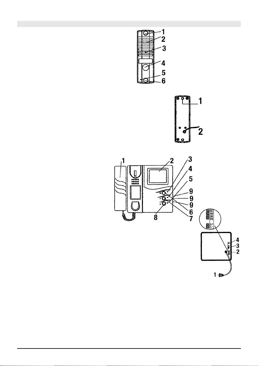
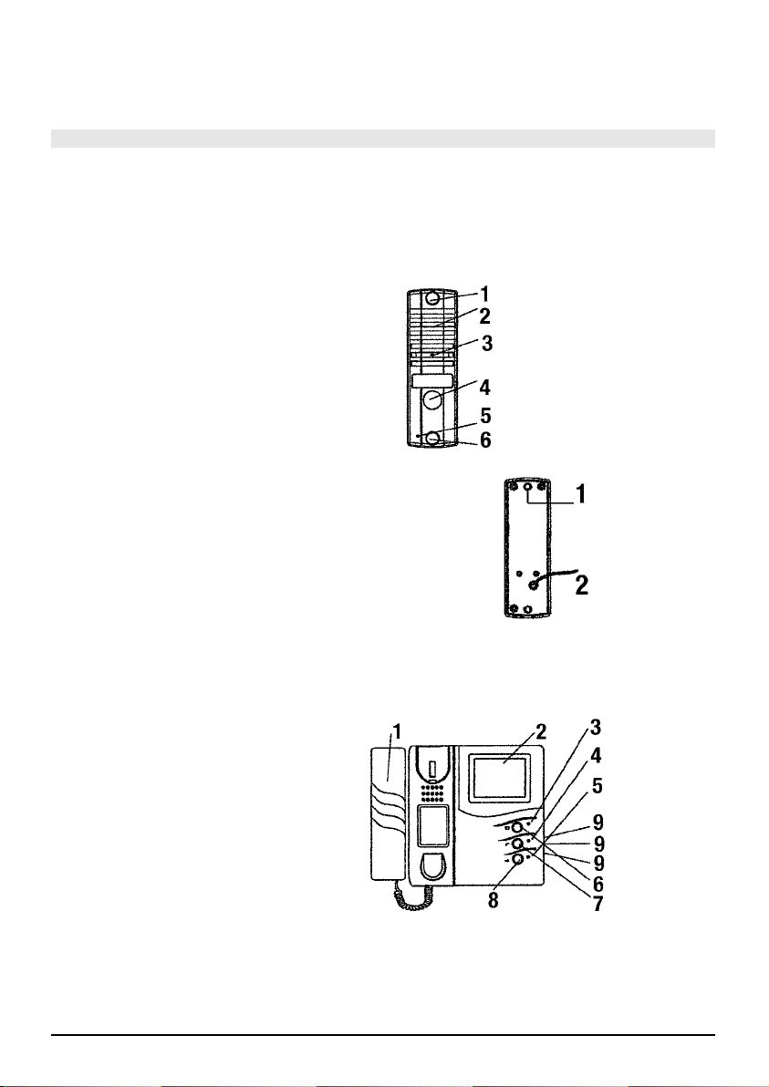
Figure 1 Doorbell camera, front
1. Screw hole
2. Speaker (for the visitor to hear your voice)
3. Camera (for you to see who’s at the door)
4. Button doorbell
5. Microphone
6. Screw hole
Figure 2 Doorbell camera, back
1. Screw hole
2. Cable to transfer picture and sound to the monitor
Figure 3 Monitor, front
1. Receiver
2. Screen
3. Operation LED
4. Intercom LED
5. Door open LED
6. Monitor button
7. Intercom button
(to communicate between different
monitors, if applicable)
8. Door open button
9. On the side: sliders/wheels to set
volume, brightness and contrast
Figure 4 Monitor, back
1. Power cable
2. Connectors for camera cable
3. On-Off switch (used in case of multiple monitors)
4. 75 Ohm switch
Step 1 Mounting the doorbell camera to the frame
• Drill a hole (15 mm) through the frame, at the height you want to mount the
doorbell camera.
• First push the wall bracket, then the sun hood and lastly the camera together. Do not
forget to feed the camera cable through the hole in the wall bracket as well.
• Feed the cable through the hole in the frame and mount the doorbell camera on the
frame with the screw included.
4 © MARMITEK
Figure 1
Figure 2
Figure 3
Figure 4
Page 5
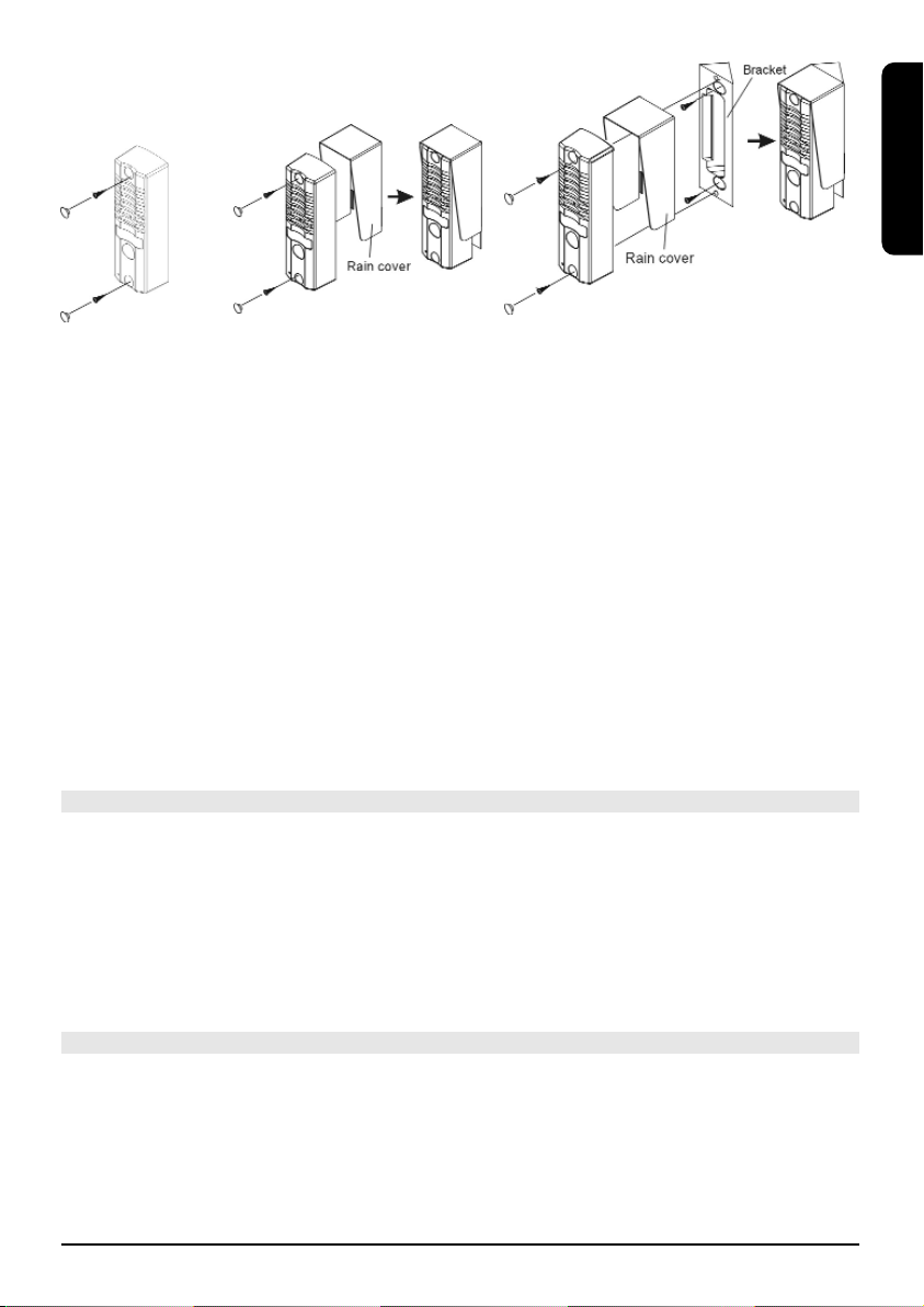
Step 2 Connecting the cables
• The cable included has a connector on one end. Click the doorbell camera connector
onto the connector of the cable included. Lead the cable to the place where you want to
place the monitor. (Attention: you do need a wall socket). If necessary, cut the cable to length.
• Connect the cable to the wall plate. Make sure to connect the cables as follows (fig.4):
• Screw the brown wire into R1 (Video)
• Screw the black wire into R2 (Ground)
• Screw the white wire into R3 (Audio)
• Screw the red wire into R4 (Power)
• Mount the wall plate onto the wall, using the four screws included.
Step 3 Mounting the monitor
• Pick up the monitor and click the connectors of the wall plate into the
back of the monitor.
• Place the monitor against the wall plate and move it down in such a
way that it slides over the wall plate and clicks into place.
• You can always remove the monitor by sliding it up.
Your DoorGuard 100 has now been installed successfully and is ready for use.
5. Using your DoorGuard 100
• The visitor will ring the doorbell.
• The monitor will automatically switch on. You can see who’s at the door and decide to
respond or not.
• To talk to the visitor, pick up the receiver.
• To open the door (only if you have also fitted an electric lock), press the Door open
button.
• Intercom function: (only if you have connected several monitors) you can communicate
to other monitors. Press the Intercom button to use this function.
6. Optional possibilities with your DoorGuard100
Electrical lock for opening the door from the monitor
Needed is an electrical door lock with own supply.
The door-open contact of the monitor is a potential free make contact.
Maximal load of this contact is:DC24V/1A or AC24V/1A
Purchase a suitable electrical door opener from your trade supplier.
You connect the door opener to the L+ and L- contact of the wall plate.
5DOORGUARD 100
TM
ENGLISH
Page 6

Connecting of more monitors
you can connect as much as 4 monitors (obtainable separately: art.nr. 09692 (E-version)
09693 (UK version). Mutually the monitors work as an intercom as well.
N.B.: only the last monitor you connect must be switched on 75 Ohm.
The following monitors should be connected parallel to the wall plate.
So you connect R1, R2 , R3 and R4 with R1, R2, R3 and R4 of the second monitor (see
drawing figure 4). Till a cable length of 25 metres a 4-wire cable of minimal 4 x 0.55 mm
2
can be used. For a cable, long 25 – 50 metres must be used a 75 Ohm coax cable of minimal
0.5 mm
2
(R1 and R2) for the video signal.
When using a cable length of 50 till 100 metres use a 75 Ohm coax cable of minimal 1.0 mm
2
When using a cable length of 100 till 300 meters use a 75 Ohm coax cable of minimal 1.5 mm2.
For the audio signal is no coax cable needed and will a 2 wire cable do (R3 and R4)
7. Optional accessories
Separate Marmitek DoorGuard100 monitor
DGM100 art. no 09692 (E version) 09693 (UK version)
8. FAQ
I don’t get a picture.
Check whether the power cable has been plugged into the wall socket properly.
Check whether the contrast is set to max or min and then turn the wheel on the side of
the monitor for a better picture.
Check whether the receiver is placed on the monitor correctly.
Check whether all cables are connected properly (see the connection diagram for step 2).
I don’t get any sound.
Check whether the wire of the receiver is clicked into the monitor correctly. Remove the
wire and click it in again to make sure.
Check whether all cables are connected properly (see the connection diagram for step 2).
The picture is very fuzzy (white noise).
Check whether the system is suffering from interference, e.g. from power lines,
electrical equipment).
6 © MARMITEK
Page 7

9. Technical data
Monitor :
Resolution monitor: 380 picture lines
Supply: 100 – 240 V AC
Screen: 4’’ black/white
Bell sound: Ding-dong (adjustable volume)
Power consumption: Max 25 watt
Dimensions monitor: 215x205x55mm
Camera:
Resolution: 352 x 288 pixels black/white
Camera: 1/3’’ CMOS
Lens and angle: F 3.6 mm 78
Light sensibility: 0.1 LUX
Night vision: 4 infra red LEDs
Sound: Built in microphone and speaker
Material: Shock resistant metal housing
Dimensions camera: 128x29.5x40mm
Optional connectable : electrical door lock.
Technical specifications door lock: 24V 1A Max. with separate power supply.
7DOORGUARD 100
TM
ENGLISH
ENGLISH
Environmental Information for Customers in the European Union
European Directive 2002/96/EC requires that the equipment bearing this symbol on the product and/or its
packaging must not be disposed of with unsorted municipal waste. The symbol indicates that this product
should be disposed of separately from regular household waste streams. It is your responsibility to dispose
of this and other electric and electronic equipment via designated collection facilities appointed by the gov-
ernment or local authorities. Correct disposal and recycling will help prevent potential negative consequences
to the environment and human health. For more detailed information about the disposal of your old equipment,
please contact your local authorities, waste disposal service, or the shop where you purchased the product.
Page 8

8 © MARMITEK
Page 9

SICHERHEITSHINWEISE
• Um Kurzschluss vorzubeugen, dieses Produkt bitte ausschließlich innerhalb des Hauses und
nur in trockenen Räumen nutzen. Setzen Sie die Komponenten nicht Regen oder
Feuchtigkeit aus. Nicht neben oder nahe eines Bades,Schwimmbades usw. verwenden.
• Setzen Sie die Komponente Ihres Systems nicht extrem hohen Temperaturen oder starken
Lichtquellen aus.
• Das Produkt niemals öffnen: Das Gerät enthält Bestandteile mit lebensgefährlicher
Stromspannung. Überlassen Sie Reparaturen oder Wartung nur Fachleuten.
• Bei einer zweckwidrigen Verwendung, selbst angebrachten Veränderungen oder selbst
ausgeführten Reparaturen verfallen alle Garantiebestimmungen. Marmitek übernimmt bei
einer falschen Verwendung des Produkts oder bei einer anderen Verwendung des Produktes
als für den vorgesehenen Zweck keinerlei Produkthaftung. Marmitek übernimmt für
Folgeschäden keine andere Haftung als die gesetzliche Produkthaftung.
• Dieses Produkt ist kein Spielzeug. Außer Reichweite von Kindern halten.
• Netzadapter: Schließen Sie den Netzadapter erst dann an das Stromnetz an, nachdem Sie
überprüft haben, ob die Netzspannung mit dem auf dem Typenschild angegeben Wert
übereinstimmt. Schließen Sie niemals einen Netzadapter oder ein Netzkabel niemals an,
wenn diese beschädigt sind. In diesem Fall nehmen Sie Kontakt mit Ihrem Lieferanten auf.
1. Einführung
Herzlichen Glückwunsch zum Erwerb vom Marmitek DoorGuard 100. Mit diesem VideoTürtelefon können Sie jederzeit (auch unbemerkt) zunächst einmal schauen und hören, wer
an Ihrer Tür steht, bevor Sie sich entschließen die Tür zu öffnen. Die Kamera ist in der
schmalen Türklingel angebracht und gibt eine gute Bildqualität, sogar im Dunkeln. Die
Türkamera kann durch seine Schmalheit problemlos am Türrahmen montiert werden. Sie
brauchen also keine Löcher in (zweischalige) Wände an zu bringen.
2. Verpackungsinhalt
• 1 Monitor mit Bildschirm
• 1 Wandplatte für den Monitor
• 1 Türklingel mit Kamera
• 1 Wandhalter
• 1 Sonnen- und Regenschutz
• 10 Meter 4-adriges Verlängerungskabel
• verschiedene Befestigungs- und Schraubmaterialien
• diese Gebrauchsanleitung
3. Wie funktioniert es?
Ein Besucher klingelt (mit der Klingel der Türkamera) und Sie hören einen Ding-Dongton. Bild
und Ton des Besuchers werden direkt auf dem Monitor wiedergegeben. Wenn Sie mit dem
Besucher kommunizieren möchten, dann können Sie den Hörer abnehmen und mit Ihrem
Besucher reden. Wenn Sie ein elektrisches Schloss montiert haben (optional im Fachhandel
erhältlich) können Sie die Tür auch fernbedient öffnen.
3.1 Die Montage
Sie bohren in der gewünschten Anbringungshöhe der Türkamera ein Loch in den Türrahmen.
Nun befestigen Sie den Wandhalter mit der darauf montierten schmalen Türkamera mit
Schrauben auf dem Rahmen. Die Wandplatte für den Monitor bringen Sie an einer
bevorzugten Stelle in Ihrem Haus, z.B. im Flur, an. Der Monitor muss in nächster Nähe einer
9DOORGUARD 100
TM
DEUTSCH
Page 10
Steckdose aufgestellt werden. Schließen Sie nun die Türkamera an das Verlängerungskabel an
und dies wiederum an den Monitor. Von nun an können Sie ehe Sie die Tür öffnen sehen wer
vor der Tür steht.
4. An die Arbeit (Installation)
Beschreibung der Einzelteile
Abbildung 1 Vorderseite der Türkamera
1. Schraubenloch
2. Lautsprecher (der Besucher kann mit Ihnen
kommunizieren)
3. Kamera (Sie sehen wer vor der Tür steht)
4. Klingelknopf
5. Mikrofon
6. Schraubenloch
Abbildung 2 Rückseite der Türkamera
1. Schraubenloch
2. Kabel für Versendung von Bild und Ton
zum Monitor
Abbildung 3 Vorderseite des Monitors
1. Hörer
2. Bildschirm
3. In Betrieb LED-Anzeige
4. Sprechanlage LED-Anzeige
5. Türöffner LED-Anzeige
6. Monitorschalter
7. Sprechanlageschalter (gegenseitiger
Verkehr zwischen mehreren
Monitoren, wenn zutreffend)
8. Tür-Öffnungsschalter
9. Seitlich: Schieber/Drehrädchen für
Lautstärke, Bildhelligkeit und Kontrast
10 © MARMITEK
Abbildung 1
Abbildung 2
Abbildung 3
Page 11
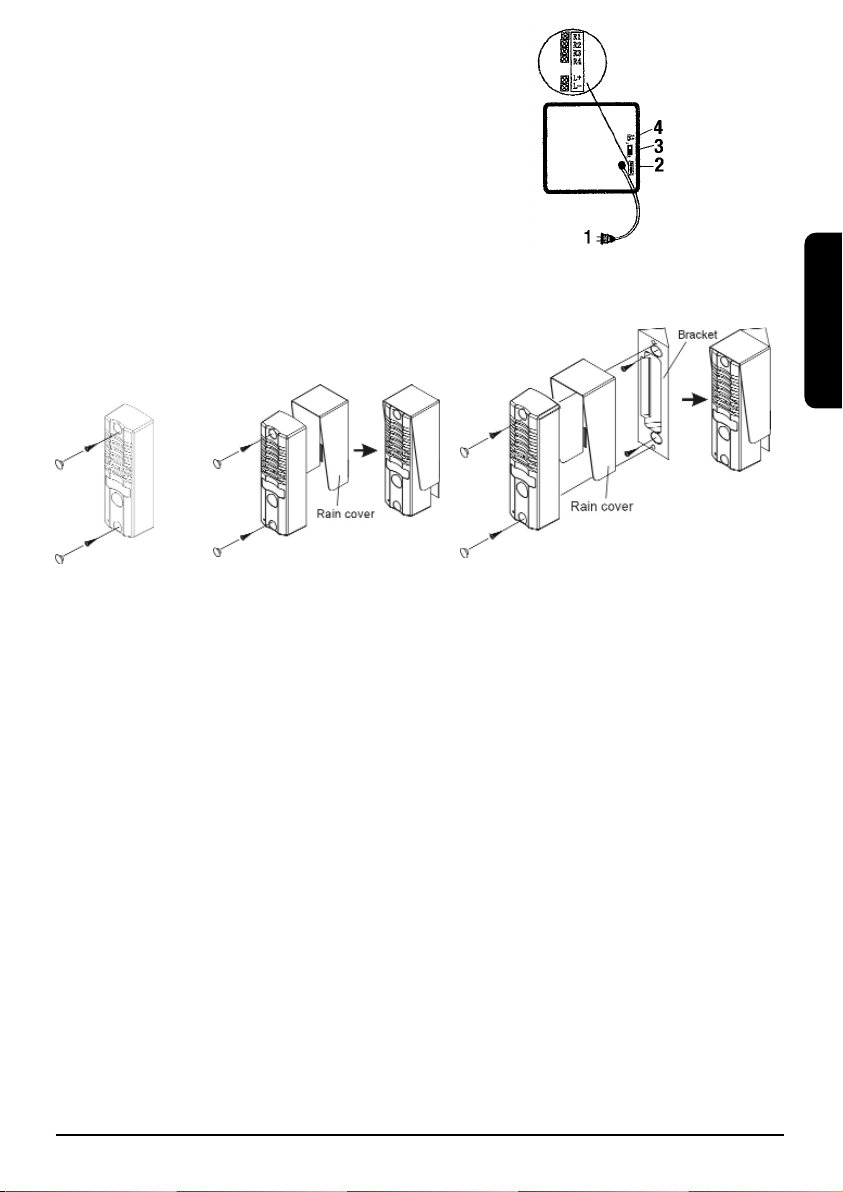
Abbildung 4 Rückseite des Monitors
1. Kabel für Netzspeisung
2. Anschlussverbindungen für das Kamerakabel
3. EIN/AUS Schalter (bei Betrieb von mehreren Monitoren)
4. 75 Ohm Schalter
Schritt 1 Türrahmenmontage der Türkamera.
• Bohren Sie in der gewünschten Anbringungshöhe der
Türkamera ein 15 mm Loch durch den Türrahmen
• Bringen Sie zunächst den Wandhalter, dann den Sonnen/Regenschutz und zuletzt die
Kamera an. Vergessen Sie nicht, auch das Kabel der Kamera durch das
Wandhalterungsloch zu leiten.
• Schieben Sie nun das Kabel durch das Bohrloch
und montieren Sie das Ganze mit den
mitgelieferten Schrauben an den Türrahmen.
Schritt 2 Das Anschließen der Kabel
• Das mitgelieferte Kabel hat an einem Ende ein Verbindungsstück. Klicken Sie das
Verbindungsstück der Türkamera an das des mitgelieferten Kabels. Führen Sie das Kabel zur
Wandmontagestelle des Monitors. (Achtung: in der Nähe muss sich eine Steckdose befinden).
Verkürzen Sie das Kabel im Bedarfsfall.
• Schließen Sie das Kabel an die Wandplatte an. Beachten Sie das Anschlussschema (Abb.4):
• Schrauben Sie das braune Kabel in R1 (Video)
• Schrauben Sie das schwarze Kabel in R2 (Ground)
• Schrauben Sie das weiße Kabel in R3 (Audio)
• Schrauben Sie das rote Kabel in R4 (Speiseleitung)
• Montieren Sie die Wandplatte mit den vier Schrauben an eine Wand.
Schritt 3 Den Monitor an die Wand montieren
• Nehmen Sie den Monitor auf und klicken Sie die Verbindungsstücke
der Wandplatte in de Rückseite des Monitors
• Halten Sie nun den Monitor gegen die Wandplatte und schieben ihn
so (von oben nach unten), dass der Monitor die Wandplatte
heruntergleitet und mit einem Klick einrastet.
• Sie können den Monitor jederzeit wieder entfernen indem Sie ihn wieder hochschieben.
Ihr DoorGuard 100 ist nun installiert und gebrauchsfertig.
11DOORGUARD 100
TM
DEUTSCH
Abbildung 4
Page 12

5. Verwendung des DoorGuard 100
• Ein Besucher drückt auf die Türkameraklingel.
• Der Bildschirm Ihres Monitors schaltet sich automatisch ein. Sie können nun sehen wer
vor der Tür steht und entscheiden ob Sie die Tür öffnen möchten.
• Nehmen Sie um mit dem Besucher zu reden, den Hörer vom Monitor.
• Drücken Sie um die Tür zu öffnen (nur möglich wenn ein elektrisches Schlosses montiert
worden ist): auf den Tür-Öffnungsschalter.
• Sprechanlagefunktion: (nur möglich, wenn Sie mehrere Monitore angeschlossen habe)
Sie können über mehrere Monitore miteinander reden. Drücken Sie hierzu auf den
Sprechanlageschalter.
6. Optionale Möglichkeiten mit Ihrer DoorGuard100
Elektrisches Schloss zum Öffnen der Tür vom Monitor aus.
Benötigt wird ein elektrisches Türschloss mit eigener Speisung.
Der Türöffnungskontakt des Monitors ist ein potenzialfreier Verbindungskontakt.
Die Höchstbelastung dieses Kontaktes beträgt: DC24V/1A oder AC24V/1A.
Ein passender, elektrischer Türöffner ist bei Ihrem Fachhändler erhältlich.
Schließen Sie den Türöffner an den L+ und L- Kontakt einer Wandplatte an.
Mehrere Monitore anschließen
Sie können bis zu 4 Monitore anschließen (einzeln erhältlich: Art.-Nr.: 09692 (E Ausführung)
09693 (UK Ausführung).
Die Monitore können untereinander auch als Wechselsprechanlage genutzt werden.
Achtung: nur der zuletzt angeschlossene Monitor muss auf 75 Ohm geschaltet werden.
Nachfolgende Monitore schließen Sie parallel an die Wandplatte an.
Sie verbinden also R1, R2, R3 und R4 mit R1, R2, R3 und R4 des zweiten Monitors
(sehen Sie Abb.4).
Für eine Kabellänge von bis zu 25 Meter können Sie ein 4-adriges Kabel von mindestens
4x 0,55mm
2
verwenden.
Für eine Kabellänge von 25~50 Meter müssen Sie für das Videosignal mindestens ein
Koaxialkabel, 75 Ohm von 0,5 mm
2
verwenden (R1 und R2).
Verwenden Sie für eine Kabellänge von 50 bis 100 Meter ein 75 Ohm Koaxialkabel von
mindestens 1.0mm
2
.
Verwenden Sie für eine Kabellänge von 100 bis 300 Meter ein 75 Ohm Koaxialkabel von
mindestens 1.5mm
2
.
Für das Audiosignal wird kein Koaxialkabel benötigt. Hier genügt ein 2-adriges Kabel.
(R3 und R4).
7. Zusätzlich erhältlich
Einzelner Marmitek Monitor DoorGuard100
DGM100 Art.-Nr. 09692 (E version) 09693 (UK version)
8. Problemlösungen
Ich bekomme kein Bild
Überprüfen Sie, ob das Speisungskabel gut in der Steckdose steckt
Überprüfen Sie, ob der Kontrast auf Maximal oder Minimal einstellt ist und drehen Sie
an dem sich an der Seite befindenden Rächen zur Einstellung des Bildes
Kontrollieren Sie, ob der Telefonhörer gut aufgelegt ist.
Überprüfen Sie, ob die Kabel richtig angeschlossen sind (siehe Anschlussschema Schritt 2)
12 © MARMITEK
Page 13

Ich empfange keinen Ton
Kontrollieren Sie, ob das Telefonkabel richtig an den Monitor angeschlossen ist.
Lösen Sie eventuell das Kabel und schließen es wieder an.
Überprüfen Sie, ob die Kabel richtig angeschlossen sind (Siehe Anschlussschema Schritt 2)
Das Bild ist verschwommen (schneit)
Kontrollieren Sie auf Überlagerung. Zum Beispiel durch ein Hochspannungskabel,
elektrische Geräte usw.).
9. Technischen Daten
MONITOR:
Auflösung Monitor: 380 Rasterzeilen
Speisung: 100-240V AC
Bildschirm: 4" schwarz/weiß
Klingelton: Ding-Dong (Lautstärke einstellbar)
Stromverbrauch: Max. 25 Watt
Abmessungen Monitor: 215x205x55mm
KAMERA:
Auflösung: 352x288 Pixel (schwarz/weiß)
Kamera: 1/3" CMOS
Objektiv und Winkel: F3.6 mm 78°
Lichtempfindlichkeit: 0.1 LUX
Nachtsicht: 4 Infrarot LED
Ton: Eingebautes Mikrofon und Lautsprecher
Material: Schlagfestes Metallgehäuse
Abmessungen Kamera: 128x29,5x40mm
Optional anschließbar: elektrisches Türschloss.
Technische Daten Türschloss: 24V 1A max. mit eigener Stromversorgung.
13DOORGUARD 100
TM
DEUTSCH
Umweltinformation für Kunden innerhalb der Europäischen Union
Die Europäische Richtlinie 2002/96/EC verlangt, dass technische Ausrüstung, die direkt am Gerät und/oder
an der Verpackung mit diesem Symbol versehen ist nicht zusammen mit unsortiertem Gemeindeabfall
entsorgt werden darf. Das Symbol weist darauf hin, dass das Produkt von regulärem Haushaltmüll getrennt
entsorgt werden sollte. Es liegt in Ihrer Verantwortung, dieses Gerät und andere elektrische und elektronis-
che Geräte über die dafür zuständigen und von der Regierung oder örtlichen Behörden dazu bestimmten
Sammelstellen zu entsorgen. Ordnungsgemäßes Entsorgen und Recyceln trägt dazu bei, potentielle negative Folgen
für Umwelt und die menschliche Gesundheit zu vermeiden. Wenn Sie weitere Informationen zur Entsorgung Ihrer
Altgeräte benötigen, wenden Sie sich bitte an die örtlichen Behörden oder städtischen Entsorgungsdienste oder an
den Händler, bei dem Sie das Produkt erworben haben.
Page 14

14 © MARMITEK
Page 15

AVERTISSEMENTS DE SECURITE
• Afin d'éviter un court-circuit, ce produit ne doit être utilisé qu'à l'intérieur, et uniquement
dans des endroits secs. Ne pas exposer les composants à la pluie ou à l'humidité. Ne pas
utiliser à côté de ou près d'une baignoire, une piscine, etc.
• Ne pas exposer les composants de votre système à des températures extrêmement élevées
ou à des sources de lumières trop fortes.
• Ne jamais ouvrir le produit: l'appareil contient des éléments qui sont sous tension très
dangereuse. Les réparations ou l'entretien ne doivent être effectués que par des personnes
compétentes.
• Toute utilisation impropre, toute modification ou réparation effectuée vous-même annule la
garantie. Marmitek n’accepte aucune responsabilité dans le cas d’une utilisation impropre
du produit ou d’une utilisation autre que celle pour laquelle le produit est destiné. Marmitek
n’accepte aucune responsabilité pour dommage conséquent, autre que la responsabilité
civile du fait des produits.
• Ce produit n’est pas un jouet et doit être rangé hors de la portée des enfants.
• Adaptateur: Brancher l’adaptateur secteur sur le réseau électrique seulement après avoir
vérifié que la tension d’alimentation correspond à la valeur indiquée sur les plaques
d’identification. Ne jamais brancher un adaptateur secteur ou un cordon d’alimentation
lorsque celui-ci est endommagé. Dans ce cas, veuillez contacter votre fournisseur.
1. Introduction
Félicitations pour l’achat du Marmitek Doorguard 100. Par l’intermédiaire de ce portier vidéo,
vous êtes à même (éventuellement de manière anonyme) de voir et d’écouter au préalable la
personne qui se trouve devant votre porte, avant de décider d’ouvrir. La caméra est dissimulée
dans l’étroite sonnette de porte et fournit une bonne qualité d’image, même s’il fait noir. La
petite sonnette de porte avec caméra intégrée est suffisamment étroite pour son montage au
chambranle. Il n’est donc pas nécessaire de percer des trous dans les murs (creux).
2. Contenu de l’emballage
• 1 moniteur avec écran
• 1 plaque murale pour le moniteur
• 1 sonnette de porte avec caméra intégrée
• 1 support mural
• 1 abat-vent/pare soleil
• Rallonge à 4 conducteurs de 10 mètres
• Divers matériaux de fixation et fixations à vis
• Ce manuel
3. Comment cela fonctionne-t-il ?
Le visiteur sonne (au moyen de la sonnette où est intégrée la caméra). Vous entendez un
ding-dong. L’image et le son du visiteur sont directement visibles sur le moniteur. Lorsque
vous souhaitez communiquer avec le visiteur, vous pouvez décrocher le récepteur et lui parler.
Lorsque vous avez monté une serrure électrique (disponible en option), vous êtes également à
même d’ouvrir la porte à distance.
15DOORGUARD 100
TM
FRANÇAIS
Page 16

3.1 Comment faut-il le monter ?
Vous percez un trou dans le chambranle, au niveau de l’endroit où vous voulez monter la
sonnette à caméra intégrée. Fixez l’étroite sonnette à caméra intégrée sur le support mural,
puis fixez le tout au chambranle au moyen de petites vis. Fixez le moniteur au moyen de la
plaque murale quelque part dans la maison, par exemple dans le couloir. Vous devez placer le
moniteur en tout cas à proximité d’une prise murale. Branchez le petit câble de la sonnette à
caméra intégrée sur la rallonge et branchez celle-ci à son tour sur le moniteur. Vous pouvez
maintenant voir le visiteur avant d’ouvrir.
4. L’installation
Description des pièces
Illustration 1 Côté face de la sonnette
à caméra intégrée
1. Logement de vis
2. Haut-parleur (permet au visiteur d’entendre
votre voix)
3. Caméra (vous permet de voir le visiteur
devant la porte)
4. Touche sonnette
5. Microphone
6. Logement de vis
Illustration 2 Côté arrière de la sonnette à caméra intégrée
1. Logement de vis
2. Câble pour l’envoi de l’image et du son au moniteur)
Illustration 3 : Côté face du moniteur
1. Récepteur
2. Ecran
3. Voyant DEL en service
4. Voyant DEL interphone
5. Voyant DEL gâche électrique
6. Touche moniteur
7. Touche interphone (pour la commu-
nication entre plusieurs moniteurs,
si applicable)
8. Touche gâche électrique
9. Sur le côté : régulateurs coulissants/
roulettes pour volume, luminosité et contraste.
16 © MARMITEK
Illustration 1
Illustration 2
Illustration 3
Page 17

Illustration 4 Côté arrière du moniteur
1. Cordon pour alimentation par secteur
2. Connecteurs de raccordement pour câble de caméra
3. Interrupteur marche/ arrêt (utilisable pour plusieurs moniteurs)
4. Interrupteur 75 Ohm
Etape 1 Montage de la sonnette à caméra intégrée au chambranle
• Percez un trou (15 mm) à travers le chambranle, au niveau de
l’endroit où vous voulez accrocher la sonnette à caméra intégrée.
• Assemblez d’abord le support mural, puis le pare-soleil, puis la caméra. N’oubliez pas de
faire passer le câble de la caméra également à travers le trou dans le support mural.
• A présent, faites glisser le câble à travers le trou dans le chambranle et fixez le tout au
chambranle à l’aide des vis fournies.
Etape 2 Branchement des câbles
• L’un des bouts du câble fourni est doté d’un connecteur. Accrochez jusqu’à enclenchement
le connecteur de la sonnette à caméra intégrée au connecteur du câble fournie. Menez le
câble à l’endroit où le moniteur sera accroché (faites attention à ce qu’une prise murale soit
à proximité). Coupez le câble à la mesure, si besoin est.
• Branchez le câble sur la plaque murale. Respectez le schéma de connexion (illustration 4) :
• Vissez le fil brun sur R1 (Vidéo)
• Vissez le fil noir sur R2 (Terre)
• Vissez le fil blanc sur R3 (Audio)
• Vissez le fil rouge sur R4 (Tension d’alimentation)
• Fixez la plaque murale au mur au moyen des quatre vis.
Etape 3 Montage du moniteur au mur
• Prenez le moniteur et accrochez les connecteurs de la plaque murale
à l’arrière du moniteur, jusqu’à enclenchement (voir illustration 7)
• Posez alors le moniteur contre la plaque murale et faites le glisser de
telle façon (du haut vers le bas) que le moniteur glisse sur la plaque
murale et s’y accroche avec un déclic.
• Vous pouvez décrocher le moniteur à tout moment, en le faisant glisser
vers le haut.
A présent, votre Doorguard 100 a été installé avec succès et est prêt pour utilisation.
17DOORGUARD 100
TM
FRANÇAIS
Illustration 4
Page 18

5. Utilisation de votre Doorguard 100
• Le visiteur sonne au moyen de la sonnette à caméra intégrée.
• L’écran du moniteur s’allume automatiquement. Vous voyez qui a sonné, puis vous
pouvez décider de réagir ou non.
• Pour parler au visiteur : décrochez le récepteur du moniteur
• Pour ouvrir la porte (uniquement possible lorsque vous avez monté une serrure
électrique) : appuyez sur la touche d’ouverture de la porte d’entrée.
• Fonction d’interphone :(uniquement possible lorsque vous avez branché plusieurs
moniteurs) vous pouvez vous parlez par l’intermédiaire de plusieurs moniteurs.
Appuyez pour cela sur la touche Interphone.
6. Options disponibles avec votre DoorGuard100
Fermeture électrique préalable à l’ouverture de la porte via le moniteur.
Il est indispensable de disposer d’un ferme-porte électrique muni de sa propre alimentation.
Le contact d’ouverture de porte du moniteur est un contact à fermeture libre de potentiel.
La charge maximale de ce contact est de 24 V/1 A (CC) ou 24 V/1 A (AC).
Procurez-vous un ouvre-porte électrique auprès de votre revendeur spécialisé.
Branchez l’ouvre-porte aux bornes L+ et L- de la plaque murale.
Branchement de plusieurs moniteurs.
Vous pouvez brancher jusqu’à 4 moniteurs [disponibles séparément : articles n° 09692
(version E) et 09693 (version UK)].
Ce moniteurs fonctionnent également réciproquement comme interphones.
Attention : seul le dernier moniteur branché doit être connecté sur 75 Ohm.
Branchez les autres moniteurs en circuit parallèle sur la plaque murale.
Vous devez donc connecter R1, R2, R3 et R4 avec R1, R2, R3 et R4 du deuxième moniteur.
(Reportez-vous à l’illustration 4).
Il est possible d’utiliser un câble à 4 conducteurs d’au moins 4 x 0,55 mm
2
sur une longueur
maximale de 25 mètres.
Pour une longueur de câble entre 25 et 50 mètres, il est nécessaire d’utiliser au minimum un
câble coaxial 75 ohms de 0,5 mm
2
(R1 et R2) pour le signal vidéo.
Pour une longueur de câble entre 50 et 100 mètres, utilisez un câble coaxial 75 ohms d’au
moins 1,0 mm
2
.
Pour une longueur de câble entre 100 et 300 mètres, utilisez un câble coaxial 75 ohms d’au
moins 1,5 mm
2
.
Le signal audio ne nécessite pas de câble coaxial. Un câble à 2 conducteurs est en outre
suffisant (R3 et R4).
7. Disponible en option
Marmitek moniteur séparé DoorGuard 100
DGM 100 no. d’art. 09692 (E version) 09693 (UK version)
18 © MARMITEK
Page 19

8. Résolution des problèmes
Il n’y a pas d’image
Vérifiez que le câble d’alimentation est correctement branché sur la prise.
Vérifiez que le contraste est mis sur maximum ou minimum et tournez la roulette située
sur le côté pour une meilleure image
Vérifiez que le récepteur est correctement accroché au moniteur
Vérifiez que les câbles sont correctement branchés (voir schéma de connexion à l’étape 2)
Il n’y a pas de son
Vérifiez que le fil du récepteur est accroché au moniteur jusqu’à enclenchement.
Décrochez et raccrochez-le pour être sûr.
Vérifiez que les câbles sont correctement branchés (voir schéma de connexion à l’étape 2)
L’image est floue (neige)
Vérifiez la présence d’interférence à proximité. Par exemple un câble haute tension,
appareils électrique, etc.)
9. Caractéristiques techniques :
MONITEUR :
Résolution : 380 lignes
Alimentation : 100 - 240 V CA
Écran : 4" noir et blanc
Sonnerie : Ding-dong (volume réglable)
Consommation : 25 Watt maxi
Dimensions du moniteur : 215x205x55mm
CAMÉRA :
Résolution : 352 x 288 pixels (noir et blanc)
Caméra : 1/3" CMOS
Objectif et angle : F 3,6 mm 78°
Sensibilité lumineuse : 0,1 LUX
Vision de nuit : 4 DEL infrarouges
Son : Microphone et haut-parleur intégrés
Matériau : Boîtier métallique incassable
Dimensions de la caméra : 128x29,5x40mm
Matériel compatible en option : ferme-porte électrique.
Caractéristiques techniques serrure : 24V 1A Max avec sa propre alimentation.
19DOORGUARD 100
TM
FRANÇAIS
Informations environnementales pour les clients de l’Union européenne
La directive européenne 2002/96/CE exige que l’équipement sur lequel est apposé ce symbole sur le produit et/ou son emballage ne soit pas jeté avec les autres ordures ménagères. Ce symbole indique que le produit doit être éliminé dans un circuit distinct de celui pour les déchets des ménages. Il est de votre responsabilité de jeter ce matériel ainsi que tout autre matériel électrique ou électronique par les moyens de col-
lecte indiqués par le gouvernement et les pouvoirs publics des collectivités territoriales. L’élimination et le
recyclage en bonne et due forme ont pour but de lutter contre l’impact néfaste potentiel de ce type de produits sur
l’environnement et la santé publique. Pour plus d’informations sur le mode d’élimination de votre ancien équipement, veuillez prendre contact avec les pouvoirs publics locaux, le service de traitement des déchets, ou l’endroit où
vous avez acheté le produit.
Page 20

20 © MARMITEK
Page 21

21DOORGUARD 100
TM
ESPAGNOL
AVISOS DE SEGURIDAD
• Para evitar un cortocircuito, este producto solamente se usa en casa y en habitaciones
secas. No exponga los componentes del sistema a la lluvia o a la humedad. No se use cerca
de una bañera, una piscina, etc.
• No exponga los componentes del sistema a temperaturas extremamente altas o a focos de
luz fuertes.
• Nunca abra el producto: el equipo contiene piezas con un voltaje mortal. Deja las
reparaciones o servicios a personal experto.
• En caso de uso indebido o modificaciones y reparaciones montados por su mismo, la
garantía se caducará. En caso de uso indebido o impropio, Marmitek no asume ninguna
responsabilidad para el producto. Marmitek no asume ninguna responsabilidad para daños
que resultan del uso impropio, excepto según la responsabilidad para el producto que es
determinada por la ley.
• Este producto no es un juguete. Asegúrese de que está fuera del alcance de los niños.
• Adaptador de red: No conecte el adaptador de red a la red de alumbrado antes de que
haya controlado si la tensión de red corresponde con el valor indicado en la estampa de
tipo. Nunca conecte un adaptador de red o un cable a la red si ése está dañado. En este
caso, por favor entre en contacto con su proveedor.
1. Introducción
Le felicitamos por su compra de DoorGuard100™ de Marmitek. Con este portero automático con
video puede ver y oír primero (eventualmente de forma anónima) quien llama a la puerta antes de
que usted decida abrirla. La cámara se encuentra ocultada en el timbre de la puerta y produce
imagen de buena calidad, incluso en la oscuridad. La cámara del timbre es lo suficientemente
pequeña como para montarla en el marco de la puerta. No necesita hacer agujeros en la pared.
2. Contenido de la caja
• 1 monitor con pantalla
• 1 placa de soporte
• 1 timbre de puerta con cámara
• 1 aro de soporte
• 1 capucha para el sol / lluvia
• un cable alargador de 10 metros con 4 conductores
• materiales para atornillar y fijar
• este manual
3. ¿Cómo funciona?
El visitante llama a la puerta (con el timbre que contiene la cámara). Usted oye un timbre. La
imagen y el sonido del visitante se pueden ver inmediatamente en el monitor. Si usted se
quiere comunicar con el visitante, puede descolgar el auricular y hablar con su visitante. Si
usted ha instalado una cerradura eléctrica (se puede adquirir de forma opcional en una tienda
especializada), entonces usted también puede abrir la puerta a distancia.
3.1. ¿Cómo lo puede montar?
Usted taladra un agujero en el marco de la puerta, a la altura donde usted quiere colocar el
timbre con la cámara. Usted fija a la pared con los tornillos el aro con la cámara del timbre
montada sobre él. Usted instala el monitor en la placa de soporte en un lugar de su casa, por
ejemplo en el pasillo. Usted tiene que colocar el monitor en las cercanías de un enchufe.
Conecta el cable de la cámara del timbre al cable alargador y conecta éste a su vez al monitor. Desde ahora usted puede ver primero quien llama a su puerta antes de que usted la abra.
Page 22

22 © MARMITEK
4. Instalación
Descripción de los componentes
Figura 1 Parte delantera de la cámara del timbre
1. Agujero para tornillo
2. Altavoz (el visitante le puede oír)
3. Cámara (usted ve quien llama a la puerta)
4. Botón del timbre
5. Micrófono
6. Agujero para tornillo
Figura 2 Parte trasera de la cámara del timbre
1. Agujero para tornillo
2. Cable para mandar imagen y sonido al monitor
Figura 3 Parte delantera del monitor
1. Auricular
2. Pantalla
3. LED en funcionamiento
4. LED del interfono
5. LED del dispositivo de apertura de
la puerta
6. Botón del monitor
7. Botón del interfono (para la
comunicación entre varios
monitores, si procede)
8. Botón para abrir la puerta
9. En el lateral: rueditas para el volu-
men, claridad y contraste.
Figura 4 Parte trasera del monitor
1. 1. Cable para la alimentación
2. Conectores para el cable de la cámara
3. Interruptor (para la utilización de más monitores)
4. Interruptor de 75 Ohm
Paso 1 Montaje de la cámara del timbre en el marco de la puerta
• Taladre un agujero (15 mm.) en el marco, a la altura donde usted quiera colocar la
cámara.
• Deslice primero el aro, después la capucha y luego la cámara. No se olvide de guiar el
cable de la cámara través del agujero al aro.
• Deslice el cable a través del agujero en el marco de la puerta y fije el conjunto al marco
con los tornillos incluidos en la caja.
Figure 1
Figure 2
Figure 3
Figure 4
Page 23

23DOORGUARD 100
TM
Paso 2 Conexión de los cables
• El cable incluido tiene un conector en uno de los extremos. Haga clic con el conector de la
cámara del timbre en el conector del cable incluido. Guíe el cable hasta el lugar donde colgará
el monitor. (Atención: es necesario que haya un enchufe cerca). Acorte el cable si es necesario.
• Conecte el cable a la placa de soporte. Preste atención al esquema de conexión (figure 4):
• Atornille el cable marrón al R1 (Video).
• Atornille el cable negro al R2 (Tierra).
• Atornille el cable blanco al R3 (Sonido).
• Atornille el cable rojo al R4 (Tensión de fuente de alimentación).
• Posicione la placa de soporte en la pared con los cuatro tornillos.
Paso 3 Montaje del monitor en la pared
• Coja el monitor y haga clic con los conectores de la placa de soporte
en la parte trasera del monitor.
• Posicione el monitor contra la pared y muévalo de tal forma (de
arriba abajo) que el monitor se deslice sobre la placa de soporte y
se quede fijo con un clic.
• Usted puede soltar el monitor en cualquier momento deslizándolo
hacia arriba.
Usted ha instalado su DoorGuard100 con éxito y está listo para ser utilizado.
5. Utilización de su DoorGuard100
• El visitante llama a la puerta con la cámara del timbre.
• La pantalla del monitor se enciende automáticamente. Usted ve quien ha llamado y
puede decidir si quiere contestar o no.
• Para hablar con el visitante: coja el auricular del monitor.
• Para abrir la puerta (sólo es posible si usted ha montado una cerradura eléctrica):
presione en el botón de apertura de puerta.
• Función interfono (sólo es posible si usted ha conectado más monitores): usted puede
hablar con otros a través de otros monitores. Para ello haga clic en el botón del
interfono.
ESPAGNOL
Page 24

24 © MARMITEK
6. Posibilidades opcionales de su DoorGuard100
Cerradura eléctrica para abrir la puerta desde el monitor.
Es necesario una cerradura eléctrica con fuente de alimentación propia.
El contacto del monitor para la apertura de la puerta es un contacto de cierre sin potencial.
La carga máxima de este contacto es: DC24V/1A o AC24V/1A.
Compre un abridor de puerta eléctrico adecuado en un comercio especializado.
Conecte el abridor de puerta a los contactos L+ y L- de la placa de soporte.
Conexión de más monitores
Usted puede conectar hasta 4 monitores (adquiribles por separado: nr. art. 09692 (versión E)
09683 (versión RU).
Los monitores funcionan entre si como interfono.
Atención: sólo el último monitor que conecte tiene que estar conectado en 75 Ohm.
Los demás monitores los conecta en paralelo a la placa de soporte.
Usted conecta R1, R2, R3 y R4 con R1, R2, R3 y R4 del segundo monitor (vea figure 4).
Usted puede utilizar un cable de 4 conductores de 4x0,55mm
2
como mínimo con una longitud de hasta 25 metros.
Para un cable de 25 a 50 metros, utilice como mínimo un cable coaxial, 75 Ohm de 0,5 mm
2
(R1 y R2) para la señal de video.
Para un cable de 50 a 100 metros, utilice un cable coaxial de 75 Ohm, de 1.0 mm
2
como
mínimo.
Para un cable de 100 a 300 metros, utilice un cable coaxial de 75 Ohm, de 1.5 mm
2
como
mínimo.
Para la señal de audio no es necesario utilizar un cable coaxial y un cable de 2 conductores
(R3 y R4) es suficiente.
7. Opción disponible
Monitor suelto DoorGuard 100 de Marmitel.
DGM100 nr. art. 09692 (versión E) 09693 (versión RU).
8. Solución de problemas
No se recibe imagen
Compruebe si el cable de alimentación está bien conectado en el enchufe.
Compruebe si el contraste está al máximo o al mínimo y gire la ruedita en el lateral para
mejorar la imagen.
Compruebe si el auricular cuelga correctamente del monitor.
Compruebe si los cables están conectados correctamente (vea esquema de conexión en el
paso 2).
No se recibe sonido
Compruebe si el cable del auricular está bien conectado en el monitor. Sáquelo y haga clic de
nuevo por si acaso.
Compruebe si los cables están conectados correctamente (vea esquema de conexión en el
paso 2).
La imagen es borrosa (nieve)
Compruebe si hay alguna interferencia cerca. Por ejemplo u cable de alta tensión, aparatos
eléctricos, etc.
Page 25

25DOORGUARD 100
TM
ESPAGNOL
9. Datos técnicos
MONITOR:
Resolución del monitor: 380 líneas de imagen
Alimentación: 100-240 V AC
Pantalla: 4” blanco/negro
Timbre de llamada: Ding-Dong (el volumen es regulable)
Consumo: Máx. 25 Watt
Dimensiones del monitor: 215x205x55 mm
CÁMARA:
Resolución: 352x288 Píxeles (blanco-negro)
Cámara: 1/3” CMOS
Lente y ángulo: F3.6 mm. 78º
Sensibilidad luminosa: 0.1 LUX
Visión nocturna: 4 LED infrarrojos
Sonido: Micrófono y altavoz incorporados
Material: Envoltura de metales a prueba de golpes
Dimensiones de la cámara: 128x29,5x40 mm
Se puede conectar de forma opcional: una cerradura eléctrica.
Especificaciones técnicas de la cerradura: 24V 1A Máx. con alimentación propia.
Información medioambiental para clientes de la Unión Europea
La Directiva 2002/96/CE de la UE exige que los equipos que lleven este símbolo en el propio aparato y/o en
su embalaje no deben eliminarse junto con otros residuos urbanos no seleccionados. El símbolo indica que
el producto en cuestión debe separarse de los residuos domésticos convencionales con vistas a su eliminación. Es responsabilidad suya desechar este y cualesquiera otros aparatos eléctricos y electrónicos a
través de los puntos de recogida que ponen a su disposición el gobierno y las autoridades locales. Al
desechar y reciclar correctamente estos aparatos estará contribuyendo a evitar posibles consecuencias negativas para
el medio ambiente y la salud de las personas. Si desea obtener información más detallada sobre la eliminación segura
de su aparato usado, consulte a las autoridades locales, al servicio de recogida y eliminación de residuos de su zona
o pregunte en la tienda donde adquirió el producto.
Page 26

26 © MARMITEK
Page 27

27DOORGUARD 100
TM
ITALIANO
PRECAUZIONI DI SICUREZZA
• Per evitare il pericolo di cortocircuito utilizzare questo prodotto esclusivamente al coperto e
in luoghi asciutti. Non esporre i componenti di questo prodotto a pioggia o umidità. Non
utilizzare vicino alla vasca da bagno, piscina, ecc.
• Non esporre i componenti del sistema a temperature eccessivamente alte o a fonti intense
di luce.
• Non aprire mai il prodotto: nell’apparecchio ci sono parti che potrebbero provocare
pericolose scosse elettriche. Lasciare fare riparazioni o modifiche esclusivamente a personale
esperto.
• In caso di utilizzo scorretto, di riparazioni o modifiche apportate personalmente decade
qualsiasi garanzia. Marmitek declina ogni responsabilità per i danni derivanti da un utilizzo
non appropriato del prodotto o da utilizzo diverso da quello per cui il prodotto è stato
creato. Marmitek declina ogni responsabilità per danni consequenziali ad eccezione della
responsabilità civile sui prodotti.
• Questo prodotto non è un giocattolo: tenerlo lontano dalla portata dei bambini.
• Alimentatore: collegare l’alimentatore alla presa di corrente solamente dopo avere
controllato che la tensione della rete elettrica corrisponda alle indicazioni riportate sulla
targhetta. Non utilizzare mai un alimentatore o un cavo elettrico danneggiato. In tal caso
rivolgersi al proprio rivenditore.
1.Introduzione
Congratulazioni per l’acquisto del Marmitek DoorGuard100™. Con questo videocitofono
potete sempre vedere e sentire (eventualmente in modo anonimo) chi è alla porta, prima di
decidere di aprire. La telecamera è nascosta nel piccolo campanello per la porta e fornisce
immagini di buona qualità, anche in condizioni di poca luce. La telecamera nel campanello
della porta è abbastanza stretta da essere montata su uno stipite. Non occorre quindi praticare fori nei muri (a cassa vuota).
2.Contenuto della confezione
• 1 monitor con schermo
• 1 piastra per montaggio a parete del monitor
• 1 campanello per la porta con telecamera
• 1 staffa per la parete
• 1 cappuccio per il sole / la pioggia
• Cavo di prolunga a 4 anime, lungo 10 metri
• Diverse viti e vari materiali per il fissaggio
• Queste istruzioni per l’uso
3. Come funziona?
Il visitatore suona alla porta (con il campanello della telecamera). Si ode un ding-dong. Sul
monitor si può vedere il visitatore e sentirne la voce. Per comunicare con il visitatore, si deve
sollevare la cornetta e parlare. Se è stata montata una serratura elettrica (disponibile
separatamente presso i negozi specializzati), si può anche aprire la porta a distanza.
3.1 Come si monta?
Si pratica un foro nello stipite, all’altezza a cui si vuole montare la telecamera con il campanello.
Sull’infisso fissare la staffa per la parete con sopra la piccola telecamera e il campanello con
l’ausilio delle viti. Con la piastra per parete, fissare il monitor in un punto dell’abitazione, per
esempio nel corridoio. Il monitor deve trovarsi vicino a una presa di corrente. Il cavetto della
Page 28

28 © MARMITEK
telecamera con campanello viene collegato al cavo di prolunga e quest’ultimo, a sua volta,
viene collegato al monitor. A questo punto si può vedere chi è alla porta prima di aprire.
4. Installazione
Descrizione dei componenti
Figura 1 Telecamera con campanello – Lato anteriore
1. Foro per la vite
2. Altoparlante (con cui il visitatore sente la vostra voce)
3. Telecamera (per vedere chi è alla porta)
4. Pulsante del campanello
5. Microfono
6. Foro per vite
Figura 2 Telecamera con campanello - Retro
1. Foro per vite
2. Cavo per trasmettere audio e video al monitor
Figura 3 Monitor – Lato anteriore
1. Cornetta
2. Schermo
3. LED “in funzione”
4. LED dell’Intercom
5. LED del dispositivo di apertura della porta
6. Pulsante del monitor
7. Pulsante dell’Intercom (per la comuni-
cazione fra diversi monitor, se applicabile)
8. Pulsante del dispositivo di apertura
della porta
9. A lato: piccole viti/rotelle per regolare il
volume, la luminosità e il contrasto
Figura 4 Monitor - Retro
1. Cavo per l’alimentazione di rete
2. Connettori per il collegamento del cavo della telecamera
3. Interruttore di accensione/spegnimento (da usare per diversi monitor)
4. Commutatore a 75 Ohm
1. Montaggio della telecamera con campanello sullo stipite
• Praticare un foro (15 mm) attraverso lo stipite, all’altezza a cui si
vuole appendere la telecamera.
• Assemblare prima la staffa per la parete, poi il cappuccio per il sole e poi la telecamera.
Non dimenticare di far passare attraverso il foro della staffa anche il cavo della telecamera.
• A questo punto fare passare il cavo attraverso il foro nello stipite e montare il tutto sullo
stipite, fissandolo con le viti fornite.
Figure 1
Figure 2
Figure 3
Figure 4
Page 29

29DOORGUARD 100
TM
ITALIANO
2. Collegamento dei cavi
• Su un lato del cavo fornito si trova un connettore. Incastrare il connettore della
telecamera con campanello sul connettore del cavo fornito. Stendere il cavo fino al
punto in cui deve essere appeso il monitor. (Attenzione: deve esserci una presa di
corrente nelle vicinanze). Eventualmente accorciare il cavo.
• Collegare il cavo alla piastra per le parete. Fare attenzione allo schema di collegamento:
(figure 4)
• avvitare il filo marrone in R1 (Video);
• avvitare il filo nero in R2 (Terra);
• avvitare il filo bianco in R3 (Audio);
• avvitare il filo rosso in R4 (Tensione d’alimentazione).
• Montare la piastra sul muro con le quattro viti.
3. Montaggio del monitor sul muro
• Prendere il monitor e incastrare i connettori della piastra per la parete
sul retro del monitor.
• Poi porre il monitor contro la piastra e muoverlo (dall’alto verso il
basso) in modo che il monitor scivoli sopra la piastra e si incastri
(si ode un clic).
• Per staccare il monitor in qualsiasi momento è sufficiente sollevarlo
fuori dalla piastra.
A questo punto il DoorGuard100 è stato installato ed è pronto per l’uso.
5. Uso del DoorGuard100
• Il visitatore suona alla porta sul campanello della telecamera.
• Lo schermo del monitor si accende automaticamente. Si può vedere chi ha suonato e
decidere se rispondere.
• Per parlare con il visitatore: sollevare la cornetta del monitor.
• Per aprire la porta (possibile solo se è stata montata anche una serratura elettrica):
premere il pulsante per aprire la porta.
• Funzione Intercom (possibile solo se sono stati collegati diversi monitor): si può
comunicare tramite i diversi monitor. A tale proposito premere il pulsante Intercom.
6. Funzioni opzionali del DoorGuard100
Serratura elettrica per aprire la porta dal monitor.
Occorre una serratura elettrica per la porta, con alimentazione separata.
Il contatto del monitor per aprire la porta è un contatto N.O. (normalmente aperto) senza
potenziale.
Page 30

30 © MARMITEK
Il carico massimo di questo contatto è: 24V c.c./1A o 24V/1° c.a..
Presso il vostro negozio specializzato di fiducia acquistare un dispositivo elettrico adeguato per
l’apertura della porta.
Collegare il dispositivo sui contatti L+ e L- della piastra per la parete.
Collegamento di più monitor
Si possono collegare fino a un massimo di 4 monitor (disponibili separatamente, codice art.:
09692 (versione E), 09693 (versione UK).
I monitor funzionano fra di loro anche come intercom.
Attenzione: solo l’ultimo monitor che si collega deve essere impostato su 75 Ohm.
I monitor successivi devono essere collegati in parallelo sulla piastra per la parete.
Quindi, si collegheranno R1, R2, R3 e R4 con R1, R2, R3 e R4 del secondo monitor (si veda il
figure 4).
Con un cavo della lunghezza massima di 25 metri, si può utilizzare un cavo a 4 anime delle
dimensioni minime di 4x 0,55 mm
2
.
Con un cavo della lunghezza da 25 a 50 metri, per il segnale video si deve usare per lo meno
un cavo coassiale da 75 ohm, delle dimensioni di 0,5 mm
2
(R1 e R2).
Con un cavo della lunghezza da 50 a 100 metri, si deve utilizzare un cavo coassiale da 75
ohm delle dimensioni minime di 1,0 mm
2
.
Con un cavo della lunghezza a 100 a 300 metri, si deve usare un cavo coassiale da 75 ohm,
delle dimensioni minime di 1,5 mm
2
.
Per il segnale audio non occorrono cavi coassiali, è sufficiente un cavo a 2 anime (R3 e R4).
7. Accessori disponibili separatamente
Monitor separato Marmitek DoorGuard100.
DGM100 codice art.: 09692 (versione E), 09693 (versione UK).
8. Domande frequenti
Non c’è immagine
Controllare se il cavo d’alimentazione è ben inserito nella presa di corrente.
Controllare se il contrasto è sul valore minimo o massimo e ruotare la rotella laterale per
ottenere un’immagine migliore.
Controllare se la cornetta del telefono è appesa al monitor correttamente.
Controllare se i cavi sono collegati correttamente (si veda lo schema di collegamento al punto 2.).
Non c’è audio
Controllare se il filo della cornetta è ben incastrato sul monitor. Per sicurezza, sollevarla e
abbassarla di nuovo.
Controllare se i cavi sono collegati correttamente (si veda lo schema di collegamento al punto 2).
L’immagine è sfocata
Controllare se vi è un’interferenza nelle vicinanze. Per esempio, un cavo ad alta tensione,
apparecchi elettrici e così via.
Page 31

31DOORGUARD 100
TM
ITALIANO
9. Dati tecnici
Monitor :
Risoluzione: 380 linee
Alimentazione: 100-240V c.a.
Schermo: Bianco e nero da 4"
Suono campanello: Ding-dong (volume regolabile)
Consumo: Max 25 Watt
Dimensioni monitor: 215x205x55mm
Telecamera:
Risoluzione: 352x288 pixel (bianco e nero)
Telecamera: 1/3" CMOS
Obiettivo e angolo: F3.6 mm 78°
Sensibilità alla luce: 0.1 LUX
Visione notturna: 4 LED a infrarossi
Audio: Microfono e altoparlante integrati
Materiale: Alloggiamento in metallo resistente ai colpi
Dimensioni telecamera: 128x29,5x40mm
Accessorio collegabile: serratura elettrica per la porta.
Dati tecnici della serratura per la porta: 24V 1A max. con alimentazione separata
Informazioni relative all’ambiente per i clienti residenti nell’Unione Europea
La direttiva europea 2002/96/EC richiede che le apparecchiature contrassegnate con questo simbolo sul
prodotto e/o sull’imballaggio non siano smaltite insieme ai rifi uti urbani non differenziati. Il simbolo indica
che questo prodotto non deve essere smaltito insieme ai normali rifi uti domestici. È responsabilità del proprietario smaltire sia questi prodotti sia le altre apparecchiature elettriche ed elettroniche mediante le specifi
che strutture di raccolta indicate dal governo o dagli enti pubblici locali. Il corretto smaltimento ed il riciclaggio aiuteranno a prevenire conseguenze potenzialmente negative per l’ambiente e per la salute dell’essere
umano. Per ricevere informazioni più dettagliate circa lo smaltimento delle vecchie apparecchiature in Vostro possesso, Vi invitiamo a contattare gli enti pubblici di competenza, il servizio di smaltimento rifi uti o il negozio nel quale
avete acquistato il prodotto.
Page 32

32 © MARMITEK
Page 33

VEILIGHEIDSWAARSCHUWINGEN
• Om kortsluiting te voorkomen, dient dit product uitsluitend binnenshuis gebruikt te
worden, en alleen in droge ruimten. Stel de componenten niet bloot aan regen of vocht.
Niet naast of vlakbij een bad, zwembad, etc. gebruiken.
• Stel de componenten van uw systeem niet bloot aan extreem hoge temperaturen of sterke
lichtbronnen.
• Het product nooit openmaken: de apparatuur bevat onderdelen waarop levensgevaarlijke
spanning staat. Laat reparatie of service alleen over aan deskundig personeel.
• Bij oneigenlijk gebruik, zelf aangebrachte veranderingen of reparaties, komen alle
garantiebepalingen te vervallen. Marmitek aanvaardt geen productaansprakelijkheid bij
onjuist gebruik van het product of door gebruik anders dan waarvoor het product is
bestemd. Marmitek aanvaardt geen aansprakelijkheid voor volgschade anders dan de
wettelijke productaansprakelijkheid.
• Dit product is geen speelgoed. Buiten bereik van kinderen houden.
• Voedingsadapter: Sluit de voedingsadapter pas op het lichtnet aan nadat u hebt
gecontroleerd of de netspanning overeenkomt met de waarde die op de typeplaatjes is
aangegeven. Sluit een voedingsadapter of netsnoer nooit aan wanneer deze beschadigd is.
Neem in dat geval contact op met uw leverancier.
1. Inleiding
Gefeliciteerd met de aankoop van de Marmitek DoorGuard 100. Met deze video deurtelefoon
kunt u altijd (eventueel anoniem) eerst zien en horen wie er aan uw deur staat voordat u
besluit om open te doen. De camera zit in de smalle deurbel verscholen en levert goede
beeldkwaliteit, zelfs in het donker. De kleine deurbelcamera is smal genoeg om op een kozijn
te monteren. U hoeft dus geen gaten in (spouw)muren te boren.
2. Inhoud van de verpakking
• 1 monitor met beeldscherm
• 1 wandplaat voor de monitor
• 1 deurbel met camera
• 1 wandbeugel
• 1 zonne- of regenkap
• 10 meter 4 aderige verlengkabel
• diverse bevestigings- en schroefmaterialen
• deze gebruiksaanwijzing
3. Hoe werkt het?
De bezoeker belt aan (met de bel van de deurbelcamera). U hoort een ding-dong. Het beeld
en geluid van de bezoeker is direct zichtbaar op de monitor. Als u wilt communiceren met de
bezoeker, kunt u de hoorn oppakken en praten met uw bezoeker. Als u een elektrisch slot
heeft gemonteerd (optioneel verkrijgbaar bij de vakhandel), dan kunt u ook op afstand de
deur openen.
3.1 Hoe monteert u het?
U boort een gat in uw kozijn, ter hoogte van waar u de deurbelcamera wilt monteren. U
bevestigt de wandbeugel met daarop gemonteerd de smalle deurbelcamera aan het kozijn
met schroefjes. U bevestigt de monitor via de wandplaat op een plaats in uw huis, bijvoorbeeld de gang. U dient de monitor wel in de buurt van een stopcontact te plaatsen. Het
kabeltje van de deurbelcamera sluit u aan op de verlengkabel en die sluit u aan op de monitor.
Vanaf nu kunt u eerst zien wie er aan de deur staat voordat u open doet.
33DOORGUARD 100
TM
NEDERLANDS
Page 34

4. Aan de slag (installatie)
Beschrijving van de onderdelen
Figuur 1 Deurbelcamera voorzijde
1. Schroefgat
2. Luidspreker (de bezoeker hoort hierdoor uw stem)
3. Camera (u ziet wie er aan de deur staat)
4. Bel knop
5. Microfoon
6. Schroefgat
Figuur 2 Deurbelcamera achterzijde
1. Schroefgat
2. Kabel om beeld en geluid naar monitor te sturen
Figuur 3 Monitor voorzijde
1. Hoorn
2. Beeldscherm
3. In bedrijf LED
4. Intercom LED
5. Deuropener LED
6. Monitor-knop
7. Intercom-knop (voor communicatie
tussen meerdere monitoren, indien
van toepassing)
8. Deuropener-knop
9. Aan de zijkant: schuifjes/wieltjes
voor volume, helderheid en contrast
Figuur 4 Monitor achterzijde
1. Snoer voor netvoeding
2. Aansluit connectors voor camera kabel
3. Aan-uit schakelaar (bij meerdere monitoren te gebruiken)
4. 75 Ohm schakelaar
Stap 1 Monteren van de deurbelcamera aan het kozijn.
• Boor een gat (15 mm) door het kozijn, ter hoogte van waar u de deurbelcamera wilt
ophangen.
• Schuif eerst de wandbeugel, dan de zonnekap en dan de camera in elkaar.
Vergeet niet de kabel van de camera ook door het gat in de wandbeugel te leiden.
• Schuif de kabel nu door het gat in het kozijn en monteer het geheel met de
meegeleverde schroeven vast op het kozijn.
34 © MARMITEK
Figuur 1
Figuur 2
Figuur 3
Figuur 4
Page 35

Stap 2 Aansluiten van de kabels
• De meegeleverde kabel heeft aan 1 zijde een connector. Klik de connector van de deurbelcamera aan de connector van de meegeleverde kabel. Leid de kabel tot de plaats waar
de monitor komt te hangen. (Let op: er is een stopcontact in de buurt nodig).
Maak de kabel eventueel op maat.
• Sluit de kabel aan op de wandplaat. Let op het aansluitschema (figuur 4):
• Schroef de bruine draad in R1 (Video)
• Schroef de zwarte draad in R2 (Aarde)
• Schroef de witte draad in R3 (Audio)
• Schroef de rode draad in R4 (Voedingsspanning)
• Monteer de wandplaat op de muur door middel van de vier schroeven.
Stap 3 Monteren van de monitor aan de muur
• Pak de monitor en klik de connectors van de wandplaat in de
achterzijde van de monitor
• Plaats nu de monitor tegen de wandplaat aan en beweeg deze
zodanig (van boven naar beneden) dat de monitor over de wandplaat
schuift en met een klik vast zit.
• U kunt de monitor te allen tijden los schuiven door deze naar boven
te schuiven.
Uw DoorGuard 100 is nu succesvol geïnstalleerd en klaar voor gebruik.
5. Gebruik van uw DoorGuard 100
• Het bezoek belt aan op de deurbelcamera
• Automatisch gaat het scherm van de monitor aan. U ziet wie heeft aangebeld en kunt
dan besluiten al dan niet te reageren.
• Om te praten met de bezoeker: pak de hoorn van de monitor
• Om de deur te openen (alleen mogelijk indien u ook een elektrisch slot heeft gemonteerd):
druk op de deuropen knop.
• Intercom functie (alleen mogelijk indien u meerdere monitoren heeft aangesloten):
u kunt via meerdere monitoren met elkaar praten. Druk daarvoor op de Intercomknop.
35DOORGUARD 100
TM
NEDERLANDS
Page 36

6. Optionele mogelijkheden met uw DoorGuard100
Elektrisch slot voor het vanaf de monitor openen van de deur.
Benodigd is een elektrisch deurslot met eigen voeding.
Het deuropen-contact van de monitor is een potentiaalvrij maakcontact.
De maximale belasting van dit contact is: DC24V/1A of AC24V/1A.
Schaf een passende elektrische deuropener aan via uw vakhandelaar.
U sluit de deuropener aan op het L+ en L- contact van de wandplaat.
Meerdere monitoren aansluiten
U kunt tot 4 monitoren aansluiten (los verkrijgbaar: art. no: 09692 (E version) 09693
(UK version).
De monitoren werken onderling ook als intercom.
Let op: alleen de laatste monitor die u aansluit moet op 75 Ohm geschakeld worden.
De volgende monitoren sluit u parallel aan op de wandplaat.
U verbindt dus R1, R2, R3 en R4 met R1, R2, R3 en R4 van de tweede monitor
(zie figuur 4).
Tot een kabellengte van 25 meter kunt u een 4 aderige kabel van minimaal 4x 0,55mm
2
gebruiken.
Bij een kabellengte van 25~50 meter moet u voor het video signaal minimaal een coax kabel,
75 ohm van 0,5 mm
2
gebruiken (R1 en R2).
Gebruik bij een kabellengte van 50 tot 100 meter een 75 ohm coax kabel
van minimaal1.0mm
2
.
Gebruik bij een kabellengte van 100 tot 300 meter een 75 ohm coax kabel,
van minimaal 1.5mm
2
.
Voor het audio signaal is geen coax kabel nodig en voldoet een 2 aderige kabel. (R3 en R4).
7. Optioneel verkrijgbaar
Marmitek losse monitor DoorGuard100
DGM100 art. no 09692 (E versie) 09693 (UK versie)
8. Veel gestelde vragen
Er is geen beeld
Controleer of de voedingskabel goed in het stopcontact zit
Controleer of het contrast maximaal of minimaal staat en draai aan het wieltje aan de
zijkant voor beter beeld
Controleer of de telefoonhoorn goed op de monitor hangt.
Controleer of de kabels juist zijn aangesloten (zie aansluitschema bij stap 2)
Er is geen geluid
Controleer of de draad van de telefoonhoorn goed in de monitor is geklikt.
Haal deze er uit en klik deze er opnieuw in voor de zekerheid.
Controleer of de kabels juist zijn aangesloten (zie aansluitschema bij stap 2)
Het beeld is wazig (sneeuw)
Controleer of er interferentie in de buurt is. Bijvoorbeeld een hoogspanningskabel,
elektrische apparatuur enz).
36 © MARMITEK
Page 37

37DOORGUARD 100
TM
NEDERLANDS
9. Technische gegevens
MONITOR:
Resolutie monitor: 380 beeldlijnen
Voeding: 100-240V AC
Beeldscherm: 4" zwart/wit
Belgeluid: Ding-dong (regelbaar volume)
Verbruik: Max 25 Watt
Afmetingen monitor: 215x205x55mm
CAMERA:
Resolutie: 352x288 Pixels (zwart-wit)
Camera: 1/3" CMOS
Lens en hoek: F3.6 mm 78°
Lichtgevoeligheid: 0.1 LUX
Nachtzicht: 4 infrarood LEDs
Geluid: Ingebouwde microfoon en luidspreker
Materiaal: Slagvaste metalen behuizing
Afmetingen camera: 128x29,5x40mm
Optioneel aansluitbaar: een elektrisch deurslot.
Technische specificaties deurslot: 24V 1A Max met eigen voeding.
Milieu-informatie voor klanten in de Europese Unie
De Europese Richtlijn 2002/96/EC schrijft voor dat apparatuur die is voorzien van dit symbool op het product of de verpakking, niet mag worden ingezameld met niet-gescheiden huishoudelijk afval. Dit symbool
geeft aan dat het product apart moet worden ingezameld. U bent zelf verantwoordelijk voor de vernietiging van deze en andere elektrische en elektronische apparatuur via de daarvoor door de landelijke of plaat-
selijke overheid aangewezen inzamelingskanalen. De juiste vernietiging en recycling van deze apparatuur
voorkomt mogelijke negatieve gevolgen voor het milieu en de gezondheid. Voor meer informatie over het vernietigen van uw oude apparatuur neemt u contact op met de plaatselijke autoriteiten of afvalverwerkingsdienst, of met
de winkel waar u het product hebt aangeschaft.
Page 38

38 © MARMITEK
Copyrights
The following copyrights and trademarks are applicable:
Marmitek is a trademark of Marmidenko BV
DoorGuard100 is a trademark of Marmitek BV
All rights reserved.
Copyright and all other proprietary rights in the content (including but not limited to model
numbers, software, audio, video, text and photographs) rests with Marmitek B.V. Any use of
the Content, including without limitation, distribution, reproduction, modification, display or
transmission without the prior written consent of Marmitek is strictly prohibited. All copyright
and other proprietary notices shall be retained on all reproductions.
Page 39

39DOORGUARD 100
DECLARATION OF CONFORMITY
Hereby, Marmitek BV, declares that this DoorGuard100™ is in compliance with the essential
requirements and other relevant provisions of the following Directives:
Council Directive 89/336/EEC of 3 May 1989 on the approximation of the laws of the
Member States relating to electromagnetic compatibility
Council Directive 73/23/EEC of 19 February 1973 on the harmonization of the laws of
Member States relating to electrical equipment designed for use within certain voltage limits
Hiermit erklärt Marmitek BV die Übereinstimmung des Gerätes DoorGuard100™ den grundlegenden
Anforderungen und den anderen relevanten Festlegungen der Richtliniën:
Richtlinie 89/336/EWG des Rates vom 3. Mai 1989 zur Angleichung der Rechtsvorschriften
der Mitgliedstaaten über die elektromagnetische Verträglichkeit
Richtlinie 73/23/EWG des Rates vom 19. Februar 1973 zur Angleichung der Rechtsvorschriften der Mitgliedstaaten
betreffend elektrische Betriebsmittel zur Verwendung innerhalb bestimmter Spannungsgrenzen
Par la présente Marmitek BV déclare que l'appareil DoorGuard100™ est conforme aux exigences
essentielles et aux autres dispositions pertinentes de la directives:
Directive 89/336/CEE du Conseil du 3 mai 1989 concernant le rapprochement des législations des États membres
relatives à la compatibilité électromagnétique
Directive 73/23/CEE du Conseil, du 19 février 1973, concernant le rapprochement des législations des
États membres relatives au matériel électrique destiné à être employé dans certaines limites de tension
MARMITEK BV - PO. BOX 4257 - 5604 EG - EINDHOVEN - NETHERLANDS
Page 40

40 © MARMITEK
DECLARATION OF CONFORMITY
Marmitek BV declara que este DoorGuard100™ cumple con las exigencias
esenciales y con las demás reglas relevantes de la directriz:
Directiva 89/336/CEE del Consejo de 3 de mayo de 1989 sobre la aproximación de las legislaciones
de los Estados Miembros relativas a la compatibilidad electromagnética
Directiva 73/23/CEE del Consejo, de 19 de febrero de 1973, relativa a la aproximación de las legislaciones de los
Estados Miembros sobre el material eléctrico destinado a utilizarse con determinados límites de tensión
Con ciò, Marmitek BV, dichiara che il DoorGuard100™ è conforme ai requisiti essenziali ed altre
disposizioni relative alla Direttiva :
Direttiva 89/336/CEE del Consiglio del 3 maggio 1989 per il ravvicinamento delle legislazioni
degli Stati Membri relative alla compatibilità elettromagnetica
Direttiva 73/23/CEE del Consiglio, del 19 febbraio 1973, concernente il ravvicinamento delle legislazioni
degli Stati Membri relative al materiale elettrico destinato ad essere adoperato entro taluni limiti di tensione
Bij deze verklaart Marmitek BV, dat deze DoorGuard100™ voldoet aan de essentiële
eisen en aan de overige relevante bepalingen van Richtlijnen:
Richtlijn 89/336/EEG van de Raad van 3 mei 1989 betreffende de onderlinge aanpassing van de wetgevingen van de
Lid-Staten inzake elektromagnetische compatibiliteit
Richtlijn 73/23/EEG van de Raad van 19 februari 1973 betreffende de onderlinge aanpassing van de wettelijke
voorschriften der Lid-Staten inzake elektrisch materiaal bestemd voor gebruik binnen bepaalde spanningsgrenzen
MARMITEK BV - PO. BOX 4257 - 5604 EG - EINDHOVEN - NETHERLANDS
 Loading...