

Page 1
VIDEO
VIDEO
™
DOORPHONE 210
USER MANUAL 3
GEBRAUCHSANLEITUNG 21
GUIDE UTILISATEUR 41
MODO DE EMPLEO 61
MANUALE D’ISTRUZIONI 81
GEBRUIKSAANWIJZING 101
20650/20151030 • VIDEO DOORPHONE 210™
ALL RIGHTS RESERVED MARMITEK ©
Page 2

2
© MARMITEK
Page 3

3
ENGLISH
SAFETY WARNINGS
x Do not expose the components of your system to extremely high
temperatures or bright light sources.
x Improper use, self-installed modifications or repairs will void any and all
warranties. Marmitek does not accept any product responsibility for
incorrect use of the product or use other than for which the product is
intended. Marmitek does not accept liability for any consequential
damage other than the legal product responsibility.
x This product is not a toy. Keep out of reach of children.
x Do not open the product (battery panel is an exception): the device may
contain live parts. The product should only be repaired or serviced by a
qualified expert.
x Keep batteries out of the reach of children. Dispose of batteries as
chemical waste. Never use old and new batteries or different types of
batteries together. Remove the batteries when you are not using the
system for a longer period of time. Check the polarity (+/-) of the
batteries when inserting them in the product. Wrong positioning can
cause an explosion.
x Only connect the adapter to the mains after checking whether the mains
voltage is the same as the values on the identification tags. Never
connect an adapter or power cord when it is damaged. In that case,
contact your supplier.
x Disconnect the AC/DC power adapter from the mains when this device is
not in use for prolonged time.
Video DoorPhone 210
Page 4

4
TABLE OF CONTENTS
SAFETY WARNINGS ..................................................................................... 3
TABLE OF CONTENTS .................................................................................. 4
INTRODUCTION ............................................................................................ 5
FEATURES ..................................................................................................... 5
SET CONTENTS ............................................................................................ 5
CONTROLS LAYOUT..................................................................................... 6
GETTING STARTED ...................................................................................... 7
Power Supply .............................................................................................. 7
Door unit .................................................................................................. 7
Backup ........................................................................................................ 7
Handset ................................................................................................... 8
Pairing the handset and the door unit ......................................................... 9
Mounting of door Unit ................................................................................ 10
Always close .......................................................................................... 10
Always open .......................................................................................... 10
Auxiliary terminal ................................................................................... 11
OPERATION ................................................................................................. 11
ON / OFF ................................................................................................... 11
CALLER SETTING ....................................................................................... 12
GATE ........................................................................................................ 12
VOLUME ................................................................................................... 12
BRIGHTNESS ........................................................................................... 12
CONTRAST .............................................................................................. 12
GATE LIGHT ............................................................................................. 13
ALARM MODE .......................................................................................... 13
DOOR LOCK OPEN ................................................................................. 13
TRIGGER TIME ........................................................................................ 13
DATE/TIME ............................................................................................... 13
EXIT .......................................................................................................... 14
MISSED CALL(S) ...................................................................................... 17
PRECAUTION ........................................................................................... 17
FREQUENTLY ASKED QUESTIONS........................................................... 18
TECHNICAL DATA ....................................................................................... 19
COPYRIGHTS .............................................................................................. 20
© MARMITEK
Page 5
5
ENGLISH
INTRODUCTION
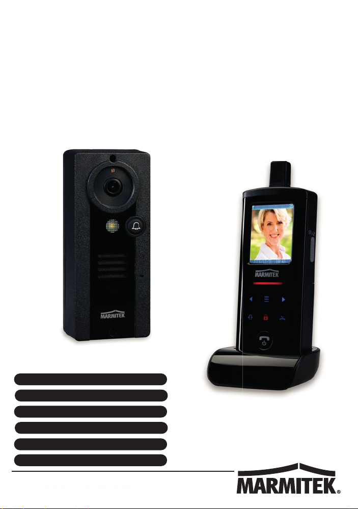
Congratulations on your purchase of the Marmitek Video DoorPhone 210.
Your Video DoorPhone 210 has been manufactured and checked under the
strictest possible quality control to ensure that each Video DoorPhone 210
leaves the factory in perfect condition. In the unlikely event you find any
defect or experience any problem, please contact our service centre or
dealer, do not attempt to repair by yourself.
Please read this manual carefully to obtain optimum performance and
extended service life from the system.
FEATURES
x Mobile wireless video doorphone system.
x Always see who's at the door before you open it, from anywhere in your
home.
x Get a good view of people day and night, with a digitally adjustable
camera angle, zoom feature and LED lighting.
x Interference-free coverage, anywhere in your home.
x Easy installation, using existing wiring.
x Including missed call notification and automatic image storage of last 10
visitors.
x Rugged, weatherproof housing.
x Open the door remotely by electric door opener (optional).
x Selectable doorbell warning: audio, visual and/or vibrate.
x Digital transmission - ensures interference-free calls.
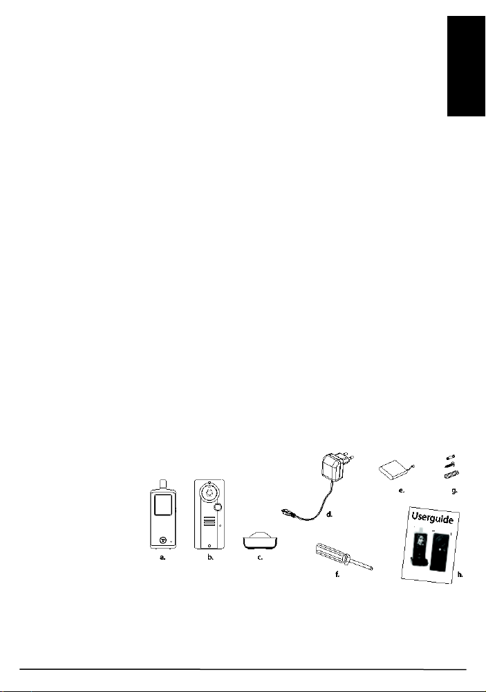
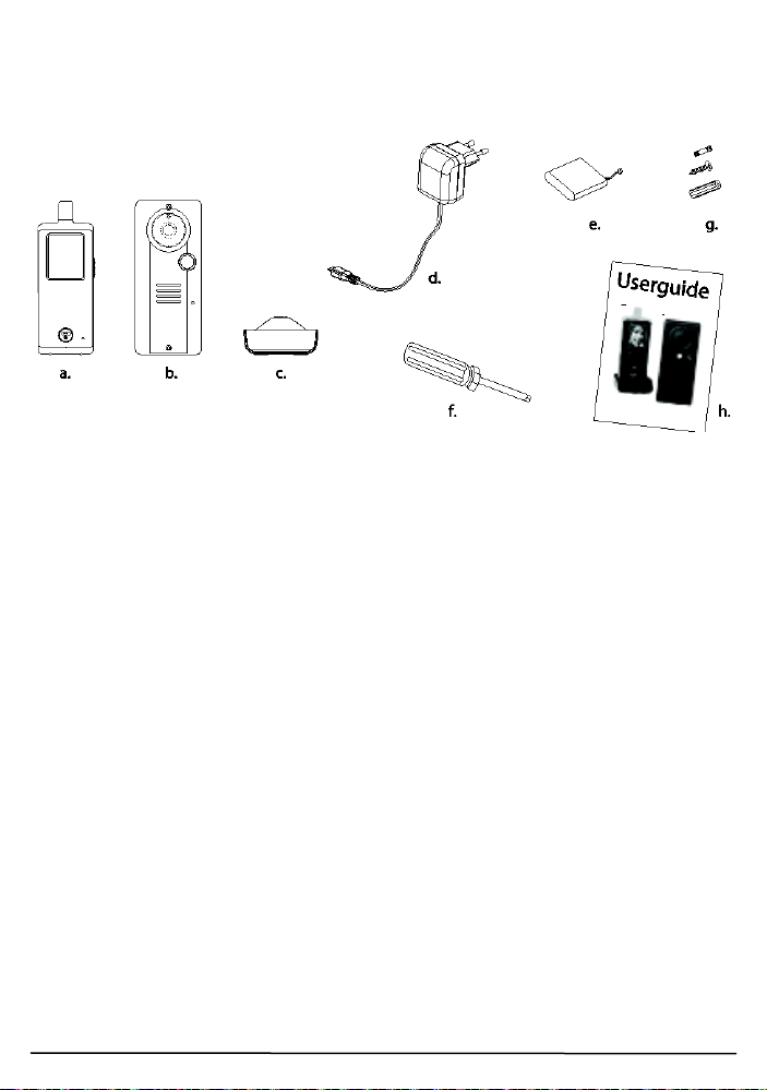
SET CONTENTS
a. Handset
b. Door Unit
c. Charger stand
d. Switching power
supply for
charger stand
e. Rechargeable Li
battery pack
(installed in
handset)
f. Tool
g. Screws and rivets
h. Manual
Video DoorPhone 210
Page 6
6
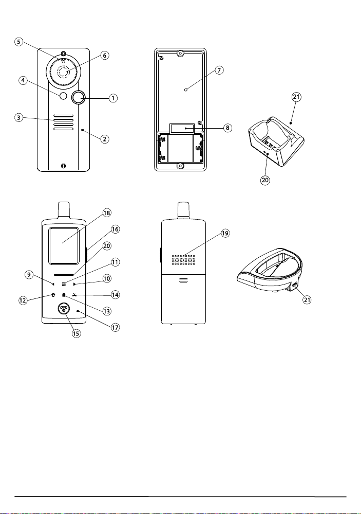
CONTROLS LAYOUT
Charging stand
Door unit
Handset unit
1. Call button
2. Microphone
3. Speaker
4. White illumination LED
5. Light sensor
6. Camera lens
7. Pairing button
8. Terminal block
9. Volume down/Left key
10. Volume up/Right key
11. Menu key
12. Image shift key
13. Door lock open key
14. Missed calls key
15. Hang up and power ON/OFF button
16. Talk and answer button
17. Microphone
18. TFT screen
19. Speaker
20. Power and battery low indicator
21. USB port
© MARMITEK
Page 7
7
ENGLISH
GETTING STARTED
Power Supply
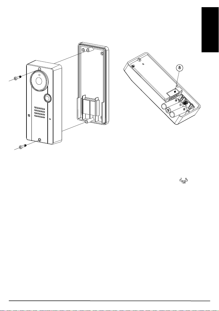
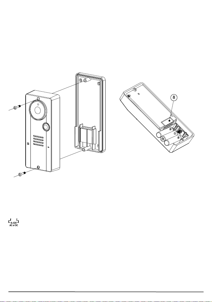
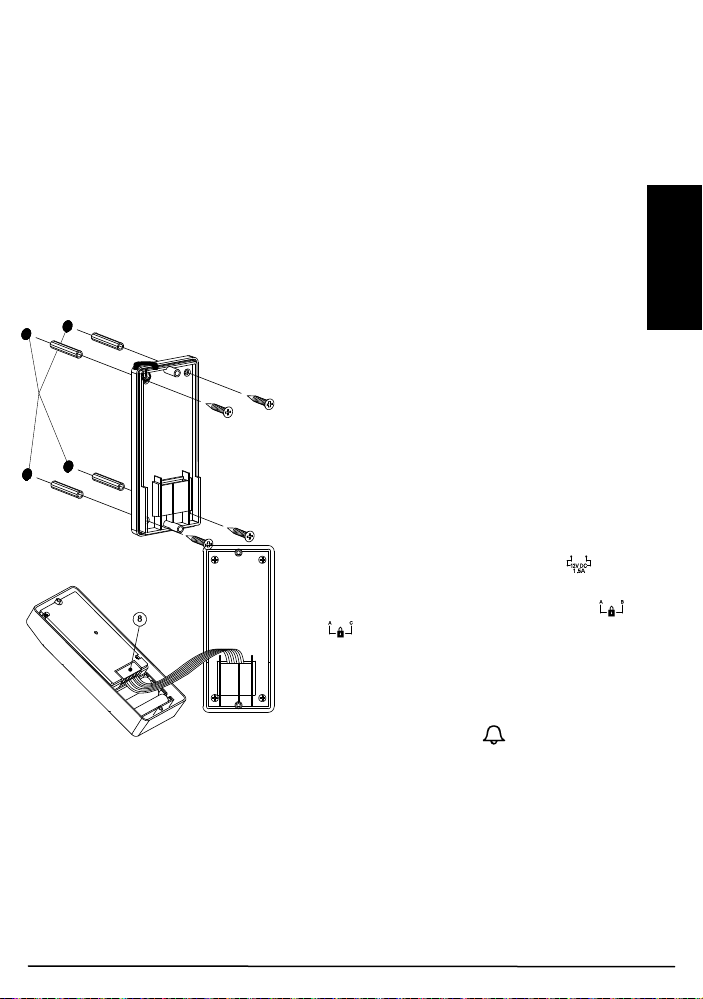
Door unit
With the supplied tool, loosen the screws holding the unit from the mounting
bracket. The screws are made specifically for anti-theft purposes. It is
necessary to keep the tool in a safe place for when you need it later when
replacing batteries. The door unit is powered with 8 to 12V AC or 12V DC.
Connect a power supply to the terminals (8) at the back marked with (not
included).
In case of a power failure, the unit will automatically switch to power from the
alkaline batteries (if installed).
You can use your existing doorbell transformer as power supply, as long as it
can provide 8…12V, AC or 12V DC. When you want to use another 12V
power supply, make sure it has a stable voltage output (Switching adapter
100-240VAC (V) 12VDC) and not a transformer type that has a high no load
voltage!
Backup
Insert three UM-4 size AAA alkaline cells into the battery compartment;
observe correct polarity. We strongly recommend using alkaline batteries
instead of rechargeable batteries because at low temperatures (below 0˚C),
rechargeable ones have poor performance and their capacity will fall.
Please note the alkaline batteries are used only as a backup in case of mains
failure. They can only last for 1 - 2 days under normal operation.
Video DoorPhone 210
Page 8
8
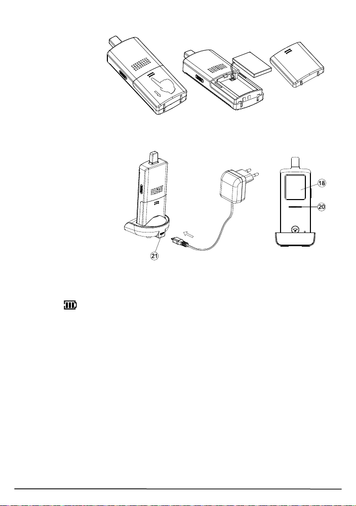
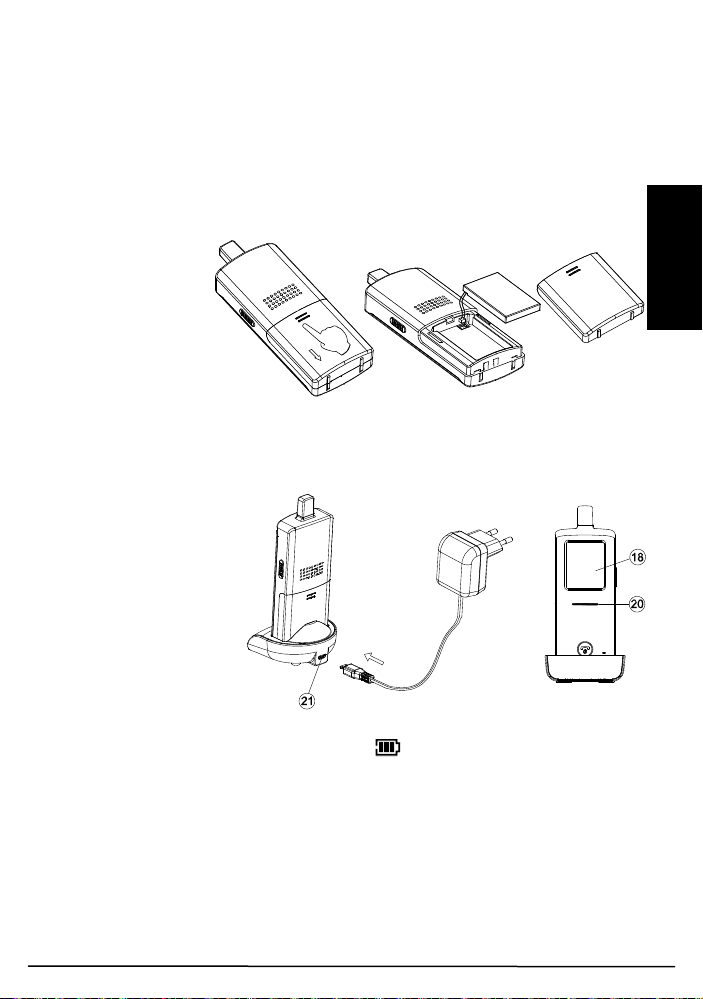
Handset
The supplied Li
polymer battery
pack is already
installed in the
handset. (To
replace the battery,
press down and
slide open the
battery door in the direction as shown, take out the battery pack and
disconnect it from the socket.
With the handset
remaining switched off,
place it onto the charger
stand.
Plug in the supplied AC
switching power supply
into an AC outlet and
connect its output plug
to the USB port (21)
located at the back of
the charger stand.
The power indicator (20)
should light up red during the charging process. Adjust the position of the
handset in the charger stand in case this indicator does not light up. During
charging, in case the screen (18) is turned on, the segments within the
battery icon will flash in turn.
The battery pack should be fully charged within 4 hours when used for the
first time. The power indicator (20) will now go off (if the handset is switched
off) or turn steady blue (if the handset is switched on).
Now the unit can be switched on and is ready for operation. Either taking out
the unit or keeping it placed in the charger stand will cause no damage to the
battery. In the latter case, when the battery is being consumed and voltage
falls to a certain level, the charger stand will automatically charge up the
battery.
CAUTION: BE SURE THE BATTERY IN THE HANDSET IS A
RECHARGEABLE TYPE BEFORE YOU PLACE IT IN THE CHARGER
STAND, OTHERWISE AN EXPLOSION MAY RESULT.
© MARMITEK
Page 9
9
ENGLISH
Pairing the handset and the door unit
This process is to match the door unit with the handset so that they can
communicate with each other and so that no other devices (even a
doorphone of an identical model) can interfere with your set.
The door unit and handset are already paired when they are shipped from the
factory. However, in case interference still exists, perform pairing again to
achieve better privacy and to avoid false triggering of the door lock from a
nearby doorphone system.
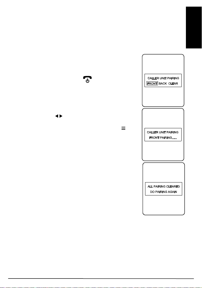
Place the door unit and handset close to each other
within a distance of 1m.
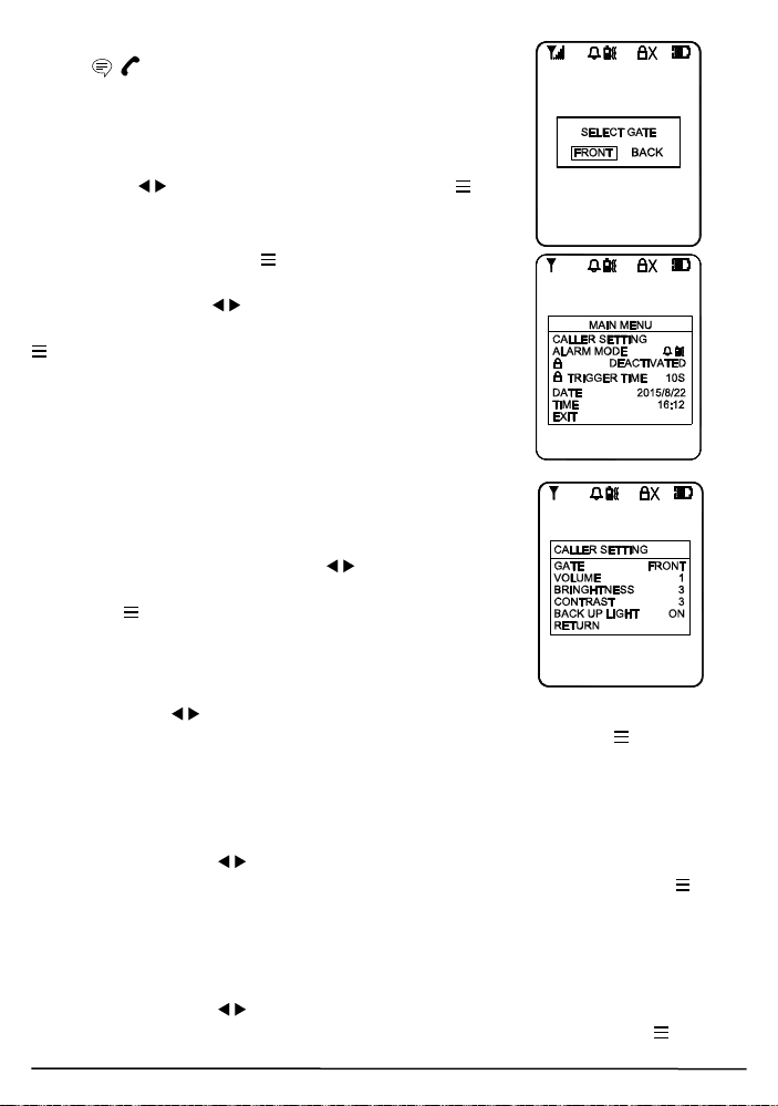
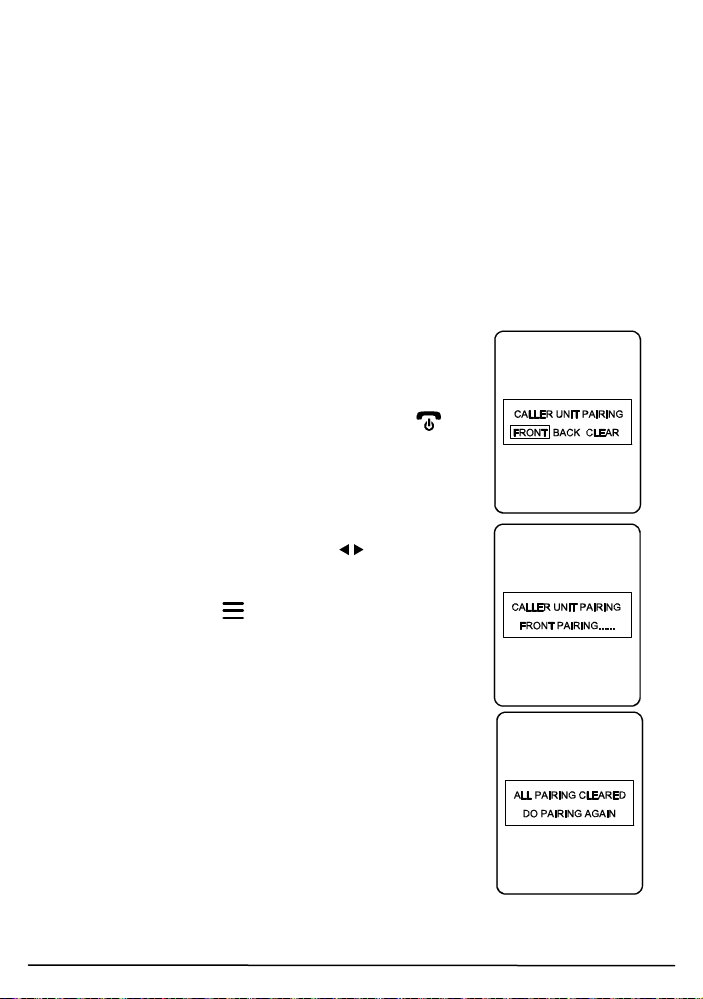
Press and hold the talk/answer button (16), then long
press the power ON/OFF button (15) to switch on
the unit. The screen (18) will show the following:
Use the left/right key (9)(10) to select either
“FRONT” (represent front gate), “BACK” (represent
back gate) or “CLEAR”, then touch the menu key
(11) to confirm. The power indicator (20) should now
flash rapidly, showing the handset has entered pairing
mode.
In case “CLEAR” is selected, all the originally paired
door units will be cleared and you will then need to
perform pairing again.
Now install alkaline batteries or connect 12V DC to the
door unit. (If the door unit was already on, do a
powercycle.) Then short press the pairing button (7)
located at the back.
WARNING: The pairing button (7) must be pressed
within 30 sec once you supply power to the door unit, otherwise pairing
will not be successful.
Once the handset and the door unit are successfully paired, the image
captured by the camera lens (6) will be shown in the screen (18) of the
handset. The doorphone is now ready for operation. If the pairing process is
not successful (the screen (18) remains blue), repeat the procedures from
step 2 again. Remember when you add a second door unit to the system (for
back gate use), it is necessary to perform the pairing process and select
“BACK”. The original front gate unit does not need to be paired again.
Video DoorPhone 210
Page 10
10
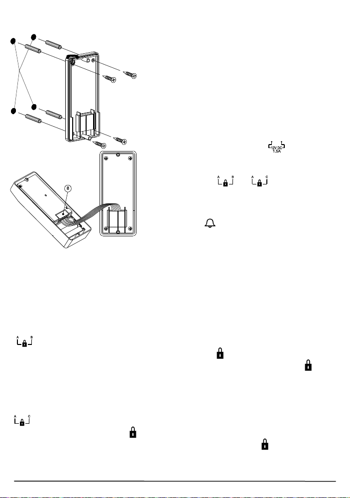
Mounting of door Unit
Drilled holes
Insert the plugs into the holes
(for concrete wall only)
Select a location near your door entrance
where the surface is not too rough. We
recommend that you do some polishing to
get a plane surface or otherwise the unit
may not be able to mount properly.
It should be noted that the mounting bracket
is not installed on metal screening surfaces
nor in the vicinity of other electronic devices
that may reduce the operating range. Using
the supplied self tap screws, fix the
mounting bracket onto the wall.
Connect the terminals marked of the
12V DC power supply at the back of the
door unit. In addition, there are also
terminals marked and for
connecting to an electric door latch which
can be remotely opened by the handset.
When the DC power supply is connected,
the call button (1) will be illuminated. The
electric door latch opening feature will not
operate when using the backup alkaline
batteries so as to keep long battery life.
CAUTION: When using the DC supply, in case the electric door latch
does not function, reverse the polarity it is connected to and try again.
(The two most common types of electric door latch on the market are either
“always close” or “always open”.)
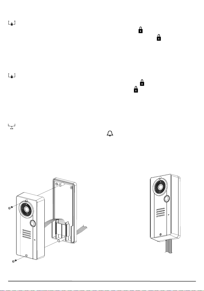
Always close
These two terminals normally provide a 12V supply. During
communication, once the door lock opening button (13) is pressed, this
voltage will drop to 0V temporarily for duration of time as specified by the
TRIGGER TIME function.
Always open
These two terminals normally provide 0V. During communication, once
the door lock opening button (13) is pressed, the terminals will provide a
12V supply temporarily for duration of time as specified by the TRIGGER
TIME function.
Under no circumstances should AC mains Voltage be directly connected to
the terminal blocks (8)!
© MARMITEK
Page 11
11
ENGLISH
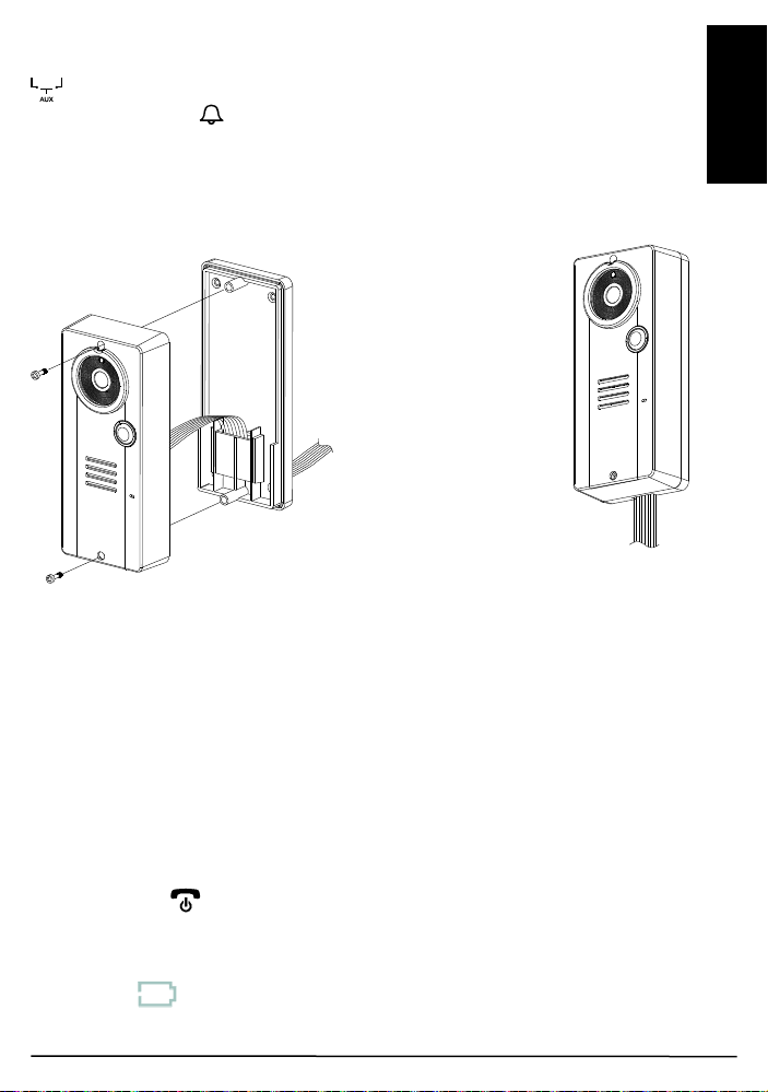
Auxiliary terminal
To DC supply
door lock
The connecting wire can
opening at
concealed in the wall
These two terminals act like a switch and will be short circuited as long as
the doorbell button (1) is pressed, however, there is no voltage supply
from these terminals. They can be used to trigger a conventional door chime
or a courtesy light at the entrance.
Now insert the 3 pcs AAA (UM-4) alkaline batteries into the battery
compartment as this can serve as a battery back-up in case the 12V DC
supply fails.
and electric
come out from the
the bottom in case not
Install the back of the door unit onto the mounting bracket using the supplied
tool.
The door unit is housed in a high impact ABS/PC cabinet, which can achieve
the professional grade ruggedness required in most outdoor applications.
Rubber gaskets seal around all of the joints keep out dust, rain, snow and
spray, assuring years of reliable operation even in harsh environments. The
unit meets to IP-54 standard and can operate from -20˚C to 50˚C.
OPERATION
ON / OFF
Switch on the handset by a long press (over 3 seconds) of the Power
ON/OFF button (15). (Long press the same button again in case you
want to switch off the unit.)
The power indicator (20) will light up blue. In case the Li battery has run
down, the power indicator will start flashing blue. At the same time, the
battery icon shown on screen (18) will become empty and flashing. Place
the unit into the charger stand to charge up the battery.
Video DoorPhone 210
Page 12
12
During standby mode, a short press of the Talk/answer
button / (16) will initiate communication with the
door unit and wake up the screen (18) showing the
view as captured by the lens (6) (In case a backgate
caller unit has been installed, the screen (18) will
prompt you to select “FRONT” or “BACK”. Use the
left/right key (9) (10) to select and menu key (11)
to confirm.).
Long touch the menu key (11) for over 2 sec to
show the menu on the screen (18):
Use the left/right key (9) (10) to select the
parameters to be set, then short touch the menu key
(11) to confirm. The selectable values now show
yellow while the parameter description resumes the
light blue colour.
CALLER SETTING
GATE
This will select the door unit you prefer to change the
settings for. Use the left/right key (9) (10) to select
between FRONT or BACK gate, then short touch the
menu key (11) to confirm your setting.
VOLUME
This will set the speaker volume of the door unit. Use
the left/right key (9) (10) to select between the 5 levels with 1 being the
lowest and 5 being the highest volume. Short touch the menu key (11) to
confirm your setting.
BRIGHTNESS
This will set the brightness of the visitor’s image as shown on the screen (18).
Use the left/right key (9) (10) to select between the 5 levels with 1 being
the lowest and 5 being the highest brightness. Short touch the menu key
(11) to confirm your setting.
CONTRAST
This will set the contrast of the visitor’s image as shown on the screen (18).
Use the left/right key (9) (10) to select between the 5 levels with 1 being
the lowest and 5 being the highest contrast. Short touch the menu key (11)
to confirm your setting.
© MARMITEK
Page 13

13
ENGLISH
GATE LIGHT
For the door unit installed at a location where there is not enough illumination
even at day time, this function can be used to switch on the white LED every
time the call button (1) is being pressed which serves as a back-up light to
illuminate the face of your visitor.
Use the left/right key (9) (10) to select between ON, OFF or AUTO. Short
touch the menu key (11) to confirm.
ON: gate light always on once the call button (1) is pressed.
OFF: gate light always off.
AUTO: gate light will go on, once the call button (1) is pressed and when
the light sensor (5) detects a low light intensity.
After completing the settings, select RETURN to go back to the main menu.
ALARM MODE
This will set the method of alert when a visitor calls, either with a ding-dong
sound or vibration or both. Use the left/right key (9) (10) to select between
(ding-dong sound and vibration) or (ding-dong sound only) or
(vibration only). Short touch the menu key (11) to confirm.
The corresponding icon will be shown on the top of the screen (18). In case
blank is selected, no ding-dong sound and vibration alert will be provided;
only the visitor’s image will be shown on the screen (18) when someone
calls.
DOOR LOCK OPEN
This is to activate or deactivate the door lock open key (13). Use the
left/right key (9) (10) to select between “ACTIVATE” or “DEACTIVATE”,
Short touch the menu key (11) to confirm. In case DEACTIVATE is
selected, the icon will show up at the top part of the screen (18).
TRIGGER TIME
This is the duration time for how long the door lock is being triggered. Use the
left/right key (9) (10) to select between 2, 5, 10, 20 or 25 seconds. Short
touch the menu key (11) to confirm.
DATE/TIME
This will set the internal clock. Use the left/right key (9) (10) to set the
year/month/date as well as the hour/minute, touch the menu key (11) to
confirm your setting. In case the Li battery has totally run down, the internal
clock will stop and it is necessary to set the time again after the battery is
charged up.
Video DoorPhone 210
Page 14
14
EXIT
Select this parameter to exit from the menu, short touch the menu key (11)
to confirm. Alternatively, in case no key is being touched within a period of 10
sec, the menu will exit from the screen (18) automatically.
To return to standby mode and switch off the screen (18), short press the
power/hang up button (15). Alternatively, if no key is being touched for
over 1 min, the handset will return to standby mode automatically.
During conversation and when the menu is not shown on the screen (18), the
sound volume heard through the speaker (19) can also be adjusted using the
left/right key (9) (10) and the corresponding volume bar graph is shown on
the screen (18). Please note the loudness of the door chime is fixed and
cannot be adjusted.
Make sure there is power supplied to the caller unit (by either 12V DC or
alkaline batteries). Now press the Call button (1), a ding-dong tone will be
heard. Until a handset answers the call, the ding-dong tone will be heard
periodically, reminding the visitor to keep waiting. In case there is no answer
after 30 seconds, the caller unit ends the call by itself. Press the Call button
(1) to initiate the call again.
N.B. In case there are two caller units (frontgate and backgate), only the unit
whose call button (1) is first pressed will send out a call signal to handset,
the remaining unit will be kept in standby mode until the conversation is over.
If its call button (1) is pressed during this period, a two “Be-Be” sound will
be heard, indicating the unit is under hold mode.
Once the call is being answered, the ding-dong tone stops ringing.
Conversation can now be conducted by speaking into the microphone (2).
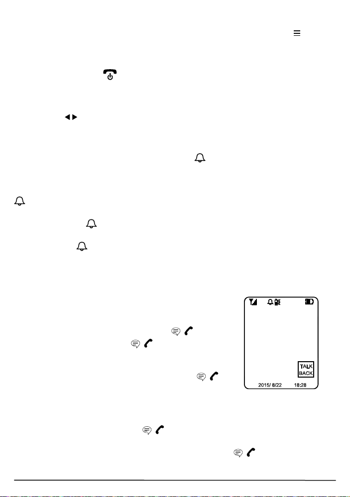
Upon receiving a call, the screen (18) will show the
image of the visitor, but audio communication with the
visitor will not be initiated unless the call is answered by
a short press of the Talk/answer button / (16).
Once the Talk/answer button / (16) is pressed,
conversation is now possible and the voice of the visitor
can be heard from the speaker (19). To talk back to the
visitor, press and hold the Talk/answer button /
(16) and speak towards the microphone (17) once you
see the text “TALK BACK” appear at the lower right corner of the screen (18)
(If you speak before seeing the text, then it is possible that the visitor may
NOT be able to hear some of your first spoken words.).
Release the Talk/answer button / (16) after you finished speaking to
listen to the visitor. It should be worth noted that the voice of the visitor
cannot be heard while pressing the Talk/answer button / (16). Upon
© MARMITEK
Page 15
15
ENGLISH
finishing the conversation, short press the Power/hang up button (15) to
end the call.
In case you need to get a more magnified image of the visitor, short touch the
menu key (11), then short touch either the left/right key (9) (10) to
achieve a 2x zoom image on the screen (18).
Besides, to get a wider scope of view at the door entrance, you can use the
image shift function. Short touch the image shift key (12), then use the
left/right key (9) (10) to shift the image on the screen (18).
This system has an automatic end call feature. In case the resident does not
talk back to the visitor (i.e. press the Talk/answer button / (16)) for over
60 sec, the call will be ended automatically. Such a feature is useful to
protect your privacy in case you forget to end the call by pressing the
Power/hang up button (15).
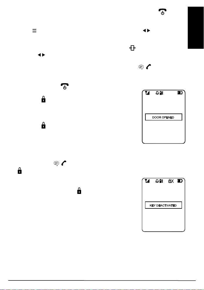
Once a call has been answered, you can use the door
lock open key (13) to remotely open the electric door
latch for the visitor (this function is only available if
there is 12V DC supply to the caller unit and your door
is equipped with an electric latch). Long touch the door
lock open key (13) for over 3 sec and the text “DOOR
OPENED” appears on the screen (18’, showing the
door latch is opened. The text will disappear after 3
sec.)
Under standby mode (i.e. when no call is set up between handset and caller
unit), the electric door latch can also be opened by a short press of the
Talk/answer button / (16), and then a long touch of the door lock open
key (13) for over 3 sec.
To avoid misuse by children, this door lock opening
function can be activated or deactivated. When
deactivated, touching the key (13) will have no effect
and the text “KEY DEACTIVATED” will show on the
screen (18) for 2-3 sec.
Video DoorPhone 210
Page 16
16
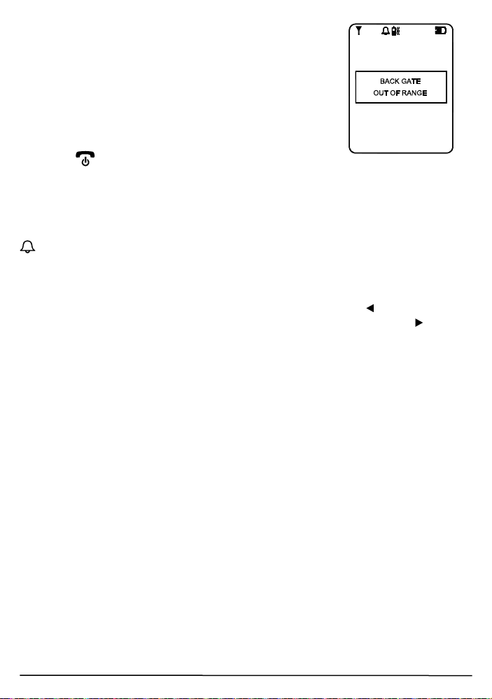
Whenever the handset is located at a spot which is
outside the communication range of the caller unit
(either front or back gate or both), an alarm will be heard
and the screen (18) will show the following:
Such alarm cannot be immediate and will alert you only
when you are out of range for over 2 minutes (when 12V
DC supply is available or 20 minutes if a battery is
used). Once the handset falls back in range, the alarm
will stop automatically. A short press of the power/hang
up button (15) can cut off the alarm sound but the
“out of range” text will continue flashing on the screen (18) until the handset
falls within the range of the caller unit.
N.B. This out of range alert will also occur in case the batteries of the caller
unit run down and its DC power is cut off.
When the Light sensor (5) detects a low light intensity, once the call button
(1) is pressed, the white illumination LED (4) will light up automatically to
illuminate the face of the visitor. This is subjected to “AUTO” being selected
for the GATE LIGHT function menu.
A beep sound will be heard whenever a key is being touched to validate your
entry. To eliminate such a beep sound, long touch the left key (9) until a
second beep is heard. To resume the beep sound, long touch the right (10)
key until a beep sound is heard.
© MARMITEK
Page 17
17
ENGLISH
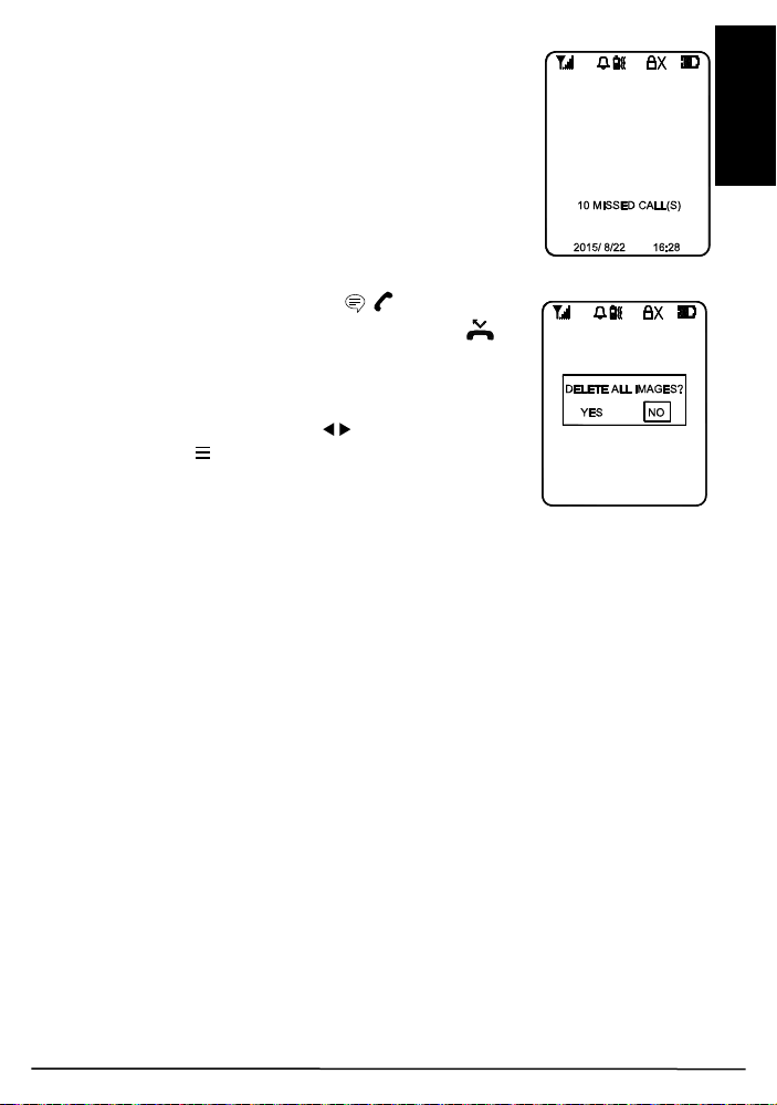
MISSED CALL(S)
Under the circumstances of an unanswered call from a
visitor (e.g. you are away from home), the missed call
indicator will start flashing in standby mode. At the
same time, the text “X MISSED CALL(S)“ will be shown
at the bottom part of the screen (18) whenever it is
woken up (X represents the total number of missed
calls, the maximum number of missed calls that can be
stored is 10, with the most updated entry overriding the
oldest entry).
Short press the Talk/answer button / (16) to initiate
the screen (18). Short touch the missed calls key
(14) to show the 1st image, touch again will show the
subsequent images until after the last recorded image,
the screen (18) will prompt you if you prefer to delete
the images, use the left/right key (9) (10) to select
and the menu key (11) to confirm. In case NO is
selected, the missed calls indicator will continue to
flash until all stored images are deleted.
PRECAUTION
x Use only the supplied AC switching power supply for charging the
handset. Use of another supply may cause damage to the handset.
x Do not mix old and new alkaline batteries in the door unit.
x When not using the Video DoorPhone 210 for a long period of time,
remove all batteries from the handset and the door unit to avoid battery
leakage.
x Do not leave the handset exposed to strong sunlight for a long period of
time or near any heat source, moisture and an excessive dusty
environment.
x Do not open the cabinet; no serviceable parts are inside.
x When using for the first time, switch off the handset and charge up the
supplied battery pack for 4 – 5 hours using the charger stand.
Video DoorPhone 210
Page 18

18
FREQUENTLY ASKED QUESTIONS
The handset and door unit cannot communicate
x The handset and door unit have a different ID code, perform the pairing
process
x The battery has run down. Replace the batteries in the door unit or
recharge the battery in the handset using the charger stand.
The communication distance becomes short
x There are many steel structures between the handset and the door unit.
Relocate the position of the handset.
x Battery has run down. Replace the batteries in the door unit or recharge
the battery in the handset using the charger stand.
Out-of-range alert always on
No power supply to the door unit. Replace the batteries or check the DC
supply to the door unit.
Always showing low battery on the handset
The battery pack is damaged and cannot be recharged. Replace with new
battery pack.
The door latch cannot be remotely opened by handset
x The door lock opening button (13) is deactivated. Activate the door lock
opening button (13).
x No DC supply to the door unit. Check if DC supply is available.
x Wrong connection at terminal block. Make proper connection.
New door unit (backgate) cannot communicate with indoor unit
The new unit is not properly paired to existing unit. Perform pairing process.
The Touch keys have no response
Disconnect the battery from the socket to reset the handset and re-connect
again.
Do you have other questions that have not been resolved by the above
information?
Please go to www.marmitek.com
© MARMITEK
Page 19

19
ENGLISH
TECHNICAL DATA
Handset
Power Rechargeable Li battery pack
800mAh 3.7V
Charger 5V 600mA
Power consumption Stand-by 78mA
Active Transmission mode 190mA
Reception mode 410mA max
Doorbell Selectable audio, visual or vibration alert
Dimensions 50x142x22mm
Door unit
Range Up to 300m in free field, up to 30m through walls
and ceilings.
Backup Power Battery (3x AAA alkaline, for 3 days backup, not
included)
Power adapter 8…12 V DC or AC, min. 500mA without door
opener, 1000mA with door opener (not included)
Frequency 863-870Mhz
Power consumption Stand-by 85mA
Active Transmission mode 200mA
Reception mode 450mA
Material ABS / PC / PMMA
Connection External power 12V AC or DC MAX, 500mA MIN
Make connection 12V, 1A MAX
Break connection 12V, 1A MAX
AUX connector MAX load, 12V/200mA
Ambient temperature - 20° C to + 50° C
IP value IP54
Camera 1/4" CMOS with 300K pixel
Dimensions 57x139x30mm
In order to continue improving the product, Marmitek reserves the right to change
specifications and/or designs without prior notice.
Video DoorPhone 210
Page 20

20
Environmental Information for Customers in the European Union
European Directive 2002/96/EC requires that the equipment bearing this
symbol on the product and/or its packaging must not be disposed of with
unsorted municipal waste. The symbol indicates that this product should be
responsibility to dispose of this and other electric and electronic equipment via
designated collection facilities appointed by the government or local authorities.
Correct disposal and recycling will help prevent potential negative consequences to the
environment and human health. For more detailed information about the disposal of
your old equipment, please contact your local authorities, waste disposal service, or
the shop where you purchased the product.
disposed of separately from regular household waste streams. It is your
COPYRIGHTS
Marmitek is a trademark of Pattitude B.V.
xxxx™ is a trademark of Marmitek B.V. All rights reserved. Every effort has been made
to ensure that the information in this manual is accurate. Marmitek is not responsible
for printing or clerical errors. Copyright and all other proprietary rights in the content
(including but not limited to model numbers, software, audio, video, text and
photographs) rests with Marmitek B.V. Any use of the Content, but without limitation,
distribution, reproduction, modification, display or transmission without the prior written
consent of Marmitek is strictly prohibited. All copyright and other proprietary notices
shall be retained on all reproductions. Other company and product names mentioned
herein may be trademarks of their respective companies. Mention of third-party
products is for informational purposes only and constitutes neither an endorsement nor
a recommendation. Marmitek assumes no responsibility with regard to the performance
or use of these products.
MARMITEK BV - P.O. BOX 4257 - 5604 EG EINDHOVEN
THE NETHERLANDS
© MARMITEK
Page 21

21
DEUTSCH
SICHERHEITSHINWEISE
x Setzen Sie die Komponenten Ihres Systems nicht extrem hohen
Temperaturen oder starken Lichtquellen aus.
x Bei einer zweckwidrigen Verwendung, selbst angebrachten
Veränderungen oder selbst ausgeführten Reparaturen verfallen alle
Garantiebestimmungen. Marmitek übernimmt bei einer falschen
Verwendung des Produkts oder bei einer anderen Verwendung des
Produktes als für den vorgesehenen Zweck keinerlei Produkthaftung.
Marmitek übernimmt für Folgeschäden keine andere Haftung als die
gesetzliche Produkthaftung.
x Dieses Produkt ist kein Spielzeug. Außer Reichweite von Kindern halten.
x Das Produkt niemals öffnen (ausgen.des Batteriefachs): Das Gerät kann
Teile enthalten, worauf lebensgefährliche Stromspannung steht.
Überlassen Sie Reparaturen oder Wartung nur Fachleuten.
x Halten Sie die Batterien außerhalb der Reichweite von Kindern. Liefern
Sie die Batterien als chemischen Kleinabfall ein. Verwenden Sie niemals
alte und neue oder unterschiedliche Typen von Batterien durcheinander.
Wenn Sie das System längere Zeit nicht benutzen, entfernen Sie die
Batterien. Achten Sie beim Einlegen der Batterien auf die Polarität (+ / -):
Ein falsches Einlegen kann zu Explosionsgefahr führen.
x Schließen Sie den Netzadapter erst dann an das Stromnetz an,
nachdem Sie überprüft haben, ob die Netzspannung mit dem auf dem
Typenschild angegeben Wert übereinstimmt. Schließen Sie niemals
einen Netzadapter oder ein Netzkabel an, wenn diese beschädigt sind.
In diesem Fall nehmen Sie Kontakt mit Ihrem Lieferanten auf.
Video DoorPhone 210
Page 22

22
INHALTSVERZEICHNIS
SICHERHEITSHINWEISE ............................................................................ 21
INHALTSVERZEICHNIS ............................................................................... 22
EINFÜHRUNG .............................................................................................. 23
FUNKTIONEN .............................................................................................. 23
INHALT DES SETS ...................................................................................... 24
BEDIENUNGSÜBERSICHT ......................................................................... 25
LOS GEHT’S ................................................................................................ 26
SPEISUNG ................................................................................................ 26
AUSSENSTATION ................................................................................ 26
Back-Up: ................................................................................................... 27
HANDGERÄT ........................................................................................ 27
HANDGERÄT UND AUSSENSTATION PAAREN .................................... 28
MONTAGE DER AUSSENSTATION ........................................................ 29
Immer geschlossen ................................................................................ 30
Immer offen ........................................................................................... 30
Extra Anschluss ..................................................................................... 30
BEDIENUNG ................................................................................................ 31
EIN/AUS .................................................................................................... 31
BESUCHER EINSTELLUNG ........................................................................ 32
GATE (TÜR) .............................................................................................. 32
LAUTSTÄRKE ........................................................................................... 32
HELLIGKEIT ............................................................................................. 32
KONTRAST ............................................................................................... 32
TÜRBELEUCHTUNG ................................................................................ 32
ALARMMODUS ........................................................................................ 33
TÜRSCHLOSS OFFEN ............................................................................. 33
TRIGGER TIME ........................................................................................ 33
DATE/TIME (Datum/Zeit) .......................................................................... 33
EXIT (Ende) .............................................................................................. 34
VERPASSTE(R) AUFRUF(E) ................................................................... 37
VORSORGEMASSNAHMEN .................................................................... 37
HÄUFIG GESTELLTE FRAGEN ................................................................... 38
TECHNISCHE DATEN ................................................................................. 39
© MARMITEK
Page 23

23
DEUTSCH
EINFÜHRUNG
Herzlichen Glückwunsch zum Erwerb dieser digitalen, drahtlosen
Türsprechanlage. Ihr Video DoorPhone 210 wurde unter den strengsten
Qualitätsanforderungen hergestellt und kontrolliert, sodass ein jedes System
in makellosem Zustand das Werk verlässt. Für den unwahrscheinlichen Fall,
dass Sie dennoch einen Defekt oder ein Problem entdecken bitten wir Sie,
sich mit Ihrem Händler in Verbindung zu setzen. Versuchen Sie niemals das
Problem selbst zu beheben.
Bitte lesen Sie diese Anleitung vor Ingebrauchnahme sorgfältig durch, um
einen Höchstwert an Leistung und Lebensdauer Ihres Video DoorPhone 210
zu gewährleisten.
FUNKTIONEN
x Mobile und drahtlose Video-Türsprechanlage
x Immer und überall im Haus direkt sehen wer klingelt, bevor Sie die Tür
öffnen.
x Personen sowohl am Tag wie nachts gut sichtbar durch digital
einstellbaren Kamerawinkel, Zoom-Funktion und LED Beleuchtung.
x Überall im Haus störungsfreie Übertragung.
x Einfache Montage über vorhandene Kabel.
x Einschließlich Meldungen für verpasste Anrufe und automatische
Bildspeicherung der letzten 10 Besucher.
x Solides und witterungsbeständiges Gehäuse.
x Türklingelsignal wählbar akustisch, optisch und/oder vibrieren
x Öffnen der Tür über eine elektrische Fernbedienung (optional erhältlich)
x Wählbare Türklingelsignale - akustisch, optisch und/oder vibrieren
(WEB)
x Digitale Übermittlung - sorgt für störungsfreie Gespräche (WEB)
Video DoorPhone 210
Page 24
24
INHALT DES SETS
a. Handgerät
b. Türeinheit
c. Ladeschale
d. Schaltnetzteil für Ladeschale
e. Wieder aufladbare Li-ion Batterie (im Handgerät enthalten)
f. Werkzeug
g. Schrauben und Nieten
h. Gebrauchsanleitung
© MARMITEK
Page 25

25
DEUTSCH
Oplaadhouder
Deurunit
BEDIENUNGSÜBERSICHT
Handgerät-Einheit
1. Klingeltaste
2. Mikrofon
3. Lautsprecher
4. Weiße LED-Beleuchtung
5. Lichtsensor
6. Objektiv
7. Paarungstaste
8. Anschlussfläche
9. Volumen leiser/Taste
links
10. Volumen lauter/Taste
rechts
11. Menütaste
Video DoorPhone 210
12. Bildverschiebungstaste
13. Türschloss öffnen Taste
14. Verpasste Aufrufe Taste
15. Auflegen und EIN/AUS-Taste
16. Gesprächs- und Antworttaste
17. Mikrofon
18. TFT-Bildschirm
19. Lautsprecher
20. Stromversorgung und schwache
Batterie Anzeige
21. USB-Anschluss
Page 26
26
LOS GEHT’S
SPEISUNG
AUSSENSTATION
Lösen Sie die Schrauben, womit die Einheit an die Montageplatte befestigt ist
mit dem enthaltenen Schraubenzieher. Mit den speziellen AntiDiebstahlschrauben ist eine hohe Produktabsicherung gegeben. Bewahren
Sie den Schraubenzieher für den Fall Sie ihn später noch zum Wechseln der
Batterien benötigen, an einem sicheren Ort auf. Die Außeneinheit wird mit
12V Gleichstrom oder 8 bis 12 V Wechselstrom gespeist, der oftmals am
Eingang (Klingeltrafo) vorhanden ist. Schließen Sie die Speisung an die mit
markierten Anschlüsse (8) an der Rückseite an.
Bei einem Stromausfall schaltet die Einheit automatisch auf Speisung durch
Alkali-Batterien um (wenn eingelegt).
Sie können den vorhandenen Türklingeltransformator als Speisung nutzen,
so lang dieser nur 8 … 12V Wechselstrom oder 12V Gleichstrom bieten
kann. Achten Sie, wenn Sie eine andere 12V Speisung nutzen möchten
darauf, dass diese eine stabile Ausgangsspannung hat (schaltender Adapter
100-240VAC (V) 12VDC) und kein Transformatortyp mit einer hohen,
unbelasteten Spannung ist!
© MARMITEK
Page 27
27
DEUTSCH
Back-Up:
Legen Sie drei UM-4 AAA-Alkali-Mangan Batterien ins Batteriefach. Achten
Sie dabei auf die Polarität. Wir empfehlen Ihnen nachdrücklich die
Verwendung von Alkali-Mangan Batterien anstatt wieder aufladbarer
Batterien. Aufladbare Batterien sind bei niedrigen Temperaturen (unter 0˚C)
nämlich recht unzuverlässig und können an Kapazität einbußen.
Achtung: Die Alkali-Mangan Batterien nur im Falle eines Stromausfalls als
Back-up verwenden, sie halten bei normaler Verwendung nur 1 – 2 Tage.
HANDGERÄT
Der enthaltene LiPolymer Akku ist im
Handgerät installiert.
(Zum Wechseln der
Batterien drücken
Sie die
Verschlusstaste
nach unten und schieben das Batteriefach auf. Entfernen Sie nunmehr den
Akku und lösen Sie den Anschluss.)
Stellen Sie das noch ausgeschaltete Handgerät in die Ladeschale
Schließen Sie das schaltende Wechselstromnetzteil an eine Steckdose und
den Anschlussstecker an
den USB Anschluss (21)
an der Rückseite der
Ladeschale an.
Die Ladestandanzeige
(20) wird während des
Ladevorgangs rot
aufleuchten. Passen Sie
die Position des
Handgeräts in der
Ladeschale an, wenn die
Anzeige nicht aufleuchtet. Wenn der Bildschirm (18) eingeschaltet ist,
werden die Segmente in der Batterie-Ikone
Die Batterie muss für die erste Verwendung mindestens 4 Stunden lang
geladen worden sein. Die Ladestandanzeige (20) wird jetzt ausgehen (wenn
das Handgerät ausgeschaltet ist) oder kontinuierlich blau aufleuchten (wenn
das Handgerät eingeschaltet ist).
Das Handgerät kann nun eingeschaltet werden und ist betriebsbereit. Es ist
nicht nachteilig für die Batterien, wenn Sie das Handgerät aus der Schale
entfernen oder es darin stehen lassen. Im letzteren Fall wird die Ladeschale
den Akku automatisch laden wenn der Akku genutzt wird oder der
Spannungsmesser ein bestimmtes, zu geringes Niveau misst.
Video DoorPhone 210
abwechselnd blinken.
Page 28
28
ACHTUNG: PRÜFEN SIE NACH, OB DER AKKU IM HANDGERÄT
WIRKLICH EIN AUFLADBARER IST, BEVOR SIE DAS HANDGERÄT IN
DIE LADESCHALE STELLEN, DA ES SONST ZU EINER EXPLOSION
FÜHREN KÖNNTE.
HANDGERÄT UND AUSSENSTATION PAAREN
Während dieses Prozesses wird die Außenstation mit dem Handgerät
verbunden (gepaart), sodass beide miteinander kommunizieren können und
keine anderen Geräte (auch keine identische Türsprechanlage) bei Ihnen
oder beim Empfang des Signals eine Störung verursachen können.
Die Außenstation und das Handgerät wurden bereits im Werk mithilfe eines
vorprogrammierten Codes aneinander gekoppelt. Wir empfehlen jedoch zur
Gewährleistung Ihrer Privatsphäre und um zu verhüten, dass Sie aus
Versehen das Türschloss eines in der Nähe anwesenden Video DoorPhone
210 aktivieren, beide erneut zu paaren.
Stellen Sie Außenstation und Handgerät nahe, binnen
einem Meter, beieinander auf.
Drücken Sie anhaltend die Gesprächs-/Antworttaste
(16) und daraufhin lange Zeit die Ein-/Aus Taste
(15), um die Einheit einzuschalten. Im Display (18)
werden Sie nachfolgendes sehen:
Verwenden Sie die links/rechts Tasten
"FRONT" (Eingangstür), "BACK" (Hintertür) oder
"CLEAR" (Löschen) auszuwählen und bestätigen Sie
dann mit der Menütaste
(20) wird nun schnell blinken um anzuzeigen, dass das
Handgerät in den Paarungsmodus (Koppelmodus)
gewechselt ist.
Wird "CLEAR" gewählt, so werden alle ursprünglich
gekoppelten Türeinheiten gelöscht und muss erneut
gekoppelt werden.
Legen Sie nunmehr die Alkali-Batterien ein oder
schließen Sie 12V Gleichstrom an die Türeinheit an
(wenn die Türeinheit bereits eingeschaltet war, schalten
Sie den Strom kurz ab und dann wieder ein). Drücken
Sie danach kurz auf die Paarungstaste (7) auf der Rückseite.
(11). Die Speisungsanzeige
(9) (10) um
© MARMITEK
Page 29
29
DEUTSCH
ACHTUNG: Die Paarungstaste (7) muss binnen 30 Sekunden, nachdem
Bohrlöcher
DÜBEL FÜR LÖCHER
die Türeinheit mit Strom versehen wird, gedrückt werden, da die
Kopplung sonst misslingen wird.
Sind Handgerät und Türeinheit erfolgreich gekoppelt, werden die vom
Kameraobjektiv (6) festgelegten Aufnahmen im Bildschirm des Handgeräts
(18) wiedergegeben. Die Türsprechanlage ist nun betriebsbereit. Wenn das
Paarungsverfahren misslungen ist (Bildschirm (18) bleibt blau) wiederholen
Sie das Verfahren ab Schritt 2. Beachten Sie dass, wenn Sie eine zweite
Türeinheit an das System hinzufügen (für die Hintertür) Sie das
Paarungsverfahren mit der Auswahl “BACK“ nochmals durchführen müssen
Die ursprüngliche Haustüreinheit muss nicht noch einmal gekoppelt werden.
MONTAGE DER AUSSENSTATION
Wählen Sie einen Ort nahe der Tür mit nicht
zu rauer Oberfläche. Zur korrekten
Befestigung der Außenstation auf einem
glatten Untergrund empfehlen wir, die
Oberfläche zunächst gut zu säubern.
Berücksichtigen Sie, dass der Halter nicht
auf Metallrosten oder nahe anderer
elektronischer Geräte angebracht werden
darf, um die Funkreichweite nicht zu
verringern. Verwenden Sie die enthaltenen,
selbstschneidenden Schrauben zur
Montage des Halters gegen die Wand.
VERWENDEN (NUR IN
BETONWÄNDEN)
Verbinden Sie die Anschlüsse mit
Markierung der 12V Gleichstromspeisung
mit der Rückseite der Türeinheit. Eine
Markierung finden Sie überdies für
und
den Anschluss an eine elektrische
Türklinke, die über das Handgerät
fernbedient werden kann. Nachdem die
Gleichstromspeisung angeschlossen ist,
wird die Türklingeltaste
(1) beleuchtet
sein. Um die Batteriedauer zu verlängern, ist die Türöffner-Funktion des
elektrischen Türschlosses bei Verwendung von Back-up Alkali-Batterien nicht
verwendbar.
ACHTUNG: Wenn Sie eine Gleichstromspeisung nutzen und das
elektrische Türschloss nicht funktioniert, drehen Sie die Polarität woran das
Türschloss angeschlossen ist dann um und versuchen Sie es erneut.
Die zwei gängigsten Türschlossarten die zurzeit auf dem Markt sind, sind
entweder “immer geschlossen“ oder “immer offen“.
Video DoorPhone 210
Page 30
30
Immer geschlossen
Zur speisung
und zum
elektrischen
türschloss
Wenn nicht in der Wand
Diese zwei Anschlüsse liefern normalerweise 12V. Während des
Gesprächs wird diese Spannung während der durch die
Funktion spezifizierten Zeit zeitweise, sobald die Türöffnertaste
TRIGGER TIME-
(13)
betätigt wird, auf 0V abfallen
Immer offen
Diese zwei Anschlüsse liefern normalerweise 0V. Während des
Gesprächs wird diese Spannung, während der durch die
Funktion spezifizierten Zeit, sobald die Türöffnertaste
TRIGGER TIME-
(13) betätigt wird,
zeitweise 12V betragen. 230V Wechselstrom darf niemals unmittelbar an die
Anschlussblöcke angeschlossen werden (8)!
Extra Anschluss
Diese zwei Anschlüsse fungieren als ein Schalter und werden
kurzgeschlossen, solange die Klingeltaste
Anschlüsse liefern jedoch keine Spannung. Sie können zur Aktivierung einer
konventionellen Türklingel oder Außenbeleuchtung an der Tür verwendet
werden.
Legen Sie jetzt die 3 AAA (UM-4) Alkali-Batterien in das Batteriefach ein, um
diese im Falle eines Ausfalls der 12V Gleichstromspannung als
Reservebatterie zu nutzen.
(1) betätigt wird. Diese zwei
verborgen, kann das
Anschlusskabel durch die
untere Öffnung geführt
werden.
Verwenden Sie den enthaltenen Schraubenzieher zur Befestigung der
Außenstation auf dem Halter.
© MARMITEK
Page 31

31
DEUTSCH
Das Gehäuse der Außenstation ist aus solidem ABS/PC und besitzt die
professionelle Robustheit, die für die meisten Anwendungen im Freien
notwendig ist. Gummidichtungen dichten sämtliche Verbindungen
rundherum ab und halten somit Staub, Regen und Schnee fern. Somit ist ein
jahrelanger und zuverlässiger Betrieb gewährleistet, sogar unter extremen
Umständen. Die Einheit entspricht der IP-54 Norm und kann Temperaturen
zwischen -20˚C bis 50˚C ausgesetzt werden.
BEDIENUNG
EIN/AUS
Schalten Sie das Handgerät ein, indem Sie die Ein/Austaste
anhaltend (gute 3 Sekunden lang) betätigen. (Drücken Sie nochmals
anhaltend dieselbe Taste, wenn Sie die Einheit ausschalten möchten).
Die Stromanzeige (20) wird nun blau aufleuchten. Ist die Li-ion Batterie leer,
so wird die Stromanzeige blau blinken. Im Bildschirm (18) wird gleichzeitig
das Batteriepiktogramm
die Einheit in die Ladeschale, um die Batterie zu laden.
Um die Türeinheit und den Bildschirm (18) zu
aktivieren, drücken Sie im Stand-by-Modus kurz die
Sprechtaste
vom Objektiv (6) festgelegte Bild zeigt. Ist eine
Hintertürklingeleinheit installiert, wird der Bildschirm
(18) fragen, FRONT (Vorne) oder BACK (Hinten)
auszuwählen. Verwenden Sie zur Auswahl der Hausoder Hintertür die links/rechts Taste
bestätigen Sie mit der Menütaste
Drücken und halten Sie die Menütaste
als 2 Sekunden fest, um das Menü auf dem Bildschirm
(18) sichtbar zu machen:
Verwenden Sie zur Auswahl der einzustellenden
Parameter die links/rechts Taste
bestätigen Sie dann kurz mit der Menütaste (11).
Die wählbaren Werte werden jetzt in Gelb angezeigt,
während die Parameterbeschreibung wieder hellblau
wird.
/ (16), sodass der Bildschirm das
Leer sichtbar werden und blinken. Stellen Sie
(9) (10) und
(11).
(11) länger
(9) (10) und
(15)
Video DoorPhone 210
Page 32

32
BESUCHER EINSTELLUNG
GATE (TÜR)
Wählt die Türeinheit, dessen Einstellungen Sie ändern
möchten. Verwenden Sie zur Wahl zwischen FRONT
(Haustür) und BACK (Hintertür) die links/rechts Taste
(9) (10). Drücken Sie zur Bestätigung der
Einstellung kurz die Menütaste (11).
LAUTSTÄRKE
Stellt das Lautsprechervolumen der Türeinheit ein. Verwenden Sie die
links/rechts Tasten
1 die geringste und 5 die höchste Lautstärke ist. Drücken Sie zur Bestätigung
der Einstellung kurz die Menütaste
HELLIGKEIT
Stellt die Helligkeit des Bildes des Besuchers ein, wie im Bildschirm (18)
wiedergegeben. Verwenden Sie die links/rechts Tasten
zwischen den 5 Niveaus zu wählen, wobei 1 die geringste und 5 die höchste
Helligkeit ist. Drücken Sie zur Bestätigung der Einstellung kurz die Menütaste
(11).
KONTRAST
Stellt den Kontrast des Bildes des Besuchers ein, wie im Bildschirm (18)
wiedergegeben. Verwenden Sie die links/rechts Tasten
zwischen den 5 Niveaus zu wählen, wobei 1 der geringste und 5 der höchste
Kontrast ist. Drücken Sie zur Bestätigung der Einstellung kurz die Menütaste
(11).
(9) (10) um zwischen den 5 Niveaus zu wählen, wobei
(11).
(9) (10) um
(9) (10) um
TÜRBELEUCHTUNG
Wurde die Türeinheit an einem Ort, an dem auch tagsüber unzureichend
Licht vorhanden ist, montiert, kann diese Funktion verwendet werden, um bei
jeder Betätigung der Klingeltaste
einzuschalten. Dieses Licht fungiert als Back-up Beleuchtung, um das
Gesicht des Besuchers zu beleuchten.
Verwenden Sie die links/rechts Tasten
OFF (Aus) oder AUTO (automatisch) zu wählen. Drücken Sie zur
Bestätigung der Einstellung kurz die Menütaste
ON: Türlicht schaltet sich immer ein, wenn die Klingeltaste
wird.
(1) die weiße LED-Beleuchtung
(9) (10) um zwischen ON (Ein),
(11).
(1) betätigt
© MARMITEK
Page 33

33
DEUTSCH
OFF: Türlicht immer aus.
AUTO: Türlicht schaltet sich ein, wenn die Klingeltaste (1) betätigt wird
und der Lichtsensor (5) eine geringe Lichtintensität erfasst. .
Wählen Sie nach der Beendung der Einstellungen RETURN, um zum
Hauptmenü zurückzukehren.
ALARMMODUS
Hiermit wird die Warnmethode für einen klingelnden Besucher eingestellt:
Klingelton, vibrieren oder beides. Verwenden Sie die links/rechts Tasten
(9) (10) um zwischen
oder
(nur vibrieren) zu wählen. Drücken Sie zur Bestätigung der
Einstellung kurz die Menütaste (11).
Das dazugehörige Piktogramm wird oben im Bildschirm (18) wiedergegeben.
Wenn nichts eingestellt wurde, wird kein Klingelton oder Vibrationsalarm
gegeben, sondern nur das Bild des Besuchers auf dem Bildschirm (18)
gezeigt werden, wenn jemand klingelt.
TÜRSCHLOSS OFFEN
(Klingelton und vibrieren) oder (nur Klingelton)
Türschloss offen Taste
Türschlosses. Verwenden Sie die links/rechts Taste
zwischen “ACTIVATE“ (aktivieren) und “DEACTIVATE“(deaktivieren) zu
wählen und betätigen Sie dann kurz die Menütaste
Wurde DEACTIVATE ausgewählt, erscheint das Piktogramm oben im
Bildschirm (18).
TRIGGER TIME
Hiermit stellen Sie die Aktivierungszeit des Türschlosses ein. Verwenden Sie
die links/rechts Taste
Sekunden zu wählen. Drücken Sie zur Bestätigung der Einstellung kurz die
Menütaste
DATE/TIME (Datum/Zeit)
Zur Einstellung der internen Uhr. Verwenden Sie die links/rechts Tasten
(9) (10), um Monat und Jahr einzustellen und daraufhin Stunden und
Minuten. Drücken Sie zur dann kurz die Menütaste
Einstellung zu bestätigen. Wenn die Lithium--Ion Batterie gänzlich leer ist,
wird die interne Uhr anhalten und muss die Zeit, nachdem die Batterie wieder
geladen ist, erneut eingestellt werden.
Video DoorPhone 210
(11).
(13) zur Aktivierung oder Deaktivierung des
(9) (10), um
(11) zur Bestätigung.
(9) (10), um zwischen 2, 5, 10, 20 oder 25
(11), um die
Page 34

34
EXIT (Ende)
Wählen Sie diesen Parameter zum Verlassen des Menüs und betätigen Sie
kurz die Menütaste
automatisch nach 10 Sekunden im Bildschirm (18), wenn keine Taste betätigt
wurde.
Um in den Stand-by Modus zurückzukehren und den Bildschirm (18)
auszuschalten, drücken Sie kurz die Auflegen/Ein-Aus Taste
Handgerät kehrt auch automatisch in den Stand-by Modus zurück, wenn über
1 Minute lang keine Taste betätigt wurde.
Die Tonlautstärke kann während des Gesprächs und wenn das Menü im
Bildschirm (18) nicht wiedergegeben wird, auch über den Lautsprecher (19)
mithilfe der links/rechts Tasten
dazugehörige Lautstärke-Balkendiagramm im Bildschirm (18) wiedergegeben
wird. Achtung: Die Lautstärke der Türklingel ist unveränderlich und kann
nicht angepasst werden.
Stellen Sie sicher, dass die Klingeleinheit mit Strom (12V Gleichstrom oder
Alkali-Batterien) gespeist wird. Betätigen Sie jetzt die Klingeltaste
woraufhin ein Klingelton zu hören ist. Bis zur Beantwortung durch ein
Handgerät wird der Klingelton wiederholt zu hören sein, um den Besucher
dazu anzuhalten, zu warten. Wird nach 30 Sekunden nicht auf die Klingel
reagiert, dann beendet die Klingeleinheit das Klingeln selbst. Betätigen Sie
die Klingeltaste
N.B. Sind zwei Klingeleinheiten vorhanden (Haustür und Hintertür), wird nur
die Einheit, dessen Klingeltaste
Klingelsignal zum Handgerät versenden. Die andere Einheit bleibt im Standby Modus, bis das Gespräch beendet ist. Wird während dieser Zeit die
Klingeltaste
dass sich die Einheit im Stand-by Modus befindet.
Der Klingelton stoppt, so wie der Aufruf beantwortet wird. Nun kann ein
Gespräch stattfinden, indem Sie in das Mikrofon (2) sprechen.
(1) betätigt, dann wird ein doppelter Ton hörbar, der angibt,
(11) zur Bestätigung. Das Menü erlischt auch
(15). Das
(9) (10) eingestellt werden, wobei das
(1),
(1), um nochmals zu klingeln.
(1) zuerst betätigt wurde, ein
© MARMITEK
Page 35

35
DEUTSCH
Nach der Entgegennahme eines Gespräch zeigt der
Bildschirm (19) das Bild des Besuchers. Eine AudioKommunikation mit dem Besucher ist jedoch erst dann
möglich, wenn der Anruf durch eine kurze Betätigung
der Sprechtaste
Nachdem die Sprechtaste
kann ein Gespräch stattfinden und ist die Stimme des
Besuchers über den Lautsprecher (19) zu hören. Um
mit dem Besucher zu reden, halten Sie die Sprechtaste
/ (16) fest und reden Sie, sowie Sie den Text "TALK BACK" (antworten)
rechts unten im Bildschirm (18) sehen, in Richtung Mikrofon (17) (wenn Sie
antworten, bevor dieser Text erscheint, ist es möglich, dass der Besucher
den Anfang Ihrer Antwort NICHT hört).
Lassen Sie die Sprechtaste
den Besucher antworten zu lassen. Berücksichten Sie, dass Sie den
Besucher nicht hören können, während Sie die Sprechtaste
betätigen. Drücken Sie am Ende des Gesprächs kurz auf die Auflegen/Ein-
Aus Taste
Wenn Sie das Bild des Besuchers vergrößern möchten, drücken Sie kurz auf
die Menütaste
(9) (10), um ein 2x herangezoomtes Bild im Bildschirm (18) zu erhalten.
Sie können überdies die Bildverschiebungsfunktion verwenden, um den Blick
auf den Eingang zu erweitern. Betätigen Sie kurz die Bildverschiebungstaste
(12) und dann die links/rechts Tasten (9) (10), um das Bild im
Bildschirm (18) zu verschieben.
Dieses System besitzt eine Automatikfunktion zur Beendung von
Gesprächen. Wenn der Bewohner dem Besucher nicht antwortet (d.h. er
drückt die Sprechtaste
das Gespräch automatisch beendet. Eine solche Eigenschaft ist nützlich, da
es Ihre Privatsphäre schützt, wenn Sie vergessen haben, den Aufruf mit der
Auflegen/Ein-Austaste
Nachdem Sie einen Anruf entgegengenommen haben,
können Sie die Türschloss öffnen Taste (13)
verwenden, um das elektrische Türschloss fernbedient
für den Besucher zu öffnen (diese Funktion steht nur
zur Verfügung, wenn es 12V Gleichstromspeisung zur
Klingeleinheit gibt und Ihre Tür mit einem elektrischen
Schloss versehen ist). Halten Sie die Türschloss öffnen
Taste
Text 'TÜR GEÖFFNET' wird im Bildschirm (18)
Video DoorPhone 210
(13) mindestens 3 Sekunden lang fest und der
/ (16 beantwortet wird.
/ (16) betätigt wurde,
/ (16) los, wenn Sie ausgeredet haben, um
/ (16)
(15), um das Gespräch zu beenden.
(11). Jetzt betätigen Sie kurz die links- oder rechts Taste
/ (16) länger als 60 Sekunden nicht), dann wird
(15) Taste zu beenden.
Page 36

36
wiedergegeben, um anzuzeigen, dass das Türschloss geöffnet wird. Der Text
erlischt nach 3 Sekunden.
Im Stand-by Modus (das heißt, wenn kein Aufruf zwischen Handgerät und
Klingeleinheit aktiv ist), kann das elektrische Türschloss auch durch einen
kurzen Tastendruck auf die Sprechtaste
daraufhin mit einem langen, mindestens 3 Sekunden währenden,
Tastendruck auf die Türschloss öffnen Taste (13)
Um Missbrauch durch Kinder zu begegnen, kann die
Funktion zum Öffnen des Türschlosses ein- oder
abgeschaltet werden. Wenn abgeschaltet, wird eine
Betätigung der Taste
erscheint 2-3 Sekunden lang der Text "TASTE
DEAKTIVIERT" im Bildschirm (18).
Befindet sich das Handgerät außer Reichweite der
Klingeleinheit (Haus- oder Hintertür oder beides), wird
ein Alarm ertönen und zeigt der Bildschirm
Nachfolgendes:
Ein solcher Alarm kann nicht unverzüglich ausgelöst
werden und wird Sie nur warnen, wenn Sie länger als 2
Minuten außer Reichweite sind (wenn 12V
Gleichstromspeisung verfügbar ist, oder 20 Minuten bei
Verwendung einer Batterie). Sobald sich das
Handgerät wieder innerhalb der benötigten Reichweite befindet, wird der
Alarm automatisch stoppen. Eine kurze Betätigung der Auflegen/Ein-
Austaste
Reichweite" blinkt weiterhin im Bildschirm (18) bis sich das Handgerät wieder
in Reichweite der Klingeleinheit befindet.
N.B. Diese 'Außer Reichweite" Warntext wird auch wiedergegeben, wenn die
Batterien der Klingeleinheit leer sind oder keine Gleichstromspeisung
vorhanden ist.
Stellt der Lichtsensor (5) eine geringe Lichtintensität fest, wird die weiße LED
Beleuchtung (4) nach Betätigung der Klingeltaste
aufleuchten, um das Gesicht des Besuchers zu beleuchten. Das geschieht
jedoch nur, wenn 'AUTO' für das TÜRBELEUCHTUNG Funktionsmenü
ausgewählt wurde.
Wenn eine Taste betätigt wird, wird ein Pfeifton erklingen, um Ihr
Hereinkommen zu bestätigen. Wenn Sie den Pfeifton beenden möchten,
halten Sie die Taste links
Wenn Sie den Pfeifton fortsetzen möchten, halten Sie die Taste rechts
(10) so lange fest, bis ein Pfeifton erklingt.
(15) kann den Alarm ausschalten, aber der Text “Außer
(13) keine Wirkung zeigen und
(9) so lange fest, bis ein zweiter Pfeifton erklingt.
/ (16) geöffnet werden und
(1) automatisch
© MARMITEK
Page 37

37
DEUTSCH
VERPASSTE(R) AUFRUF(E)
Nach einem unbeantworteten Aufruf eines Besuchers
(z.B. weil Sie nicht zu Hause waren) wird die Anzeige
Verpasster Aufruf im Stand-by Modus blinken. Zugleich
erscheint "X VERPASSTE(R) AUFRUF(E))" unten im
Bildschirm (18) nachdem sich dieser einschaltet (X
zeigt die Anzahl der verpassten Aufrufe an). Die
Höchstanzahl der gespeicherten Aufrufe ist 10, wobei
der aktuellste Aufruf die älteste Registrierung
überschreibt).
Betätigen Sie kurz die Sprechtaste
Bildschirm (18) zu aktivieren. Drücken Sie kurz die
Verpasster Aufruf Taste (14), um das erste Bild
aufzurufen. Bei jedem weiteren Tastendruck wird das
darauffolgende Bild gezeigt, bis der Bildschirm (18) Sie
nach der letzten Aufnahme fragen wird, ob Sie diese
löschen möchten. Verwenden Sie zur Auswahl einer
Option die links/rechts Taste
Menütaste
Anzeige Verpasste Aufrufe weiterhin blinken, bis alle gespeicherten
Aufnahmen gelöscht wurden.
VORSORGEMASSNAHMEN
x Verwenden Sie nur die enthaltene Wechselstromspeisung zum Laden
Ihres Handgeräts. Die Verwendung anderer Schaltnetzteile kann das
Handset beschädigen.
x Verwenden Sie keinen Mix aus alten und neuen Alkali-Batterien für die
Türeinheit.
x Entfernen Sie sämtliche Batterien aus dem Handgerät und der
Türeinheit, wenn Sie das Video DoorPhone 210 längere Zeit nicht
nutzen, um einem möglichen Lecken der Batterien zu begegnen.
x Setzen Sie das Handgerät nicht längerfristig starker Sonneneinstrahlung
oder einer Wärmequelle aus und schützen Sie es vor Feuchtigkeit oder
übermäßigem Staub.
x Öffnen Sie das Gehäuse nicht. Es enthält keine Teile die Sie selbst
warten können.
x Schalten Sie das Handgerät vor der ersten Verwendung aus und laden
Sie die enthaltene Batterie mithilfe der Ladeschale 4-5 Stunden lang auf.
(11), um zu bestätigen). Wenn Sie NEIN wählen, wird die
/ (16), um den
(9) (10) und die
Video DoorPhone 210
Page 38

38
HÄUFIG GESTELLTE FRAGEN
Handgerät und Türeinheit können nicht miteinander kommunizieren
x Handgerät und Türeinheit haben verschiedene ID Codes. Führen Sie
das Paarungsverfahren durch.
x Die Batterie ist leer. Ersetzen Sie die Batterien der Türeinheit oder laden
Sie die Batterie des Handgeräts mithilfe der Ladeschale auf.
Die Kommunikationsentfernung ist zu kurz
x Zwischen Handgerät und Türeinheit befinden sich viele
Stahlkonstruktionen. Stellen Sie das Handgerät an einem anderen Ort
auf.
x Die Batterie ist leer. Ersetzen Sie die Batterien der Türeinheit oder laden
Sie die Batterie des Handgeräts mithilfe der Ladeschale auf.
Außer Reichweite Warnung wird fortwährend wiedergegeben
Keine Speisung zur Türeinheit. Ersetzen Sie die Batterien und kontrollieren
Sie die Gleichstromspeisung zur Türeinheit.
Die Batterie-Warnanzeige im Handgerät wird fortwährend
wiedergegeben
Die Batterie ist beschädigt oder kann nicht geladen werden. Ersetzen Sie die
Batterie durch eine neue.
Das Türschloss kann nicht über das Handgerät geöffnet werden
x Die Türschloss Öffnen Taste (13) ist deaktiviert. Aktivieren Sie die
Türschloss Öffnen Taste (13).
x Keine Gleichstromspeisung zur Türeinheit. Überprüfen Sie ob
Gleichstromspeisung vorhanden ist.
x Falsche Verbindung an den Anschlussblock. Verbinden Sie erneut.
Neue Türeinheit (Hintertür) kann nicht mit der Inneneinheit
kommunizieren
Die neue Einheit ist nicht richtig an die vorhandene Einheit gekoppelt.
Führen Sie das Paarungsverfahren durch.
Die Touchpad-Tasten reagieren nicht
Entfernen Sie die Batterie des Anschlusses, um das Handgerät
zurückzusetzen und stellen Sie erneut eine Verbindung her.
Sie haben weitere Fragen, die mit oben stehenden Informationen nicht
beantwortet wurden?
Weitere Informationen erhalten Sie unter www.marmitek.com
© MARMITEK
Page 39

39
DEUTSCH
TECHNISCHE DATEN
Handgerät
Speisung Wieder aufladbare Lithium-Ionen Batterie
800mAh 3,7V
Ladegerät 5V600mA
Stromverbrauch Stand-by 78mA
Aktiver Übertragungsmodus 190mA
Empfangsmodus 410mA max.
Türklingel Audio, visuell oder vibrieren wählbar.
Maße: 50x142x22mm
Türeinheit
Reichweite Bis zu 300m freies Feld, bis zu 30m durch Wände
und Decken hindurch.
Back-Up Speisung Batterie (3x AAA Alkali, Back-up für 3 Tage, nicht
enthalten)
Speisungsadapter 8…12V DC of AC, min. 500mA ohne Türöffner,
1000mA mit Türöffner (nicht enthalten)
Frequenz 863-870Mhz
Stromverbrauch Stand-by 85mA
Aktiver Übertragungsmodus 200mA
Empfangsmodus 450mA
Material ABS / PC / PMMA
Anschluss Externe Speisung 12V AC oder DC MAX, 500mA
MIN.
Verbinden mit 12V, 1A MAX
Verbindung unterbrechen 12V, 1A MAX
AUX Anschluss MAX laden, 12V/200mA
Umgebungstemperatur -20°C bis +50°C (*)
IP Wert IP54
Kamera 1/4" CMOS mit 300K Pixeln
Maße 57x139x30mm
Hinsichtlich weiterer Produktverbesserungen behält sich Marmitek das Recht vor,
Spezifikationen und/oder Entwürfe ohne vorherige Ankündigung zu ändern.
Video DoorPhone 210
Page 40

40
Umweltinformation für Kunden innerhalb der Europäischen Union
Die Europäische Richtlinie 2002/96/EC verlangt, dass technische
Ausrüstung, die direkt am Gerät und/oder an der Verpackung mit diesem
Symbol versehen ist nicht zusammen mit unsortiertem Gemeindeabfall
regulärem Haushaltmüll getrennt entsorgt werden sollte. Es liegt in Ihrer
Verantwortung, dieses Gerät und andere elektrische und elektronische Geräte über die
dafür zuständigen und von der Regierung oder örtlichen Behörden dazu bestimmten
Sammelstellen zu entsorgen. Ordnungsgemäßes Entsorgen und Recyceln trägt dazu
bei, potentielle negative Folgen für Umwelt und die menschliche Gesundheit zu
vermeiden. Wenn Sie weitere Informationen zur Entsorgung Ihrer Altgeräte benötigen,
wenden Sie sich bitte an die örtlichen Behörden oder städtischen Entsorgungsdienste
oder an den Händler, bei dem Sie das Produkt erworben haben.
COPYRIGHT
Marmitek BV ist ein Warenzeichen von Pattitude
Video DoorPhone 210™ ist ein Warenzeichen von Marmitek BV Alle Rechte
vorbehalten.
Weitergehende Ansprüche sind ausgeschlossen, insbesondere übernimmt Marmitek
BV keine Gewähr für die Richtigkeit des Inhalts dieses Handbuchs.
Urheber- und andere Eigentumsrechte am Inhalt (einschließlich aber nicht beschränkt
auf, Modellnummern, Software, Audio, Video, Text und Fotos begrenzt) liegt bei
Marmitek BV. Jegliche Nutzung von Inhalten, aber ohne Begrenzung, Verteilung,
Vervielfältigung, Änderung, Anzeige oder Übermittlung ohne die vorherige schriftliche
Erlaubnis von Marmitek ist strengstens untersagt. Alle Urheber- und andere
Eigentumsrechte muss auf allen Reproduktionen beibehalten werden.
Die Rechte an anderen in diesem Handbuch erwähnten Marken und Produktnamen
können bei ihren Inhabern liegen und werden hiermit anerkannt. Die Nennung von
Produkten, die nicht von Marmitek sind, dient ausschließlich Informationszwecken und
stellt keine Werbung dar. Marmitek übernimmt hinsichtlich der Auswahl, Leistung oder
Verwendbarkeit dieser Produkte keine Gewähr.
entsorgt werden darf. Das Symbol weist darauf hin, dass das Produkt von
MARMITEK BV - POSTBUS 4257 - 5604 EG EINDHOVEN
NEDERLAND
© MARMITEK
Page 41

41
FRANÇAIS
CONSIGNES DE SÉCURITÉ
• Ne pas exposer les composants de votre système à des températures
extrêmement élevées ou à des sources de lumière trop fortes.
• La garantie n'est plus valable en cas d'usage inapproprié, de
modifications ou de réparations effectuées par des personnes non
agréées. Marmitek se dégage de toute responsabilité du fait des produits
en cas d'usage inapproprié du produit ou d'utilisation non conforme à
l'usage auquel le produit est destiné. Marmitek se dégage de toute
responsabilité en cas de dommage conséquent, autre que la
responsabilité civile du fait des produits.
• Ce produit n'est pas un jouet. Tenir hors de portée des enfants.
• Ne jamais ouvrir le produit (excepté le compartiment à piles) : L'appareil
peut contenir des éléments qui sont sous tension très dangereux. Confier
les réparations et l'entretien exclusivement à un personnel qualifié.
• Tenir les piles hors de portée des enfants. Traiter les piles usagées
comme des petits déchets chimiques. Ne jamais utiliser simultanément
des vieilles piles et des piles neuves, ou des piles de types différents.
Enlever les piles lorsque le système sera mis longtemps hors de service.
Respecter la polarité en insérant les piles (+/-) : une insertion incorrecte
peut engendrer un danger d’explosion.
• Ne brancher l’adaptateur secteur sur le réseau électrique qu’après avoir
vérifié que la tension d’alimentation correspond à la valeur indiquée sur
les plaques d’identification. Ne jamais brancher un adaptateur secteur ou
un câble d’alimentation lorsque celui-ci est endommagé. Dans ce cas,
veuillez contacter votre revendeur.
Video DoorPhone 210
Page 42

42
TABLE DES MATIÈRES
CONSIGNES DE SÉCURITÉ ....................................................................... 41
TABLE DES MATIÈRES ............................................................................... 42
INTRODUCTION .......................................................................................... 43
FONCTIONS ................................................................................................. 43
CONTENU .................................................................................................... 44
APERÇU DU FONCTIONNEMENT .............................................................. 45
PRISE EN MAIN ........................................................................................... 46
ALIMENTATION : ...................................................................................... 46
UNITÉ EXTÉRIEURE ............................................................................ 46
Piles de secours ........................................................................................ 46
COMBINÉ .............................................................................................. 47
INSTALLATION DE L'UNITÉ EXTÉRIEURE ............................................ 49
Toujours fermé....................................................................................... 50
Toujours ouvert ...................................................................................... 50
Prise de connexion supplémentaire ....................................................... 50
COMMANDES .............................................................................................. 51
MARCHE / ARRÊT ................................................................................... 51
CONFIGURATION DE L’UNITÉ EXTÉRIEURE ........................................... 52
GATE (PORTE) ......................................................................................... 52
VOLUME ................................................................................................... 52
NETTETÉ .................................................................................................. 52
CONTRASTE ............................................................................................ 52
ECLAIRAGE DE PORTE .......................................................................... 52
MODE D'ALERTE ..................................................................................... 53
OUVERTURE DE LA SERRURE DE PORTE ........................................... 53
TRIGGER TIME ........................................................................................ 53
DATE/TIME (date/heure) ........................................................................... 53
EXIT (Fin) .................................................................................................. 54
APPEL(S) EN ABSENCE .......................................................................... 57
PRÉCAUTIONS ........................................................................................ 57
FOIRE AUX QUESTIONS ............................................................................ 58
CARACTÉRISTIQUES TECHNIQUES ......................................................... 59
DROITS D'AUTEUR ..................................................................................... 60
© MARMITEK
Page 43

43
FRANÇAIS
INTRODUCTION
Félicitations pour l'achat de ce Système d'Interphone Numérique sans Fil.
Votre Video DoorPhone 210 a été fabriqué et testé conformément aux
contrôles de qualité les plus stricts, afin que chaque système quitte l'usine en
parfait état. Dans le cas improbable où vous décèleriez un défaut ou une
anomalie, veuillez contacter votre distributeur. Surtout n'essayez jamais de
résoudre le problème vous-même.
Veuillez lire attentivement ce manuel d'utilisation afin d'obtenir une
performance optimale et une longue durée d'utilisation de votre Video
DoorPhone 210.
FONCTIONS
x Système d'interphone audio sans fil portable
x Voyez à tout moment et partout dans la maison qui a sonné avant
d’ouvrir la porte.
x Bonne qualité de l’image de jour comme de nuit grâce à l’angle de prise
de vue réglable numériquement, à la fonction zoom et à l’éclairage LED.
x Portée exempte de parasites partout dans la maison.
x Installation aisée par le biais du câblage existant.
x Y compris notification des appels en absence et stockage automatique
des photos des 10 derniers visiteurs.
x Robuste boîtier, résistant aux intempéries.
x Sonnerie au choix : audio, visuelle et/ou vibrante.
x Ouvrez la porte à distance avec un ouvreur de porte électrique
(disponible en option).
x Sonnerie au choix - audio, visuelle et/ou vibrante (WEB)
x Transmission numérique - assure des conversations sans interférences
(WEB)
Video DoorPhone 210
Page 44

44
CONTENU
a. Combiné
b. Unité extérieure
c. Base de charge
d. Adaptateur secteur de la base de charge
e. Pile Li-ion rechargeable (installée dans le combiné)
f. Outils
g. Vis et rivets
h. Notice d’instructions
© MARMITEK
Page 45

45
FRANÇAIS
APERÇU DU FONCTIONNEMENT
Base de charge
Unité extérieure
Combiné
1. Touche d’appel
2. Microphone
3. Haut-parleur
4. Eclairage LED blanc
5. Capteur de luminosité
6. Objectif de la caméra
7. Touche d'appairage
8. Bornier
9. Volume vers le
bas/touche à gauche
10. Volume vers le
haut/touche à droite
11. Touche menu
Video DoorPhone 210
12. Touche de fonction pan
13. Touche d'ouverture de serrure de
porte
14. Touche des appels en absence
15. Touche fin d’appel et marche/arrêt
16. Touche de communication
17. Microphone
18. Ecran TFT
19. Haut-parleur
20. Voyant d’alimentation et de batterie
faible
21. Port USB
Page 46

46
PRISE EN MAIN
ALIMENTATION :
UNITÉ EXTÉRIEURE
Dévissez avec le tournevis fourni les vis avec lesquelles l'unité est fixée sur
le support de montage. Ces vis sont des vis spéciales antivol. C'est pourquoi
il est nécessaire de garder le tournevis dans un endroit sûr, au cas où vous
en auriez besoin ultérieurement pour changer les piles. L'unité extérieure est
alimentée en courant continu 12V ou en courant alternatif 8V à 12V, qui est
souvent disponible à l'entrée (transformateur de sonnette). Connectez
l'alimentation aux bornes repérées
En cas de défaillance d'alimentation, l'unité passe automatiquement à
l'alimentation par piles alcalines (si elles sont installées).
Vous pouvez utiliser votre transformateur de sonnette existant comme
alimentation, tant que celui-ci peut fournir un courant alternatif 8... 12V ou un
courant continu 12V. Si vous souhaitez utiliser une autre alimentation 12V,
assurez-vous que celle-ci ait une tension de sortie stable (adaptateur secteur
100-240VAC (V) 12VDC) et que cela ne soit pas un type de transformateur
haute tension en circuit ouvert.
(8) sur la face arrière.
Piles de secours
Insérez trois piles alcalines UM-4 AAA dans le compartiment à piles. Faites
bien attention à la polarité. Nous conseillons fortement l'utilisation de piles
alcalines au lieu de piles rechargeables. A basses températures (inférieures
à 0˚C) les piles rechargeables sont moins performantes et perdent de leur
capacité.
Attention : les piles alcalines ne sont utilisées comme piles de secours qu’en
cas d’interruption de courant, dans des conditions d'utilisation normales leur
durée de vie n’est que de 1 ou 2 jours.
© MARMITEK
Page 47

47
FRANÇAIS
COMBINÉ
La pile Lithiumpolymère fournie est
déjà installée dans le
combiné. (Pour la
remplacer appuyez
sur la touche de
fermeture vers le
bas, puis faites
glisser le couvercle pour ouvrir. Retirez ensuite la pile et débranchez-la.)
Placez le combiné
encore désactivé sur le
chargeur.
Branchez l’adaptateur
secteur fourni sur une
prise de courant et
branchez la fiche de
sortie sur le port USB
(21) à l’arrière de la base
de charge.
Le voyant de charge (20)
s'allume en rouge
pendant le processus de charge. Modifiez la position du combiné sur la base
de charge si ce voyant de charge ne s'allume pas. Lorsque l’écran (18) est
activé, les segments de l’icône de pile clignoteront en alternance pendant
la charge.
Avant la première utilisation la pile doit être complètement chargée en 4
heures. Le voyant d’alimentation (20) s’éteindra maintenant (si le combiné
est désactivé) ou restera constamment allumé en bleu (si le combiné est
activé).
Le combiné peut maintenant être activé et est prêt à l'emploi. Le fait de retirer
le combiné ou de le laisser sur le chargeur ne peut pas endommager la pile.
Dans le dernier cas, le chargeur commencera automatiquement à charger la
pile si la pile est utilisée et si la tension descend en dessous d'un certain
niveau.
ATTENTION : ASSUREZ-VOUS QUE LA PILE DANS LE COMBINÉ EST
BIEN UNE PILE RECHARGEABLE AVANT DE PLACER LE COMBINÉ SUR
LE CHARGEUR. SINON CELA POURRAIT PROVOQUER UNE
EXPLOSION.
Video DoorPhone 210
Page 48

48
APPAIRAGE DU COMBINÉ À L'UNITÉ EXTÉRIEURE
Ce processus est prévu pour appairer l'unité extérieure au combiné, de sorte
qu'ils puissent communiquer entre eux et qu'aucun autre appareil (même pas
un modèle d'interphone identique) ne puisse provoquer des interférences
chez vous ou perturber la réception de votre signal.
L'unité extérieure et le combiné sont appairés en usine par le biais d'un code
préprogrammé. Nous vous conseillons toutefois de les appairer à nouveau,
pour préserver votre intimité et pour éviter que vous activiez accidentellement
la serrure de porte d'un autre Video DoorPhone 210 qui est installé dans les
environs.
Placez l'unité extérieure et le combiné très près l'un de
l'autre, à moins d'un mètre de distance.
Maintenez la touche de communication (16) enfoncée
et appuyez ensuite longuement sur la touche
marche/arrêt (15) pour activer l’unité. L'écran (18)
affichera les informations suivantes :
Utilisez les touches à gauche/à droite (9) (10) pour
sélectionner "FRONT" (porte d'entrée), "BACK" (porte
arrière) ou "CLEAR" (Supprimer) et appuyez ensuite sur
la touche menu (11) pour valider. Le voyant
d’alimentation (20) clignotera rapidement maintenant,
pour indiquer que le combiné est passé en mode
d'appairage.
Dans le cas où "CLEAR" est sélectionné, toutes les
unités extérieures qui étaient initialement appairées sont
effacées et la procédure d’appairage doit être effectuée
à nouveau.
Insérez maintenant des piles alcalines ou connectez
l’unité extérieure à une alimentation en courant continu
12V. (Si l’unité extérieure était déjà activée, coupez
alors brièvement l'alimentation et remettez sous tension). Appuyez ensuite
brièvement sur la touche d'appairage (7) sur la face arrière.
ATTENTION : La touche d’appairage (7) doit être enfoncée dans les 30
secondes dès que l’unité extérieure est alimentée, sinon l’appairage
échouera.
Dès que le combiné et l’unité extérieure ont été appairés avec succès, les
images capturées par l’objectif de la caméra (6) sont affichées à l'écran (18)
© MARMITEK
Page 49

49
FRANÇAIS
du combiné. L'interphone est maintenant prêt à l'emploi. Si la procédure
Mettez les chevilles dans les
trous (seulement pour les murs
en béton)
d'appairage a échoué (l’écran (18) reste bleu), répétez la procédure depuis
l'étape 2. N'oubliez pas que lorsque vous ajoutez une deuxième unité
extérieure au système (pour une utilisation sur la porte arrière), la procédure
d'appairage doit être effectuée à nouveau, en sélectionnant "BACK". L’unité
extérieure initiale n’a pas besoin d’être à nouveau appairée.
INSTALLATION DE L'UNITÉ EXTÉRIEURE
Choisissez un endroit près de votre porte, là
où la surface n'est pas trop rugueuse. Nous
vous conseillons de bien nettoyer d’abord la
surface afin d'obtenir une surface lisse, sinon
l'unité extérieure risquerait de ne pas être fixée
correctement.
Assurez-vous que le support de montage ne
soit pas fixé sur des grilles métalliques ou à
proximité d'autres appareils électroniques qui
pourraient réduire la portée opérationnelle.
Utilisez les vis autotaraudeuses fournies pour
fixer le support de montage au mur.
Connectez les bornes repérées de
l’alimentation en courant continu 12V sur la
face arrière de l'unité extérieure. Il y a
également des bornes repérées et
pour connecter une serrure de porte
électrique, qui peut être ouverte à distance
par le biais du combiné. Lorsque l’alimentation
en courant continu est connectée, la touche
d’appel (1) s’éclaire. La fonction
d'ouverture de la serrure électrique ne
fonctionne pas lorsque les piles alcalines de secours sont utilisées, afin de
prolonger la durée de vie des piles.
ATTENTION : Si lors de l'utilisation de courant continu le verrouillage de
porte électrique ne fonctionne pas, inversez la polarité là où le verrouillage de
porte est connecté et essayez à nouveau.
Les deux types de verrouillage de porte électrique les plus courants qui sont
actuellement disponibles, sont soit “toujours fermé” ou “toujours ouvert”.
Video DoorPhone 210
Page 50

50
Toujours fermé
Vers
tion
électrique
Le fil de connexion peut
sortir de l'ouverture en bas
s’il n’est pas dissimulé dans
le mur
Ces deux bornes fournissent normalement une tension de 12V. Dès que
la touche de déverrouillage de porte (13) est enfoncée, cette tension
passera durant la communication temporairement à 0V, pendant le temps qui
est spécifié par la fonction TRIGGER TIME.
Toujours ouvert
Ces deux bornes fournissent normalement une tension de 0V. Dès que
la touche de déverrouillage de porte (13) est enfoncée, cette tension
passera durant la communication temporairement à 12V, pendant le temps
qui est spécifié par la fonction TRIGGER TIME.
Il ne faut en aucun cas connecter le courant alternatif 230V directement aux
borniers (8)!
Prise de connexion supplémentaire
Ces deux prises de connexion fonctionnent comme un interrupteur et
elles seront court-circuitées tant que le bouton de sonnette (1) est
enfoncé. Toutefois ces prises de connexion ne fournissent pas de tension.
Elles peuvent être utilisées pour activer une sonnette de porte
conventionnelle ou l'éclairage extérieur près de la porte.
Insérez les 3 piles alcalines AAA (UM-4) dans le compartiment à piles, de
sorte qu'elles puissent servir de piles de secours au cas où l'alimentation en
courant continu 12V serait défaillante.
l’alimenta
en courant
continu et la
serrure de
porte
Utilisez le tournevis fourni pour fixer le support de montage au mur.
© MARMITEK
Page 51

51
FRANÇAIS
L'unité extérieure est logée dans un boîtier robuste en ABS/PC qui répond à
la robustesse professionnelle qui est requise pour la plupart des applications
à l'extérieur. Des joints en caoutchouc assurent l'étanchéité des jonctions
tout autour et empêchent ainsi la poussière, la pluie et la neige de pénétrer
dans le boîtier. Cela garantit des années de fonctionnement fiable, même
dans des conditions difficiles. L'unité répond à la norme IP-54 et fonctionne à
des températures allant de -20 ˚C à 50 ˚C.
COMMANDES
MARCHE / ARRÊT
Activez le combiné en maintenant la touche Marche/Arrêt (15)
longuement enfoncée (plus de 3 secondes). (Appuyez encore une fois
longuement sur la même touche si vous souhaitez désactiver l’unité).
Le voyant d’alimentation (20) s’allumera maintenant en bleu. Dans le cas où
la pile Li-ion est vide, le voyant d’alimentation clignotera en bleu. En même
temps, l’icône de pile vide apparaîtra à l’écran (18) et commencera à
clignoter. Placez l’unité sur la base de charge pour recharger la pile.
Appuyez, en mode veille, brièvement sur la touche de
communication / (16) pour établir la
communication avec l'unité extérieure et activer l'écran
(18) afin d’afficher les images capturées par l’objectif
(6). (Si une sonnette est installée sur la porte arrière,
l’écran (18) demandera de sélectionner FRONT (Porte
d'entrée) ou BACK (Porte arrière). Utilisez les touches
à gauche/à droite (9) (10) pour sélectionner une
option et la touche menu (11) pour la valider).
Appuyez sur la touche menu (11) pendant plus de 2
secondes afin d’afficher le menu à l’écran (18) :
Utilisez les touches à gauche/à droite (9) (10) pour
sélectionner les paramètres de réglage et appuyez
ensuite brièvement sur la touche menu (11) pour les
valider. Les valeurs sélectionnables sont maintenant
affichées en jaune, tandis que la description des
paramètres redevient bleu clair.
Video DoorPhone 210
Page 52

52
CONFIGURATION DE L’UNITÉ
EXTÉRIEURE
GATE (PORTE)
Cela permet de sélectionner l'unité extérieure dont
vous souhaitez modifier les paramètres. Utilisez les
touches à gauche/à droite (9) (10) pour
sélectionner entre FRONT (porte d'entrée) et BACK
(porte arrière) et appuyez ensuite brièvement sur la
touche menu (11) pour valider le réglage.
VOLUME
Cela permet de régler le volume du haut-parleur de l'unité extérieure. Utilisez
les touches à gauche/à droite (9) (10) pour sélectionner entre les 5
niveaux sonores, 1 étant le niveau de volume le plus faible et 5 le plus élevé.
Appuyez brièvement sur la touche menu (11) pour valider le réglage.
NETTETÉ
Cela permet de régler la netteté de l’image du visiteur qui est affichée sur
l’écran (18). Utilisez les touches à gauche/à droite (9) (10) pour
sélectionner entre les 5 niveaux de netteté, 1 étant le niveau de netteté le
plus faible et 5 le plus élevé. Appuyez brièvement sur la touche menu (11)
pour valider le réglage.
CONTRASTE
Cela permet de régler le contraste de l’image du visiteur, qui est affichée sur
l’écran (18). Utilisez les touches à gauche/à droite (9) (10) pour
sélectionner entre les 5 niveaux de contraste, 1 étant le niveau de contraste
le plus faible et 5 le plus élevé. Appuyez brièvement sur la touche menu
(11) pour valider le réglage.
ECLAIRAGE DE PORTE
Si l'unité extérieure est installée à un endroit où la lumière est insuffisante
même pendant la journée, cette fonction peut être utilisée chaque fois que
l’on appuie sur le bouton d’appel (1) pour allumer l'éclairage LED blanc.
Cet éclairage est utilisé comme éclairage de secours pour éclairer le visage
du visiteur.
Utilisez les touches à gauche/à droite (9) (10) pour sélectionner ON
(Allumé), OFF (Eteint) ou AUTO (automatique). Appuyez brièvement sur la
touche menu (11) pour valider votre choix.
© MARMITEK
Page 53

53
FRANÇAIS
ON : l’éclairage de porte s’allume toujours si l’on appuie sur le bouton d’appel
(1).
OFF : l’éclairage de porte est toujours éteint.
AUTO: l’éclairage de porte s’allume si l’on appuie sur le bouton d’appel
(1) et lorsque le capteur de luminosité (5) détecte une faible intensité
lumineuse.
Après avoir terminé les paramétrages, sélectionnez RETURN pour revenir au
menu principal.
MODE D'ALERTE
Cela permet de programmer le mode d'alerte lorsqu'un visiteur sonne :
sonnerie, vibrations ou les deux. Utilisez les touches à gauche/à droite
(9) (10) pour sélectionner entre (sonnerie et vibrations) ou
(seulement sonnerie) ou (seulement vibrations). Appuyez brièvement sur
la touche menu (11) pour valider votre choix.
L’icône correspondante est affichée en haut de l'écran (18). Si cette option
est laissée en blanc, il n’y aura ni sonnerie ni vibrations lorsque quelqu’un
sonnera à la porte ; seule l'image du visiteur sera à affichée à l'écran (18).
OUVERTURE DE LA SERRURE DE PORTE
Cela permet d’activer ou de désactiver la touche d'ouverture de serrure de
porte (13). Utilisez les touches à gauche/à droite (9) (10) pour
sélectionner "ACTIVATE" (Activer) et "DEACTIVATE (Désactiver) et appuyez
ensuite brièvement sur la touche menu (11) pour valider votre choix. Si
vous avez sélectionné DEACTIVATE, l’icône est affichée en haut de
l'écran 18).
TRIGGER TIME
C’est le temps d’activation de la serrure de porte. Utilisez les touches à
gauche/à droite (9) (10) pour sélectionner 2, 5, 10, 20 ou 25 secondes.
Appuyez ensuite brièvement sur la touche menu (11) pour valider votre
choix.
DATE/TIME (date/heure)
Cela permet de régler l'horloge interne. Utilisez les touches à gauche/à droite
(9) (10) pour sélectionner le mois et l’année, puis les heures et les
minutes. Appuyez ensuite brièvement sur la touche menu (11) pour valider
le réglage. Si la pile lithium-ion est complètement vide, l'horloge interne
s’arrêtera et il faudra reconfigurer l’heure et la date après que la pile ait été
rechargée.
Video DoorPhone 210
Page 54

54
EXIT (Fin)
Sélectionnez ce paramètre pour quitter le menu, appuyez brièvement sur la
touche menu (11) pour valider. Le menu disparaît automatiquement de
l’écran (18) si l’on n’a pas appuyé sur une touche pendant 10 secondes.
Appuyez brièvement sur la touche fin d'appel/ marche-arrêt (15) pour
revenir en mode veille et pour désactiver l’écran (18). Le combiné reviendra
automatiquement en mode de veille si l’on n’a pas appuyé sur une touche
pendant plus de 1 minute.
Pendant la conversation et quand le menu n’est pas affiché à l'écran (18)
vous pouvez modifier le volume du son que vous entendez par le biais du
haut-parleur à l'aide des touches à gauche/à droite (9) (10 et le
diagramme de la barre de volume correspondant est affiché à l’écran (18).
Attention : le niveau sonore de la sonnette de porte est fixe et ne peut pas
être modifié.
Veillez à ce que la sonnette soit sous tension (courant continu 12V ou piles
alcalines). Appuyez maintenant sur le Bouton de Sonnette (1), à la suite
de quoi l’on entendra une sonnerie. Jusqu'à ce que l’on ait répondu à un
appel en décrochant un combiné, on entendra la sonnerie par intermittence,
pour rappeler au visiteur qu’il doit attendre. S’il n'y a pas de réponse après 30
secondes, l'unité extérieure mettra fin à l'appel. Appuyez encore une fois sur
le Bouton de Sonnette (1) pour rappeler.
N.B. Dans le cas où il y a deux sonnettes (porte d'entrée et porte arrière)
seule l'unité, dont le bouton de sonnette (1) a été enfoncé en premier,
enverra un signal au combiné. L'autre unité restera en mode veille jusqu'à ce
que la conversation soit terminée. Si pendant ce temps quelqu'un appuie sur
le bouton de sonnette (1) une double tonalité retentira pour indiquer que
l’unité est en mode d'attente.
Dès que l’on décroche, la sonnerie s’arrête. On peut maintenant
communiquer en parlant dans le microphone (2).
© MARMITEK
Page 55

55
FRANÇAIS
Après avoir répondu à un appel, l’écran (18) affiche
l’image du visiteur. Cependant la communication audio
avec le visiteur ne pourra commencer que si l’on
répond à l’appel en appuyant brièvement sur la touche
de communication / (16).
Dès que la touche de communication / (16) est
enfoncée, on peut communiquer et l’on entend la voix
du visiteur par le biais du haut-parleur (19). Pour parler
avec le visiteur, maintenez la touche de communication
/ (16) enfoncée et parlez en direction du microphone (17) dès que le
texte " TALK BACK" (répondre) est affiché dans le coin en bas à droite de
l'écran (18) (si vous parlez avant que ce texte soit affiché, il se pourrait alors
que le visiteur N’entende PAS le début de votre réponse).
Lâchez la touche de communication / (16) lorsque vous avez fini de
parler, afin d'écouter à nouveau le visiteur. Veuillez tenir compte du fait que
la voix du visiteur ne peut pas être entendue lorsque la touche de
communication / (16) est enfoncée. Une fois la conversation terminée,
appuyez brièvement sur la touche fin d'appel/marche-arrêt (15) pour
mettre fin à la communication.
Si vous souhaitez agrandir l’image du visiteur, appuyez brièvement sur la
touche menu (11). Appuyez ensuite brièvement sur la touche à gauche ou
à droite (9) (10) pour agrandir 2x l’image sur ’écran (18).
Vous pouvez également utiliser la fonction pan pour obtenir un angle de
vision plus large sur l’entrée. Appuyez brièvement sur la touche de fonction
pan (12) et utilisez ensuite les touches à gauche/à droite (9) (10) pour
déplacer l’image sur l’écran (18).
Ce système dispose d'une fonction pour mettre fin automatiquement aux
appels. Si personne ne répond au visiteur (c'est à dire que la touche de
communication / (16) n’est pas utilisé pendant plus de 60 secondes),
l'appel sera automatiquement interrompu. Il s'agit d'une fonction très pratique
pour préserver votre intimité au cas vous auriez oublié de mettre fin à l'appel
lancé en appuyant sur la touche fin d'appel/ marchearrêt (15).
Dès que vous avez décrochez, vous pouvez utiliser la
touche d'ouverture de serrure de porte (13) pour
ouvrir à distance la serrure de porte électrique (cette
fonction n'est disponible que si une alimentation 12V
en courant continu est connectée à l'unité extérieure et
si votre porte est équipée d'une serrure électrique).
Appuyez sur la touche d'ouverture de serrure de porte
(13) pendant au moins 3 secondes et le texte
'PORTE OUVERTE' est affiché à l’écran (18), pour signaler que la serrure de
porte est ouverte. Le texte disparaît après 3 secondes.
Video DoorPhone 210
Page 56

56
En mode veille (lorsqu’il n’y a pas d’appel actif entre le combiné et l’unité
extérieure), la serrure de porte électrique peut également être ouverte en
appuyant brièvement sur la touche de communication / (16), et ensuite
en appuyant longuement sur la touche d'ouverture de serrure de porte (13)
pendant au moins 3 secondes.
Cette fonction pour ouvrir la serrure de porte peut être
activée ou désactivée afin d'éviter tout abus par des
enfants. Si elle est désactivée, le fait d'appuyer sur la
touche (13) n'a aucun effet et le texte "TOUCHE
DÉSACTIVÉE" est affiché à l’écran (18) pendant 2-3
secondes.
Lorsque le combiné se trouve dans un endroit hors de
la portée de communication de l'unité extérieure (porte
d'entrée ou porte arrière ou les deux), un signal sonore
retentit et l’écran affiche(18) ce qui suit :
Ce signal sonore n'est pas immédiatement actif et ne
vous avertira que si vous êtes plus de 2 minutes hors
de portée (lorsque l'alimentation en courant continu 12V
est disponible ou après 20 minutes lors de l'utilisation
d’une pile). Dès que le combiné capte à nouveau, le
signal sonore s'arrête. En appuyant brièvement sur la touche fin d'appel/
marche-arrêt (15) l’alarme sonore peut être désactivée, mais le texte
"hors de portée" continue de clignoter sur l'écran (18) jusqu’à ce que le
combiné soit à nouveau à la portée de l’unité extérieure.
N.B. Cet avertissement 'hors de portée’ surviendra également lorsque les
piles de l’unité extérieure sont faibles et qu’il n’y a pas d'alimentation en
courant continu.
Lorsque le capteur de luminosité (5) détecte une faible intensité lumineuse,
après avoir appuyé sur le bouton d’appel (1), l'éclairage LED blanc (4)
s'allumera automatiquement pour éclairer le visage du visiteur. Cela est
valable si l’on a sélectionné 'AUTO' dans le menu pour l’ÉCLAIRAGE DE
PORTE.
Un bip sonore retentira lorsque vous appuierez sur une touche pour valider
votre entrée. Pour arrêter ce bip sonore, appuyez longuement sur la touche à
gauche (9) jusqu’à ce qu’un deuxième bip sonore retentisse. Pour faire
retentir à nouveau le bip sonore, appuyez longuement sur la touche à droite
(10) jusqu’à ce qu’un bip sonore retentisse.
© MARMITEK
Page 57

57
FRANÇAIS
APPEL(S) EN ABSENCE
Si vous ne répondez pas à l'appel d'un visiteur (par exemple parce que vous
êtes absent), le voyant d’appel en absence clignotera
en mode veille. En même temps le texte "X APPEL(S)
EN ABSENCE" est affiché en bas de l'écran (18) dès
que l'écran est activé (X indique le nombre d'appels en
absence, 10 appels en absence peuvent être au
maximum stockés et la notification la plus récente
efface la plus ancienne).
Appuyez brièvement sur la touche de communication
/ (16) pour activer l'écran (18). Appuyez
brièvement sur la touche des appels en absence
(14) pour afficher la 1ère image. En appuyant encore
une fois les images suivantes seront affichées jusqu’à
ce que l’écran (18) vous demande après la dernière
image enregistrée si vous souhaitez supprimer les
images. Utilisez les touches à gauche/à droite (9)
(10) pour sélectionner une option et la touche menu
(11) pour valider. Si vous sélectionnez NON, le voyant d’appels en absence
clignotera jusqu’à ce que toutes les images aient été supprimées.
PRÉCAUTIONS
x Utilisez uniquement l’adaptateur secteur fourni pour recharger le
combiné. L'utilisation d'un autre adaptateur pourrait endommager le
combiné.
x N'utilisez pas d'anciennes et de nouvelles piles en même temps dans
l'unité extérieure.
x Si vous n'utilisez pas le Video DoorPhone 210 pendant une longue
période, retirez toutes les piles du combiné et de l'unité extérieure, pour
éviter des fuites de pile.
x N'exposez pas le combiné pendant une longue période à la lumière
directe du soleil et ne le placez pas à proximité d'une source de chaleur,
dans des endroits humides ou excessivement poussiéreux.
x N'ouvrez pas le boîtier ; il ne contient aucune pièce que vous puissiez
entretenir vous-même.
x Avant la première mise en service, désactivez le combiné et chargez la
pile fournie pendant 4-5 heures avec la base de charge.
Video DoorPhone 210
Page 58

58
FOIRE AUX QUESTIONS
Le combiné et l'unité extérieure ne peuvent pas communiquer
x Le combiné et l'unité extérieure ont des codes ID différents, effectuez la
procédure d'appairage.
x La pile est vide. Remplacez les piles dans l’unité extérieure ou rechargez
la pile dans le combiné à l’aide de la base de charge.
La distance de communication est trop courte
x Il y a trop de structures en acier entre le combiné et l'unité extérieure.
Placez le combiné à un autre endroit.
x La batterie est vide. Remplacez les piles dans l’unité extérieure ou
rechargez la pile dans le combiné à l’aide de la base de charge.
L’indicateur hors de portée est toujours activé
L'unité extérieure n'est pas alimentée. Remplacez les piles ou vérifiez si
l’unité extérieure est alimentée en courant continu.
Le message 'pile faible' est toujours affiché à l’écran
La pile est endommagée et ne peut pas être rechargée. Remplacez-la par
une nouvelle pile.
Le verrouillage de porte ne peut pas être ouvert à distance par le biais
du combiné.
x La touche d’ouverture de serrure de porte (13) est désactivée. Activez la
touche d’ouverture de serrure de porte (13).
x L'unité extérieure n'est pas alimentée en courant continu. Vérifiez si
l'alimentation en courant continu est disponible.
x Connexion erronée sur le bornier. Faites une connexion correcte.
La nouvelle unité extérieure (porte arrière) ne peut pas communiquer
avec l'unité intérieure.
La nouvelle unité n’est pas appairée correctement à l’unité existante.
Effectuez la procédure d’appairage.
Les touches tactiles ne réagissent pas
Débranchez la pile de la prise de connexion pour réinitialiser le combiné et
connectez-vous à nouveau.
Les informations ci-dessus n'ont pas répondu à vos questions ?
Veuillez consulter le site internet www.marmitek.com.
© MARMITEK
Page 59

59
FRANÇAIS
CARACTÉRISTIQUES TECHNIQUES
Combiné
Alimentation Pile lithium-ion rechargeable
800mAh 3,7V
Chargeur 5V 600mA
Consommation d’électricité En veille 78mA
Actif Mode de transmission 190mA
Mode de réception 410mA max.
Sonnette de porte Audio, visuelle ou vibrante au choix
Dimensions 50x142x22mm
Unité extérieure
Portée Jusqu’à 300 m en champ libre, jusqu’à 30 m à
travers les sols et les murs.
Alimentation de secours Piles (3x AAA alcalines, pour 3 jours de
sauvegarde, non fournies)
Adaptateur secteur 8…12V DC ou AC, min. 500mA sans ouvreur de
porte, 1000mA avec ouvreur de porte (non fourni)
Fréquence 863-870Mhz
Consommation d’électricité En veille 85mA
Actif Mode de transmission 200mA
Mode de réception 450mA
Matériau ABS / PC / PMMA
Prise de connexion Alimentation externe 12V AC ou DC MAX, 500mA
MIN.
Connexion 12V, 1A MAX
Déconnexion 12V, 1A MAX
Température ambiante -20°C à +50°C
Valeur IP IP54
Caméra 1/4" CMOS avec 300K pixels
Dimensions 57x139x30mm
En vue d'améliorer encore plus le produit, Marmitek se réserve le droit de modifier
sans préavis les spécifications et/ou la conception.
Charge MAX des prises de connexion,
12V/200mA
Video DoorPhone 210
Page 60

60
Informations environnementales pour les clients de l’Union
européenne
La directive européenne 2002/96/CE exige que l’équipement sur
lequel est apposé ce symbole sur le produit et/ou son emballage
ne soit pas jeté avec les autres ordures ménagères. Ce symbole
indique que le produit doit être éliminé dans un circuit distinct de celui pour
les déchets des ménages. Il est de votre responsabilité de jeter ce matériel
ainsi que tout autre matériel électrique ou électronique par les moyens de
collecte indiqués par le gouvernement et les pouvoirs publics des collectivités
territoriales. L’élimination et le recyclage en bonne et due forme ont pour but
de lutter contre l’impact néfaste potentiel de ce type de produits sur
l’environnement et la santé publique. Pour plus d’informations sur le mode
d’élimination de votre ancien équipement, veuillez prendre contact avec les
pouvoirs publics locaux, le service de traitement des déchets, ou l’endroit où
vous avez acheté le produit.
DROITS D'AUTEUR
Marmitek est une marque déposée de Pattitude BV
Video DoorPhone 210™ est une marque déposée de Marmitek BV. Tous
droits réservés.
Tout a été mis en œuvre pour que les informations présentées dans ce
manuel soient exactes. Marmitek n’est pas responsable des erreurs de
reproduction ou d’impression.
Les droits d'auteur et tout autres droits de propriété concernant le contenu
(comprenant mais pas limités aux numéros de modèle, logiciels, audio,
vidéo, textes et photos) appartiennent à Marmitek B.V. Toute utilisation du
contenu, mais sans restriction, concernant la distribution, la reproduction,
toute modification, la publication ou la diffusion est strictement interdite sans
l'autorisation préalable par écrit de Marmitek. Tous les droits d'auteur et
autres droits de propriété doivent être respectés pour toutes reproductions.
Les autres noms de produits et de sociétés peuvent être des marques de
leurs détenteurs respectifs. Les produits commercialisés par des entreprises
tierces ne sont mentionnés que pour information, sans aucune intention de
préconisation ni de recommandation. Marmitek décline toute responsabilité
quant à l’utilisation et au fonctionnement de ces produits.
MARMITEK BV
Boîte postale 4257
5604 EG EINDHOVEN
PAYS-BAS
© MARMITEK
Page 61

61
ESPAÑOL
AVISOS DE SEGURIDAD
x No exponga los componentes del sistema a temperaturas extremamente
altas o a focos de luz intensa.
x En caso de uso indebido o modificaciones y reparaciones realizadas por
usted mismo, la garantía se caducará. En caso de uso indebido o
impropio, Marmitek no asume ninguna responsabilidad para el producto.
Marmitek no asume ninguna responsabilidad para daños que resultan
del uso impropio, excepto en caso de responsabilidad para el producto
como determinada por la ley.
x Este producto no es un juguete. Manténgalo fuera del alcance de los
niños.
x Nunca abra el producto (con excepción del compartimento de baterías):
puede contener piezas con una tensión fatal. Deja que reparaciones o
servicios se realicen por personal experto.
x Mantenga las baterías fuera del alcance de los niños. Desecha las
baterías como residuos químicos. Nunca mezcle baterías nuevas con
baterías usadas o baterías de distintos tipos. Quita las baterías cuando
el sistema no se usa durante mucho tiempo. Al poner las baterías,
presta atención en la polaridad (+ / -): si no se ponen de manera
correcta, puede existir el riesgo de explosión.
x No conecte el adaptador a la red de alumbrado antes de haber
controlado si la tensión de la red corresponde con el valor indicado en la
estampa de tipo. Nunca conecte un adaptador de red o un cable
dañado. En este caso hay que entrar en contacto con el proveedor.
Video DoorPhone 210
Page 62

62
ÍNDICE
AVISOS DE SEGURIDAD ............................................................................ 61
ÍNDICE .......................................................................................................... 62
INTRODUCCIÓN .......................................................................................... 63
FUNCIONES ................................................................................................. 63
CONTENIDO DEL SET ................................................................................ 64
PIEZAS Y BOTONES ................................................................................... 65
PRIMEROS PASOS ..................................................................................... 66
Alimentación .............................................................................................. 66
UNIDAD EXTERIOR .............................................................................. 66
Backup ...................................................................................................... 66
AURICULAR .......................................................................................... 67
MONTAJE DE LA UNIDAD EXTERIOR ................................................... 69
Siempre cerrado .................................................................................... 70
Siempre abierto ..................................................................................... 70
Conexión adicionál ................................................................................ 70
CONTROL .................................................................................................... 71
ENCENDER/APAGAR .............................................................................. 71
AJUSTES DE LA UNIDAD EXTERIOR ........................................................ 72
GATE (PUERTA) ...................................................................................... 72
VOLUMEN ................................................................................................ 72
CLARIDAD ................................................................................................ 72
CONTRASTE ............................................................................................ 72
ILUMINACIÓN DE PUERTA ..................................................................... 72
MODO DE ALARMA ................................................................................. 73
ABRIR CIERRE DE PUERTA ................................................................... 73
TRIGGER TIME ........................................................................................ 73
DATE/TIME (fecha/hora) ........................................................................... 73
EXIT (Salir) ................................................................................................ 73
LLAMADA(S) PERDIDA(S) ....................................................................... 76
MEDIDAS DE PRECAUCIÓN ................................................................... 77
PREGUNTAS FRECUENTES ...................................................................... 78
ESPECIFICACIONES TÉCNICAS ................................................................ 79
DERECHOS DE PROPIEDAD INTELECTUAL ............................................ 80
© MARMITEK
Page 63

63
ESPAÑOL
INTRODUCCIÓN
Felicidades por la compra de este sistema de portero automático digital
inalámbrico. El Video DoorPhone 210 fue fabricado y comprobado según los
controles de calidad más exhaustivos, para garantizar que cada sistema
salga de la fábrica en perfecto estado. En el caso poco probable de que
encuentre un defecto o un problema, le rogamos entrar en contacto con su
distribuidor. En ningún caso intente solucionar el problema usted mismo.
Lee estas instrucciones atentamente para sacar máximo rendimiento y vida
útil de su Video DoorPhone 210.
FUNCIONES
x Móvil sistema de videocomunicación de puerta inalámbrico
x Ver siempre y en culaquiér sitio de la casa quién está tocando el timbre
antes de abrir la puerta.
x El vínculo de la cámara está digitalmente ajustable, la cámara dispone
de función de zoom y iluminación LED: personas se ven claramente día
y noche.
x Alcance sin interferencias en toda la casa.
x Facil instalación con cableado existente.
x Incluso aviso de llamadas perdidas y memoria automática de los ultimos
10 visitantes.
x Carcasa solida y resistente al tiempo.
x Abrir la puera a distancia p.e. con un portero eléctrico (opcionalmente
asequible).
x Aviso de timbre a seleccionar - audio, visual y/o vibración.
x Transmisión digital – conversaciones sin interferencias.
Video DoorPhone 210
Page 64

64
CONTENIDO DEL SET
a. Auricular
b. Unidad exterior
c. Cargador
d. Alimentación conmutativa para cargador
e. Batería recargable de Li-Ion (instalada en auricular)
f. Herramienta
g. Tornillos y remaches
h. Modo de empleo
© MARMITEK
Page 65

65
ESPAÑOL
PIEZAS Y BOTONES
Cargador
Unidad exterior
1. Botón de timbre
2. Micrófono
3. Altavoz
4. Luz LED blanca
5. Sensor de luz
6. Lente de cámera
7. Botón de
emparejamiento
8. Bloc de conexión
9. Bajar volúmen/botón
inzquierda
10. Subir volúmen/botón
derecha
Video DoorPhone 210
Auricular
11. Botón menú
12. Botón mover imagen
13. Botón abrir cierre de puerta
14. Botón llamadas perdidas
15. Botón colgar y encender/apagar
16. Botón hablar y responder
17. Micrófono
18. Pantalla TFT
19. Altavoz
20. Indicador de tensión y nivel bajo de
batería
21. Puerto USB
Page 66

66
PRIMEROS PASOS
Alimentación
UNIDAD EXTERIOR
Suelta los tornillos que fijan el auricular encima de la placa de montaje
usando el destornillador suministrado. Los tornillos son tornillos especiales
antirrobo. Por esta razón es necesario guardar el destornillador en un sitio
seguro para luego poder cambiar las baterías. La unidad exterior se alimenta
con una corriente continua de 12 V o una corriente alterna de 8 a 12 V. La
última normalmente está asequible cerca de la entrada de la vivienda
(transformador bel). Conecta la alimentación con los puntos de conexión (8)
indicados como
En caso de fallo de corriente, el auricular conmuta automáticamente a las
baterías (siempre y cuando están colocadas).
Si el transformador de timbre actual suministra una corriente continua de
12 V o una corriente alterna de 8 a 12 V, se puede usar como fuente de
alimentación. Cuando quiere emplear otra fuente de alimentacón de 12 V,
¡es importante que tenga una tensión de salida estable (adaptador
conmutativo 100 – 240 VAC (V) 12 VDC) y que no se trate de un tipo de
transformador con una alta tensión sin carga!
en la parte trasera.
Backup
Coloca tres baterías alcalinas UM-4 AAA en el compartimento de baterías
finjándose bien en la polaridad. Recomendamos el uso de baterías alcalinas
en vez de baterías recargables, porque la función de las baterías recargables
se empeora con temperaturas bajas (debajo de los 0˚ C) y pierden su
capacidad.
Atención: las baterías alcalinas solo se usan como backup en caso de fallos
de corriente. Cuando se usan como alimentación principal, solo tienen una
duración útil de 1 a 2 días.
© MARMITEK
Page 67

67
ESPAÑOL
AURICULAR
La batería de
polimero de litio
suministrada ya está
instalada en el
auricular (para
sustituirla, hay que
pulsar el botón de
cerradura y deslizar
la tapa. Luego hay que quitar la batería y soltar la conexión.)
Coloca el auricular
todavía apagado en el
cargador. Conecta la
alimentación conmutada
de corriente alterna
suministrada con una
toma de corriente y
conecta el enchufe de
salida con el puerto USB
(21) en la parte trasera
del cargador. Durante el
proceso de cargamiento,
el indicador de carga (20) resplandece en rojo. Cuando el indicador no
resplandece, hay que ajustar la posición del auricular en el cargador. Cuando
la pantalla (18) está encendida, los segmentos del símbolo de batería
parpadean durante el proceso de cargamiento.
Cuando la batería se carga por primera vez, tiene que ser completamente
cargada en 4 horas. El indicador de tensión (20) se apaga (cuando el
auricular está apagado) o resplandece continúamente en azul (cuando el
auricular está encendido).
Ahora el auricular se puede encender y está listo para el empleo. No importa
si el auricular se quita del cargador o se deja puesto, como esto no tiene
efectos dañinos en la batería. Cuando se deja puesto, el cargador carga la
batería automáticamente cuando la tensión llega a ser debajo de cierto nivel.
ATENCIÓN: ANTES DE PONER EL AURICULAR EN EL CARGADOR,
CONTROLA BIEN SI LA BATERÍA QUE ESTÁ INSTALADA EN EL
AURICULAR, ES UNA BATERÍA CARGABLE. SI NO, SE PODRIA
EFECTUAR UNA EXPLOSIÓN.
Video DoorPhone 210
Page 68

68
EMPAREJAR EL AURICULAR CON LA UNIDAD EXTERIOR
Con este proceso la unidad exterior se acopla (empareja) con el auricular en
la vivienda para facilitar una comunicación entre ambos. Encima el
emparejamiento evita interferencias por otros dispositivos (incluso por el
mismo modelo de videoportero) para garantizar que la señal se reciba
claramente.
La unidad exterior ya está emparejada con el auricular en la fábrica,
empleando un código preprogramado. Recomendamos emparejarlos de
nuevo para garantizar una privacidad mejor y para evitar que
accidentalmente se active la cerradura de un
DoorPhone 150 que está instalado en la vecindad.
Coloca la unidad exterior cerca del auricular con un
máximo de 1 metro de distancia.
Mantiene el botón de hablar/responder (16) pulsado y
pulsa largamente el botón de encender/apagar
para encender el auricular. En la pantalla aparece:
Selecciona "FRONT" (puerta principal), "BACK" (puerta
de atrás) o "CLEAR" (borrar) usando las flechas de
izquierda/derecha
botón de menú
tensión (20) parpadea rapidamente para indicar que el
auricular está en modo de emparejamiento (modo de
acoplamiento).
Al seleccionar "CLEAR", todos los auriculares de calle
anteriormente acoplados se borran y el proceso de
emparejamiento se tiene que realizar de nuevo.
Instala ahora las baterías alcalinas o conecta una
corriente continua de 12 V con la unidad exterior
(cuando la unidad exterior ya estaba encendida, hay
que cortar la alimentación y volver a encenderla). Pulsa
brevemente el botón de emparejamiento (7) en la parte
trasera.
AVISO: Hay que apretar el botón de emparejamiento (7) dentro de 30
segundos para alimentar la unidad exterior con electricidad, de lo
contrario el proceso de emparejamiento no se realice.
(9) (10). Pulsa a continuación el
(11) para confirmar. El indicador de
(15)
© MARMITEK
Page 69

69
ESPAÑOL
Tan pronto como el auricular se ha emparejado exitosamente con la unidad
Bocas
Coloca los tacos en los
pared de hormigón)
exterior, las imágenes grabadas por la lente de cámara (6) se visualizan en
la pantalla (18) del auricular. Ahora el videoportero está listo para el uso.
Cuando el procedimiento de emparejamiento no se ha realizado con éxito (la
pantalla (18) se queda azul), hay que repetirlo a partir de paso 2. Cuando se
añade una seguna unidad exterior (para la puerta de atrás), hay que realizar
el procedimiento de emparejamiento de nuevo, seleccionando "BACK"
(puerta de atrás). No hace falta acoplar la primera unidad exterior de nuevo.
MONTAJE DE LA UNIDAD EXTERIOR
agujeros (solamente para
Elige una zona cerca de la puerta, donde la
superficie no sea demasiado rugosa. En
primer lugar, aconsejamos limpiar la
superficie a fondo para tener una superficie
lisa, puesto que la unidad exterior de otra
manera no se puede montar correctamente.
La placa de montaje no se debe fijar
encima de rejillas metálicas o cerca de
otros dispositivos electrónicos que pudrían
reducir el alcance operativo. Emplea los
tornillos de rosca cortante suministrados
para fijar la placa de montaje encima de la
pared.
Conecta las conexiones de la alimentación
de corriente continua de 12 V indicadas
como
con la parte trasera de la unidad
exterior. Las conexiones marcadas como
son para conectar un abrepuertas
y
automático, que se puede abrir a distancia
con el auricular. Cuando la alimentación de
corriente continua está conectada, el botón
de timbre
(1) se ilumina. Cuando se usan las baterías de alcalina de
backup, el bloqueo eléctrico está deshabilitado para alargar la vida útil de las
baterías.
AVISO: Si el bloqueo eléctrico no funciona cuando se usa la alimentación de
corriente continua, hay que invertir la polaridad de conexión del bloqueo de
la puerta e intentarlo de nuevo.
Los tipos de bloqueo de puerta eléctrico que mejor funcionan y que están
actualmente disponibles, son “siempre cerrado” y “siempre abierto”.
Video DoorPhone 210
Page 70

70
Siempre cerrado
Hacia
alimentación
de corriente
continua y
abrepuertas
eléctrico
Cuando no se monta tapada
Estas dos conexiones normalmente suministran una corriente de 12 V.
Cuando se pulsa el botón abrir cierre de puerta
(13) durante una
comunicación, la tensión baja temporalmente a 0 V durante el tiempo que fue
determinado por la función de
TRIGGER TIME.
Siempre abierto
Estas dos conexiones normalmente suministran una corriente de 0 V.
Cuando se pulsa el botón abrir cierre de puerta
(13) durante una
comunicación, la tensión sube temporalmente a 12 V durante el tiempo que
fue determinado por la función de TRIGGER TIME.
¡No se debe conectar nunca una corriente alterna de 230 V directamente con
los bloques de conexión (8)!
Conexión adicionál
Estas dos conexiones funcionan como un solo conmutador y se ponen en
cortocircuito mientras el botón de timbre
conexiones no suministran ninguna tensión. Se pueden emplear para activar
un timbre convencional o una lámpara exterior cerca de la puerta.
Coloca ahora las 3 baterías alcalinas AAA (UM-4) en el compartimento de
baterías. Funcionan como respaldo en el caso de que falle la alimentación de
corriente continua de 12 V.
(1) se mantiene apretado. Estas
dentro de la pared, el cable
de conexión puede salir del
agujero en la parte inferior.
Usa el destornillador cruciforme suministrado para fijar la unidad exterior
encima de la placa de montaje.
La unidad exterior está montada dentro de una caja ABS/PC robusta, que
ofrece la resistencia profesional necesaria para la mayoría de las
© MARMITEK
Page 71

71
ESPAÑOL
aplicaciones al aire libre. Los envases de goma sellan todas las conexiones y
conservan el material, protegiéndolo contra la lluvia y la nieve. Esto garantiza
un funcionamiento duradero y fiable, incluso bajo condiciones climatológicas
extremas. La unidad exterior cumple con la norma IP-54 y funciona con
temperaturas de -20˚C a 50˚C.
CONTROL
ENCENDER/APAGAR
Enciende el auricular, manteniendo el botón de encender/apagar
apretado largamente (3 segundos como mínimo). Para apagar el auricular,
aprieta el botón largamente otra vez.
Ahora el indicador de tensión (20) resplandece en azul. Cuando la batería LiIon está vacía, el indicador de tensión parpadea en azul. Al mismo tiempo el
símbolo de batería
cargar la batería, hay que colocar el auricular en el cargador.
Si quiere iniciar una comunicación con la unidad
exterior y activar la pantalla (18) para que se visualice
la imagen capturada por la lente (6), hay que pulsar
brevemente el botón hablar/responder
modo stand-by. Cuando está instalado un timbre para
la puerta de atrás, la pantalla (18) ofrece las opciones
“FRONT” (principal) o “BACK” (de atrás). Selecciona
la opción correcta con los botones izquierda/derecha
(9) (10) y confirma con el botón de menú (11).
Para mostrar el menú en la pantalla (18), aprieta el
botón de menú
Selecciona los parámetros deseados con los botones
de inzquierda/derecha (9) (10) y pulsa brevemente
el botón de menú
valores que se pueden selleccionar se representan en
amarillo, la descripción del parámetro se visualiza en
azul claro.
en la pantalla (18) aparece vacío y parpadea. Para
/ (16) en el
(11) durante más que 2 segundos:
(11) para confirmarlos. Los
(15)
Video DoorPhone 210
Page 72

72
AJUSTES DE LA UNIDAD EXTERIOR
GATE (PUERTA)
Selecciona la unidad de la que quiere cambiar los
ajustes. Selecciona “FRONT” (principal) o “BACK” (de
atrás) con los botones de izquierda/derecha
(10) y pulsa brevemente el botón de menú
para confirmar los ajustes.
VOLUMEN
Ajusta el volumen de la unidad exterior. Selecciona uno de los 5 niveles con
los botones de izquierda/derecha
el volumen más alto. Pulsa brevemente el botón de menú
confirmar los ajustes.
CLARIDAD
Ajusta la claridad de la imagen de la visita como se visualiza en la pantalla
(18). Selecciona uno de los 5 niveles con los botones de izquierda/derecha
(9) (10). 1 es la claridad más baja, 5 es la claridad más alta. Pulsa
brevemente el botón de menú (11) para confirmar los ajustes.
CONTRASTE
Austa el contraste de la imagen de la visita como se visualiza en la pantalla
(18). Selecciona uno de los 5 niveles con los botones de izquierda/derecha
(9) (10). 1 es el contraste más bajo, 5 es el contraste más alto. Pulsa
brevemente el botón de menú
(9) (10). 1 es el volumen más bajo, 5 es
(11) para confirmar los ajustes.
(9)
(11)
(11) para
ILUMINACIÓN DE PUERTA
Cuando la unidad exterior está instalada en un sitio donde incluso durante el
día hay insuficiente luz, se activa esta función para encender la luz LED
blanca cada vez que alguién toca el timbre
ilumina la cara de la visita.
Selecciona “ON” (encendido), “OFF” (apagado) o “AUTO” (automático) con
los botones de izquierda/derecha
menú
“ON”: iluminación de puerta se enciende cada vez que alguién toca el timbre
“OFF”: iluminación de puerta siempre apagada.
“AUTO”: iluminación de puerta se enciende cuando alguién toca el timbre
(1) y el sensor de luz (5) detecta una intensidad baja de luz.
Para volver al menú principal, pulsa “RETURN”.
(11) para confirmar la selección.
(9) (10). Pulsa brevemente el botón de
(1). Esta iluminación de fondo
© MARMITEK
(1).
Page 73

73
ESPAÑOL
MODO DE ALARMA
Ajusta el tipo de aviso cuando una visita toca a la puerta: timbre acústico,
vibración o las dos cosas. Selecciona (timbre acústio y vibración), (solo
timbre acústico) o
(9) (10). Pulsa brevemente el botón de menú (11) para confirmar la
selección.
En la parte superior de la pantalla (18) aparece el pictograma
correspondiente. Cuando no selecciona ninguna de las opciones, solo
aparece una imagen de la visita en la pantalla (18) cuando alguién toca el
timbre.
ABRIR CIERRE DE PUERTA
Activa o desactica el botón abrir cierre de puerta
“ACTIVATE” (activar) o “DEACTIVATE” (desactivar) con los botones de
izquierda/derecha
para confirmar la selección.
Cuando selecciona “DEACTIVATE”, aparece el pictograma en la parte
superior de la pantalla (18).
TRIGGER TIME
Ajusta la duración de bloqueo del cierra de la puerta. Selecciona 2, 5, 10, 20
o 25 segundos con los botones de izquierda/derecha
brevemente el botón de menú
DATE/TIME (fecha/hora)
Ajusta el reloj interno. Ajusta el mes y el año y a continuación la hora y los
minutos con los botones de izquierda/derecha
el botón de menú
Ion está completamente vacía, el reloj interno se apaga y tendrá que ajustar
la hora de nuevo cuando la batería estará regarcada.
(solo vibración) con los botones de izquierda/derecha
(13). Selecciona
(9) (10). Pulsar brevemente el botón de menú (11)
(9) (10). Pulsa
(11) para confirmar la selección.
(9) (10). Pulsa brevemente
(11) para confirmar la selección. Cuando la batería Li-
EXIT (Salir)
Selecciona este parámetro para salir del menú, pulsa brevemente el botón
de menú
segundos, el menú desaparace automáticamente de la pantalla (18).
Para volver al modo stand-by y apagar la pantalla (18), aprieta brevemente el
botón colgar y encender/apagar
durante más que 1 minuto, el auricular vuelve automáticamente al modo
stand-by.
Durante la conversación y cuando el menú no aparece en la pantalla (18), se
puede ajustar el volumen del altavoz (19) con los botones de
Video DoorPhone 210
(11) para confirmar. Cuando no se toca ningún botón durante 10
(15). Cuando no se toca ningún botón
Page 74

74
izquierda/derecha (9) (10). El diagrama de volumen se visualiza en la
pantalla (18). Atención: el volumen del timbre no se puede ajustar.
La unidad exterior necesita tensión (corriente continua de 12 V o baterías de
alcalina). Al pulsar el botón de timbre
se repite periódicamente hasta que la llamada será respondida por el
auricular. Cuando la llamada no se ha respondido después de 30 segundos,
la unidad exterior interrumpe automáticamente la emisión del sonido. Para
llamar de nuevo, pulsa el botón de timbre
N.B.: Cuando tiene montado dos unidades exteriores (puerta principal y
puerta de atrás), solo la unidad cuyo botón de timbre
primero, enviará una señal al auricular. La otra unidad se queda en modo
stand-by hasta que la conversación se termine. Cuando se pulsa el botón de
timbre
la unidad se encuentra en modo de espera.
En cuanto la llamada se responde, el sonido de timbre se interrumpe. Ahora
se puede mantener una conversación hablando en el micrófono (2).
Cuando se accepta una conversación, la imagen de la
visita se visualiza en la pantalla (18). La
audiocomunicación con la visita se activa al responder
la llamada pulsando brevemente el botón
hablar/responder
Cuando pulsa el botón hablar/responder
puede mantener una conversación y la voz de la visita
se escucha por el altavoz (19). Para hablar con la
visita, mantiene el botón hablar/responder
apretado y cuando el texto "TALK BACK" (responder) aparece en la esquina
derecha inferior de la pantalla (18), habla en dirección del micrófono (17).
Cuando habla antes de que este texto aparezca, la visita posiblemente NO
escuche el principio de la respuesta.
Suelta el botón hablar/responder
respuesta y volverá a escuchar la visita. La voz de la visita no se puede
escuchar cuando el botón hablar/responder
terminar la conversación, pulsa brevemente el botón colgar/encender-apagar
Para ensanchar la imagen de la visita, pulsa el botón de menú
brevementey a continuación pulsa brevemente el botón de izquierda o
derecha
(18).
Con la función de mover la imagen obtiene una vista mas ancha de la
entrada. Pulsa el botón de mover la imagen
imagen en la pantalla (18) con los botones de izquierda/derecha
(1) durante este período, se emite un sonido doble para indicar que
/ (16).
(15).
(9) (10) para reproducir la imagen con zoom 2x en la pantalla
(1) se emite un sonido. Este sonido
(1) otra vez.
(1) fue pulsado
/ (16),
/ (16)
/ (16) cuando ha terminado la
/ (16) está apretado. Para
(11)
(12) brevemente y mueve la
(9) (10).
© MARMITEK
Page 75

75
ESPAÑOL
Este sistema dispone de una función automática para interrumpir
conversaciones. Cuando el habitante no responde a la llamada de la visita
(es decir que no usa el botón hablar/responder / (16) durante más que
60 segundos), la conversación se interrumpe automáticamente. Esta función
protege la privacidad cuando se olvida interrumpir la conversación pulsando
el botón colgar/encender-apagar
Cuando ha respondido una llamada, puede abrir la
puerta a distancia con el botón abrir cierre de puerta
(13) (esta función solamente está disponible cuando
la unidad exterior se alimienta con una corriente
continua de 12 V y cuando la puerta dispone de un
abrepuertas eléctrico). Pulsa el botón abrir cierre de
puerta
pantalla (18) aparece el texto “DOOR OPENED”. Este
texto desaparece después de 3 segundos.
En modo stand-by (cuando no hay una llamada activa entre el auricular y la
unidad exterior), el abrepuertas automático se puede abrir pulsando
brevemente el botón hablar/responder
largamente el botón abrir cierre de puerta
segundos.
Para evitar maluso por los niños, la función de abrir el
cierre de la puerta se puede activar y desactivar.
Cuando está desactivada, pulsando el botón (13) no
tiene ningún efecto y aparece el texto "KEY
DEACTIVATED” en la pantalla (18) para 2 – 3
segundos.
Cuando un auricular se encuentra fuera del alcance de
comunicación de la unidad exterior (puerta principal y/o
de atrás), se emite una alarma y en la pantalla (18)
aparece el texto:
Esta alarma no se emite inmediatamente, sino cuando
el auricular esté fuera del alcance durante más que 2
minutos (con corriente continua de 12 V o 20 minutos
con empleo de batería). Cuando el auricular vuelve a
estar dentro del alcance, la alarma se interrumpe
automáticamente. El sonido de alarma se puede interrumpir pulsando
brevemente el botón colgar/encender-apagar
RANGE” sigue parpadeando en la pantalla (18) hasta que el auricular vuelve
de estar dentro del alcance de la unidad exterior.
Video DoorPhone 210
(13) como mínimo 3 segundos y en la
(15).
/ (16) y a continuación pulsando
(13) durante más que 3
(15), el texto “OUT OF
Page 76

76
N.B. Este aviso de “fuera de alcance” también se realiza cuando las baterías
de la unidad exterior están casi agotadas y no hay alimentación de corriente
continua.
Cuando el sensor de luz (5) detecta una intensidad de luz baja, la
iluminación LED blanca (4) resplandece automátiamente al pulsar el botón
de timbre
el menú de funciones para “ILUMINACIÓN DE PUERTA” se ha seleccionado
“AUTO”.
Al tocar un botón, se emite un pitido parar validar su entrada. Para
interrumpir este pitido, hay que pulsar largamente el botón de izquierda
hasta que se emita un segundo pitido. Para reactivar el pitido, hay que pulsar
largamente el botón de derecha (10) hasta que se emita un pitido.
LLAMADA(S) PERDIDA(S)
En el caso de llamadas perdidas (p.e. porque no estaba
a casa), el indicador de llamadas perdidas parpadea en
modo stand-by. Al mismo tiempo aparece el texto "X
MISSED CALL(S)" en la parte inferior de la pantalla
(18) cuando se enciende la pantalla (X indica el número
de llamadas perdidas. Se pueden guardar hasta 10
llamadas perdidas, el informe más recente sobrescribe
el informe más viejo).
Para activar la pantalla (18) pulsa brevemente el botón
hablar/responder
botón llamadas perdidas
primera imagen. Pulsa otra vez y se muestran las
imágenes siguientes. Después de haber mostrado las
ultimas imágenes grabadas, la pantalla (18) pregunta si
quiere borrar las imágenes. Selecciona una opción con
los botones de izquierda/derecha
con el botón de menú
indicador de llamadas perdidas sigue parpadeando hasta que todas las
imágenes guardadas se harán borrado.
(1), para iluminar el rostro de la visita. Esto se realiza cuando en
(9)
/ (16). Pulsa brevemente el
(14) para mostrar la
(9) (10) y confirma
(11). Al seleccionar “NO”, el
© MARMITEK
Page 77

77
ESPAÑOL
MEDIDAS DE PRECAUCIÓN
x Usa exclusivamente la alimentación conmutada de corriente alterna
suministrada para cargar el auricular. El empleo de otras alimentaciones
puede dañar el auricular.
x No mezcle baterías nuevas y viejas en la unidad exterior.
x Cuando el Video DoorPhone 210 no se usa durante cierto tiempo, quita
todas las baterías del auricular y de la unidad exterior para evitar fugas
de líqudos.
x No exponga el auricular a la luz solar intensa, no colóquelo cerca de
fuentes de calor, de humedad o en ambientes extremamente
polvorientos.
x No abra la cáscara, no contiene partes que puede mantener.
x Apaga el auricular antes del primer uso y carga la batería suministrada
durante 4 – 5 horas con el cargador.
Video DoorPhone 210
Page 78

78
PREGUNTAS FRECUENTES
No hay comunicación entre el auricular y la unidad exterior
x El auricular y la unidad exterior tienen distintos códigos ID. Hay que
realizar el procedimiento de emparejamiento.
x La batería está vacía. Cambia las baterías de la unidad exterior o carga
las baterías del auricular con el cargador.
El alcance no es suficiente
x Hay muchas estructuras de hierro entre el auricular y la unidad exterior.
Coloca el auricular en otro sitio.
x La batería está vacía. Cambia las baterías de la unidad exterior o carga
las baterías del auricular con el cargador.
Aviso fuera de alcance está siempre encendido
La unidad exterior no tiene alimentación. Cambia las baterías o controla la
alimentación de corriente continua de la unidad exterior.
El mensaje “batería baja” en el auricular está siempre encendido
La batería esta dañada y no se carga. Cambia por nueva batería.
El cierre de puerta no se puede abir a distancia con el auricular
x El botón de abrir cierre de puerta (13) está desactivado. Activa el botón
de abrir cierre de puerta (13).
x La unidad exterior no tiene alimentación. Controla la alimentación de
corriente continua de la unidad exterior.
x Falsa conexión con bloc de conexión. Establece conexión correcta.
Nueva unidad exterior (puerta de atrás) no establece comunicación con
auricular de vivienda
La nueva unidad exterior no está acoplada con el auridular actual. Realiza
procedimiento de emparejamiento.
Las teclas de no reaccionan
Quita la batería de la conexión para reiniciar el auricular y establece la
conexión de nuevo.
¿Tiene otras preguntas que no se han podido solucionar con las
informaciones arriba?
Visite www.marmitek.com
© MARMITEK
Page 79

79
ESPAÑOL
ESPECIFICACIONES TÉCNICAS
Auricular
Alimentación Batería Litio-Ion recargable
800 mAh 3,7 V
Cargador 5 V 600 mA
Consumo Stand-by 78 mA
Modo de transmisión activo 190 mA
Modo de recepción 410 mA como máx.
Timbre Opciones de aviso audio, visual o de vibración
Dimensiones 50 x 142 x 22 mm
Auricular de calle
Alcance Hasta 300 m campo libre, hasta 30 m a través de
muros y techos
Alimentación back-up Batería (3x AAA alcalina, para 3 días de back-up,
no suministrada)
Adaptador de alimentación 8…12 V DC o AC, min. 500 mA sin portero,
1.000 mA con portero (no suministrado)
Frecuencia 863 – 870 Mhz
Consumo Stand-by 85 mA
Modo de transmisión activo 200 mA
Modo de recepción 450 mA
Material ABS / PC / PMMA
Conexión Alimentación exterior 12 V AC o DC MAX, 500 mA
MIN.
Establecer conexión 12 V, 1 A MAX
Interrumpir conexión 12 V, 1 A MAX
Conexión AUX MAX cargar, 12 V/200 mA
Temperatura ambiental -20°C a +50°C
Valor IP IP54
Cámara 1/4" CMOS con 300 K píxeles
Dimensiones 57 x 139 x 30 mm
Respecto a posibles mejoras Marmitek se reserva el derecho de cambiar las
especificaciones y/o diseños sin previo aviso.
Video DoorPhone 210
Page 80

80
Información medioambiental para clientes de la Unión
Europea
La Directiva 2002/96/CE de la UE exige que los equipos que
lleven este símbolo en el propio aparato y/o en su embalaje no
deben eliminarse junto con otros residuos urbanos no
seleccionados. El símbolo indica que el producto en cuestión debe separarse
de los residuos domésticos convencionales con vistas a su eliminación. Es
responsabilidad suya desechar este y cualesquiera otros aparatos eléctricos
y electrónicos a través de los puntos de recogida que ponen a su disposición
el gobierno y las autoridades locales. Al desechar y reciclar correctamente
estos aparatos estará contribuyendo a evitar posibles consecuencias
negativas para el medio ambiente y la salud de las personas. Si desea
obtener información más detallada sobre la eliminación segura de su aparato
usado, consulte a las autoridades locales, al servicio de recogida y
eliminación de residuos de su zona o pregunte en la tienda donde adquirió el
producto.
DERECHOS DE PROPIEDAD
INTELECTUAL
Marmitek es una marca registrada de Pattitude BV
DoorPhone 150™ es una marca registrada de Marmitek BV. Todos los
derechos reservados.
En la realización de este manual se ha puesto el máximo cuidado para
asegurar la exactitud de la información que en él aparece. Marmitek no se
responsabiliza de los posibles errores de impresión o copia.
Propiedades intelectuales y todos los demás derechos de propiedad al
contenido (incluso pero no limitado a números de modelos, software, audio,
video, texto y fotos) pertenecen a Marmitek BV. Cada uso del contenido,
cada distribución, reproducción, cambio, publicación y envío sin previo aviso
en forma escrita por Marmitek es estrictamente prohibido.
Todos los derechos de propiedad intelectual y otros derechos de propiedad
son aplicables a todas las reproducciones.
Los nombres de otras empresas y productos mencionados en este manual
pueden ser marcas comerciales de sus respectivas empresas. La mención
de productos de terceras partes tiene únicamente propósitos informativos y
no constituye aprobación ni recomendación. Marmitek declina toda
responsabilidad referente al uso o el funcionamiento de estos productos.
© MARMITEK
Page 81

81
ITALIANO
PRECAUZIONI DI SICUREZZA
x Non esporre i componenti del sistema a temperature eccessivamente
alte o a fonti intense di luce.
x In caso di utilizzo scorretto, di riparazioni o modifiche apportate
personalmente decade qualsiasi garanzia. Marmitek declina ogni
responsabilità per i danni derivanti da un utilizzo non appropriato del
prodotto o da utilizzo diverso da quello per cui il prodotto è stato creato.
Marmitek declina ogni responsabilità per danni consequenziali ad
eccezione della responsabilità civile sui prodotti.
x Questo prodotto non è un giocattolo: tenerlo lontano dalla portata dei
bambini.
x Non aprire mai il prodotto (vano batteria escluso): L’apparecchio può
contenere componenti la cui tensione è estremamente pericolosa.
Lasciare fare riparazioni o modifiche esclusivamente a personale
esperto.
x Batterie: conservare le batterie fuori dalla portata dei bambini.
Consegnare le batterie agli appositi centri per lo smaltimento. Non
utilizzare mai in combinazione batterie nuove e vecchie o di tipo diverso.
Togliere le batterie quando l’apparecchio non viene utilizzato per un
lungo periodo di tempo. Inserire correttamente le batterie prestando
attenzione alla polarità (+ / -): un errato posizionamento delle batterie
può provocare una esplosione.
x Collegare l’alimentatore alla presa di corrente solamente dopo avere
controllato che la tensione della rete elettrica corrisponda alle indicazioni
riportate sulla targhetta. Non utilizzare mai un alimentatore o un cavo
elettrico danneggiato. In tal caso rivolgersi al proprio rivenditore.
Video DoorPhone 210
Page 82

82
INDICE
PRECAUZIONI DI SICUREZZA ................................................................... 81
INDICE .......................................................................................................... 82
INTRODUZIONE .......................................................................................... 83
FUNZIONALITÀ ............................................................................................ 83
CONTENUTO DEL KIT................................................................................. 84
INFORMAZIONI DI COMANDO ................................................................... 85
PER INIZIARE .............................................................................................. 86
ALIMENTAZIONE ..................................................................................... 86
Unità esterna ......................................................................................... 86
Backup ................................................................................................... 86
CORDLESS ........................................................................................... 87
MONTAGGIO DELL’UNITÀ ESTERNA .................................................... 89
Sempre chiusa ....................................................................................... 89
Sempre aperta ....................................................................................... 90
Collegamento addizionale ..................................................................... 90
COMANDO ................................................................................................... 91
ACCESO / SPENTO ................................................................................. 91
IMPOSTAZIONI CHIAMANTE ...................................................................... 91
GATE (PORTA) ......................................................................................... 91
VOLUME ................................................................................................... 92
LUMINOSITÀ ............................................................................................ 92
CONTRASTO ............................................................................................ 92
ILLUMINAZIONE DELLA PORTA ............................................................. 92
MODO DI ALLARME ................................................................................. 92
APRIRE SERRATURA DELLA PORTA .................................................... 93
TRIGGER TIME (tempo di attivazione) ..................................................... 93
DATE/TIME (data/ora)............................................................................... 93
EXIT (uscire) ............................................................................................. 93
CHIAMATA PERSA/CHIAMATE PERSE .................................................. 96
PRECAUZIONI .......................................................................................... 97
DOMANDE FREQUENTI .............................................................................. 98
DATI TECNICI .............................................................................................. 99
© MARMITEK
Page 83

83
ITALIANO
INTRODUZIONE
Congratulazioni per l’acquisto del Sistema Citofonico Senza Fili Digitale. Il
DoorPhone 150 è stato prodotto e controllato a seconda dei controlli di
qualità più rigorosi per garantire che ogni sistema lascia la fabbrica in
condizioni perfette. Nell’improbabile eventualità di avere ancora un difetto o
un problema, si prega di contattare il rivenditore. In nessun caso si deve
cercare di risolvere il problema se stesso.
Leggere attentamente queste istruzioni per l'uso per garantire prestazioni ed
una durata ottimali del DoorPhone 150.
FUNZIONALITÀ
x Sistema videocitofono mobile senza fili
x Vedere sempre e ovunque nella casa chi suona alla porta prima di
aprirla.
x Giorno e notte, i visitatori appariscono chiaramente sullo schermo grazie
all’angolo della camera regolabile digitalmente, funzione zoom ed
illuminazione a LED.
x Copertura senza disturbi in tutta casa.
x Montaggio facile tramite il cablaggio esistente.
x Compreso notifica di chiamata persa e memorizzazione automatica delle
immagini degli ultimi 10 visitatori.
x Alloggiamento solido e resistente alle intemperie.
x Avviso campanello selezionabile - audio, visivo e/o vibrazioni.
x Aprire la porta a distanza con apriporta elettrico (disponibile in opzione).
x Avviso campanello selezionabile - audio, visivo e/o vibrazioni
x Trasmissione digitale - assicura chiamate senza interferenze
Video DoorPhone 210
Page 84

84
CONTENUTO DEL KIT
a. Cordless
b. Unità esterna
c. Caricabatterie da tavolo
d. Alimentatore a commutazione per caricabatterie da tavolo
e. Batteria ricaricabile Li-Ion (nel cordless)
f. Attrezzi
g. Viti e rivetti
h. Istruzioni per l’uso
© MARMITEK
Page 85

85
ITALIANO
INFORMAZIONI DI COMANDO
Caricabatterie
da tavolo
Unità esterna
Cordless
1. Tasto di chiamata
2. Microfono
3. Altoparlante
4. Spia LED bianca
5. Sensore di luce
6. Lente
7. Tasto di accoppiamento
8. Morsettiera
9. Volume giù/tasto sinistro
10. Volume su/tasto destro
11. Tasto di menu
Video DoorPhone 210
12. Tasto spostamento immagine
13. Tasto aprire serratura della porta
14. Tasto chiamate perse
15. Tasto di fine chiamata/accensione
16. Tasto parlare/rispondere
17. Microfono
18. Schermo TFT
19. Altoparlante
20. Indicatore di alimentazione/batteria
scarica
21. Porta USB
Page 86

86
PER INIZIARE
ALIMENTAZIONE
Unità esterna
Allentare le viti con cui l’unità è stata fissata alla piastra di montaggio con il
cacciavite fornito in dotazione. Le viti sono appositamente progettate per
scopi antifurto. È pertanto necessario mantenere il cacciavite in un luogo
sicuro, per la sostituzione futura delle batterie. L’unità esterna è alimentata
da corrente continua da 12V, o corrente alternata da 8 a 12V, spesso
disponibile presso l’entrata (trasformatore di campanello). Collegare
l’alimentazione alle connessioni contrassegnate (8) con sul lato
posteriore.
Se l’alimentazione viene a mancare, l’unità passa automaticamente
all’alimentazione per mezzo di batterie alcaline (se alloggiate).
È possibile utilizzare il trasformatore di campanello esistente come
alimentazione, a patto che esso possa fornire 8 ... 12V CA o 12V CC. Se si
vuole utilizzare un altro alimentatore da 12V, assicurarsi che essa abbia una
tensione di uscita stabile (alimentatore a commutazione 100-240V CA (V)
12V CC) e che non sia un tipo di trasformatore con un’alta tensione a vuoto!
Backup
Alloggiare le tre batterie alcaline AAA UM-4 nel vano batteria. Attenzione alla
corretta polarità. Si raccomanda vivamente l’uso di batterie alcaline invece di
batterie ricaricabili perché a basse temperature (inferiori allo 0˚C)
diminuiscono la prestazione e la capacità delle batterie ricaricabili.
Attenzione: le batterie alcaline sono usate solo come backup, in caso di
mancanza di corrente, durano solo 1-2 giorni durante l’uso normale.
© MARMITEK
Page 87

87
ITALIANO
CORDLESS
La batteria Li-Poly
fornita in dotazione è
già stata installata
nel cordless. (Per
sostituirla, premere
giù il tasto di
chiusura e aprire il
coperchio del vano
batteria. Poi togliere la batteria e scollegare il connettore.)
Collocare il cordless
ancora disattivato sul
caricabatteria.
Collegare l’alimentatore
a commutazione CA a
una presa di corrente e
collegare la spina di
uscita alla porta USB
(21) sul lato posteriore
del caricabatterie da
tavolo.
Durante il processo di carica l’indicatore di carica (20) si accenderà di rosso.
Se l’indicatore non si accende, regolare la posizione del cordless nel
caricabatterie da tavolo. Durante la carica i segmenti dell’icona della batteria
si accenderanno alternativamente (se il schermo (18) è stato attivato).
Al primo utilizzo la batteria deve essere completamente carica entro 4 ore.
Adesso l’indicatore di alimentazione (20) si spegnerà (se il cordless è
disattivato) o si illuminerà continuamente di blu (se il cordless è attivato).
Ora il cordless può essere attivato ed è pronto per l’uso. Rimuovere il
cordless dal caricabatterie o lasciarlo sul caricabatterie non danneggerà la
batteria. Nell’ultimo caso il caricabatterie carica automaticamente la batteria
se essa è usata e la tensione scende sotto un certo livello.
ATTENZIONE: PRIMA DI PORRE IL CORDLESS NEL CARICABATTERIE
CONTROLLARE MINUZIOSAMENTE SE LA BATTERIA NEL CORDLESS
SIA DEL TIPO RICARICABILE. ALTRIMENTI POTREBBE SEGUIRE
UN’ESPLOSIONE.
Video DoorPhone 210
Page 88

88
ACCOPPIARE IL CORDLESS E L’UNITÀ ESTERNA
Questo processo ha lo scopo di accoppiare (pairing) l’unità esterna al
cordless, di modo che possano comunicare tra di loro e che altri dispositivi
(neanche un modello di citofono identico) non possano causare interferenze.
L’unità esterna e il cordless sono già accoppiati nella fabbrica tramite un
codice preprogrammato. Si raccomanda però un nuovo accoppiamento, per
una migliore privacy e per evitare che si attiva inavvertitamente la serratura di
porta di un DoorPhone 150 nei dintorni.
Collocare l’unità esterna e il cordless molto vicino l’uno
all’altro, entro una distanza di un metro.
Mantenere premuto il tasto di parlare/rispondere (16) e
poi premere più a lungo il tasto di accensione (15)
per accendere l’unità. Lo schermo (18) visualizza il
seguente:
Usare i tasti sinistro/destri (9) (10) per selezionare
"FRONT" (porta anteriore), "BACK" (porta posteriore) o
"CLEAR" (cancellare) e poi premere il tasto menu
(11) per confermare. Ora l’indicatore di alimentazione
(20) lampeggerà velocemente, indicando che il cordless
è passato al modo di accoppiamento (pairing mode).
Se si seleziona "CLEAR", tutte le unità esterne
accoppiate originariamente sono cancellate e
l’accoppiamento deve essere effettuato di nuovo.
Adesso si possono installare le batterie alcaline o
collegare 12V CC all’unità esterna. (Se l’unità esterna
era già accesa, interrompere la corrente e poi
ricollegarla). Poi premere brevemente il tasto di
accoppiamento (7) sul lato posteriore.
AVVISO: il tasto di accoppiamento (7) va premuto entro 30 secondi
cosicché l’unità esterna sarà fornita di corrente, altrimenti
l’accoppiamento avrà esito negativo.
Una volta accoppiati correttamente il cordless e l’unità esterna, le immagini
catturate dalla lente (6) saranno visualizzate sullo schermo (18) del cordless.
Ora il citofono è pronto per l’uso. Se la procedura di accoppiamento non è
riuscita (lo schermo rimane blu), ripetere le procedure dal passo 2. Ricordare
che quando si aggiunge una seconda unità esterna al sistema (per l’uso con
porta posteriore), il processo di accoppiamento deve essere effettuato
© MARMITEK
Page 89

89
ITALIANO
un’altra volta, tramite l’opzione "BACK". Non è necessario accoppiare di
Fori
Inserire i tasselli nei fori (solo
per muri di cemento)
nuovo l'unità esterna originariamente destinata alla porta anteriore.
MONTAGGIO DELL’UNITÀ ESTERNA
Scegliere un posto vicino alla porta, dove la
superficie non è troppo ruvida. Si consiglia
di prima pulire bene la superficie per
ottenere una superficie liscia, perché
altrimenti non potrebbe possibile montare in
modo corretto l’unità esterna.
Assicurarsi che la piastra di montaggio non
sia montata su griglie metalliche o vicino ad
altri dispositivi elettronici che possono
ridurre il campo operativo. Utilizzare le viti
autofilettanti fornite in dotazione per fissare
la piastra di montaggio alla parete.
Collegare le connessioni contrassegnate
con dell’alimentazione da 12V CC al
lato posteriore dell’unità esterna. Inoltre ci
sono contrassegnate delle connessioni con
e per il collegamento a una
maniglia per porta, comandabile a distanza
tramite il cordless. Una volta collegato
l’alimentatore a corrente continua, si
illumina il tasto di chiamata (1). La
funzione di apertura della serratura elettrica della porta non funziona in
combinazione con le batterie alcaline di riserva, per estendere la durata della
batteria.
AVVISO: se in caso di un alimentatore di corrente continua la serratura
elettrica della porta non funziona, si deve cambiare la polarità a cui è stata
collegata la serratura e si deve riprovare.
I due tipi di serratura elettrica disponibili in questo momento, sono sia
"sempre chiusa" o "sempre aperta".
Sempre chiusa
Normalmente queste due connessioni forniscono insieme 12V. Durante
la comunicazione, quando è stato premuto il tasto di apriporta (13), la
tensione cadrà temporaneamente a 0V, durante il tempo specificato dalla
funzione TRIGGER TIME (tempo di attivazione).
Video DoorPhone 210
Page 90

90
Sempre aperta
Verso
l’alimentazione
CC e serratura
elettrica della
porta
Il filo di collegamento può
in
nella parete
Normalmente queste due connessioni forniscono 0V. Durante la
comunicazione, quando è stato premuto il tasto di apriporta (13), la
tensione salirà temporaneamente a 12V, durante il tempo specificato dalla
funzione TRIGGER TIME (tempo di attivazione).
In nessun caso si può collegare la tensione CA da 230V direttamente alle
morsettiere (8)!
Collegamento addizionale
Queste due connessioni agiscono come un interruttore e saranno
cortocircuitati ad ogni pressione del tasto di chiamata (1). Però, nessuna
tensione viene fornita da queste connessioni. Esse possono essere usate per
attivare un campanello convenzionale o per l’illuminazione esterna presso la
porta.
Adesso alloggiare le 3 batterie alcaline AAA (UM-4) nel vano batteria, di
modo che possano funzionare come batterie di riserva nel caso che
l’alimentazione 12V CC fallirà.
venire fuori dall'apertura
basso, se non nascosto
Usare il cacciavite in dotazione per montare l’unità esterna sulla piastra di
montaggio.
L’unità esterna è alloggiata in una solida cassetta in ABS che procura la
robustezza professionale richiesta dalla maggior parte delle applicazioni
esterne. Guarnizioni in gomma chiudono tutti i collegamenti, tenendo fuori
polvere, pioggia e neve, assicurando così un funzionamento affidabile e
lunghissimo, anche in condizioni gravi. L’unità soddisfa la norma IP-54 e
funziona in temperature dai -20˚C fino ai 50˚C.
© MARMITEK
Page 91

91
ITALIANO
COMANDO
ACCESO / SPENTO
Attivare il cordless mantenendo premuto il tasto di accensione (15) più di
3 secondi. (Premere di nuovo questo tasto durante più di 3 secondi per
disattivare quest’unità).
Ora l’indicatore di alimentazione (20) si illuminerà di blu. Se la batteria Li-Ion
è scarica, l’indicatore di alimentazione lampeggerà di blu.
Contemporaneamente sullo schermo l’icona della batteria (18) diventa
vuota e lampeggerà. Collocare l’unità nel caricabatterie da tavolo per caricare
la batteria.
Nel modo di attesa (standby) premere brevemente il
tasto parlare/rispondere / (16) per iniziare la
comunicazione con l’unità esterna e per attivare lo
schermo (18) cosicché questo mostra l’immagine
catturata dalla lente (6). Se è stata montata un’unità di
chiamata per la porta posteriore, lo schermo (18)
chiederà di scegliere tra FRONT (porta anteriore) o
BACK (porta posteriore). Usare i tasti sinistro/destro
(9) (10) per scegliere un’opzione e il tasto di menu
(11) per confermarla.
Premere il tasto di menu (11) per più di 2 secondi
per visualizzare il menu sullo schermo (18):
usare i tasti sinistro/destro (9) (10) per selezionare
i parametri da impostare e poi premere brevemente il
tasto di menu (11) per confermarli. Adesso i valori
selezionabili sono visualizzati di giallo, mentre le
descrizioni dei parametri sono visualizzate di blu.
IMPOSTAZIONI CHIAMANTE
GATE (PORTA)
Qui si seleziona l’unità esterna di cui si vogliono
cambiare le impostazioni. Usare i tasti sinistro/destro
(9) (10) per scegliere tra FRONT (porta anteriore)
en BACK (porta posteriore) e poi premere brevemente
il tasto di menu (11) per confermare l’impostazione.
Video DoorPhone 210
Page 92

92
VOLUME
Qui si imposta il volume dell’altoparlante dell’unità esterna. Usare i tasti
sinistro/destro (9) (10) per scegliere tra i 5 livelli, di cui il livello 1
rappresenta il livello di volume più basso e 5 il livello di volume più alto.
Premere brevemente il tasto di menu (11) per confermare l’impostazione.
LUMINOSITÀ
Qui si imposta la luminosità dell’immagine del visitatore, come visualizzata
sullo schermo (18). Usare i tasti sinistro/destro (9) (10) per scegliere tra i
5 livelli, di cui livello il 1 rappresenta il livello di luminosità più basso e 5 il
livello di luminosità più alto. Premere brevemente il tasto di menu (11) per
confermare l’impostazione.
CONTRASTO
Qui si imposta il contrasto dell’immagine del visitatore, come visualizzata
sullo schermo (18). Usare i tasti sinistro/destro (9) (10) per scegliere tra i
5 livelli, di cui il livello 1 rappresenta il livello di contrasto più basso e 5 il
livello di contrasto più alto. Premere brevemente il tasto di menu (11) per
confermare l’impostazione.
ILLUMINAZIONE DELLA PORTA
Se l’unità esterna è stata montata in un posto in cui la luce è insufficiente
anche durante il giorno, si può usare questa funzione per accendere
l’illuminazione a LED bianca ad ogni pressione del tasto di chiamata (1).
Quest’illuminazione serve da illuminazione di riserva, per illuminare il volto
del visitatore.
Usare i tasti sinistro/destro (9) (10) per scegliere tra ON (Acceso), OFF
(Spento) o AUTO (automatico). Premere brevemente il tasto di menu (11)
per confermare la scelta.
ON: l’illuminazione della porta si accende sempre quando viene premuto il
tasto di chiamata (1).
OFF: l’illuminazione della porta è sempre spenta.
AUTO: l’illuminazione della porta si accende se il tasto di chiamata (1) è
premuto e il sensore di luce (5) rileva un’intensità bassa di luce.
Dopo aver completato le impostazioni, selezionare RETURN per tornare al
menu principale.
MODO DI ALLARME
Qui si imposta il metodo di avviso quando suona un visitatore: un suono di
chiamata, vibrare o entrambi. Usare i tasti sinistro/destro (9) (10) per
scegliere tra (suono di chiamata e vibrare) o (solo suono di
© MARMITEK
Page 93

93
ITALIANO
chiamata) o (solo vibrare). Premere brevemente il tasto di menu (11)
Per confermare la scelta.
L’icona relativa è visualizzata nella parte superiore dello schermo (18). Se
non si seleziona un’opzione, mancheranno il suono di chiamata o le
vibrazioni e solo l'immagine del chiamante sarà visualizzata sullo schermo
(18) quando qualcuno suona alla porta.
APRIRE SERRATURA DELLA PORTA
Qui si attiva o disattiva la serratura del tasto aprire serratura della porta
(13). Usare i tasti sinistro/destro (9) (10) per scegliere tra "ACTIVATE"
(Attivare) e "DEACTIVATE (Disattivare) e poi premere brevemente il tasto di
menu (11) per confermare la scelta. Se si sceglie DEACTIVATE,
apparisce l’icona nella parte superiore dello schermo (18).
TRIGGER TIME (tempo di attivazione)
Questo è il periodo in cui la serratura della porta è attivata. Usare i tasti
sinistro/destro (9) (10) per scegliere tra 2, 5, 10, 20 o 25 secondi.
Premere brevemente il tasto di menu (11) per confermare la scelta.
DATE/TIME (data/ora)
Qui si può impostare l’orologio interno. Usare i tasti sinistro/destro (9)
(10) per impostare il mese e l’anno, e poi le ore ed i minuti. Poi premere
brevemente il tasto di menu (11) per confermare l’impostazione. Se la
batteria Li-Ion è completamente scarica, l’orologio interno si arresterà e l’ora
deve essere impostata di nuovo dopo la carica della batteria.
EXIT (uscire)
Selezionare questo parametro per uscire dal menu. Premere brevemente il
tasto di menu (11) per confermarlo. In alternativa, il menu scompare
automaticamente e completamente dallo schermo (18) se nessun tasto viene
premuto entro 10 secondi.
Per tornare al modo di attesa (standby) e per spegnere lo scherme (18)
premere brevemente il tasto di fine chiamata/accensione (15). In
alternativa, il cordless tornerà automaticamente al modo di attesa se nessun
tasto viene premuto entro 1 minuto.
Durante la chiamata e quando il menu non è visualizzato sullo schermo (18),
il volume dell’altoparlante (19) può essere regolato tramite i tasti
sinistro/destro (9) (10) e il relativo grafico a barre del volume è
visualizzato sullo schermo (18). Attenzione: il volume del campanello è fisso
e non può essere regolato.
Video DoorPhone 210
Page 94

94
Assicurarsi che l’unità esterna sia alimentata (12V CC o batterie alcaline).
Adesso premere il tasto di chiamata (1), poi si sentirà il suono di
chiamata. Fino a quando il suonare sarà risposta da un cordless, il suono di
chiamata verrà emesso periodicamente, per ricordare il visitatore di
aspettare.
Se non vi è alcuna risposta entro 30 secondi, l’unità esterna termina il
suonare. Premere il tasto di chiamata (1) per suonare di nuovo.
Nota! Nel caso che vi siano due unità esterne (porta anteriore e porta
posteriore), solo l’unità il cui tasto di chiamata (1) veniva premuto prima
trasmetterà un segnale di chiamata al cordless. L’altra unità rimarrà nel modo
di attesa fino a quando la chiamata è finita. Se il tasto di chiamata (1) è
premuto durante questo periodo, un doppio bip verrà emesso indicando che
l'unità è in modo di attesa.
Una volta risposta alla chiamata, il suono si interrompe. Ora è possibile avere
un colloquio parlando nel microfono (2).
Dopo aver risposto alla chiamata, lo schermo (18)
mostra l’immagine del visitatore. La comunicazione
audio con il visitatore, però, non si avvierà fino a
quando si risponde alla chiamata premendo
brevemente il tasto parlare/rispondere / (16).
Una volta premuto il tasto parlare/rispondere /
(16), il colloquio può cominciare e si può sentire la voce
del visitatore via l’altoparlante (19). Per poter parlare
con il visitatore, si deve mantener premuto il tasto
parlare/rispondere / (16) e parlare nella direzione del microfono (17)
quando apparisce il testo "TALK BACK" (rispondere) nell’angolo destro in
fondo dello schermo (18). (Se si parla prima di vedere il testo, è possibile che
il visitatore NON sente l'inizio della vostra risposta).
Quando si è finito, rilasciare il tasto parlare/rispondere / (16), per
riascoltare il chiamante. Si prega di notare che la voce non può essere
ascoltato mentre si preme il tasto parlare/rispondere / (16). Al termine
della chiamata, premere brevemente il tasto di fine chiamata/accensione
(15) per terminare la chiamata.
Se si desidera un’immagine più ingrandita del visitatore, premere brevemente
il tasto di menu (11). Poi premere brevemente il tasto sinistro/destro
(9) (10) per ottenere un’immagine ingrandita (2x zoom) sullo schermo (18).
È inoltre possibile utilizzare la funzione di spostamento immagine per
ottenere uno sguardo più ampio dell'ingresso. Premere brevemente il tasto
spostamento dell'immagine (12) e poi utilizzare i tasti sinistro/destro
(9) (10) per spostare l'immagine sullo schermo (18).
© MARMITEK
Page 95

95
ITALIANO
Questo sistema ha una funzione automatica per terminare le chiamate. Se il
residente non parla al visitatore (cioè il tasto parlare/rispondere / (16)
non viene utilizzato per più di 60 secondi, la chiamata verrà terminata
automaticamente. Una tale funzione è utile per proteggere la vostra privacy
in caso si dimentica di terminare la chiamata con il tasto di fine
chiamata/accensione (15).
Una volta risposta la chiamata, si può utilizzare il tasto
aprire serratura della porta (13) per aprire a distanza
la serratura elettrica della porta per i visitatori (questa
funzionalità è solo disponibile se vi è l’alimentazione da
12V CC all’unità di chiamata e se la porta è stata
provvista di una serratura elettrica). Premere almeno
per 3 secondi il tasto aprire serratura della porta (13)
e poi è visualizzato il testo 'PORTA APERTA' sullo
schermo (18), indicando l’apertura della serratura della
porta. Il testo scompare dopo 3 secondi.
Nel modo di attesa (standby), cioè quando non è attiva una chiamata tra il
cordless e l’unità esterna, la serratura elettrica può anche essere aperta
premendo brevemente il tasto parlare/rispondere / (16) e poi premendo
per almeno 3 secondi il tasto aprire serratura della porta (13).
Per evitare l’abuso da parte dei bambini, questa
funzione per aprire la serratura della porta, può essere
attivata o disattivata. Se disattivata, premere il tasto
(13) non avrà nessun effetto e sullo schermo (18)
apparisce per 2-3 secondi il testo "TASTO
DISATTIVATO".
Quando il cordless si trova in un luogo al di fuori della
portata di comunicazione dell’unità esterna (porta
anteriore o posteriore o entrambi), suonerà un allarme
e lo schermo (18) visualizzerà il seguente: questo tipo
di allarme non può essere fornito immediatamente e vi
avviserà soltanto quando siete fuori dalla portata per
più di 2 minuti (se è disponibile l’alimentazione 12V CC
o 20 minuti quando si utilizza una batteria). Non
appena il cordless rientra nel raggio d'azione, l'allarme
si arresta automaticamente. Una breve pressione sul tasto di fine
chiamata/accensione (15) può disattivare il suono di allarme, ma il
Video DoorPhone 210
Page 96

96
messaggio fuori portata continua a lampeggiare sullo schermo (18) finché il
cordless sarà entro la portata dell’unità esterna.
Nota! Questo avviso fuori portata si verifica anche quando le batterie
dell'unità esterna si scaricano e manca l’alimentazione CC.
Se il sensore di luce (5) rileva un’intensità di luce bassa, l’illuminazione a
LED bianca (4) si accenderà automaticamente dopo aver premuto il tasto di
chiamata (1) per illuminare il volto del visitatore. Questo vale se è stato
selezionato 'AUTO' nel menu di funzionalità dell’ILLUMINAZIONE DELLA
PORTA.
Viene emesso un bip quando un pulsante viene toccato per convalidare il
vostro ingresso. Per interrompere il bip, premere e mantenere premuto il
tasto sinistro (9) fino a sentire un secondo bip. Per riprendere il bip,
premere e mantenere premuto il pulsante destro (10) fino a quando viene
emesso un bip.
CHIAMATA PERSA/CHIAMATE PERSE
In caso di una chiamata da un visitatore senza risposta
(p.e. perché non siete a casa), l'indicatore delle
chiamate perse lampeggia nel modo di attesa
(standby).
Nello stesso tempo apparisce il testo "X CHIAMATE
PERSE" nella parte inferiore dello schermo (18) quando
lo schermo si accende (X indica il numero delle
chiamate perse, il numero massimo di chiamate perse
che può essere salvato è 10, e la chiamata più recente
sovrascrive la chiamata più vecchia).
Premere brevemente il tasto parlare/rispondere /
(16) per attivare lo schermo (18).
Premere brevemente sul tasto chiamate perse (14)
per visualizzare la prima immagine. Premere di nuovo e
poi appariscono le immagini seguenti finché lo schermo
(18) chiederà, dopo l’ultima immagine registrata, se
volete rimuovere le immagini.
Usare i tasti sinistro/destro (9) (10) per selezionare
un’opzione e il tasto di menu (11) per confermare. Se si seleziona NO,
l'indicatore delle chiamate senza risposta continua a lampeggiare fino a
quando tutte le immagini salvate saranno cancellate.
© MARMITEK
Page 97

97
ITALIANO
PRECAUZIONI
x Utilizzare solo l’alimentatore CA a commutazione fornita in dotazione per
caricare il cordless. L’uso di un’altra alimentatore potrebbe danneggiare
il cordless.
x Non mischiare batterie alcaline vecchie e nuove nell’unità esterna.
x Quando il videocitofono DoorPhone 210 non viene utilizzato per un
lungo periodo di tempo, rimuovere tutte le batterie dal cordless e
dall’unità esterna per evitare la perdita delle batterie.
x Non esporre il cordless per un lungo periodo di tempo alla forte luce
solare e non metterlo vicino ad una fonte di calore, umidità o un
ambiente eccessivamente polveroso.
x Non aprire l'armadio: non contiene componenti che si può mantenere se
stessi.
x Spegnere il cordless prima del primo utilizzo e caricare la batteria fornita
in dotazione durante 4-5 ore, utilizzando il caricabatterie da tavolo.
Video DoorPhone 210
Page 98

98
DOMANDE FREQUENTI
Il cordless e l’unità esterna non possono comunicare
x Il cordless e l’unità esterna hanno codici ID diversi, effettuare la
procedura di accoppiamento.
x La batteria è scarica. Sostituire le batterie nell’unità esterna o caricare la
batteria nel cordless con l’aiuto del caricabatterie da tavolo.
La distanza di comunicazione è troppo breve
x Ci sono molte strutture di acciaio tra la batteria e l’unità esterna.
Collocare il cordless in un luogo diverso.
x La batteria è scarica. Sostituire le batterie nell’unità esterna o caricare la
batteria nel cordless tramite il caricabatterie da tavolo.
L’avviso fuori portata è sempre attivato
Manca l’alimentazione all’unità esterna. Sostituire le batterie e controllare
l’alimentazione di corrente continua all’unità esterna.
È sempre visualizzato il messaggio batteria scarica sul cordless
La batteria è danneggiata e non può essere ricaricata. Sostituirla.
Non si può aprire a distanza la serratura della porta via il cordless.
x Il tasto aprire serratura della porta (13) è stato disattivato. Attivare il
tasto aprire serratura della porta (13).
x Manca l’alimentazione di corrente continua all’unità esterna. Controllare
se è disponibile l’alimentazione di corrente continua.
x Collegamento sbagliato alla morsettiera. Effettuare un collegamento
corretto.
La nuova unità esterna (porta posteriore) non può comunicare con
l’unità interna
La nuova unità non è collegata bene all’unità esistente. Effettuare la
procedura di accoppiamento.
I tasti tattili non reagiscono
Scollegare la batteria dal collegamento per ripristinare il cordless e poi
ricollegare.
Non hai trovato la risposta che cerchi?
Visita il nostro sito www. marmitek.com.
© MARMITEK
Page 99

99
ITALIANO
DATI TECNICI
Cordless
Alimentazione batteria Li-Ion ricaricabile
800mAh 3,7V
Caricabatterie 5V 600mA
Assorbimento di corrente Stand-by 78mA
Modo di trasmissione attiva 190mA
Modo di ricezione attiva 410mA max.
Campanello selezionabile: avviso audio, visuale o vibrazioni
Dimensioni 50x142x22mm
Unità esterna
Portata Fino a 300m campo libero, fino a 30m attraverso
pareti e soffitti.
Alimentazione di riserva Batteria (3x AAA alcaline, di riserva per 3 giorni,
non fornite in dotazione)
Adattatore di alimentazione 8…12V CC o CA, min. 500mA senza apriporta,
1000mA con apriporta (non fornito in dotazione)
Frequenza 863-870Mhz
Assorbimento di corrente Attesa (standby) 85mA
Modo di trasmissione attiva 200mA
Modo di ricezione attiva 450mA
Materiale ABS / PC / PMMA
Collegamento Alimentazione esterna 12V AC o DC MAX, 500mA
MIN.
Contatto di chiusura 12V, 1A MAX
Contatto di apertura 12V, 1A MAX
Connessione AUX caricare MAX, 12V/200mA
Temperatura ambiente -20°C fino a +50°C
Valore IP IP54
Telecamera 1/4" CMOS con 300K pixel
Dimensioni 57x139x30mm
Al fine di migliorare ulteriormente il prodotto, Marmitek si riserva il diritto di modificare
le specifiche e/o il design senza alcun preavviso.
Video DoorPhone 210
Page 100

100
Informazioni relative all’ambiente per i clienti residenti
nell’Unione Europea
La direttiva europea 2002/96/EC richiede che le apparecchiature
contrassegnate con questo simbolo sul prodotto e/o sull’imballaggio
non siano smaltite insieme ai rifiuti urbani non differenziati. Il simbolo indica
che questo prodotto non deve essere smaltito insieme ai normali rifiuti
domestici. È responsabilità del proprietario smaltire sia questi prodotti sia le
altre apparecchiature elettriche ed elettroniche mediante le specifiche
strutture di raccolta indicate dal governo o dagli enti pubblici locali. Il corretto
smaltimento ed il riciclaggio aiuteranno a prevenire conseguenze
potenzialmente negative per l’ambiente e per la salute dell’uomo. Per
ricevere informazioni più dettagliate circa lo smaltimento delle vecchie
apparecchiature in Vostro possesso, Vi invitiamo a contattare gli enti pubblici
di competenza, il servizio di smaltimento rifiuti o il negozio nel quale avete
acquistato il prodotto.
DIRITTI D’AUTORE
Marmitek è un marchio commerciale di Pattitude BV.
BoomBoom 55™ è un marchio commerciale di Marmitek BV. Tutti i diritti
riservati.
Marmitek si è impegnata perché le informazioni contenute in questo manuale
fossero il più possibile precise. Marmitek declina ogni responsabilità per
eventuali errori di stampa.
I diritti d'autore e tutti gli altri diritti di proprietà intellettuale sul contenuto
(inclusi ma non limitati a numeri di modelli, software, audio, video, testi e
fotografie) spettano a Marmitek BV.
È strettamente proibito ogni uso del Contenuto, incluse senza limitazioni la
distribuzione, riproduzione, modifica, pubblicazione o trasmissione senza
previa autorizzazione scritta da parte di Marmitek.
Tutti i diritti d’autore e altri diritti di proprietà intellettuale su tutte le
riproduzioni devono essere conservati.
I nomi di altre società e prodotti qui menzionati potrebbero essere marchi
delle rispettive società. La citazione di prodotti di terze parti è a solo scopo
informativo e non costituisce alcun impegno o raccomandazione. Marmitek
declina ogni responsabilità riguardo l’uso e le prestazioni di questi prodotti.
MARMITEK BV
PO BOX 4257
5604 EG EINDHOVEN
PAESI BASSI
© MARMITEK
 Loading...