

Marmitek 14 COLOR OBSERVATION SYSTEM Owner's Manual
Owner’s Manual
Built-in Duplex Multiplexer & Pan/Tilt Control
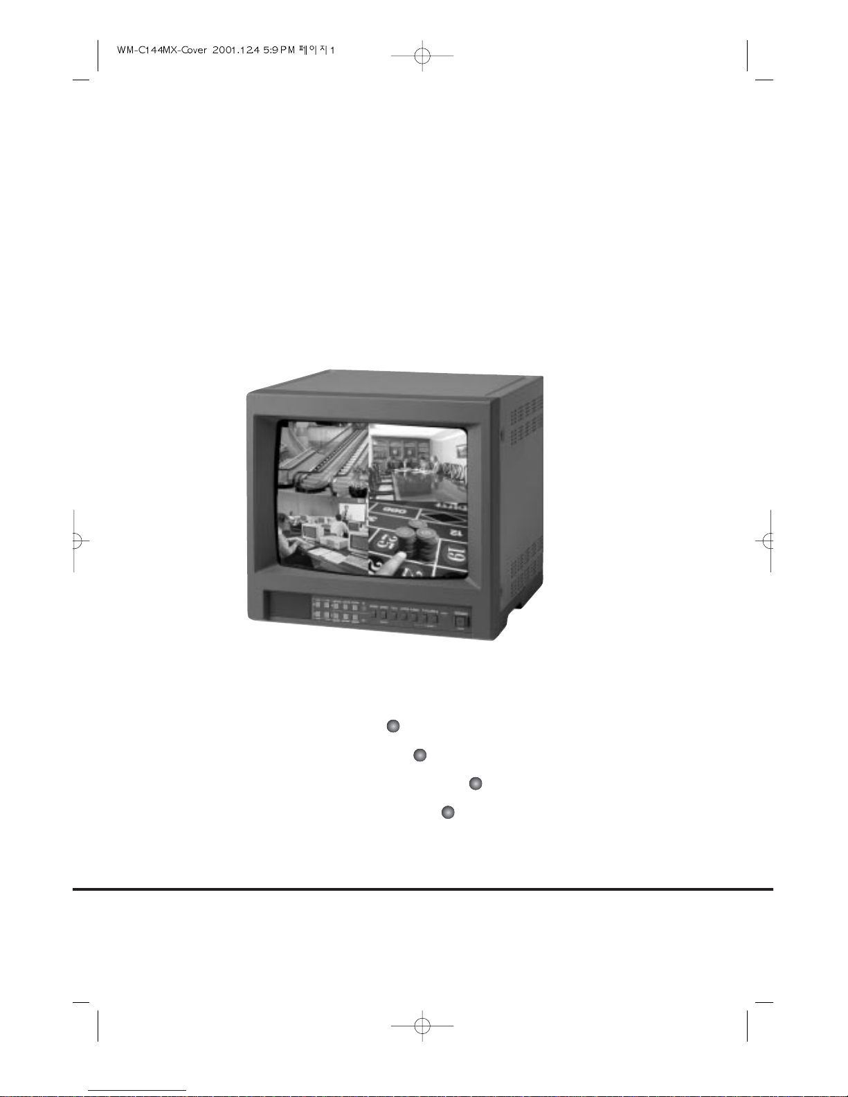
14” COLOR OBSERVATION SYSTEM
Built-in Duplex Multiplexer
Built-in Pan/Tilt Control
Real-Time Display
LIVE/PB Digital Zoom
SAFETY INFORMATIONS
CAUTION :TO REDUCE THE RISK OF ELECTRIC SHOCK, DO NOT REMOVE COVER,
NO USER-SERVICEABLE PARTS INSIDE. REFER SERVICING TO QUALIFIED
SERVICE PERSONNEL.
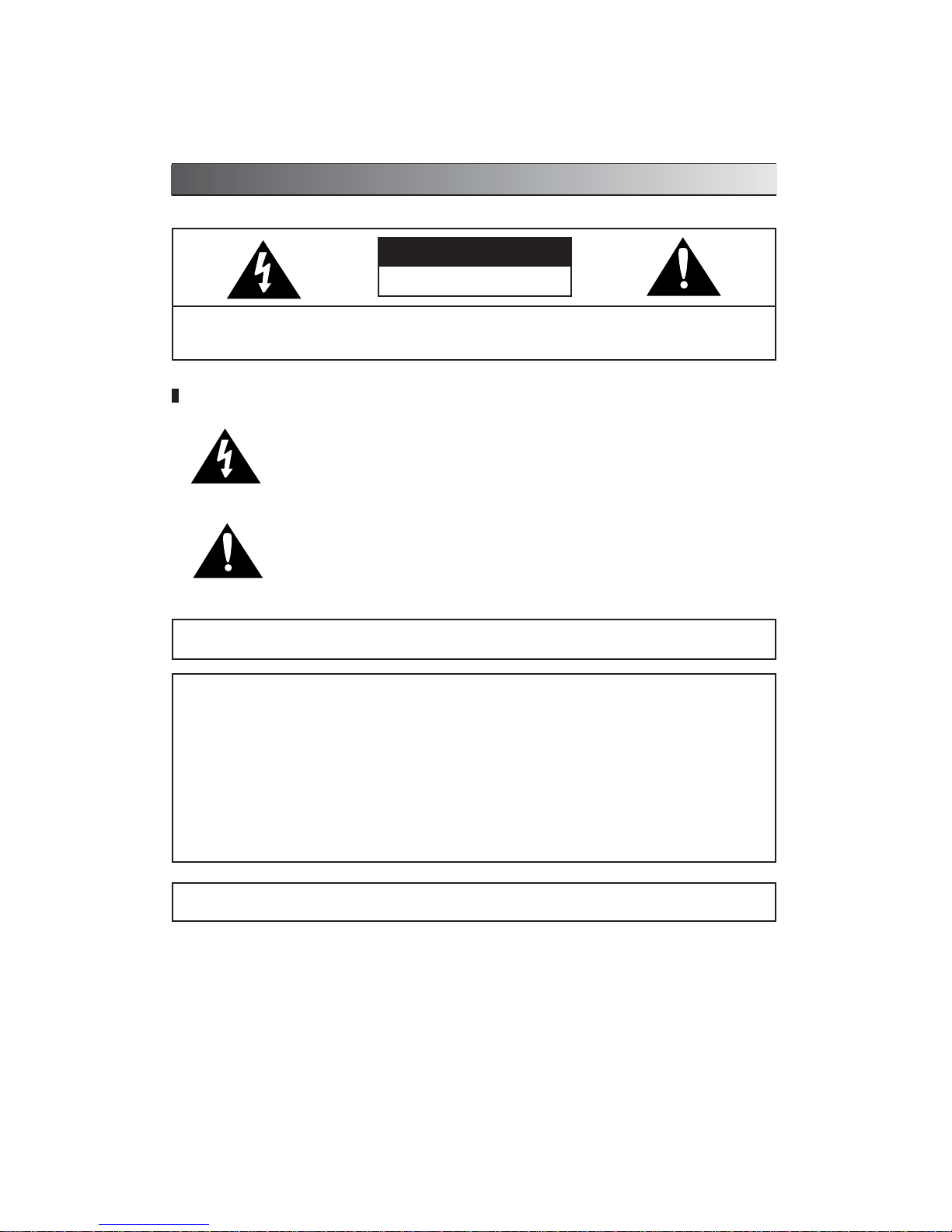
These symbols with supplemental markings are at the rear of the monitor
Explanation of Symbols
CAUTION
RISK OF ELECTRIC SHOCK
DO NOT OPEN
The lightning flash with arrowhead symbol, with an equilateral triangle, is intended
to alert the user to the presence of uninsulated "dangerous voltage" within the
product's enclosure that may be of sufficient magnitude to constitute a risk of
electric shock to persons.
The exclamation point within an equilateral triangle is intended to alert the user to
the presence of important operating and maintenance (servicing) instructions in the
literature accompanying the product.
WARNING : TO REDUCE THE RISK OF FIRE OR ELECTRIC SHOCK, DO NOT EXPOSE THIS UNIT TO
RAIN OR MOISTURE.
CAUTION : CHANGES OR MODIFICATIONS NOT EXPRESSLY APPROVED BY THE PARTY RESPONSIBLE FOR COM
PLIANCE COULD VOID THE USER’S AUTHORITY TO OPERATE THE EQUIPMENT.
NOTE : This equipment has been tested and found to comply with the limits for a Class A digital device, pursuant to part 15 of
the FCC Rules. These limits are designed to provide reasonable protection against harmful interference when the equipment is
operated in a commercial environment. This equipment generates, uses, and can radiate radio frequency energy and, if not
installed and used in accordance with the instruction manual, may cause harmful interference to radio communications.
Operation of this equipment in a residential area is likely to cause harmful interference in which case the user will be required to
correct the interference at his own expense.
The user may find the following booklet prepared by the Federal Communications Commission helpful :
HOW TO IDENTIFY AND RESOLVE RADIO-TV INTERFERENCE PROBLEMS.
This booklet is available from the US Government Printing Office, Washington, DC 20402, Stock Number004-000-00345-4

SAFETY INSTRUCTIONS
Warning! Important Safety Instructions
1) Read Instructions
All the safety and operating instructions should
be read before the appliance is operated.
2) Retain Instructions
The safety and operating instructions should be
retained for future reference.
3) Heed Warnings
All warnings on the product and in the
operating instructions should be adhered to.
4) Follow Instructions
All operating and use instructions should be
followed.
5) Cleaning
Unplug this product from the wall outlet before
cleaning. Do not use liquid cleaners or aerosol
cleaners. Use a damp cloth for cleaning the unit.
Exception: A product that is meant for
uninterrupted service and that for some
specific reason, such as the possibility of the loss
of an authorization code for a CATV converter, is
not intended to be unplugged by the user for
cleaning or any other
purpose, may exclude the reference to
unplugging the product in the cleaning
description otherwise required in 5).
6) Attachments
Do not use attachments not recommended by the
product manufacturer as they may cause
hazards.
7) Water and Moisture
Do not use this product near water,
for example near a bath tub, wash bowl, kitchen
sink, or laundry tube in a wet
basement or near a swimming pool
and the like.
8) Accessories
Do not place this product on an unstable cart,
stand, tripod, bracket or table.
The product may fall, causing serious injury to a
child or adult, and serious damage to the
product. Use only with a cart, stand,
tripod, bracket or table recommended by the
manufacturer, or sold with the product. Any
mounting of the product should follow the
manufacturer's instructions, and should use a
mounting accessory recommended by the
manufacturer.
9) An product and cart combination should be
moved with care. Quick stops, excessive force,
and uneven surfaces may cause the product and
cart combination to overturn.
10) Ventilation
Slots and openings in the cabinet are
provided for ventilation and to ensure
reliable operation of the product and to
protect it from overheating and these
openings must not be blocked or covered.
The openings should never be blocked by
placing the product on a bed, sofa, rug or other
similar surface. This product should not be
placed in a built-in installation such as a
bookcase or rack unless proper
ventilation is provided or the manufacturer's
instructions have been adhered to.
11) Power Sources
This product should be operated only from the
type of power resource indicated on the marking
label. If you are not sure of the type of power
supply to your home, consult your appliance
dealer or local power company. For products
intended to operate from
battery power or other sources, refer to the
operating instructions.
12) Grounding or Polarization
This product is equipped with a polarized
alternating-current line plug (a plug having one
blade wider than the other.) This plug will fit into
the power outlet only one way. This is a safety
feature. If you are unable to insert the plug fully
into the outlet, try
reversing the plug. If the plug should still fail to
fit, contact your electrician to replace your
obsolete outlet. Do not defeat the safety purpose
of this polarized plug.
Portable cart warning

SAFETY INSTRUCTIONS
Alternate Warnings
This product is equipped with a three-wire
grounding-type plug a plug having a third
(grounding) pin. This plug will only fit into a
grounding-type power outlet. This is a safety
feature. If you are unable to insert the plug into
the outlet, contact your electrician to replace your
obsolete outlet. Do not defeat the safety purpose
of the grounding-type plug.
13) Power-Cord Protection
Power-supply cords should be routed so that
they are not likely to be walked on or pinched by
items placed upon or against them paying
particular attention to cords at plugs,
convenience receptacles, and the point where
they exit from the product.
14) Protective Attachment Plug
The product is equipped with an attachment plug
having overload protection. This is a safety
feature. See instruction Manual for replacement
or resetting of protective device. If replacement of
the plug is required, be sure the service
technician has used a replacement plug specified
by the manufacturer that has the same overload
protection as the original plug.
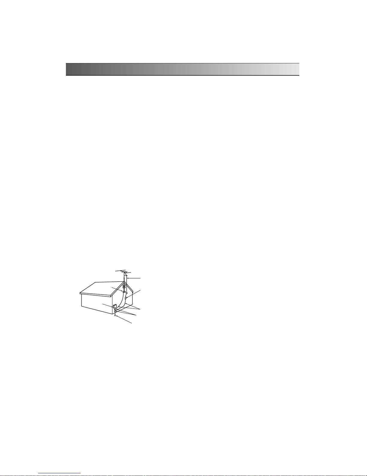
15) Outdoor Antenna Grounding
If an outside antenna or cable system is
connected to the product, be sure the
antenna or cable system is grounded so as to
provide some protection against voltage surges
and built-up static charges. Article 810 of the
National Electrical Code. ANSI/NFPA 70,
provides information with regard to proper
grounding of the mast and supporting structure,
grounding of the
lead-in wire to an antenna discharge unit, size of
grounding conductors, location of antennadischarge unit, connection to grounding
electrodes, and requirements for the grounding
electrodes. See Figure 1-1.
16) Lightning
For added protection for this product during a
lightning storm, or when it is left
unattended and unused for long periods of time,
unplug the product from the wall outlet and
disconnect the antenna or cable
system. This will prevent damage to the product
due to lightning and power line surges.
17) Power Lines
An outside antenna should not be located in the
vicinity of overhead power lines or other electric
light or power circuits, or where it can fall into
such power lines or circuits. When installing an
outside antenna system, extreme care should be
taken to keep from touching such power lines or
circuits as
contact with them may be fatal.
18) Overloading
Do not overload wall outlets, extension cords, or
integral convenience receptacles as this can
result in a risk of fire or electric shock.
19) Object and Liquid Entry
Never push objects of any kind into this
product through openings as they may touch
dangerous voltage points or short out parts that
could result in a fire or electric shock. Never spill
liquid of any kind on the receiver.
20) Servicing
Do not attempt to service this product
yourself as opening or removing covers may
expose you to dangerous volt-age or other
hazzards. Refer all servicing to qualified service
personnel.
21) Damage Requiring Service
Unplug the product from the wall outlet and refer
service opening to qualified service
personnel under the following conditions:
a)when the power-supply cord or plug is
damaged,
b)if liquid has been spilled, or objects have fallen
into the product,
c)if the product has been exposed to rain or
water.
d)if the product does not operate normally by
following the operating instructions. Adjust only
the controls that are covered by the operating
instructions as an improper adjustment of other
controls may result in dam-age and will often
require extensive work by a qualified technician
to restore the video product to its nor-mal
operation.
e)If the product has been dropped or
damaged in any way, and
f)When the product exhibits a distinct change in
performance - this indicates a need for service.
SAFETY INSTRUCTIONS
22) Replacement Parts
When replacements parts are required, be sure
the service technician has used replacements
parts specified by the
manufacturer or have the same
characteristics as the original part. Unauthorized
substitutions may results in fire, electric shock or
other hazards.
23) Safety Check
Upon completion of any service or repairs to this
receiver, ask the service technician to perform
safety checks to determine that the product is in
proper operating condition.
24) Wall or Ceiling Mounting
The product should be mounted to a wall or
ceiling only as recommended by the
manufacturer.
25) Heat
The product should be situated away from heat
sources such as radiators, heat
registers, stoves, or other products
(including amplifiers) that produce heat.
ANTENNA
LEAD IN WIRE
ANTENNA
DISCHARGE UNIT
(NEC SECTION 810-20)
GROUNDING
CONDUCTORS
(NEC SECTION 810-21)
GROUND CLAMPS
POWER SERVICE GROUNDING
ELECTRODE SYSTEM
(NEC ART 250, PART H)
GROUND CLAMP
ELECTRIC
SERVICE
EQUIPMENT
NEC NATIONAL ELECTRICAL CODE
S2898A
EXAMPLE OF
ANTENNA GROUNDING
Figure 1-1
Antenna grounding as per
National Electrical Code, ANSI/NFPA70

V
CONTENTS
INTRODUCTION ................................................................................................................................... 1
MONITOR SYSTEM PART NAME
FRONT PANEL ............................................................................................................................... 2
BACK PANEL .................................................................................................................................. 3
MULTIPLEXER SYSTEM OPERATION
STARTING THE SETUP MODE ..................................................................................................... 4
MAIN MENU ................................................................................................................................... 4
SUB MENU SETTING .................................................................................................................... 5
CAMERA INPUT ............................................................................................................................. 5
CHANNEL TITlE ............................................................................................................................. 5
DATE / TIME ................................................................................................................................... 6
AUTO SWITCH ............................................................................................................................... 6
REC TYPE ...................................................................................................................................... 7
ALARM/LOSS ................................................................................................................................. 7
ALARM/LOSS LIST ......................................................................................................................... 8
OBSERVATION CAMERA OPERATION
CAMERA PART ............................................................................................................................... 9
CAMERA INSTALLATION ............................................................................................................... 9
PAN/TILT DOME CAMERA OPERATION
CAMERA PART ............................................................................................................................. 10
CAMERA INSTALLATION .............................................................................................................10
REMOTE CONTROL UNIT ........................................................................................................... 11~12
SYSTEM OPERATION
STANDARD CAMERA OPERATION ............................................................................................ 13
MULTIPLE STANDARD CAMERA OPERATION .......................................................................... 13
OBSERVATION CAMERA TWO WAY INTERCOM INSTALLATION ............................................ 14
OBSERVATION CAMERA ALARM DEVICE INSTALLATION ...................................................... 14
PAN/TILT DOME CAMERA OPERATION ..................................................................................... 15
MULTIPLE PAN/TILT DOME CAMERA OPERATION .................................................................. 15
MULTIPLE SYSTEM OPERATION ............................................................................................... 16
BNC CAMERA SYSTEM OPERATION ........................................................................................ 16
AUXILIARY OPERATION
INSTALLATION ............................................................................................................................. 17
VCR OPERATION .................................................................................................................. 17~18
ALARM OPERATION .............................................................................................................. 19~21
VIDEO LOSS ................................................................................................................................ 21
SPECIFICATION
14” BUILT-IN MUX COLOR MONITOR ........................................................................................ 22
MULTIPLEXER ............................................................................................................................. 23
CAMERA (PAN/TILT DOME COLOR CAMERA) .......................................................................... 24
CAMERA (OBSERVATION COLOR CAMERA) ............................................................................ 25
ACCESSORIES .................................................................................................................................. 26
USER’S GUIDE ............................................................................................................................. 27~28
TROUBLE SHOOTING GUIDE .......................................................................................................... 29

VI
PRIOR TO USE
PRIOR TO USE
This is the basic manual for Built-in Mux Control 14” Color Observation System user. The content
of this manual is focused on product introduction, installing method, connecting method with other
devices, using method of various functional buttons, and system setting method with the setup
menu.
Before using this equipment, this manual should be read not only by first users, but also by the
users who are already familiar with this system or any other similar device in accordance with the
precautions stated within the manual.
Before getting started with this equipment, it should be emphasized that the user must
consult and receive help from the dealer where the product was purchased when opening the case
and fixing the internal parts of the system for upgrade or repair.
And also if you have any further questions related to using this equipment or think you have a
problem with the product, please consult your dealer.
Upon purchase of this system, unpack the box and put the unit on a floor stand, or place the unit
where you are going to install the system. Please check the contents of the package as listed below.
IN CASE of Observation system
• Monitor main unit
• Observation Camera (or Pan/Tilt Dome Camera)
• 20m(60ft) Multi(Din or RJ-11) Cable
• Instruction Manual
• Power Cable
• Remote Controller (Optional)
IN CASE of Only Monitor
• Monitor main unit
• Instruction Manual
• Power Cable
UNPACKING

1
INTRODUCTION
1
This equipment will give you added security and comfort for many years. It is easy to install in almost anywhere you
need audio/video surveillance. To safely use all the high technical functions of the unit, please read the installation
and operating instruction in manual, and keep it for the future reference. Also, it can directly control Pan/Tilt Dome
Camera without any extra controller.
FUNCTIONS
• Built-in Real Time 4 channel Color Duplex Multiplexer
• Built-in Auto Switcher
• Built-In Digital Multi Comb Filter (NTSC/PAL)
• Built-In Pan/Tilt Dome Camera Control (Multi <Din, RJ> Jack)
• Built-In Camera Vertical GEN-Lock (Multi <Din, RJ> Jack)
• Multi System (NTSC/PAL)
• Alarm In/Out & Two Way Talk
• Horizontal Resolution 420TV Lines
• Free Voltage (AC 100V ~ 240V, 50/60Hz)
• On Screen Menu Control & Digital Picture Menu Control
22
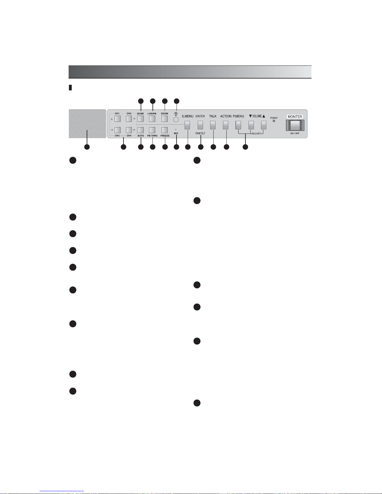
MONITOR SYSTEM PART NAME
CHANNEL SELECT BUTTONS
- In Live / PB mode : When desired channel button is
pressed, a full screen of the channel is displayed.
- Menu(S.MENU) mode
Button : To move throughout each item of the Main
Menu or that of the sub menu to set it up.
Button : To increase or decrease the value of each
item.
- Pan/Tilt Dome Camera Control
QUAD
Quad Screen display in LIVE or PB.
AUTO
Sequentially switching the channel in only LIVE MODE
LIVE/PB
Switching the LIVE Mode or Play Back Mode.
PB THRU
Monitoring the recorded multiplexer OUT signal or
Playback signal of TIME LAPSE VCR.
ZOOM
Zooming the special part of the screen in 2 Times,
pressing the button again, the screen will be larger 2
Times, and then move the highlighted area by using the
arrow buttons (,,,).
FREEZE
When a Full screen in selected and user presses the
“FREEZE” button, the screen will be frozen, and the
alphabet “F” will be displayed on to the selected channel.
If user presses the button once more, the Freeze will be
deactivated. When a Quad screen is selected, if a user
presses the “FREEZE” button and desired channel button,
then the selected channel screen will be frozen.
IR RECEIVER
Receiving the remocon signal.
MIC
MIC input when pressed only TAlK button in the channel
selected.
S.MENU(SYSTEM MENU)
If user presses this button, it will display the setup menu.
User can change the various functional settings of this
system from the setup menu. Use the arrow buttons(
) to move from menu to menu, or change the value of
the sub menu.
ENTER / PAN/TILT
• Menu(system set-up) mode : When the modification of
each Sub Menu item is complete, press this button to
save the settings. Use this button to enter a Sub Menu of
the Main Menu or to return to the Main Menu from Sub
Menu by pressing this button on “EXIT”
• Pan/Tilt On/Off button. Assuming that Pan/Tilt dome
camera is connected to any channel, if user selects the
channel and presses this button, the Pan/Tilt control mode
will be started. And using the arrow buttons (
), user
can freely control the Pan/Tilt dome camera to its taste.
(If a user uses more than two Pan/Tilt dome camera, each
pressing the Pan/Tilt button will select from CH1 to CH4,
to control the each camera.)
TALK
Press and hold this button to talk through to the camera
and release it to receive.
ACTION
This button can lock or release the door open, or activate
other alarm device. It will be used to remotely open a
door, or activate different kinds of detectors.
(Send only trigger signal)
P. MENU (PICTURE MENU)
• Each pressing this button in VCR and Live mode, the
Sub Menu will sequentially displayed on to the screen.
Use volume buttons(
) to adjust each Sub menu and
press P. Menu button to deactivate.
• Contrast : Use to adjust the contrast of the screen.
• Brightness : Use to adjust the brightness of the screen.
• Color : Use to adjust the density of color.
• Tint : Use to adjust the tint of color.(NTSC only)
• Sharpness : Use to adjust the sharpness of color.
SPEAKER
Front Panel
1 10
11
12
13
14
15
2
3
4
5
6
7
8
9
1 3
2 4 6 8
5 7 9 10 12 1315 1411
3
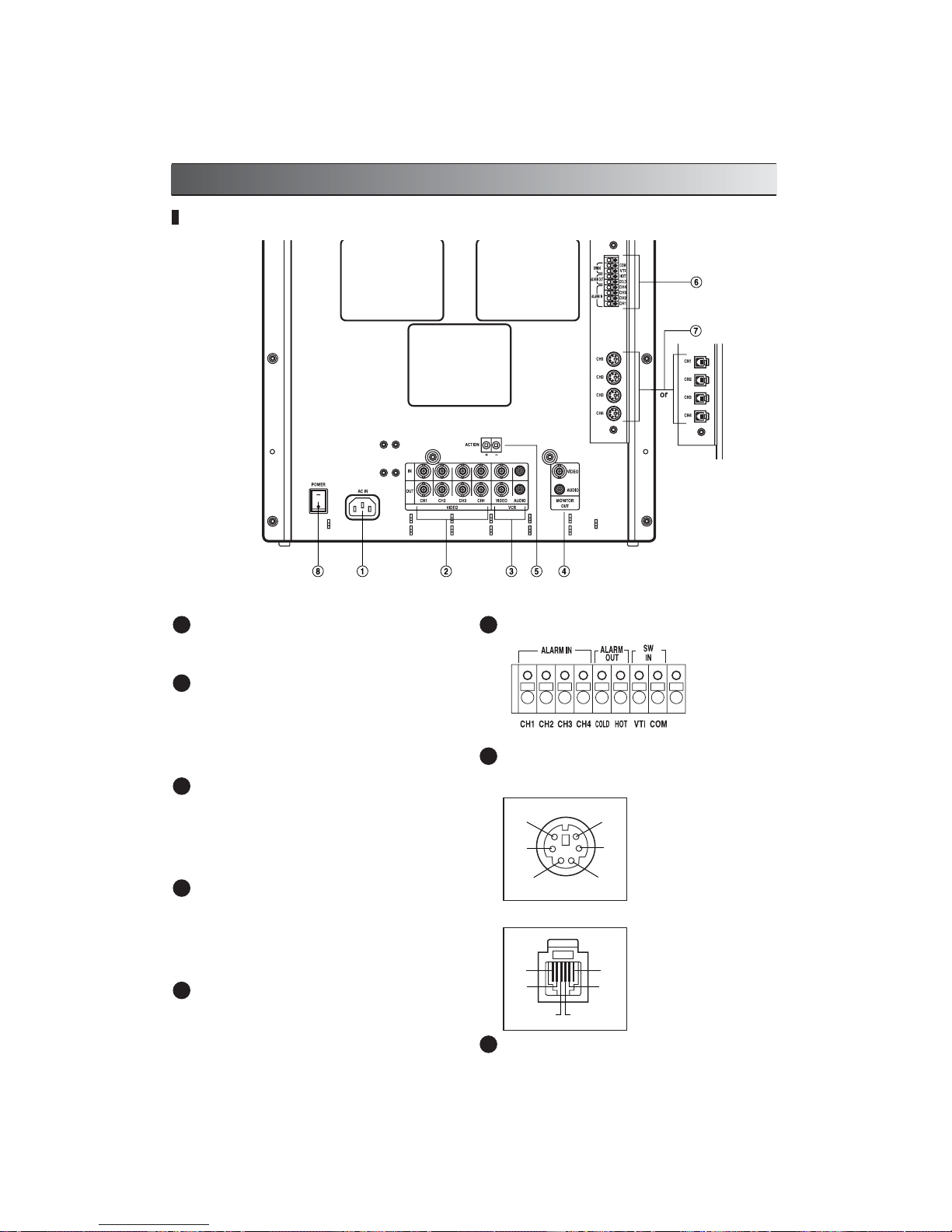
AC INPUT
This is an input terminal that connects to AC 100~240V
power.
VIDEO INPUT/OUTPUT CONNECTORS
• BNC camera inputs 1~4 : These inputs are used for
standard cameras with BNC type connectors.
• Looping outputs 1~4 : These are looping outputs for
cameras on through. It can be used to display or record
the pictures on a separate monitor or recorder.
VCR VIDEO/AUDIO INPUT/OUTPUT CONNECTORS
Video/Audio input connectors are for receiving video/audio
signal from VCR or another video unit.
Video/Audio output connectors are for transmitting
video/audio signal from a camera to another monitor.
Also used in recording on VCR.
MONITOR VIDEO/AUDIO OUTPUT CONNECTORS
Video/Audio output for slave monitor. Connect via double
male to double male RCA
leads of required length.
NB : Maximum recommended distance between master
and slave monitor is 20m.
ACTION TERMINAL
To activate several kinds of detectors, such as Door Lock
and Alarm Device.
ALARM TERMINAL
CAMERA INPUT MULTI(DIN) JACKS
To connect to 4 cameras, such as our Pan/Tilt Dome
Camera and general Observation Camera.
CAMERA INPUT RJ JACKS
MAIN POWER SWITCH
MONITOR SYSTEM PART NAME
Back Panel
1
2
3
4
5
6
7
8
A) +12V
B) Audio in
C) CAPW
(Camera auto amp)
D) Video in
E) Audio out (Alarmin)
F) V-sync (Gen-lock)
D
E
F
A
B
C
D
E
F
A
B
C
A) Alarm + Gen Lock
B) B+ (DC 15V)
C) Audio out + Pan/Tilt
D) Video in
E) Audio in
F) GND
4
MULTIPLEXER SYSTEM OPERATION
This chapter shows you how to execute various modes using the system setup menu.
STARTING THE SETUP MODE
1. Check the power cables of the equipment connected to
Monitor and turn the power switch.
2. Press the S. Menu button on the front panel.
NNNNoooottttee
ee
Only while in Live Mode, you can enter the setup mode.
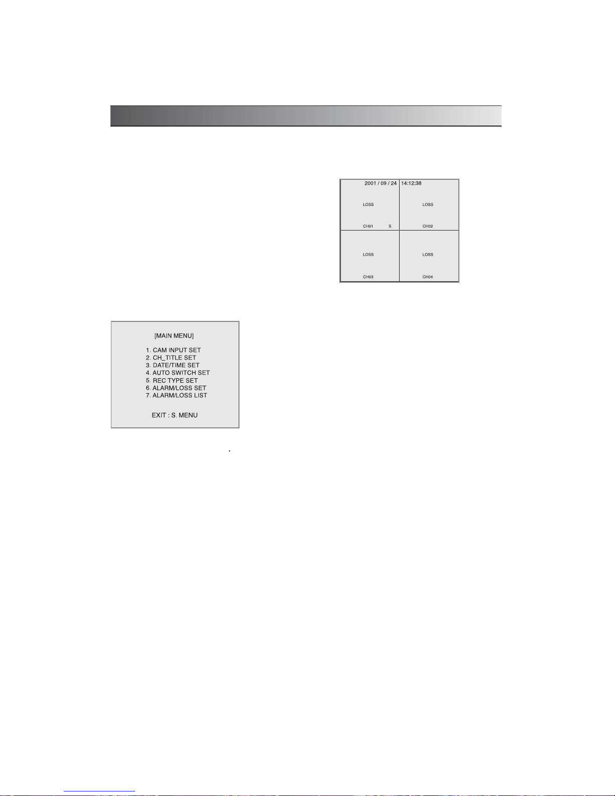
MAIN MENU
Press the “S. MENU” button on the front of the system, the main menu of the system setup appears as follows.
• Modifying settings
Select a menu item by using the
buttons and press ENTER and then you find the SUB Menu and you can
change the setup by press the direction Key (
,,,
)
• Saving the Setting / Returning to the Main Menu
When the modification of each sub menu item is complete, press the Enter button to save the settings. Use this
button to enter a Sub Menu of the Main Menu or to return to the Main Menu from Sub Menu, placed the cursor
on “EXIT”.
5
MULTIPLEXER SYSTEM OPERATION
SUB MENU SETTING
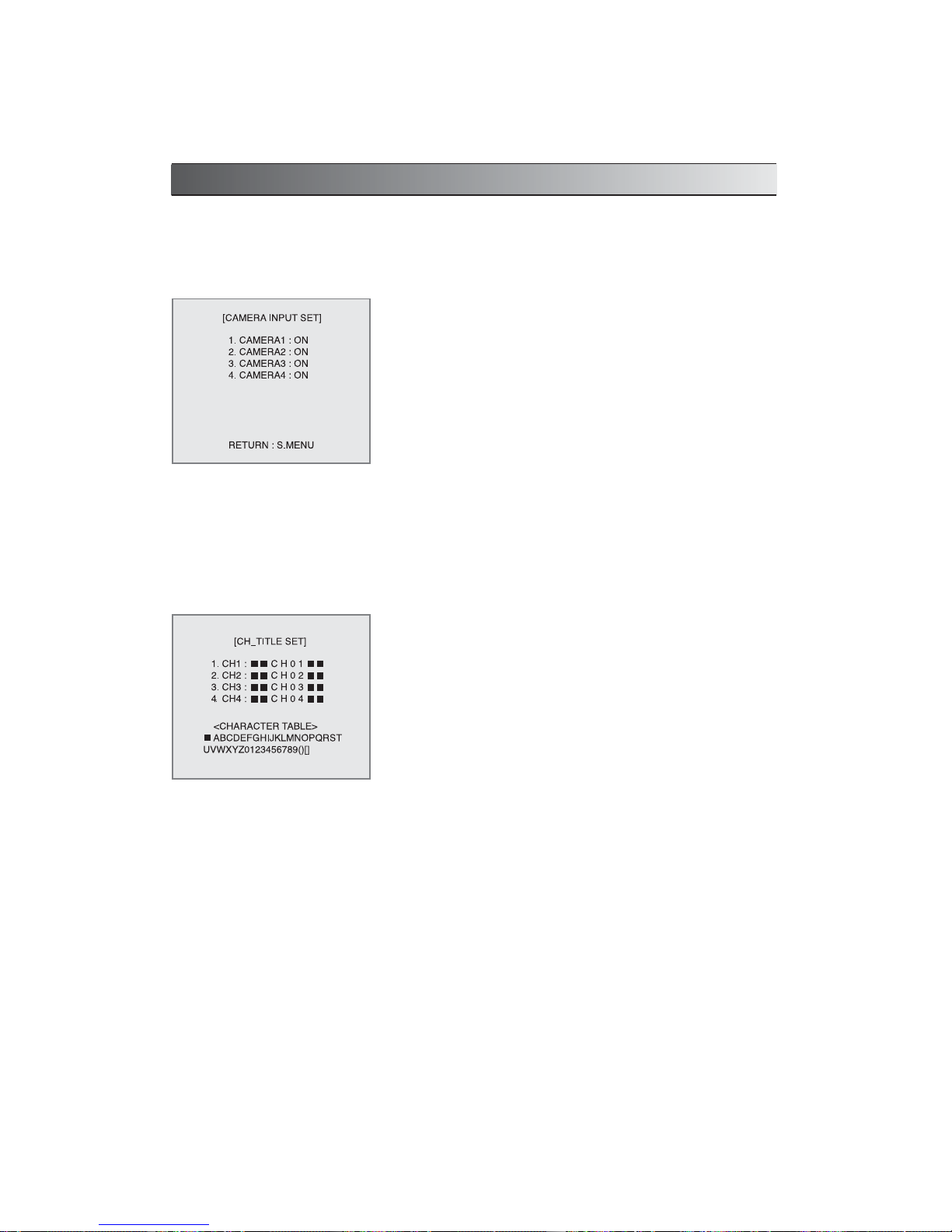
1. CAMERA INPUT SET
- Set channel [ON], if camera is connected to the channel, and set channel
[OFF] if camera is not connected to the channel.
- If the channel is set to [OFF], missing video input signals are not treated
as LOSS.
• From the <MENU>, set the cursor on the 1. CAMERA INPUT SET item
using and keys, and press ENTER key.
[CAMERA INPUT SET] screen will be displayed.
• In the screen, set the cursor on the channel to configure using
and
keys, select using or key, and set the channel status ON or
OFF using
and keys.
Pressing the S MENU key takes the user to the previous menu
(<MENU>).
2. CHANNEL TITLE
- Enter the title of each channel.
• In <MENU>, set the cursor on the 2.CH_TITLE SET item using
and
keys, then press ENTER key. [CH_TITLE] screen appears.
• Use
and keys to select, use and keys to move and select
desired alphabet, and select the alphabet from the character table using
and keys.
 Loading...