

Page 1
SERVICE & PARTS MANUAL
Models:
4200 ELECTRIC COMPACT CONVECTION OVEN
4200
4292
35 Garvey Street, Everett, MA 02149
Tel. (617) 387-4100, Telex 94-9414, Cable MAFORCO
Facsimile # 617-387-4456
Form Number S-2296B 7/84 Printed in U.S.A.
Page 2

TABLE OF CONTENTS
4.2.7
Motor Removal
4-2
Electrical Data
60
Hz
2-4
5.2
Trouble
-
Shooting Guide
5-1
SECTION 1 INTRODUCTION
1.1 Description 1-1
1.2 Oven Components 1-1
1.3 Basic Functioning 1-1
1.4 Service 1-1
4.2.3 Oven Liner Gasket Removal 4-1
4.2.4 Gasket Replacement 4-1
4.2.5 Blower Wheel Removal 4-1
4.2.6 Blower Wheel Replacement 4-1
SECTION 2 INSTALLATION
2.1 Receiving 2-1
2.2 Assembly 2-1
2.2.1 Vent Box Attachment 2-1
2.2.2 Single Oven on 4"' 102mm Legs 2-1
2.2.3 Single Oven on 27" 686mm Legs
with shelf 2-1
2.2.4 Stacked Ovens on 18" 457mm Legs
with shelf 2-2
2.3 Electrical Connection 2-2
2.4 Oven Checkout and Adjustments 2-3
2.4.1 Door Adjustment 2-3
2.4.2 Thermostat Calibration 2-3
2.4.3 To Calibrate Electronic Thermostat 2-3
Wiring Diagram, Schematic and
Wiring Diagram, Schematic and
Electrical Data 50 Hz
SECTION 3 OPERATION
3.1 Principle of Operation 3-1
3.2 Controls 3-1
3.3 Preheating 3-1
3.4 Operation 3-1
SECTION 4 MAINTENANCE
4.1 Cleaning 4-1
4.2 Removal & Replaceme nt of Parts 4-1
4.2.1 Door Removal 4-1
4.2.2 Door Replacement
2-5
4-1
4.2.8 Motor Replacement 4-2
4.2.9 Switch Removal 4-2
4.2.10 Switch Replacement 4-2
4.2.11 Contactor and Fuse Holder
Removal 4-2
4.2.12 Contactor and Fuse Holder
Replacement 4-2
4.2.13 Thermostat Removal 4-2
4.2.14 Thermostat Replacement 4-3
4.2.15 Heater Element Removal 4-3
4.2.16 Heater Element Replacement 4-3
4.2.17 Door Interlock Switch Bracket
Removal 4-3
4.2.18 Door Interlock Switch Bracket
Replacement 4-3
SECTION 5 TROUBLE-SHOOTING
5.1 General
Table 5-1 Trouble Shooting Guide 5-1
Table 5-2 Electrical Fault Isolation 5-2
5.3 Wiring 5-2
Table 5-3 Trouble-Shooting Guide For
Electronic Thermostat 5-3
SECTION 6 ILLUSTRATED PARTS LIST
6.1 General 6-1
6.2 Ordering Information 6-1
Illustrated Parts List 6-2 to 6-7
5-1
Page 3

4200 Compact Convection Oven
SECTION 1 INTRODUCTION
This service and parts manual contains general information, installation, operation, principles of operation,
trouble-shooting and maintenance information for the Market Forge Model 4200 Electric Compact Convection
Oven. Also included are parts lists, in which each replaceable part is identified and shown in an accompanying
1.1 DESCRIPTION
The Market Forge Model 4200 Electric Compact
Convection Oven is an electrically powered
convection oven designed to achieve high-volume
cooking with a minimum of power consumption. The
unit consists of a heavily insulated cooking
compartment fitted with a two-speed convector
blower and heated by electric elements. All oven
controls are located on a panel on the right front of
the oven as seen from the front.
1.2 OVEN COMPONENTS
The major assemblies of the model 4200 are the
stainless steel and flat black painted steel cabinet
enclosure, door with window, porcelain cooking
compartment with nine-position shelf supports,
heating element and contactor assembly, and control
panel assembly. Controls and indicators include the
thermostat, main power switch, blower speed switch,
cool down switch, elements on indicator light, 60minute timer, and two 15 amp fuses. The oven is
available in variety of mounting configurations: 4"
102mm high legs, 27" 686mm legs with shelf, or
stacked on top of another Model 4200 with the
bottom unit on 18" 457mm stainless steel legs with
shelf.
1.3 BASIC FUNCTIONING
The Model 4200 becomes operational when the
power switch is placed in the ON position, door is
1-1
illustration.
closed, and thermostat set. Contactors located in the
control section close the circuit to heating elements
located at the right of the cooking chamber. When
the chamber reaches the preset temperature, the
thermostat contacts open, causing the contactors to
interrupt the circuit to the heating elements. When
the temperature in the chamber drops enough to
close the thermostat contacts, the circuit closes
again. Any number of such cycles might occur
during the cooking time, indicated by the element
indicator light coming on and off.
1.4 SERVICE
Required service, both preventive and corrective, is
explained in section 5. Should repairs be required, a
network of authorized agencies is available to assist
with prompt service. A current directory of
Authorized Service Agencies may be obtained by
contacting:
Product Service Department
Market Forge Company
35 Garvey Street
Everett, MA 02149
(617) 387-4100
The model and serial number must be referenced
when corresponding with Market Forge.The data
plate with serial number is located on the right of the
bottom front trim ledge.
Page 4

ONE YEAR WARRANTY
We warrant that Market Forge cooking equipment will be free from defects in material and factory workmanship for
a period of one year from the EFFECTIVE WARRANTY DATE, which shall be the date the equipment is placed in
service or 15 months from date of shipment from our factory, whichever comes first Providing the equipment is
unaltered, has been properly installed, maintained and operated, we will repair, or replace, at our option, FOB
Everett, Massachusetts, that part of any such equipment that becomes defective due to defects in material and/or
factory workmanship during the applicable warranty period, subject to the following limitations
Market Forge will replace, repair, or adjust at no cost any part of all equipment other than portable equipment,
which becomes defective due to material or factory workmanship within ninety (90) days of the Effective Warranty
Date Any labor required for any such repair, replacement or adjustment after ninety (90) days shall be paid by the
user or dealer, unless our extended labor warranty contract has also been purchased to cover this particular
equipment
With respect to PORTABLE COOKING EQUIPMENT, so designated in this price list, Market Forge will replace,
repair, or adjust at no cost any part which bec omes defective due to material or factory workmanship within one (1)
year of the Effective Warranty Date. providing the portable equipment is taken or shipped to the closest authorized
service agency, transportation charges prepaid Proof of purchase shall be provided upon request of the service
representative
With respect to STEAM BOILER SHELLS only. there is an additional four (4) year warranty limited to the
replacement of such shells Whenever we replace a steam boiler shell after one (1) year from the Effective
Warranty Date, the user shall pay a pro-rata share of the then selling price therof based on the number of months
elapsed from the Effective Warranty Date
THIS WARRANTY IS LIMITED TO COOKING EQUIPMENT INSTALLED WITHIN THE 48 CONTINENTAL
UNITED STATES AND CANADA IN ALASKA, HAWAII, AND ELSEWHERE OUTSIDE CONTINENTAL US AND
CANADA, THIS WARRANTY IS LIMITED TO THE REPLACEMENT OF PARTS ONLY
THERE ARE NO WARRANTIES, EXPRESSED OR IMPLIED, MADE BY MARKET FORGE FOR ITS COOKING
EQUIPMENT. EXCEPT THIS WARRANTY, WHICH IS EXPRESSLY IN LIEU OF ANY OTHER WARRANTIES,
EXPRESSED OR IMPLIED, INCLUDING ANY IMPLIED WARRANTY OR MERCHANTABILITY OR FITNESS FOR
A PARTICULAR PURPOSE AND IN LIEU OF ALL OTHER OBLIGATIONS OR LIABILITY ON THE PART OF
MARKET FORGE. INCLUDING LIABILITY FOR INCIDENTAL OR CONSEQUENTIAL DAMAGES OR FOR LOSS
OF PROFITS OR GOODWILL. NO OTHER WARRANTIES ARE AUTHORIZED ON BEHALF OF MARKET
FORGE MARKET FORGE. COOKING EQUIPMENT IS NOT DESIGNED FOR PERSONAL, FAMILY OR
HOUSEHOLD PURPOSES AND ITS SALE FOR SUCH PURPOSES IS NOT INTENDED, BUT IN THE EVENT
THAT OUR COOKING EQUIPMENT IS SO USED. THEN THIS WARRANTY SHALL NOT APPLY AND THE
EQUIPMENT SHALL BE SOLD AS IS, WITHOUT WARRANTY OF ANY KIND, EXPRESS OR IMPLIED,
INCLUDING ANY WARRANTY OF MERCHANTABILITY OR FITNESS FOR A PARTICULAR PURPOSE.
EXTENDED LABOR WARRANTY AND MECHANICAL START-UP
The very great majority of all warranty service problems become apparent within the first 90 days of use However,
some people prefer to have labor coverage as well as replacement parts coverage beyond that period. This
Extended Labor Warranty is available at extra cost in Continental U S and Canada which provides an additional
nine months labor coverage following the standard three month labor coverage from the effective warranty date.
The cost of this Extended Labor Warranty is 2% of the cost of the equipment covered.
If the Extended Labor Warranty was purchased by your dealer to cover your equipment, then we provided the
dealer with written acknowledgement of it when we delivered the equipment. He was, in turn, to give you a copy of
this Extended Labor Warranty form When service is performed, please show this to the service mechanic to avoid
confusion Extended Labor Warranty has also been recorded at our factory.
Providing the Extended Labor Warranty has been purchased, and subject to availability of the local authorized
factory service agency, a mechanical start-up to insure that the equipment has been properly installed and is
operating properly can be purchased for an additional 2% of the cost of the equipment
Page 5
SECTION 2 INSTALLATION
Figure
2-2
Table
2-1
2.1 RECEIVING
1. Examine shipment for external and internal
damage and completeness. Transport crated
oven through building, to installation area before
unpacking.
2. Report any damage or shortages to carrier and
Market Forge immediately.
3. DO NOT AT ANY TIME LAY THE OVEN DOWN
ON ITS TOP, RIGHT SIDE, OR FRONT. TO
DO SO MAY DAMAGE THE EQUIPMENT AND
VOID THE WARRANTY.
2.2 ASSEMBLY
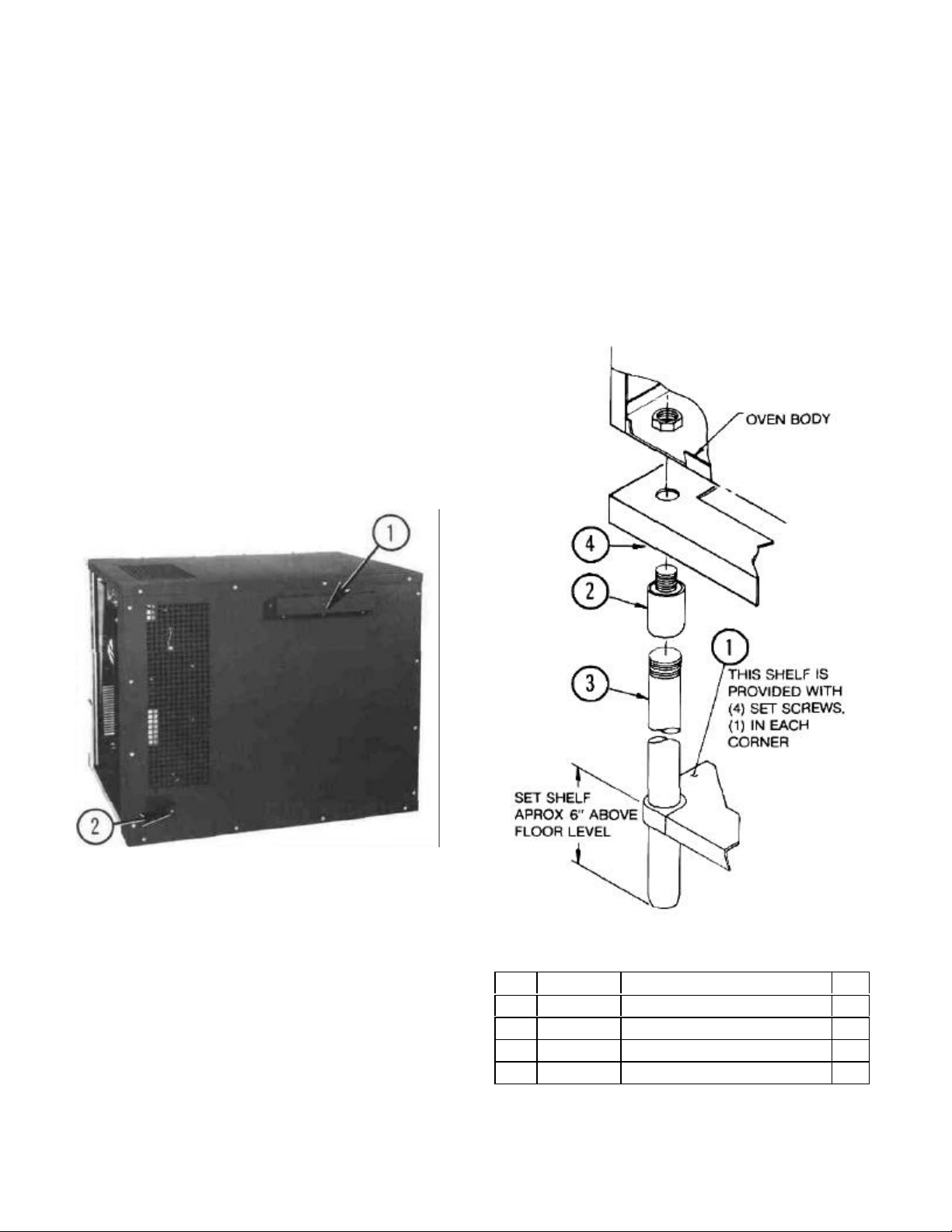
2.2.1 Vent Box Attachment
1. Remove steam vent box and packet of screws
from inside oven and attach vent box to back of
oven over vent opening using five #8 sheet metal
screws. (Fig. 2-1 No. 1)
3. Insert leg tops (Fig. 2-2 No. 2) through holes in
angle iron frame (Fig. 2-2 No. 4) into weldnuts in
bottom of oven.
4. Screw leg tops (Fig. 2-2 No. 2) into weldnuts by
turning leg and top assemblies.
5. Raise shelf (Fig. 2-2 No. 1) to desired height and
tighten set screws in shelf corners.
Figure 2-1
2.2.2 Single Oven on 4" (102mm) Legs
Fasten legs to the weld nuts located on bottom panel
of oven. The hex foot on the leg is adjustable.
2.2.3 Single Oven on 27" (686mm) Legs with Shelf
1. Insert legs (Fig. 2-2 No. 3) through holes in shelf
(Fig. 2-2 No. 1). Do not tighten set screws in
corners of shelf.
2. Screw leg tops (Fig. 2-2 No. 2) onto legs (Fig. 22 No. 3).
Item Part No. Description Qty.
1 99-6180 Solid Shelf, ST. ST. 1
2 A10-0635 Leg Top 4
3 A10-0634 Floor Leg, 27" High 4
4 D99-6183 Shelf, 4200 Elec. Oven 1
Page 6
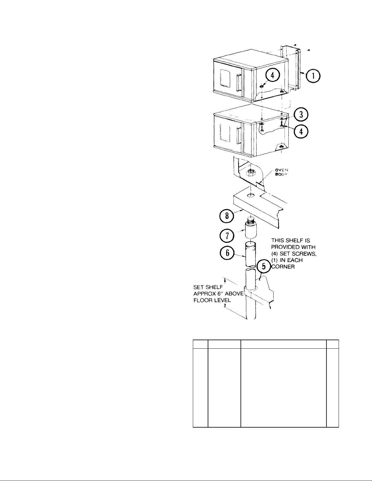
2.2.4 Stacked Ovens on 18" (457mm) Legs with
Shelf
1. Insert legs (Fig. 2-3 No. 6) through holes in shelf
(Fig. 2-3 No. 5). Do not tighten set screws in
corners of shelf.
2. Screw leg tops (Fig. 2-3 No. 7) onto legs (Fig. 2-3
No. 6).
3. Insert leg tops (Fig. 2-3 No. 7) through holes in
angle iron frame (Fig. 2-3 No. 8) into weldnuts in
bottom of oven.
4. Screw leg tops (Fig. 2-3 No. 7) into weldnuts by
turning leg and leg top assemblies.
5. Raise shelf (Fig. 2-3 No. 5) to desired height and
tighten set screws in shelf corners.
6. Remove access panel from right side of both
ovens.
7. Remove knockouts from the top of the bottom
oven and from the bottom of the top oven.
8. Place upper oven on top of lower oven and line up
the holes in the top of the lower oven with the
holes in the bottom of the upper oven.
9. Fasten ovens together with the washer (Fig. 2-3
No. 3) and bolt (Fig. 2-3 No. 2) inserted up thru top
of lower oven into bottom of upper oven using the
existing weld nut to fasten the rear and the nut
provided with the stacking kit (Fig. 2-3 No. 4) to
fasten the front.
10. Remove the existing vent covers from each oven
and replace with the vent riser (Fig. 2-3 No. 1)
using the fasteners just removed.
2.3 ELECTRICAL CONNECTION
1. Read data plate located on top surface of right side
of bottom trim just below control panel before
connecting electrical supply to oven. Make sure
electrical supply is the same voltage, phase, and
frequency called for on data plate.
2. All ovens are shipped 3 phase and may be
converted to single phase as per alternate 1 phase
wiring diagram.
3. Feed supply through opening in rear of oven (Fig.
2-1 No. 2) and connect supply wires to terminal
block behind control panel.
4. Wiring diagram label is located on control
bracket, accessible by opening control
panel.
NOTE: Improper connection to power supply or
connection to power supply other than that designated
on data plate will void the warranty.
Figure 2-3
Item Part No. Description Qty.
1 C99-6178 Vent Riser 1
2 10-2564
3 10-2411 Plain Washer, 3/4 2
4 10-2320
5 99-6180 Solid Shelf, ST. ST. (Ref. Dwg.
6 A09-5271 Floor Leg, 18" High 4
7 A10-0635 Leg Top 4
8 D99-6183 Shelf, 4200 Elec. Oven 1
Hex Bolt, 3/4-10 x 3" Long
Hex Nut, 3/4-10
C25-2624) 1
Table 2-2
2
1
Page 7
2.4 OVEN CHECKOUT AND ADJUSTMENTS
2.4.1 Door Adjustment
The door was properly adjusted at the factory, if door
does not open or close properly adjust the ball plunger
catch as follows:
1. Remove adjusting wrench from back of manual
and insert in notches on sides of ball plunger.
2. Loosen jam nut with wrench.
3. Turn adjusting wrench left or right until ball
plunger engages in door striker plate for best
operation.
4. Tighten jam nut with wrench while adjusting
wrench is still engaged in notches.
5. Return adjusting wrench to back of manual.
2.4.2 Thermostat Calibration
The thermostat is a device which automatically limits
heat input at or below the dial setting.
Before attempting to calibrate thermostat, make sure
that the thermostat is the cause of problems
experienced. Check for improper electrical service,
incorrect mixes over and under proofing, incorrect
temperatures, and warping pans.
Thermostats are calibrated and sealed by the original
manufacturer before leaving their plant. Only a
qualified service person should make calibration
adjustments, if they become necessary.
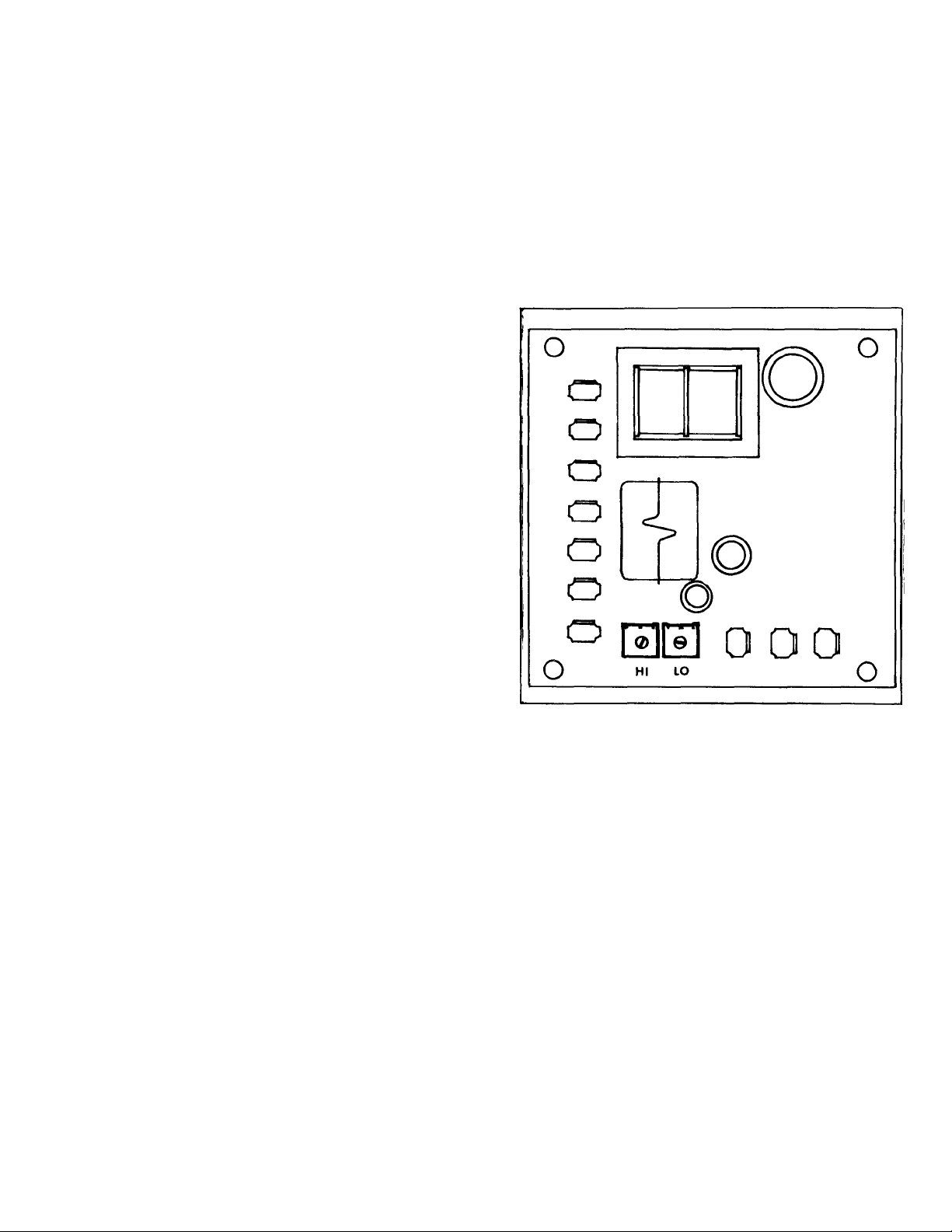
2.4.3 To Calibrate Electronic Thermostat
1. Set oven thermostat knob at 350° F.
2. Allow oven to preheat to 350° F.
3. Observe temperature with digital thermometer.
4. If temperature goes above 350° F turn setpot labelled
HI (on circuit board) counter clockwise. 1/4 turn
should be sufficient.
5. Allow time for oven temperature to drop, then
recheck temperature.
6. If temperature is below 350° F turn setpot labelled HI
(on circuit board) clockwise. 1/4 turn should be
sufficient.
7. Repeat steps 4 to 7 until oven temperature stabilizes
at 350° +5°F.
8. Apply Glyptol or Duco Cement to setpot to prevent
rotation.
Figure 2-4
Page 8

Page 9

Page 10

SECTION 3 OPERATION
3-1 PRINCIPLES OF OPERATION
Uniform distribution of heat within the oven is assured
by continuous operation of a convector blower.
Moving air continuously strips away a thin layer of
moisture and cold air from the top of the food allowing
more rapid heat penetration. Lower temperatures and
shorter times than those used in conventional deck
ovens can be used.
In general, temperature settings can be reduced by
50° F 28° C from recipe temperatures for conventional
ovens. Some products may require slightly higher or
lower temperatures.
Product should be checked for doneness in about half
the time it would take in a conventional oven. Time
savings may be about 15% to 20%.
3.2 CONTROLS
1. All controls for the Model 4200 oven are located on
the control panel on the front of the oven (Fig. 3-
1). These controls are; a thermostat to control
oven temperature (Fig. 3-1 No. 1), an oven ready
indicator light (Fig. 3-1 No. 2), a power switch with
ON and OFF positions (Fig. 3-1 No. 3), a blower
switch with high and low positions (Fig. 3-1 No. 4),
a cool down switch with manual and auto
positions (Fig. 3-1 No. 5) and a 60-minute
mechanical timer (Fig. 3-1 No. 6).
3.3 PRE-HEATING
1. Set thermostat to desired temperature, set blower
switch to desired speed, and turn on power
switch. Blower wheel should rotate clockwise
when viewed from front of oven. Low speed is
suggested for fragile products ie those levened by
beaten egg whites such as souffles, angel food
cake and popovers.
2. Indicator light will go out when desired
temperature is reached. Oven will pre-heat to
350° F 180° C in about 10 minutes. Large
differences in time from this indicate faulty heating
element, or connection to wrong electric power
supply.
Figure 3-1
3.4 OPERATION
1. Set temperature about 50° F 28° C less than
what recipe calls for when using standard oven.
2. Load pans evenly on shelves making sure pans
don't touch sides of oven or other pans.
3. Check food for doneness in about half the time it
would take in a conventional deck oven. Visual
inspection of food can be made without opening
the door by looking through tempered glass
window.
4. Blower will automatically shut off by a door
interlock switch when door opens (Fig. 3-1 No.
7). Closing the door will restart the blower.
5. Blower may be operated with door open by
placing cool down switch in manual position. No
power is supplied to heating elements with cool
down switch in manual position, allowing rapid
lowering of oven temperatures with door open.
Page 11

SECTION 4 MAINTENANCE
4.1 CLEANING
1. Clean interior of oven with a commercially
available oven cleaner suitable for use on
porcelain.
2. Racks, rack supports, and blower wheel may be
cleaned by soaking in ammonia and water
solution after removing them from the oven.
3. Stainless steel parts may be cleaned using a
commercially available stainless steel cleaner.
4.2 REMOVAL AND REPLACEMENT OF PARTS
WARNING: Disconnect oven from main
power supply before working on oven.
4.2.1 Door Removal
1. Remove lower screw (Fig. 4-1 No. 1) from upper
hinge assembly of door.
2. Loosen top screw (Fig. 4-1 No. 2) from upper
assembly.
3. Push upper hinge pin (Fig. 4-1 No. 3) into door.
4. Rotate top of door forward to clear upper frame.
5. Pull up and out on door to remove .
4.2.4 Gasket Replacement
1. Replace top and bottom metal gaskets on front of
oven liner and screw in place.
2. Replace left and right side metal gaskets and
screw in place.
4.2.5 Blower Wheel Remover
1. Shut off main power supply.
2. Remove baffle by placing hand under back end
and rotat ing baffle up and out.
3. Loosen set screws (Fig. 4-2 No. 1) on the wheel
hub.
4. Pull blower wheel (Fig. 4-2 No. 2) off of shaft.
Figure 4-1
4.2.2 Door Replacement
Reverse above procedure being sure to put as many
washers under as there were before removal.
4.2.3 Oven Liner Gasket Removal
1. Remove all screw from gaskets.
2. Remove all gaskets.
Figure 4-2
4.2.6. Blower Wheel Replacement
1. Remove metal burrs and foreign matter from motor
shaft with emery cloth or sandpaper.
2. Lubricate blower wheel hub with high graphite
grease. (Remove blower and lubricate at least
once every six months).
3. Place blower wheel on shaft. Make sure set
screws are positioned over the flats on the shaft.
Make sure there is 3/16" 4.7mm clearance
between blower wheel and oven wall.
4. Tighten set screws to 160 in-lbs. torque (18. N-M).
Page 12

4.2.7 Motor Removal
1. Make sure main power supply is disconnected
from oven.
2. Remove baffle and blower wheel.
3. Remove right side panel.
4. Open control compartment cover.
5. Remove motor bolt access plate
(Fig. 4-3 No. 1).
6. Remove four nuts and bolts holding motor (Fig. 43 No. 2) to motor mount.
7. Remove cover from wiring box mounted on motor
and disconnect wires (Fig. 4-3 No. 3).
4.2.11 Contactor and Fuse Holder Removal
1. Make sure power supply to oven is off.
2. Open control compartment cover.
3. Disconnect wires from appropriate component.
4. Unscrew fasteners of appropriate components
and remove.
4.2.12 Contactor and Fuse Holder Replacement
1. Attach components to mounting.
2. Replace and tighten fasteners.
3. Reconnect wires.
4.2.13 Thermostat Removal
1. Make sure power supply to oven is off.
2. Open control compartment cover.
3. Remove racks and rack supports from oven
compartment.
4. Remove baffle.
5. Disconnect thermocouple lead wires (Fig.
4-4 No. 1) from circuit board.
6. Unscrew thermocouple from oven liner.
7. Pull thermocouple and wires through oven liner
into oven compartment and remove.
8. Remove circuit board (Fig. 4-4 No. 2) from
bracket.
Figure 4-3
4.2.8 Motor Replacement
1. Reverse procedure above.
2. Check motor wiring to make sure blower turns
clockwise when seen from front of oven.
4.2.9 Switch Removal
1. Make sure power supply to oven is off.
2. Open control compartment cover.
3. Disconnect wires to switch.
4. Depress spring clips on switch and push forward.
4.2.10 Switch Replacement
1. Push switch into proper control panel opening until
spring clips catch.
2. Reconnect wires to switch.
3. Close control cover.
Figure 4-4
Page 13

4.2.14 Thermostat Replacement
Follow 4.2.13 in reverse order.
4.2.15 Heater Element Removal
1. Make sure power supply to oven is off.
2. Remove right side panel.
3. Remove element terminal cover above motor
and disconnect wires.
4. Remove element plate and insulation spacer.
5. Remove racks and rack supports from oven
cavity (Fig. 4-5 No. 1).
6. Remove baffle (Fig. 4-5 No. 2)
7. Remove eight screws holding the element
assembly to the oven wall.
8. Remove elements.
4.2.16 Element Replacement
Follow 4.2.15 in reverse order.
4.2.17 Door Interlock Switch Bracket Removal
1. Make sure power supply to oven is off.
2. Open control compartment cover.
3. Remove wires to door interlock switches.
4. Remove two bracket retaining screws (Fig.
4-6 No. 1).
5. Remove interlock switch assembly (4-6
No. 2).
Figure 4-5
Figure 4-6
4.2.18 Door Interlock Switch Replacement
1. Insert long end of door activated plunger through
hole in left front side of control compartment
(Fig. 4-6 No. 3).
2. Replace spring (Fig. 4-6 No. 4) and switches
(Fig. 4-6 No. 5) in bracket and secure switch
assembly with 2 screws.
3. Position switches so that push buttons on
switches just touch actuator plate on plunger
rod.
4. Replace wires using wiring diagram as guide.
5. Replace control compartment cover.
Page 14

SECTION 5 TROUBLE-SHOOTING
c) Oven door open.
Close door
Replace as required
5.1 GENERAL
The information in this section is intended to assist
both the operator and service personnel in locating
the general source of problems which may occur with
the Model 4200 Compact Convection Oven. Before
following any of the procedures given in this section,
the operator should be thoroughly familiar with the
operating
TABLE 5-1 TROUBLE-SHOOTING GUIDE
PROBLEM
Probable Cause Remedy
1. CONVECTOR FAN FAILS TO OPERATE.
a) Power to oven is off. Locate external circuit breaker for power and
instructions and the function of all controls described
in Section 3. If the problem cannot be readily
corrected, the operator should contact the nearest
authorized Market Forge Service Agency for
assistance.
5.2 TROUBLE-SHOOTING GUIDE
A general trouble-shooting guide for use by service
personnel is given in Table 5-1.
b) ON-OFF switch off. Place in ON position
d) Faulty cool down switch ON-OFF Test each component and connecting wiring
switch, door switch, fan motor, wiring Replace as required
2. OVEN WILL NOT HEAT WITH THERMOSTAT AT MAXIMUM SETTING, (FAN OPERATING).
a) Faulty thermostat or wiring. Test thermostat and connecting wiring.
b) Thermostat contacts or coil faulty. Replace thermostat.
3. INDICATOR LIGHT FAILS TO LIGHT WITH HOT. THERMOSTAT SET, FAN OPERATING, OVEN HOT
a) Indicator light burned out. Replace light.
b) Faulty wiring. Check wiring and repair as needed.
4. ERRATIC OVEN TEMPERATURE.
a) Faulty thermostat operation. Recalibrate or replace as required.
5. UNEVEN HEATING.
a) One or more heating elements inoperative Check wiring to elements; check for burned-out
place in ON position
elements. Replace as required.
Page 15

TABLE 5-2 ELECTRICAL FAULT ISOLATION
FAILURE FAULT LOCATION
a) Incoming power
b) Door switch
c) Thermostat control
1. Oven will not operate when thermostat is set.
d) ON-OFF switch
e) Cool down switch
f) Contactor
g) Wiring
a) Thermostat control
2. Intermittent operation of heaters.
b) Contactor coil
c) Wiring
a) Cool down switch
b) ON-OFF switch
3. Convector fan fails to operate.
c) Door switch
d) Fan motor
e) Wiring
4. Indicator light off, (heater under power).
5. Uneven heating.
5.3 Wiring
All the electrical components of the Model 4200
Compact Convection Oven (ON-OFF switch, door
switch, thermostat control, contactors, fan motor, and
indicator light) are connected to each other by wiring
shown in wiring diagrams in Section 2 Installation. If
all the electrical components are operating correctly
and the incoming power has been checked, but the
unit fails to operate, the fault lies in the wiring.
a) Indicator light
b) Wiring
a) Heating elements
b) Wiring
Using an ohmmeter, wiring continuity between the
connections, shown on the wiring diagrams, is readily
verified. This is best done in stages, removing only
those wires required for each continuity check. As
each lead is replaced, it should be checked for
evidence of corrosion and cleaned if necessary. All
leads must be tightly attached to provide a good
electrical connection.
Page 16

5.3 TROUBLE-SHOOTING GUIDE FOR ELECTRONIC THERMOSTAT
PROBLEM
Probable Cause Remedy
1. CONTROL WILL NOT OPERATE.
Check for presence or proper connection of A.C.
input.
2. RELAY WILL NOT ENERGIZE
If sensor is connected properly, place jumper
wire across thermocouple terminals. If relay
switches at room temperature, controller is
operating properly... If sensor is not connected
properly... Sensor should read .3 to .5 OHM S at
77° F
3. CONTROLLER OUT OF CALIBRATION.
Check if setpot and control knob is set
at 350° F.
Check fuses or circuit breakers
Check power at control terminals
Check power to load
Check sensor location, Connections and sensing
element. Repair or replace sensor as necessary.
Connect per Electrical Connection Diagram
Turn the S.P. Hi pot located on board C.C.W. for lower
temperature and C.W. for higher temperature.
Observe temperature with customer-supplied indicator
until proper set point is obtained.
ELECTRICAL CONNECTIONS
Page 17

SECTION 6 ILLUSTRATED PARTS LIST
6.1 GENERAL
This section contains a complete listing of all
replaceable parts of the Model 4200 Compact
Convection Oven. For the purpose of parts
identification, the unit is broken down into functional
assemblies, and eac h assembly is shown in a pictorial
view which is keyed to the accompanying parts list.
Each parts list contains the figure index number, the
Market Forge part number, and an abbreviated
description.
6.2 ORDERING INFORMATION
Orders for repair parts should be directed to the
nearest authorized parts distributor. For a current
Market Forge Authorized Parts Distributor List contact:
Customer Service Department
Market Forge Company
35 Garvey Street
Everett, MA 02149
Tel. (617) 387-4100
Page 18

FIGURE 6-1
Page 19

TABLE 6-1 ILLUSTRATED PARTS LIST
Item Part No. Description
1 09-5010 Control Panel
2 09-5268 Thermostat Knob
3 09-6440 Red Pilot 250V 1/3 Watt
4 09-7231 Switch DPDT 250V 10 AMP Red ON-OFF Switch
5 09-7244 Switch DPDT 250V 10 AMP Blue Blower Switch
6 09-7235 Switch DPDT 250V 10 AMP White Cool-down Switch
7 09-5267 60-Minute Timer Knob
8 09-7232 Fuse Holder 300V 15 AMP
8a 09-7233 Fuse 15 AMP
9 99-5266 Ball Plunger
9a 99-5055 Plunger Nut
10 99-6136 Side Gasket
11 99-6101 Top and Bottom Gasket
12 09-5269 Blower Wheel
13 09-7259 Thermocouple and Washer
14 09-7241 Heating Element Outer 208V-2500W 220V-2800W
14a 09-7242 Heating Element Outer 230V -2571W 240V-2800W
15 09-7336 Heating Element Inner 208V-2500W 240V-2800W
15a 09-7337 Heating Element Inner 230V -2571W 240V-2800W
16 99-6102 Heating Element Bracket
17 99-6130 Baffle Support
18 99-5054 Bottom Trim
19 99-5055 Top Trim
20 99-6107 Oven Interior Cover Plate
Page 20

FIGURE 6-2 TABLE 6-2 ILLUSTRATED
PARTS LIST
Item Part No. Description
1 10-5520 60-Minute Mechanical Timer
2 09-7257 Remote Potentiometer
3 10-6649 Terminal Block
4 10-5551 Ground Lug
5 99-6194 Control Circuit Wire Harness
Page 21

FIGURE 6-3
TABLE 6-3 ILLUSTRATED PARTS LIST
Item Part No. Description
1 09-7230 Blower Motor, 115V 1/4 HP 2 Speed
2 09-6486 Temperature Controller 115 Volts
3 10-6859 Microswitch (2) two required
4 99-6145 Actuator, Door Switch
5 09-4404 Compression Spring
6 10-5476 Contactor, 208V 40 A 50/60 Hz
6a 10-5943 Contactor, 240V 40 A 50/60 Hz
7 99-6140 Assembly Blower Motor and Bracket
8 99-6108 Electric Heating Element Cover Plate
8a 99-6109 Electric Heating Element Cover Gasket
Page 22

FIGURE 6-4
TABLE 6-4 ILLUSTRATED PARTS LIST
Item Part No. Description
1 99-6150 Door Assembly
2 99-6158 Door Handle
3 99-6157 Door Latch Striker
4 99-6153 Hinge Pin
5 99-6154 Hinge Pin Plate
6 99-6155 Door Handle Bracket, Top
7 99-6156 Door Handle Bracket, Bottom
Page 23

FIGURE 6-5 TABLE
6-5 ILLUSTRATED PARTS LIST
Item Part No. Description
1 99-5027 Baffle
2 99-5057 Rack Supports
3 99-5056 Racks
TABLE 6-6 PARTS NOT SHOWN
Item Part No. Description
99-5052 Exterior Top panel
99-5058 Exterior Rear Panel
99-5020 Right Side Access Panel
99-5035 Left Side Panel
10-0633 4" Adjusting Leg
99-5066 Door Adjusting Wrench
09-2615 Door Adjusting Washers
99-6176 27" High Stand Kit
99-6177 Stacked kit with 18" High Stand
 Loading...