

Page 1

COOKER CHECK-OUT
The cooker check-out procedure is as follows:
1. Set both 60 minute timers to the "4 minute" position. Observe that the indicator lights are off and
steam does not enter compartments.
2. Close the cooker compartment doors to be certain that latches are securely engaged. Observe
that indicator lights are on and steam can be heard entering the compartments.
3. Observe the boiler drain line for steam flow to the open floor drain. Correct steam condenser
operation is evidenced by the presence of water flowing from the drain.
4. Cooker operation is correct when, after a short preheat time delay the timer dials begin to move
toward "0". After the delay period plus the "4 minute" initial setting the timer dials will return to the
"0" position, the buzzer will sound and is silenced by turning the dial to the OFF position.
5. The steam cooker/generator start -up and shut-down must be completed a total of three times to
ensure cleanliness and proper operation before the final check-off.
Page 2

GENERAL
This section contains both preventive and corrective maintenance information. Preventive
maintenance may be performed by maintenance personnel at the establishment in which the
cooker is installed.It is recommended that user personnel never attempt to make repairs or
replacements to the equipment Assistance in service methods or a current directory of
authorized agencies may be obtained from Market Forge Co.
DAILY CLEANING
After each period of daily operation (more frequently as required to maintain cleanliness) the
cooker should be thoroughly cleaned by completing the following steps:
1. Remove all pan supports by lifting up and off mounting studs and remove the drain screen
from the lower left comer of each compartment Wash with warm water and detergent, rinse
and set aside for reassembly.
2. Wash cooking compartment interior using warm water and detergent rinse and dry
thoroughly.
3. Replace pan supports and drain screens, leave doors ajar.
4. Remov e wash and rinse drain trough.
PREVENTIVE MAINTENANCE
A good preventive maintenance program begins with the daily cleaning procedure
described above. Additional preventive maintenance operations are presented in
this section. In establishments which employ full-time maintenance personnel, the
tasks described can be assigned to them. For other installations tasks requiring
mechanical or electrical experience must be performed by an authorized service
agency. The following paragraphs set forth minimum preventive maintenance
procedures which must be completed periodically to assure continued trouble free
operation.
CAUTION
Under no circumstances should hardware (or parts) be replaced with a different size
or type other than as specified in the parts list. The hardware used in the cooker has
been selected or designed specifically for its application and the use of other
hardware may damage the equipment present a safety hazard and will void any
warranty.
DOOR ADJUSTMENT
This unit is equipped with a positive slam action type latch mechanism that is factory
set and permanently secured. In the event of a steam leak between the gasket and
the face of the cooker, the gasket should be adjusted to provide an air tight joint To
reset the gasket proceed as follows:
1. Close the door.
2. Pre-heat cooker compartment This will simulate actual cooking conditions. It is
recommended that this adjustment be made on a heated unit
3. Inspect the door and observe escaping steam.
4. Loosen the four adjustment screws located on the right and left ends of the door.
5. Press door against cooker body by maintaining moderate pressure against the
outer door. This will engage the gasket firmly with the face of the cooker. Tighten
the four adjustment screws -
If, after performing the described adjustment the seal is not tight replace the gasket
Note- Should the latch/striker mechanism become inoperative the component parts are
replaceable.
MAINTENANCE
2
Page 3
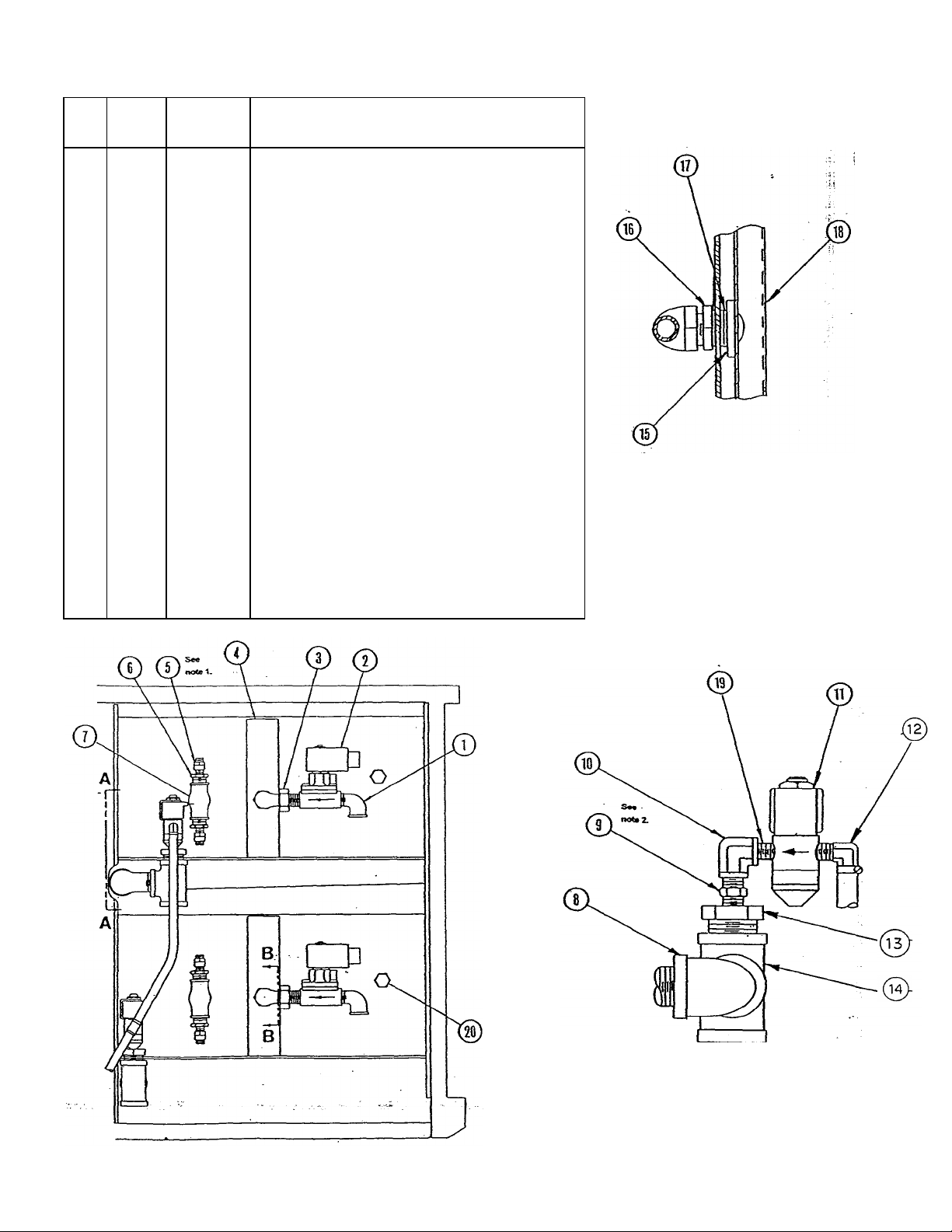
3500 - Control Side Plumbing
SECTION B
-B
NOTES:
SECTION A
-A
ITEM
QTY.
PER
COMP-
1 1 10-2811 STREET ELBOW. 1/2" IPS
2 1 10-5859 VALVE, SOL, 1/2" STM. ( 120 VOLT) 60 Hz
1 10-7340 VALVE, SOL. 1/2" STM. ( 240 VOLT) 60 Hz
3 1 10-4844 EL, UNION, 90 DEGREE, 1/2" IPS. BRASS
4 1 91-3430 CHANNEL
5 2 08-4874 VALVE, PRESSURE RELIEF
6 2 10-3324 BUSHING,REDUCING, 1/2" X 1/4" IPS
7 1 10-3442 TEE, BRASS. 1/2" X 1/2" X 3/4" IPS
8 1 08-4831 ELBOW, 90 DEGREE, B.I., 1" IPS, STREET
9 1 08-4866 NOZZLE, CONDENSER ( NEWER MODELS )
10 1 09-4817 EL, 90 DEGREE, REDUCING, 1/2" X 1/4" IPS.
11 1 08-4821 VALVE, SOL. 1/4" WTR., (120 VOLT) 60 Hz
1 08-4810 VALVE, SOL, 1/4" WTR-, ( 240 VOLT) 50 Hz
12 1 08-4841 STEAM SUPPLY HOSE ( UPPER COMP.)
1 08-4842 STEAM SUPPLY HOSE ( LOWER COMP.)
13 1 08-4867 BUSHING, 1" NPT X 1/4" NPT
14 1 10-8045 TEE, M.I.1" NPT
15 1 08-4407 SPACER, RUBBER
16 1 10-3343 LOCKNUT, 1/2" IPS
17 3 91-6203 GASKET, .859 ID X 1-1/32 OD X 1/8" TK
18 1 91-3240 JET PIPE
19 1 09-4816 NIPPLE, CLOSE, BRASS, 1/8" NPT
20 1 10-8105 COMPARTMENT THERMOSTAT
PART
NUMBER
DESCRIPTION
1. Assemble item 5
2. Assemble item 9
Page 4

PER
NUMBER
1
6429
TRANS., STEP DN.
24
V
ITEM
QTY.
PER
1 1 10-9174
1 08-6343
1 10-9175
1 08-6344
2 1 08-6308
3 1 10-6291
1 10-6293
4 1 10-6682
1 10-6665
5 1 10-5859
1 10-7340
6 1 10-8105
7 1 08-4821
1 08-4810
8 1 10-5016
NUMBER
PART
3500 WIRING SCHEMATIC PARTS LIST
DESCRIPTION
RELAY, 120 VOLT
RELAY, 240 VOLT
SOCKET, RELAY 120 VOLT
SOCKET, RELAY 240 VOLT
REED SWITCH
60 MIN. TIMER 120 V
60 MIN. TIMER 240V
BUZZER, 120 VOLT
BUZZER, 240 VOLT
SOLENOID, STEAM 120 V
SOLENOID, STEAM 240 V
THERMOSTAT, 195 F
COND.. THERM.. 120V
COND., THERM., 240 V
PILOT LT. 120V
ITEM
OPTIONAL -NOT SHOWN
QTY.
1
PART
0808-6450
TIMER, DIGITAL
MODEL: 3500
DESCRIPTION
4
Page 5

ILLUSTRATED PARTS LIST - DOOR ASSEMBLY
QTY.
ITEM
1 1 91 - 6229 OUTER DOOR
2 1 91 - 6241 INNER DOOR
3 1 08-4400 DOOR GASKET
4 1 91 - 6237 GASKET RETAINING PLATE
5 4 10 - 2396 8 - 32 SELF LOCKING SCREW
6 4 08 - 4601 COMPRESSION SPRING
7 1 91 - 6228 DOOR HANDLE
8 4 09 - 3429 1/4-20 X 3/8 HX. HD. BOLT
9 4 10-2513 1/4" INTERNAL TOOTH WASHER
10 2 08-4600 COMPRESSION SPRING
11 2 10-2365 10 - 32 SELF LOCKING NUT
12 2 10-0369 HANDLE CAP
13 4 10 - 0100 1/2 O.D. NYLON WASHER
14 1 09 -1608 LATCH STRIKER CASTING
15 2 10 -1728 8 - 32 X 3/8" LG. FLATHEAD SCREW
16 2 08 - 2702 NYLON FLANGED BEARING
17 1 91-9216 MAGNET, DOOR - NOT SHOWN
PER
COMP.
PART
NUMBER
DESCRIPTION
5
Page 6

3500 - Drain Connection
6
Page 7

3500 CONTROL PANEL ASSEMBLY
QTY.
ITEM
PER
COMP.
1 1 91 - 6350 CONTROL PANEL, 60Hz
2 1 10-5016 PILOT LIGHT
3 1 09 - 5259 KNOB, TIMER
4 1 10-6291 60 MIN. TIMER, 120 V
5 1 10-6682 BUZZER, 120 V
6 1 10-6005 TERMINAL BLOCK
PART
NUMBER
91 - 6351 CONTROL PANEL, 50 Hz
10-6293 60 MIN. TIMER, 240 V
08 - 6429 DIGITAL TIMER
10-6665 BUZZER, 240V
DESCRIPTION
CONTROL PANEL ASSEMBLY VIEW - FRONT & BACK
4
5
7
Page 8

TROUBLE SHOOTING GUIDE
GENERAL
The information In this section Is Intended to assist the operator, maintenance
and the service personnel in locating the source of problems which may occur
with the cooker. Before following any of the procedures given in this section,
the operator/maintenance person should be thoroughly familiar wfth the
operating instructions and the function of all controls as described in the
operating instructions section of this manual. If the problem cannot be readily
corrected without the use of tools the operator/maintenance person should
contact the nearest Market Forge service agency for assistance.
TROUBLES POSSIBLE CAUSE REMEDY
60 minute timer indicator light
fails to light when timer is set
Steam fails to enter cooking
compartment with indicator light
on.
Steam enters compartment
continuously. Timer dial not
turning.
1. Power to cooker is off 1. Locate external breaker and
place it in ON position
Door interlock switch contacts
not closed.
*3. Door interlock switch faulty. 3. Replace switch.
*4. Burned out bulb-faulty light 4. Replace light
*5. Faulty timer contacts. 5. Replace timer.
*6. Faulty selector switch. 6. Replace switch.
*7. Faulty wiring. 7. Inspect condition of wire and
*1. Faulty solenoid valve
*2. Faulty wiring.
*1- Faulty thermostatic switch.
*2. Faulty timer motor.
*3. Faulty steam solenoid valve- 3.Replace valve.
*4. Faulty wiring.
2. Shut cooker door to dose
switch contacts.
tightness of all connections.
Correct as needed.
1. Replace valve
2. Inspect condition of wire and
tightness of all connections.
Correct as needed.
1. Replace switch.
2. Replace timer.
4.Inspect condition of wire and
tightness of all connections.
Correct as needed.
Page 9

direct connect steam control)
TROUBLE SHOOTING GUIDE
TROUBLES POSSIBLE CAUSE REMEDY
Steam continues to flow into
compartment and/or buzzer
fails to sound at end of timer
setting
*1. Timer contacts faulty. 1. Replace timer.
*2. Buzzer faulty. 2. Replace buzzer
Steam flows continuously
from steam generator (or
drain line with cooker in
operation
. *2. Faulty condenser thermostat. 2. Replace thermostat.
*4. Faulty wiring. 3. Inspect condition of wire and
tightness of all connections.
Correct as needed.
1. Cold water not connected. 1. Turn on external shut off valve.
*3. Faulty cold water solenoid. 3. Replace Valve-
*4. Faulty wiring. 4. Inspect condition of wire and
tightness of all connections.
Correct as needed.
Page 10

ITEM PART# QTY REQUIRED DESCRIPTION
*14 10-2513 4 1/4"A" WASHER
*16 10-0369 2 CAP, HANDLE
**17 91-6242 REF. ONLY
ASSY DOOR
*18 08-4601 4 SPRING COMPRESSION BETWEEN
INNER AND OUTER DOOR.
21 10-2403 4 WASHER
1 91-6228 1 HANDLE, DOOR
2 91-6229 1 OUTER DOOR
3 10-0100 8 WASHER,NYLON
4 08-4601 4 SPRING COMPRESSION
5 09-1608 1 STRIKER, DOOR LATCH
6 10-2396 2 NUT, SELF—LOCKING
7 10-1728 2 SCREW, FLATHEAD
8 91-9297 1 LATCH
9 08-2700 2 BEARING
10 10-2396 2 NUT, SELF LOCKING
*11 91-6241 1 RETAINER ASSY, INNER DR
*12 08-4400 1 GASKET, DOOR
*13 08-3406 4 SCREW, BUTTON HEAD
*15 08-4600 2 SPRING, COMPRESSION
19 10-0369 2 END CAPS
20 08-3406 4 SCREW (ADJ)
22 10-2513 4 STARWASHER
*NOT SHOWN IN EXPLO DED VIEW
** To receive a complete door, please list above items with accompanying quantities. The exceptions to this are items
#1,8,9,&10
Door Assembly
10
 Loading...