

Page 1
SERVICE & PARTS MANUAL
Models:
Pressureless Steam Cooker
3500
3550
MARKET FORGE CANADA LTD.
Mississauga, Ontario, Canada
Form No. S-2196 4/79 Printed in U.S.A.
Page 2

TABLE OF CONTENTS
1.2 Basic Fu
nctioning
1-1 5.2 Trouble
-
Shooting Guide
5-1
5.4 Electrical Trouble
-
Shooting
2.1 Assembly
2-1 5.4.1 Incoming Power
5-3 2.2 Setting In Place
2-1 5.4.2 Electrical Inspection
5-3
2.4 Installation Check
-
Out 2-1 5.4.4 15-MINUTE Timer
5-5
2.4.1 Initial Control Settings
2-1 5.4.5 60-MINUTE Timer
5-5
2.4.2 Cooker
Check
-
Out 2-1 5.4.6 Door I
nterlock Switch
5-5 2.4.3 Shut-Down Procedure
2-2 5.4.7 Steam Solenoid Valves
5-5
5.4.8 Indicator Lights
5-5
SECTION
3
OPERATION
5.4.9 Cooking Compartment Thermostat
3.2 Operating
Procedures
3-1 5.4.1.0
Buzzer
5-6
3.2.1 Steam Source Operation
3-1 5.4.1.1
Cold Water Condenser Circuit
5-6
3.2.2 Preheating
3-1 5.4.1.2
Wiring
5-6
3.2.3 Cooking
3-1
3.2.4 Shut-Down Procedure
3-1 SECTION
6
MAINTENANCE
3.3 Cleani
ng
3-2 6.1 General
6-1
SECTION
4
PRINCIPLES OF OPERATION
6.2.1 Door Disassembly and Cleaning
6-1
4.2 Plumbing Circuits
4-1 6.2.3 Cooking Compartment Cleaning
6-1
4.2.1 Steam Inlet Line
4-1 6.3 Repair and Replacement
6-2 4.2.2 Steam Exhaust and Drain Lines
4-1 6.3.1 Door Assembly
6-2
4.2.3 Steam Exhaust Condensing System
4-1 6.3.2 Exterior Panel Removal
6-2
4.2.4 Pressure Safety Valve
4-2 6.3.3 Steam and W
ater Solenoid Valve
4.3 Electrical Circuits
4-2
Replacement
6-2
4.3.1 Control Circuit Components
4-3 6.4 Door Adjustment
6-3
6.4.1 Latch Adjustment
6-3
7.2 Ordering Information
7-1
Paragraph Page Paragraph Page
SECTION 1 INTRODUCTION SECTION 5 TROUBLE-SHOOTING
1.1 Description 1-1 5.1 General 5-1
SECTION 2 INSTALLATION
3.1 Operating Controls and Indicators 3-1
Procedures 5-2
Switch 5-6
4.1 General 4-1 6.2.2 Door Latch Lubrication 6-1
6.4.2 Door Tension Adjustment 6-3
SECTION 7 ILLUSTRATED PARTS LIST
7.1 General 7-1
Page 3

LIST OF ILLUSTRATIONS
Figure
3-2 Pan Support Removal
3-3 6-2 Control Panel Removal
6-2 6-3 Plumbing and Interior View
6-3
SECT ION
4
PRINCIPLES OF OPERATION
6-4 Latch Adjustment
6-3
4-1 Pictorial Diagram
— Steam
&
Water
Circuits
4-2 SE
CTION
7
ILLUSTRATED PARTS LIST
4-2 Pictorial Diagram
— Electrical
7-1 Cabinet Assembly
7-2
Circuits
4-3 7-2 Door Assembly
7-4 7-3 Plumbing Assembly
7-6 SECT ION
5
TROUBLE
-
SHOOTING
7-4 Control Panel
7-8
5-1 Wiring Diagram, Model
3500
5-4 5-2 Schematic Diagram, Model
3500
5-7
3-1
Controls and Indicators
3-3 5-1 General Trouble
-
Shooting Guide
5-1
SECT ION 3 OPERATION
3-1 Controls & Indicators 3-2 6-1 Inner Door Removal 6-1
Page Figure Page
SECTION 6 MAINTENANCE
LIST OF TABLES
Table Page Table
SECTION 3 OPERATION SECTION 5 TROUBLE-SHOOTING
5-2 Electrical Fault Isolation Guide 5-3
Page
Page 4

SECTION 1 INTRODUCTION
This service and parts manual contains general information, installation, operation, principles of operation,
trouble-shooting and maintenance information for the Market Forge 3500 and 3550 Pressureless Steam
Cookers. Also included is a parts list in which each replaceable part is identified and shown in an
accompanying exploded view.
1.1 DESCRIPTION
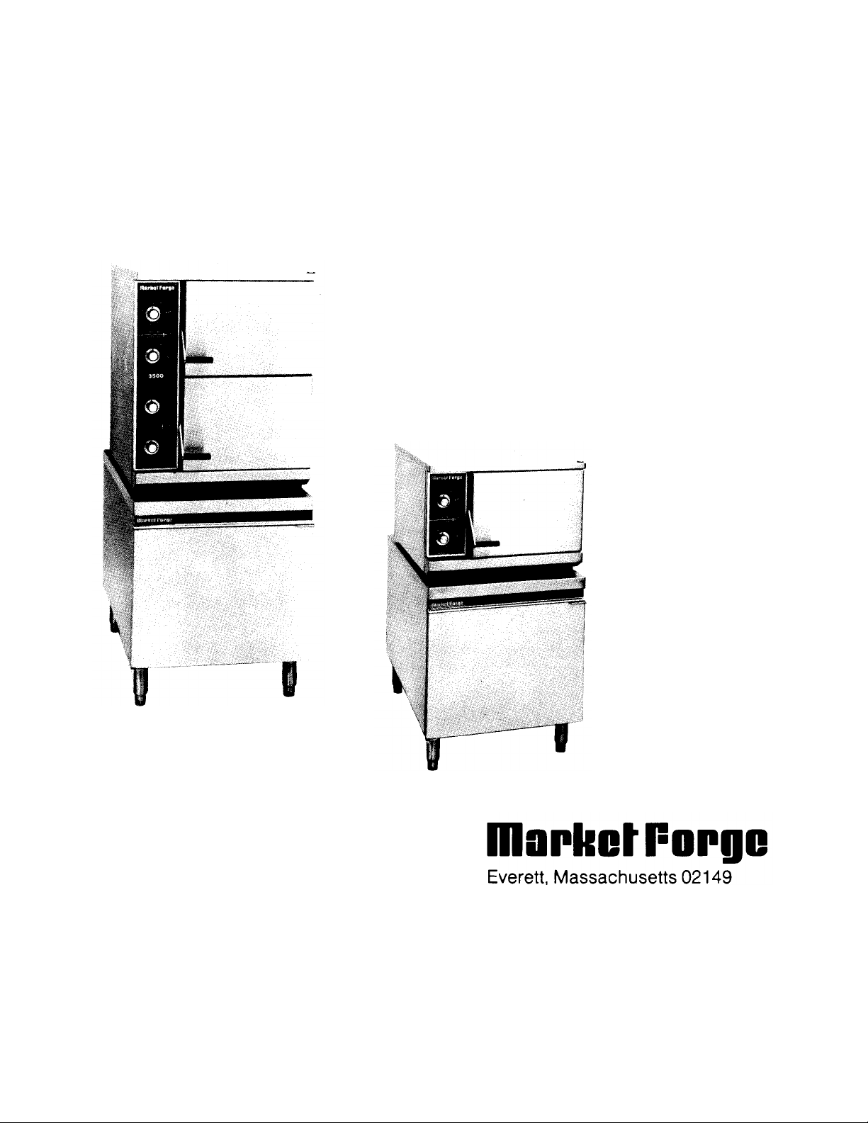
The Model 3500 is a pressureless steam cooker
consisting of two independently controlled
compartments enclosed in a single cabinet. The
model 3550 includes a single compartment. Each
compartment is equipped with a separate two-piece
door with inner gasket plate isolated from the exterior
surface. Door latches operate by cam action for
positive sealing of inner door in one continuous hand
motion. Steam and steam condensing circuits are
electrically controlled. Operating controls are
displayed on a single front -mounted panel, and
include separate timers with indicator lights for
selection of either 15-minute precision timed cooking
or 60-minute long duration cooking.
A separate steam source required for operation of
the Pressureless Cooker is normally purchased with
it, in which case the cooker is factory mounted with
all steam, drain, cold water and electrical interconnections completed. Model 3500/Boiler and 3550/
Boiler configurations with the cookers on 24-inch
wide cabinet bases containing electrically powered
steam boilers (model suffix E)are on the cover. Other
applications include the 3500 or 3550 Cooker on a
gas-fired boiler (model suffix G), a steam coil boiler
(model suffix SC), or a cabinet containing steam and
drain controls for direct connection to a remotely
located boiler (model suffix D). The Model 3500 may
also be mounted on larger boiler cabinets or be combined with other cooking equipment. Model 3550
utilizes the same boiler cabinets, designated by the
same suffixes as for the 3500.
1-1 S-2196
1.2 BASIC FUNCTIONING
The Model 3500 may be operated with only one
compartment in use, or, both may be used
simultaneously (The 3550 has only one
compartment). Each compartment is equipped with
identical controls allowing selection of either 15MINUTE TIMER or 60-MINUTE TIMER operation by
setting a two-position switch. The cooker becomes
operational when the selector switch is set to either
timer position, the timer is set at the desired cooking
time, and the compartment door is closed. The timer
indicator light comes on and the steam solenoid valve
opens allowing steam to flow into the compartment
through a slotted steam standpipe.
When steam flowing inside the compartment has
raised the interior temperature to 212°F, the contacts
of a thermostatic switch automatically close,
completing the circuit to the timer motor and starting
the cooking time period. At the end of the set interval,
timer contacts switch to shut off the cooking operation
and sound a signal buzzer. The buzzer is silenced by
returning the timer dial to the OFF position.
Steam emitted from the compartment along with
liquid cooking drainage is directed through a drain
screen inside the compartment into the cooker drain
line. A cold water solenoid valve connected into the
cooker drain line is automatically actuated by a
thermostatic switch in the boiler drain to condense the
steam to water prior to discharge into the boiler drain.
Page 5

PRESSURELESS STEAM COOKER
1.3 SERVICE
Required service, both preventive and corrective,
is explained in Section 6. Should repairs be
required, a network of authorized agencies is
available to assist with prompt service. A current
Directory of Authorized Service Agencies may be
obtained by contacting:
Product Service Department
Market Forge
35 Garvey Street
Everett, Massachusetts 02149
Product Service Department
Market Forge Canada, Ltd.
1375 Aimco Blvd., Unit 5
Mississauga, Ontario,Canada L4W 1B5
Telephone: (416) 621-9252
The model and serial numbers must be
referenced when corresponding with Market Forge.
The data plate containing the serial number
pertaining to the equipment is located on the lower
front trim of the cabinet.
Telephone: (617) 387-4100
S-2196
Page 6

SECTION 2 INSTALLATION
2-1
S-2196
2.1 ASSEMBLY
The Pressureless Cooker is factory mounted on a
cabinet base containing either a steam boiler or direct
steam connection controls for the cooker. The assembled
unit is shipped bolted to a skid with cabinet feet in a
separate container. Steps required for assembly are as
follows:
1. Remove the four bolts which fasten the equipment
frame to the skid.
2. Install feet in threaded mounting locations of the
cabinet frame.
3. Mount the two pan support racks on studs located
inside the cooking compartment.
4. Attach panels to lower cabinet. Detailed
instructions are enclosed with the panels.
2.2 SETTING IN PLACE
If possible a location should be selected under an
exhaust hood which will remove small amounts of water
vapor emitted when the cooker doors are opened. Level
the unit in final location by turning the adjustable feet.
Using the cabinet top as a reference, obtain level
adjustment left-to-right and front -to-back.
2.3 MECHANICAL CONNECTIONS
Since the Pressureless Cooker is interconnected at the
factory to the steam boiler or direct steam plumbing, no
field connections are required to the cooker. All electrical
and plumbing connections are routed to the steam boiler
cabinet through the 6-inch high space between the floor
and the bottom edge of the cabinet frame. Connection
locations for the cooker mounted on steam boilers of
electric, gas and steam coil utility and direct connected
steam are shown in separate Installation Instructions for
each.
2.4 INSTALLATION CHECK-OUT
After the Cooker is completely assembled and all
mechanical connections made to its steam source (steam
boiler or direct steam connection plumbing), both steam
source and cooker must be given a thorough check-out
before being put into operation. Checkout procedures for
the cooker mounted on steam boilers of electric, gas and
steam coil utility or direct connected steam are given in
separate
Installation Instructions for each. Procedures for the
cooker only are included in subsection 2.4.2. If the cooker
fails to perform as described, consult Table 5-1 of the
Trouble-Shooting Guide for corrective action. If difficulty
arises with the boiler, reference the separate service and
parts manual for that equipment.
Before making this check-out the operator must be
thoroughly familiar with the operating procedures in
Section 3, and with the function of each control described
in Table 3-1. Reference Figure 3-1 for identification of
controls required in the following procedures.
2.4.1 Initial Control Settings
Before beginning the start-up procedures for the
cooker, the instruction plate and service manual for the
steam boiler must be consulted and all start-up
procedures completed to supply 15 PSI steam to the
steam inlet line for the cooker.
1. All steam boiler controls are in the operating mode
and 15 PSI steam is applied to the cooker inlet
plumbing.
2. Cooker timers for both compartments (Figure 3-1;
3, 4) are in the OFF position.
3. Cooker compartments are empty of all information
materials, pan supports are mounted in place and
doors are open.
2.4.2 Cooker Check-Out
The cooker check-out procedures are as follows:
1. Place selector switches (Figure 3-1, 2) in 15 MINUTE
TIMER (up) position.
2. Set 15-Minute Timers (3) to about the "4-minute"
position. Observe that indicator lights are off and
steam does not enter compartments.
3. Close cooker compartment doors being certain latch
handles (1) are in the down position and latches are
securely engaged. Observe that indicator lights turn
on and steam can be heard rushing int o the
compartment simultaneously with the door closing.
4. Observe the boiler drain line for passage of steam
into the open floor drain. Correct steam condenser
operation is evidenced by presence of water flowing
from the drain line.
Page 7

2-2 PRESSURELESS STEAM
COOKER
5. Observe cooker operation for several minutes.
Operation is correct if timer dials begin to rotate
after a short delay period required for preheating.
After the delay period plus the "4-minute" initial
setting, the timer dials will return to the "0-
Pressureless Cooker except to check that all timer
dials (3, 4) are in the OFF position and the
compartment doors are open. Consult the steam
boiler instruction plate and complete the shut-down
procedures for the boiler.
minute" position at which a buzzer sounds. The
buzzer is silenced by turning the dial to the OFF
position.
6. Open cooking compartment doors and repeat
Steps 1 through 5 for the 60 MINUTE TIMER
(down) position of selector switch (1).
Before final check-off of the Cooker/Boiler
system for use in cooking, boiler start-up and
shut-down must be completed two more times
NOTE
to insure cleanliness and proper operation.
2.4.3 Shut-Down Procedure
No shut -down procedure is required for the
S-2196
Page 8

SECTION 3 OPERATION
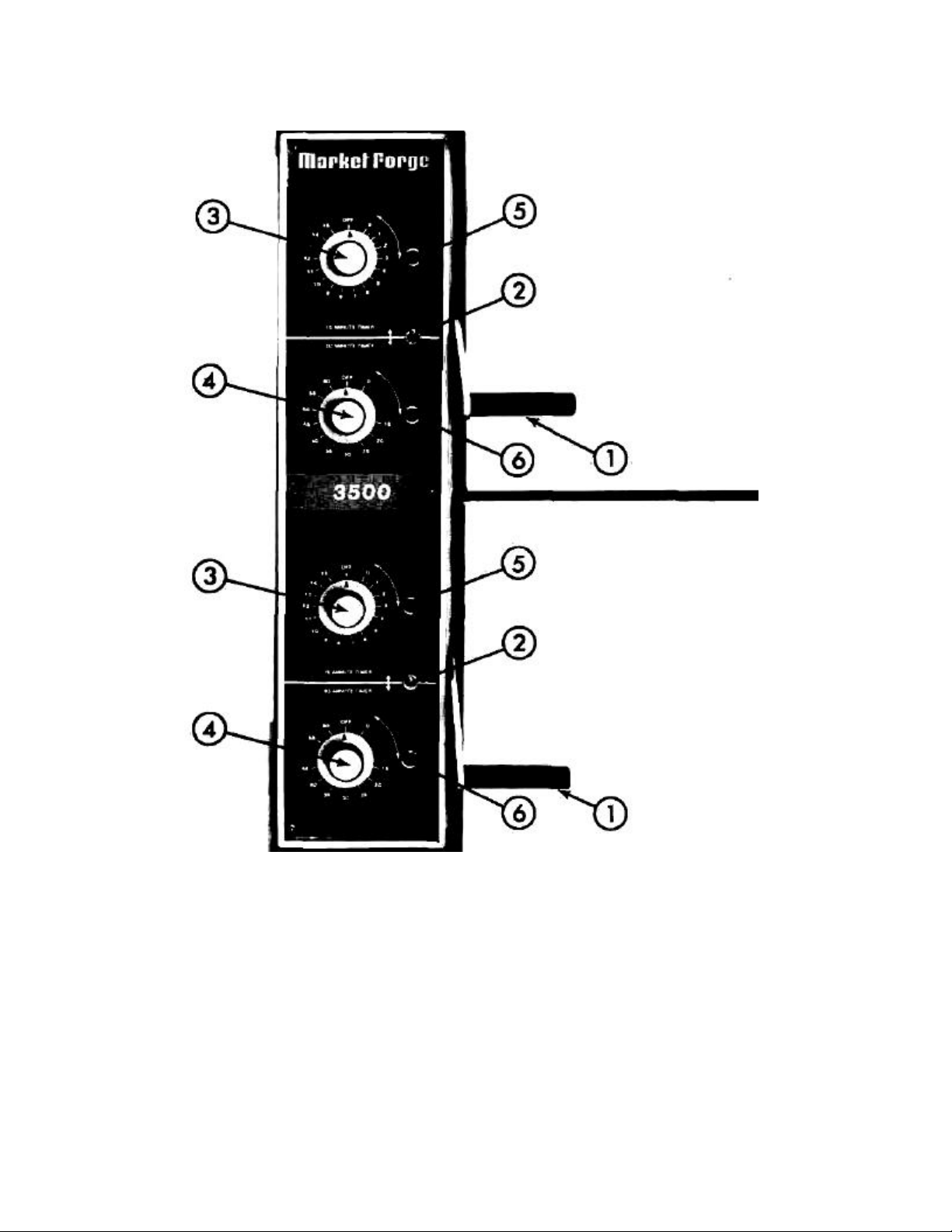
3.1 OPERATING CONTROLS AND INDICATORS
The controls and indicators required to operate the
Pressureless Steam Cooker are listed in Table 3-1,
together with a short functional description of each.
Figure 3-1 shows the physical location of each
control and indicator.
3.2 OPERATING PROCEDURES
The 3500 and 3550 are pressureless steam
cookers which defrost frozen foods and cook fresh
and defrosted foods. Each cooking compartment
permits selection of either short duration (0-15
minutes) timing or long duration (0-60 minutes)
cooking periods. Instructions for operation are
included in this section. Consult Test Kitchen
Bulletin #59 for detailed cooking information.
3.2.1. Steam Source Operation
The Pressureless Cooker is supplied mounted
on a cabinet containing either a steam boiler or
controls for direct connected steam. Manual
controls are accessed by opening the cabinet door.
The start -up procedure for the steam source is
completed once before each daily operating period
of the cooker. (For steam boilers see instruction
plate.)
3.2.2 Preheating
Before each initial operation of the cooker, and
at any other time when the cooking compartment is
cold, a 1-minute preheating period is required. To
preheat the cooker put steam source into operation
and proceed as follows:
1. Close cooking compartment door and latch
securely by pushing down on latch handle (1).
2. Place selector switch (2) for compartment(s) to
be used in 15-MINUTE TIMER (up) position.
3. Set 15-Minute Timer Dial (3) to "1-minute"
setting.
NOTE
Total elapsed preheating time equals the timer
setting plus a short delay period needed to
activate a thermostatic switch included in the
controls.
4. Turn off buzzer which sounds to indicate
cooking is complete by setting the 15-Minute
Timer Dial (3) to OFF position.
3.2.3 Cooking
Before loading the cooker, be sure compartment
is hot. See 3.2.2 for preheating instructions.
1. Slide pans of food into cooking compartment
pan supports.
2. Close cooking compartment door and push
down on latch handle (1) to engage.
3. Place Selector Switch (2) in required position:
a. 15-MINUTE TIMER—For short duration
timing.
b. 60-MINUTE TIMER— For long cooking
periods.
4. Set appropriate timer to the required cooking
time (see Test Kitchen Bulletin #59).
5. Turn off buzzer which sounds to indicate
cooking is complete by setting timer dial (3 or
4) to the OFF position.
6. Open door by lifting up on latch handle (1).
7. Unload by sliding pans of food from pan
supports, taking care to avoid hitting
compartment opening.
3.2.4 Shut-Down Procedure
No shut -down procedure is required for the
cooker except to check that both timer dials (3, 4)
are in the OFF position, and that both compartment
doors are open. When all cooking has been
completed for the day the steam source must be
shut off. (For steam boilers see instruction plate.)
3-1 S-2196
Page 9
3-2 PRESSURELESS STEAM COOKER
3.3 CLEANING
After each period of daily operation (more
frequently as required to maintain cleanliness) the
cooker should be thoroughly cleaned by completing
the following steps:
1. Remove left and right side pan supports (Figure
3-2) by lifting up and off mounting studs. Wash
with detergent using a brush to clean drain
screen.
i-2196
Figure 3-1. Controls & Indicators
Rinse and set aside for reassembly.
2. Wash cooking compartment interior using
detergent and water. Rinse and dry thoroughly.
3. Replace pan supports in compartment and Leave
door open.
NOTE
Supports with drain screens must be installed on
left side of each compartment.
Page 10
OPERATION
The cooking interval selector switch. Placed in up
Fig. 3-1 Ref. Description Function
TABLE 3-1
CONTROLS AND INDICATORS
(See Figure 3-1)
1 Latch Handle
Selector Switch
2
15-MINUTE TIMER/60-
MINUTE TIMER
3 15-Minute Timer
4 60-Minute Timer
5
6
Indicator Light (red)
15-Minute Timer
Indicator Light (red)
60-Minute Timer
Secures cooker door in closed position. Lift to
open.
position for 15-minute maximum timed interval;
down position for 60-minute maximum timed
period.
Controls short interval precision timed cooking
from 0 to 15 minutes.
Controls longer duration cooking times from 0 to
60 minutes.
Indicates when lit that cooker is in operation
controlled by 15-minute timer.
Indicates when lit that cooker is in operation
controlled by 60-minute timer.
7 Buzzer Signals end of cooking Period (not shown).
Figure 3-2. Pan Support Removal
Page 11

SECTION 4 PRINCIPLES OF OPERATION
4.1 GENERAL
The 3500 Pressureless Steam Cooker consists of
two identical cooking compartments, one above the
other, in a single cabinet assembly. (Model 3550 has
only one compartment.) Each compartment is fitted
with independent electrically controlled steam circuits
and spring loaded, self-sealing doors with cam-action
latches. Compartments can be used separately (or
simultaneously for model 3500) for either of two timed
intervals— 15-minute maximum timing' or long
duration 60-minute maximum timing. The principles of
operation in this section include an explanation of
steam, steam condensing and electrical circuits and
their functioning for the Model 3500. Operation is
identical for the single compartment 3550.
4.2 PLUMBING CIRCUITS
The plumbing circuits consist of the piping, steam
solenoid valves, steam jet pipe, drain, cold water
condenser, and pressure safety relief valve required
to provide controlled steam application to the cooking
compartments. A simplified diagram of these circuits
for model 3500 is shown in Figure 4-1.
NOTE
Figure 4-1 is strictly a pictorial schematic
diagram and is not intended to show the actual
configuration of the plumbing. All components
are shown in correct relationship with each
other. However, the diagram does not show their
actual locations or position within the cooker.
As shown in the diagram, steam inlet and exhaust
connections are connected at the factory directly into
a steam boiler or direct connected steam plumbing
enclosed within a base cabinet on which the cooker is
mounted. The boiler (or direct connected steam
control system) is equipped to supply constant,
regulated steam at 14-15 PSI. Steam exhaust, having
been reduced to water by the cold water condenser, is
directed into the boiler (or direct connected steam
control) drain system.
Steam inlet lines for compartments are equipped
with normally closed solenoid valves operated by the
electrical control circuits. The inlet valves are opened
whenever the compartment control circuit is activated
by use of either the 15-minute or 60-minute timers.
4-1 S-2196
4.2.1 Ste am Inlet Line
A steam supply line is plumbed from the boiler
output (or direct connected steam control), to a 1/2
inch "T" fitting connected to the input sides of both
steam inlet solenoid valves. At all times when a
cooking compartment is not in use the valve for the
compartment remains closed to prevent steam from
entering. During operation the appropriate inlet
solenoid valve is opened by activation of the control
circuit. Steam is projected onto the surface of pans of
food loaded into the compartment by a jet pipe
located inside the compartment. Steam continues to
flow through the compartment in this manner until the
control circuit closes the solenoid valve.
4.2.2 Steam Exhaust and Drain Lines
Steam exhaust and compartment drainage are
removed from the cooking compartments by a
separate line from each, connecting with the boiler (or
direct connected steam plumbing) drain system.
Perforated strainers at the drain line openings inside
each compartment allow only steam, condensation
and liquid cooking drainage to enter. Prior to
discharge into the boiler drain system, steam is
converted to water by the cold water condensing
systems for each compartment.
4.2.3 Steam Exhaust Condensing System
The steam condensing system consists of the
identical, two-position, normally closed cold water
solenoid valves (one only in the model 3550) with
outlet sides connected into the exhaust plumbing for
each cooking compartment. A spray nozzle directs
cold water about the inside of the drain lines to
increase cold water contact with exhausted steam.
Valve inlet sides are connected to the cold water
supply line of the steam boiler (or direct connected
steam plumbing). The valves function simultaneously
(even though only one compartment may be in use)
and independently of other cooker controls, in
response to a thermostatic switch located at the
discharge opening of the boiler drain line. The switch
allows the valves to open at all times when the drain
temperature exceeds 193°F.
Page 12

4-2
P
SSURELESS STEAM COOKER
Figure 4-1. Pictorial Diagram. Steam & Water Circuits — Model 3500
4.2.4 Pressure Safety Valve 4.3 ELECTRICAL CIRCUITS
A coupling mounted on the side of each The electrical circuits of the cooker control the
compartment is fitted with a pressure relief valve. The power to activate timer motors and energize solenoid
valves provide pressure overload protection for each operated valves and circuits which in turn control cooking
compartment in the unlikely event of a drain application of steam to the cooking compartment and
blockage. Relief valves are of the spring loaded, condensation of steam from the exhaust line. The
poppet type, pre-set to open automatically at cooker operates on 120V, 2 amp, 60Hz (50 Hz on
pressures in excess of 0.5 PSI. special order) electrical service connected to all
S-2196
RE
Page 13

PRINCIPLES OF OPERATION
circuits from the circuits of the steam boiler (or direct
connected steam controls) contained within the
cabinet on which the cooker is mounted. Power is
supplied to the control circuit at all times when the
shut-off device for the unit (supplied by the user) is
in the ON position.
4.3.1 Control Circuit Components
The control circuit is shown in pictorial diagram
Figure 4-2. The diagram shows only one
compartment as in the model 3550, or one of the
two identical compartments of the 3500. A brief
description of the electrical circuit elements follows.
4.3.1.1 Selector Switch
The selector switch is a triple-pole, double throw
switch. One set of contacts applies 120 volt input to
the common element (1) of either the 15-minute or
60-minute timers. The second set of contacts closes
the circuit from the door interlock switch to the
indicator light for either the 15-minute of 60-minute
timer. The third set of contacts closes the circuit
between circuit interrupters (door interlock switch
and thermostatic time delay switch) and the timer
motor for either the 15-minute or 60-minute timers.
Figure 4-2. Pictorial Diagram. Electrical Circuits, One
Compartment & Condenser
4.3.1.2 15-Minute Timer
The timer contains a 120 volt ac synchronous
motor which drives a timing dial through a gear
reduction and clutch mechanism. The timer dial is
manually set for any interval of operation from 0-to
15-minutes as read on the calibrated dial face. The
manual rotation of the dial moves the common
element (1) of the timer switch from the neutral
(OFF) position to contact (3) which connects with the
steam inlet solenoid valve operating circuit.
The cooker is placed into automatic operation with
the setting of the timer dial. Its timing cycle,
however, is automatically delayed by a thermostatic
switch which assures operating temperature is
achieved before the timer motor begins to "time out".
When the timer motor has operated for the preset
duration, the common element is transferred to
contact (4), returning the inlet solenoid valve to the
closed position and energizing the buzzer. Contact
to the buzzer circuit remains closed until the dial is
manually turned to the OFF position, returning the
common element (1) of the timer switch to the
neutral position.
4.3.1.3 60-Minute Timer
The timer operates in the same manner as the 15-
Minute Timer but with a maximum time setting of up to
60 minutes.
4.3.1.4 Indicator Lights
A separate indicator light is included for the 15-
Minute Timer and the 60-Minute Timer. The light
remains on (red) at all times when the coinciding timer
dial is set and the door interlock switch is closed. It
turns off at the end of the timed cooking duration.
4.3.1.5 Buzzer
The buzzer is an alarm device which operates by
oscillation of a striker against the core of an
electromagnet. When either the 15-Minute or 60Minute Timer dials reach "0-Minutes"the buzzer coil is
energized to sound the buzzer. Movement of the timer
dial to the OFF position opens the contact to the
buzzer coil to shut it off.
S-2196
Page 14

4-4 PRESSURELESS STEAM COOKER
4.3.1.6 Door Interlock Switch
The interlock switch is a single pole, two-position,
microswitch with normally open contacts. The
switch lever is operated by contact with the door.
When the door is open the switch contacts remain
cooking compartment. The switch functions to delay
timer motor operation until the compartment
temperature reaches 193°F., thus assuring that
cooking temperature exists throughout the timed
duration.
in the open position. When the door is closed and
securely latched in place, the switch lever is
depressed to close the contacts. Connected
between the operating contact (3) of the timers and
the steam inlet solenoid valve, the door switch acts
as a protective device to interrupt valve operation
unless the door is closed.
4.3.1.8 Thermostatic Steam Condenser Switch
The switch is included in the boiler drain line
system (or direct connected steam controls) where it
monitors the temperature of discharge from the drain
line. The switch is normally open, closing whenever
4.3.1.7 Thermostatic Time Delay Switch
The thermostatically operated time delay is a two-
position, normally open switch mounted on the
the temperature reaches 193°F. Operating
independently of other control components it is the
sole control device for the cold water solenoid valves
of the steam condensing system.
S-2196
Page 15

SECTION 5 TROUBLE-SHOOTING
1. 15
MINUTE INDICATOR LIGHT FAILS TO LIGHT WITH SELE
CTOR SWITCH IN
15
MINUTE TIMER
5.1 GENERAL
The information in this section is intended to
assist both the operator and service personnel in
locating the general source of problems which may
occur with the cooker. Before following any of the
procedures given in this section, the operator
should be thoroughly familiar with the operating
instructions and the function of all controls which
are described in Section 3. If the problem cannot
be readily corrected, the operator should contact
the nearest Market Forge service agency for
assistance.
GENERAL TROUBLE -SHOOTING GUIDE
PROBLEM
Probable Cause Remedy
5.2 TROUBLE-SHOOTING GUIDES
A trouble-shooting guide for use by service
personnel is given in Table 5-1.
5.3 ELECTRICAL FAULT ISOLATION
Correction of an electrical failure first requires
isolation of the fault to a single circuit or component.
In most cases the nature of the failure and its effect
upon the operation of the cooker will be sufficient to
isolate it to one or more circuit elements. Table 5-2 is
provided as a guide for isolating electrical faults.
TABLE 5-1
POSITION AND 15 MINUTE TIMER SET.
a. Power to Cooker off. Locate external circuit breaker for incoming power and
place in ON position.
b. Door interlock switch contacts not closed. Shut cooker door to close switch cont acts. Check
alignment of door with switch button.
c. Door interlock switch faulty. Replace switch. See subsection 5.4.6
d. Indicator light burned out. Replace light.
e. Faulty timer contacts. Replace timer. See subsection 5.4.4 and 5.4.5.
f. Faulty selector switch. Replace switch. See subsection 5.4.3
g. Faulty wiring. Inspect condition of wire and tightness of all connections.
Correct as needed.
2. 60 MINUTE INDICATOR LIGHT FAILS TO LIGHT WITH SELECTOR SWITCH IN 60 MINUTE TIMER POSITION AND 60
MINUTE TIMER SET. See item 1a. through g.
5-1 S-2196
Page 16

5-2 PRESSURELESS STEAM COOKER
c. Faulty steam solenoid valve.
Replace valve.
See subsection 5.4.7
c. Faulty cold water solenoid
Replace valve.
TABLE 5-1 (cont.)
PROBLEM
Probable Cause
3. STEAM FAILS TO ENTER COOKING COMPAFTMENT WITH INDICATOR LIGHT ON.
a. Faulty steam solenoid valv e.
b. Faulty wiring. Inspect condition of wire and tightness of all connections.
4. STEAM ENTERS COMPARTMENT CONTINUOUSLY. TIMER DIAL NOT TURNING.
Remedy
Replace valve. See subsection 5.4.7.
Correct as needed.
a. Faulty thermostatic switch.
b. Faulty timer motor.
d. Faulty selector switch.
e. Faulty wiring. Inspect condit ion of wire and tightness of all connections.
5. STEAM CONTINUES TO FLOW INTO COMPARTMENT AND/OR BUZZER FAILS TO SOUND AT END OF TIMER
SETTING.
a. Timer contacts faulty.
b. Buzzer faulty.
c. Faulty wiring.
Replace buzzer. See subsection 5.4.1
6. STEAM FLOWS CONTINUOUSLY FROM BOILER (OR DIRECT CONNECTED STEAM CONTROL)
DRAIN LINE WITH COOKER IN OPERATION.
a. Cold water not connected. Turn on external shut off valve.
b. Faulty condenser thermostat.
Replace switch. See subsection 5.4.9
Replace timer. See subsection 5.4.4 and 5.4.5.
Replace switch. See subsection 5.4.3
Correct as needed.
Replace timer. See subsection 5.4.4 and 5.4.5.
Inspect condition of wire and tightness of all connections.
Correct as needed.
Replace thermostat. See subsection 5.4.11.
d. Faulty wiring. Inspect condition of wire and tightness of all connections.
5.4 ELECTRICAL TROUBLE -SHOOTING PROCEDURES
Before performing the trouble-shooting procedures in this
section the serviceman must be familiar with the function of
all controls as described in Section 3 and with the
Principles of Operation described in Section 4.
Electrical trouble-shooting procedures which follow
require access to components and terminals of
S-2196
Correct as needed.
the electrical control panel shown in Figure 7-4.
Electrical controls are reached by removing screws
(Figure 7-4, 1) which fasten the control panel (Figure
7-4,2,3) to the frame. The panel may be pulled
forward for testing while interconnected to the cooker
circuits or disconnected at the 12 pin connection (17)
for complete removal and repair. Wiring and terminal
locations are shown in Figure 5-1.
Page 17

TROUBLE SHOOTING , 5-3
b. Selector switch
TABLE 5-2
ELECTRICAL FAULT ISOLATION GUIDE
FAILURE FAULT LOCATION
1.
Will not operate in either 15-
MINUTE or 60-MINUTE TIMER
positions.
2.
Operating in 15-MINUTE TIMER position
but not in 60-MINUTE TIMER position.
3.
Operates in 60-MINUTE TIMER position
but not in 15-MINUTE TIMER position.
Steam solenoid valve fails to open
with indicator light on.
5.
Indicator light off with steam
solenoid valve open.
6.
With indicator light on and steam
solenoid valve open, timer dial fails
to turn.
7.
Buzzer fails to sound at end of
either 15-Minute or 60-Minute Timer
modes
a. Incoming power
c. Door Interlock switch
d. Wiring
a. Selector switch
b. 60-Minute Timer
d. Wiring
a. Selector switch
b. 15-Minute Timer
c. Wiring
a. Solenoid valve coil 4.
b. Wiring
a. Indicator light
b. Selector switch
c. Wiring
a. Compartment thermostatic switch
b. Selector switch
c.
Timer motor
d. Wiring
a. 15-or 60- minute timer contacts
b. Buzzer
c. Wiring
8.
Steam flows continuously from boiler
drain line.
5.4.1 Incoming Power
Before trouble-shooting any of the electrical parts
or assemblies, verify that power is being supplied to
the cooker. Incoming power is connected at the
boiler (or direct connected steam) control box
located in the base cabinet. With power connected
to the cooker an a-c volt-meter is used to measure
120 volts across L1 and L2. If 120 volts is present,
and the cooker will not operate, the fault lies within
the electrical circuits of the cooker.
5.4.2 Electrical Inspection
The first step in any electrical trouble-shooting
procedure is a thorough physical inspection of all
wiring connections. To access electrical
components
a. Condenser thermostatic switch
b. Cold water solenoid valve
c. Wiring
remove the control panel as explained in subsection
6.3.2.
WARNING
Before removing control panel or checking
connections and wiring be sure that the circuit
breaker for incoming power is OFF. When power
is supplied all exposed terminals of the control
panel carry 120 volts.
Check all wiring connections by hand to assure that
both ends of all connection points are tightly secured.
Use a screwdriver to tighten connection points. If
necessary visually inspect all quick-disconnect
terminals for evidence of corrosion. Terminals in this
condition should be separated, cleaned with emery
cloth until shiny and tightly reconnected.
S-2196
Page 18

5-4 PRESSURELESS STEAM COOKER
Figure 5-1. Wiring Diagram, Model 3500
5.4.3 Selector Switch
A defective Selector Switch may be the cause of
failure of either cooker compartment to operate in
both 15 MINUTE TIMER and 60 MINUTE TIMER
positions, or failure to operate in one position only. To
check the Selector Switch, proceed as follows:
1. Turn off power to the cooker at external circuit
breaker.
2. Disconnect all wires from Selector Switch
terminals (Figure 5-1).
3. Connect an ohmmeter between one of the
common terminals (2, 5, 8) and either of the
S-2196
outside terminals for that pole of the switch (e.g.
common terminal 2 and terminal 1).
4. Operate switch to close contacts to terminals
being tested. If a zero ohm reading cannot be
obtained, switch is defective and must be
replaced.
5. Move ohmmeter lead from outside terminal to
opposite outside terminal for that pole, (e.g.
common terminal 2 and terminal 3), and repeat
step 4.
6. Remove ohmmeter and replace all leads on
Selector Switch as shown in Figure 5-1.
Page 19

TROUBLE SHOOTING
5-5
5.4.4 15-MINUTE Timer
5.4.4.1 Timer Contacts
Defective timer contacts will result in failure of
either cooker compartment to operate for the 15
MINUTE TIMER duration. If either compartment fails
to operate in the 15 MINUTE TIMER mode, but
functions correctly in the 60 MINUTE TIMER mode,
the fault is with the 15 Minute Timer contacts or its
wiring. When this occurs, remove the control panel
(subsection 6.3.2), and proceed as follows:
1. Turn off power to the cooker at external circuit
breaker.
2. Disconnect all five wires from timer terminals (see
Figure 5-1).
3. Connect an ohmmeter between terminal 1 and 3.
4. Rotate timer dial beyond the "0-minute" point (any
setting) to obtain a reading of zero ohms on the
ohmmeter. If zero ohm reading cannot be
obtained, timer contacts are defective and the
timer must be replaced.
5. Move ohmmeter leads to terminals 1 and 4.
6. Rotate timer dial to 0-MINUTE position. (An
audible click indicates correct position). If zero
ohm reading cannot be obtained, the timer is
defective and must be replaced.
7. Remove ohmmeter and replace all five leads on
timer terminals as shown in Figure 5-1.
the motor fails to operate, it is defective and the
entire timer must be replaced. 4. Shut off power to
the cooker.
5.4.5 60-MINUTE Timer
Test the 60-Minute Timer contacts and motor in the
same manner as for the 15-Minute Timer. See 5.4.4.
5.4.6 Door Interlock Switch
Malfunction of the cooker door interlock switch
prevents timer indicator lights from turning on and
steam solenoid from opening when the timer dial is
set. If steam does not enter the compartment and the
indicator light fails to turn on with the door latch
securely engaged, the fault may be in the door
interlock switch. Proceed as follows:
1. Turn off power to the cooker.
2. Disconnect wires to the door switch terminals (see
Figure 5-1).
3. Connect an ohmmeter between the terminals of
the switch.
4. Actuate the switch by closing the cooking compartment door. If a zero reading cannot be obtained, the switch is defective and must be replaced.
5. Remove the ohmmeter and replace the leads on
switch terminals. (See Figure 5-1).
5.4.4.2 Timer Motor
A defective timer motor will cause continuous
operation in the 15-MINUTE TIMER mode with the
timer dial failing to return to the "0-Minute" position.
Since thermostatic switch failure can cause the same
symptom, fault must first be isolated to the timer by
attempting operation of the compartment in the 60Minute Timer mode. If the cooker operates correc tly
using the 60-Minute timer, then the 15-Minute timer
motor is faulty. If both timer dials fail to turn, then the
cause of malfunction is probably not the 15-Minute
Timer motor. To confirm timer motor condition,
proceed as follows:
1. Carefully check mot or wire leads and tighten loose
connections.
WARNING
Use care while working with control panel.
Terminals carry 120 volts.
2. Turn on power to the cooker.
3. With Selector Switch in the 15 MINUTE TIMER
position, set timer dial (any setting beyond "0Minute"). If operation is correct the motor will turn
the dial toward "0-Minute". If
5.4.7 Steam Solenoid Valves
When either inlet solenoid valve fails to operate, the
fault may be a defective coil. A defective coil is found
using an a-c volt meter to check the voltage at the coil
wire terminals, with the cooker compartment operating
in either 15 MINUTE TIMER or 60 MINUTE TIMER
modes. If voltage of 120 volts is present and the coil
fails to close the valves, the fault is in the valve coil.
Defective valve coils are not separately replaceable,
requiring complete valve replacement.
5.4.8 Indicator Lights
If the cooker compartment functions correctly with
the single exception that the indicator light fails to light
during operation, the fault is a defective indicator light.
A "burned-out" or defective light is verified by using an
a-c volt meter at the leads, with input power on the
selector switch in the correct position for that timer,
the timer set and the door latches closed. If 120 volts
is present the fault is in the indicator light and requires
replacement. If 120 volts is not present, the fault is in
the wiring or control components (selector switch,
timer, door switch).
S-2196
Page 20

5-6 PRESSURELESS STEAM COOKER
5.4.9 Cooking Compartment Thermostatic
Switch
A thermostatic switch included in the circuit for
the timer motor delays timer operation until steam
flowing into the compartment satisfies the
temperature actuated switch device. If a timer
motor fails to operate within about 1 minute after
the indicator light comes on (with cooker
compartment empty)the cause may be a defective
thermostatic switch. To test the switch proceed as
follows:
1. Disconnect the two wires connected to the
thermostatic switch terminals.
2. Connect an ohmmeter between the two
terminals of the switch.
3. Place the cooker into operation and observe
ohmmeter dial. Within 1 minute of operation,
the switch contacts close automatically to
register a zero ohm reading on the dial. If a
zero ohm reading is not obtained the switch is
defective.
2. Remove wires 3 and 52 from the thermostat
switch terminals.
3. Connect an ohmmeter between the two
terminals of the switch.
4. Place the cooker into operation and observe the
ohmmeter dial. Shortly after steam is observed
exiting the drain line, the thermostat contacts
should close as evidenced by a zero ohm
reading on the dial. If a zero ohm reading is not
obtained the switch is defective.
5. Shut off cooker, disconnect ohmmeter leads,
and replace wires 3 and 52.
If the condenser thermostat functions correctly but
either of the cold water solenoid valves fail to
operate, the cause might be a faulty valve coil. A
defective coil is found using an a-c volt meter to
check the voltage at the coil wire terminals with the
cooker compartment in operation. If voltage of 120
volts is present and the valve fails to open, the fault
is in the valve coil. Defective valve coils are
separately replaceable.
4. Shut off cooker, disconnect ohmmeter leads
and replace wires on switch terminals.
5.4.10 Buzzer
If the buzzer does not sound at the termination of
the operator selected timer setting (timer dial
returned to "0-Minute" position), the fault may be a
defective buzzer. Buzzer operation is verified using
an a-c volt meter at buzzer coil connections with
input power on, selector switch and coinciding timer
dial set at the "0-Minute" position. If voltage is 120
volts, the fault is in the buzzer which must be
replaced. If 120 volts is not present, the fault is in the
wiring or control components, (timer, selector
switch).
5.4.11 Cold Water Condenser Circuit
If during cooker operation steam exits from the
drain line opening (located in lower boiler
compartment) and the condensing system fails to
operate, as evidenced by repeated discharge of
water from the drain line, the condensing circuit is
malfunctioning. The failure can be caused by a
defective condenser thermostat, cold water solenoid
coil or wiring failure. To test the condenser
thermostat proceed as follows:
5.4.12 Wiring
All of the electrical components of the Cooker
(selector switch, timers, indicator lights, switches,
etc.) are connected to each other by wiring shown in
Figure 5-1. If all of the electrical components are
operating correctly (and the incoming power has
been checked), but the cooker fails to operate the
fault lies in the wiring.
Figure 5-1 is a diagram which shows all terminals
and interconnections within the electrical circuits. All
numbered terminals are identified and all leads
number coded as shown. Connections can be easily
removed. Figure 5-2 shows the same information
schematically and is an aid in isolating circuits for
testing.
Using an ohmmeter wiring continuity between the
connections shown on the wiring diagram (Figure 5-
1) are readily verified. This is best done in stages,
removing only those wires required for each
continuity check. As each lead is replaced it should
be checked for evidence of corrosion and cleaned if
necessary. All leads must be tightly attached so as
to provide a good electrical connection.
1. Remove the cover from the control box located
inside the boiler compartment.
S-2196
Page 21

TROUBLE SHOOTING . 5-7
Figure 5-2. Schematic Diagram. Model 3500
S-2196
Page 22

SECTION 6 MAINTENANCE
6.1 GENERAL
This section contains both preventive and corrective
maintenance information. Preventive maintenance may be
performed by maintenance personnel at the establishment
in which the cooker is installed. It is recommended that
user personnel never attempt to make repairs or
replacements to the equipment without the assistance of
authorized service. Assistance in service methods or a
current Directory of Authorized Agencies may be obtained
from Market Forge. (See paragraph 1.3 in Section 1).
6.2 PREVENTIVE MAINTENANCE
A good preventive maintenance program begins with
the daily cleaning procedure described in paragraph 3.3 in
Section 3. Additional preventive maintenance operations
are presented in this section. In establishments which
employ full-time maintenance personnel, the tasks
described can be assigned to them. For other installations,
tasks requiring mechanical or electrical experience should
be performed by an authorized service agency.
The following paragraphs set forth minimum preventive
maintenance procedures which must be completed
periodically to assure continued trouble-free operation of
the cooker.
CAUTION
Under no circumstances should hardware (or parts)
be replaced with a different length, size or type other
than as specified in the parts list. The hardware
used in the Cooker has been selected or designed
specifically for its application and the use of other
hardware may damage the equipment and will void
any warranty.
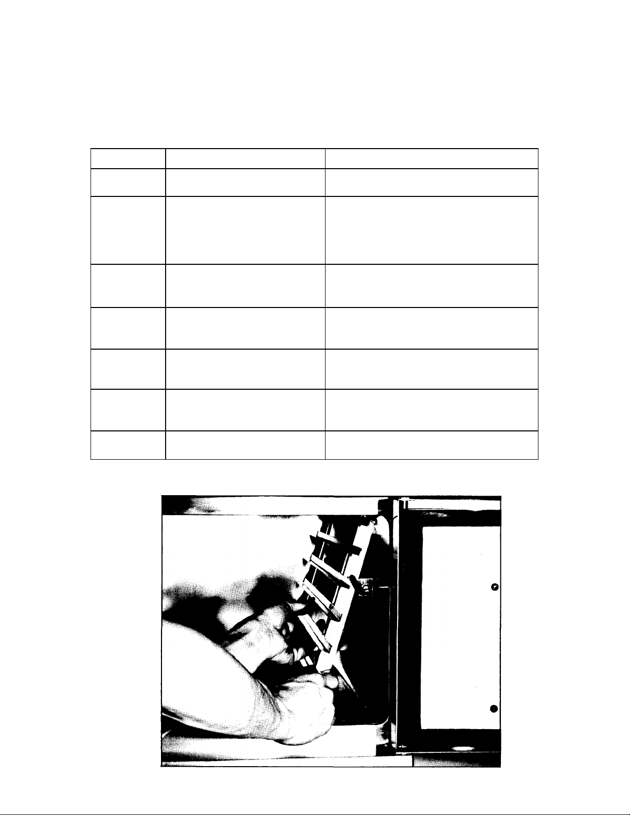
6.2 1 Door Disassembly and Cleaning
The inner doors must be removed from the outer doors
of each cooking compartment for weekly cleaning. With
the door open, the inner door is grasped firmly on the right
side and pushed upward until it is disengaged from the
outer door pins. (See Figure 6-1). Both inner door and
inside surface of the outer door should be thoroughly
cleaned with mild detergent -water solution, rinsed and
dried. The doors
6-1 S-2196
are then ready for reassembly. The inner door must be
properly aligned above the mounting pins of the outer door
with the bend of the "U" spring toward the hinge. By
pressing inner and outer doors together while sliding the
inner door left and right, the inner door will drop into position
with ease.
6.2.2 Door Latch Lubrication
The door latch assembly is shown in Figure 7-2, item 9.
Monthly application of lubricant ensures ease of operation
and protects against wear of moving parts.
Both inner doors must be removed from the
compartments as described in paragraph 6.2.1. "NeverSeez" lubricant, part number 10-0782, is applied to the
strike pin and latch spring plate where the cam arm rubs
against it in operation. No other latch parts require
lubrication. The inner doors are remounted as described in
paragraph 6.2.1.
6.2.3 Cooking Compartment Cleaning
A daily cleaning of the cooking compartments and pan
supports is required. See subsection 3.3 for details.
Figure 6-1. Inner Door Removal
Page 23

6-2 PRESSURELESS STEAM COOKER
6.3 REPAIR AND REPLACEMENT
Section 7 of this manual contains a listing of all
replaceable parts and associated exploded views of
the 3500 and 3550 cookers. In most cases
disassembly procedures for both 3500 and 3550 will
be obvious from the exploded views. Instructions
follow for procedures which are not readily apparent.
6.3.1 Door Assembly
The door assembly consists of the door with latch
mechanism, Figure 7-2 and the latch strike with spring,
Figure 7-1, (11 and 12).
6.3.1.1 Gasket Replacement. The door gaskets
Figure 7-2, (8) are readily replaced by first removing
the inner door assemblies from the outer doors, and
gently prying the gaskets from around the perimeters
of each door. No fasteners are used. The replacement
gasket is stretched over the door and pressed into the
channel provided for it. Adjustment of door tension
against the face of the compartment is normally not
required, since the door springs provide continuous
pressure of the gasket against the compartment
whenever the door is latched closed. If steam escapes
from around the door after gasket replacement, and
the door springs are sound, see subsection 6.4.1.
6.3.1.2 Door Latch Replacement. The entire latch
assembly (Figure 7-2,9) may be replaced by removal
Figure 6-2. Control Panel Removal
of hardware items 14,15,16,17 and 18. Individual parts
of the assembly are separately replaceable to the
extent shown in Figure 7-2
6.3.2 Exterior Panel Removal
WARNING
To prevent hazard in servicing the cooker be
certain that the steam supply boiler is shutdown,
the cold water shut -off valve is closed, and the
electrical disconnect circuit breaker for the
cooker/boiler unit is off before removing side
panels.
Access to all internal plumbing and electrical
assemblies is from the left side and left front. Th e left
side panel is removed by pushing up on the panel until
the lower lip disengages the frame. The panel is
shown as item 2, Figure 7-1. The electric control
panel, shown in Figure 7-4, may also be removed as a
unit by removing screws (1) and pulling the panel
forward as shown in Figure 6-2. Removal of the control
panel is completed by unplugging interconnecting
wiring at pin housing (17).
S-2196
Repairs of the cold water condensing system may
also require removal of the left side panel of the boiler
compartment. The panel is pulled out sharply at the
bottom until it is removed from the clips which secure
it. The 3500 Cooker on a gas boiler is shown with
panels removed in Figure 6-3. Major components and
interconnections are labeled for reference.
Interconnections are identical for electric and steam
coil boilers, and direct connected steam mountings.
6.3.3 Steam and Water Solenoid Valve
Replacement
Replacements for the 1/2-inch steam solenoid
valves and the 1/4-inch water valves are available
from Market Forge Authorized Service Agencies as
complete units. It is necessary to replace an entire
steam valve when the coil is faulty or the diaphram
ruptures. Replacement coils are available for the water
valves. The valves are acces sed as explained in
paragraph 6.3.2.
Page 24

MAINTENANCE 6-3
6.4
DOOR ADJUSTMENT
Figure
6-4.
Latch Adjustment
strike but does not engage it, or the pin engages but
placement of the handle in the locked (down) position
fails to seal the door, the problem can be corrected by
adjusting the position of the latch assembly.
To adjust the latch assembly, the truss head screws
are loosened, the latch assembly slid in or out of the
door as required, and the screws retightened.
Proceed by trial and error until correct operation is
achieved.
6.4.2 Door Tension Adjustment
If steam leaks from around the door the difficulty
may be caused by insufficient spring tension against
the inner door. Other possible causes of this symptom
should first be eliminated, i.e. damaged or worn door
gasket, or, improper latch adjustment (6.4.1.2). If
other corrective measures fail to eliminate steam
leaks, the difficulty can be corrected by shimming the
two door springs to increase inner door tension
against the compartment. Shims (Figure 7-2, 21) are
bolted in place between the inner door and the springs
as shown in Figure 7-2. The shims are optional
Figure 6-3. Plumbing and Interior
View
adjusting parts which are used only as required.
Provision for door adjustment has been made to
assure proper alignment of operating parts. The
procedures in this section describe adjustments which
can be made if the door fails to function properly.
Before making adjustments be sure all parts are in good
repair. The door assembly is shown in Figure 7-2.
6.4.1 Latch Adjustment
Two adjustments of the latch mechanism are possible
if needed. Reference Figure 6-4.
6.4.1.1 Latch Arm Drag. The latch handle should
remain at any position of its operating arc with the door
open. If the handle drops when released, tension can
be increased against the cam arm by loosening the jam
nut and tightening the screw until the handle remains
fixed in any position unless moved by hand. The jam
nut fixes the adjustment.
6.4.1.2 Latch Engagement. When the top edge of the
latch arm is at roughly an 80° angle to the face of the
door, the latch strike pin should automatically engage
the strike in the "hold" position. If the strike pin hits the
S-2196
Page 25

SECTION 7 ILLUSTRATED PARTS LIST
7-2 7-2 Door Assembly
7-4
7-4 Control Panel
7-8
7.1 GENERAL
This section contains a complete listing of all
replaceable parts of the 3500 and 3550 Cookers. For
the purpose of parts identification, the unit is broken
down into functional assemblies, and each assembly
is shown in an exploded view which is keyed to the
accompanying parts list. Each parts list contains the
figure index number, the Market Forge part number
and an abbreviated description.
7.2 ORDERING INFORMATION
Orders for repair parts should be directed to the
nearest authorized parts distributor. For a current
Market Forge Authorized Parts Distributor List contact:
Product Service Department
Market Forge
35 Garvey Street
Everett, Massachusetts 02149
Telephone: (617) 387-4100
Product Service Department
Market Forge Canada, Ltd.
1375 Aimco Blvd., Unit 5
Mississauga, Ontario, Canada L4W 1B5
Telephone: (416) 621-9252
All orders should contain the Market Forge part
number(s), the part description(s), and the model and
serial numbers of the cooker for which the part(s) is
ordered.
7.3 INDEX OF ILLUSTRATED PARTS LIST
Figure
7-1
7-3 Plumbing Assembly 7-6
Cabinet Assembly Page
7-1 S-2196
Page 26

Figure 7-1 Cabinet Assembly
Page 27

ILLUSTRATED PARTS LIST 7-3
FIG. 7-1
INDEX NO.
PART NUMBER DESCRIPTION
1A 91-3228 Front Frame & Liner Assembly, model 3500
1B 91-3570 Front Frame & Liner Assembly, model 3550
2A 91-3229 Side Panel, model 3500
2B 91-3565 Side Panel, model 3550
3 10-3222 Hinge Rod, top, door, model 3500 & 3550
4 10-8052 Bearing, "Ny -Liner"
5 10-2402 Washer, 3/8"
6 10-1664 Cotter Pin, door hinge
7 91-3223 Collar, hinge rod
8 91-3224 Hinge Rod, bottom door, model 3500
9 91-3237 Rack Support, left w/screen
10 91-3206 Rack Support, right
11 91-3259 Strike, latch
12 10-2755 Spring, latch
13 10-2175 Screw, rnd hd, machine, #8—32 x 2"
14 10-2408 Washer, #8
15 10-2330 Nut, #8—32
16 10-2020 Screw, #10—32 X1/2"
17 10-2426 Washer, #10
Page 28

PRESSURELESS STEAM COOKER
Figure
7-2.
Door Assembly
Page 29

ILLUSTRATED PARTS LIST
6 10-25
50 Nut, acorn,
#8-32,
st. st.
7
10-1761
Screw, truss hd.,
#8-32 x 3/8"
9 91-4588
Spring Plate
10 10-2318
Nut, acorn,
#10-32
12 10-0050
Handle
Next Page 7-4 A
Figure 7-2A — 3550-CTE Door Assembly.
FIG. 7-2A
ITEM NO.
PART NO. DESCRIPTION
1 91-5117 Outer Door
2 91-5124 Inner Door
3 09-4205 Gasket
4 91-5104 Gasket Retaining Plate
5 10-0100 Washer, 1/2 OD, nylon
8 91-4575 Latch Assembly
11 10-1788 Screw, truss hd., #10-32 x 3/8"
13 10-8931 Screw, Flat hd., 1/4-20 x 3/4"
14 91-4597 Door Assembly, complete
S-2196 11/81
Page 30

ILLUSTRATED PARTS LIST 7-5
INDEX NO.
PART NUMBER
DESCRIPTION
FIG. 7—2
1 91-3215 Outer Door
2 10-8052 Bearing, "Ny -Liner"
3 91-3263 Spring
4 10-2330 Nut, #8—32
5 10-2518 Lock Washer, #8
6 10-1719 Screw, rnd hd, #8—32
7 91-3214 Gasket Plate
8 10-8933 Gasket, neoprene
9 91-3258 Latch Assembly, complete
10 91-3256 Handle
11 10-8931 Screw, flt hd, 1/ 4—20 x 3/4" w/nylon insert
12 10-1762 Screw, rnd hd, #10—32 x 5/8"
13 10-2339 Nut, #10—32
14 10-1744 Screw, truss hd, 1/ 4—20 x 5/8" Ig
15 10-2403 Washer, 1/4", s/s
16 10-2520 Lock Washer, ext. tooth, 1/4"
17 10-2508 Lock Washer, 1/4", s/s
18 10-2336 Nut, 1/4—20, s/s
19 91-3250 Strike Pin
20 10-2514 Washer, int. tooth, #10
21 91-3279 Shim, door spring
S-2196
Page 31

PRESSURELESS STEAM COOKER
Figure
7-3.
Plumbing Assembly
Page 32

ILLUSTRATED PARTS LIST 7-7
10 10-8105
Thermostat
FIG. 7-3
INDEX NO.
PART NUMBER DESCRIPTION
1 91-3240 Jet Pipe
2 91-3457 Spacer Plate
3 10-4586 Nut
4 10-8823 Elbow, union, 90°, 1/2 IPS
5 10-2810 Nipple, close, 1/2"
6A 10-5859 Valve, solenoid, 1/2", steam, 120V, 60 Hz
6B 10-7340 Valve, solenoid, 1/2", steam, 240V, 50 Hz
7 10-2837 Compression Fitting, 90°, Vz NPT x 5/8 OD
8 10-3670 Tee, 3/4" x 1/2" x 1/2", blk iron
9 10-8102 Valve, pressure relief
11 10-8821 Tee, compression, 3/8" OD tube
12 10-3357 Elbow, compression, 1/4 NPT x 3/8 OD
13A 10-1326 Valve, solenoid, 1/4", water, 120V, 60 Hz
13B 10-1329 Coil, 120V, water solenoid
13C 10-0865 Valve, solenoid, 1/4", water, 240V, 50 Hz
14 10-3615 Nipple, close, 1/4" IPS
15 10-1000 Bushing, outside, hex, 3/8 NPT x 1/4 IPS
16 10-3387 Elbow, 3/8 IPS x 45°
17 10-8051 Nozzle, condenser
18 10-8815 Bushing, outside, hex 1 1/4" x 3/8"
19 10-8813 Tee, VA IPS
20 91-3245 Nipple, hose
21 10-4137 Clamp, hose
22 10-3628 Straight compression fitting, V4 NPT x 3/8 OD
23 10-8819 Coupling reducer, 3/8" IPS x ¼”
24 10-2867 Compression Fitting, 90°, 1/2 NPT x 5/8 OD
25 91-3430 Channel, liner
26 10-3343 Nut
27 10-8817 Branch, "Y", 45°, 1 1/4 IPS (not shown)
28 10-8818 Nipple, close, 1 1/4 IPS, black iron (not shown)
29 10-8822 Bushing, hex, outside, 2" x 1 1/4" (not shown)
NOTES: Items 27, 28 and 29 are provided for connection of the cooker drain lines to the boiler drain located in the boiler
compartment.
Model 3550 uses some parts for one compartment only.
S-2196
Page 33

Figure 7-4. Control Panel
Page 34

ILLUSTRATED PARTS LIST
7-9
FIG. 7-4 INDEX
NO.
PART NO. DESCRIPTION
1 10-2146 Screw, #6—32 x 1/4"
2A 10-8955 Bezel, model 3500
2B 10-8266 Bezel, model 3550
3A 10-8277 Nameplate, control panel, model 3500
3B 10-8799 Nameplate, control panel, model 3550
4 10-1979 Screw, flat hd. #4—40
5 10-6307 Dial, timer
6A 10-7927 Timer, 15-MINUTE, 115V, 60 Hz
6B 10-9162 Timer, 15-MINUTE, 240V, 50/60 Hz
7A 10-6291 Timer, 60-MINUTE, 115V, 60 Hz
7B 10-6293 Timer, 60-MINUTE, 240V, 50/60 Hz
8 10-7365 Switch, toggle, 2 position, triple throw
8A — Nut, hex, switch, (part of #8)
8B — Nut, knurled, switch, (part of #8)
9 10-5016 Light, indicator, red
9A — Clip, light
10A 91-3274 Bracket, terminal block and buzzer, model 3500
10B 91-3462 Bracket, terminal block and buzzer, model 3550
11 10-6005 Terminal Block
12 10-1722 Screw, rnd hd, #6—32 x 3/8"
13 10-2337 Nut, #6—32
14 10-2428 Washer, #6
15A 10-6682 Buzzer, 60 Hz
15B 10-6665 Buzzer, 50 Hz
16 10-6859 Switch, micro
16A — Nut, hex, switch (part of #16)
16B — Nut, knurled, switch (part of #16)
17 10-9244 Pin Housing
17A 10-9265 Pin Contact (not shown)
17B 10-2966 Socket Contact (not shown)
18 10-9276 Boot, push button
NOTE: *Model 3550 uses same parts for one compartment only.
S-2196
 Loading...