

Page 1

SERVICE & PARTS
MANUAL
DUAL MATIC
STEAM COOKER
Model 3100
MARKET FORGE CANADA LTD.
Mississauga. Ontario, Canada
Form Number S2124 3/78 Printed in U.S.A.
Page 2

TABLE OF CONTENTS
1.2 Basic Functioning
1-1
2.2 Setting In Place
2-1
2.3 Mechanical Connections
2-1
2.4 Installation Check
-
Out
2-1 2.4.1 Initial Control Setting
2-1
2.4.2 Cooker
Check
-
Out 2-1
3.2.1 Generator Start
-Up 3-1 3.2.2 Preheating
3-1
3.2.3 Pressureless Steam Cooking
3-1
3.2.4 Pressure Cooking
3-1
3.2.5 Shut-Down Procedure
3-2
4.2 Steam Circuits
4-1 4.2.1 Steam Inlet Line
4-1
4.2.2 Steam Exhaust and Drain
Lines
4-1
4.2.3 Pressure Safety Line
4-1
4.2.4 Evacuation Line
4-2
4.2.5 Pressure Indicator Line
4-2 4.3 Electrical Circuits
4-2 4.3.1 Control Circuit Components
4-3 4.3.2 Pressure Cooking Operation
4-4 4.3.3 Pressureless Cooking Operation
4-4
5.2 Trouble
-
Shooting Guides
5-1
5.3 Electrical Fault Isolation
5-1
5.4 Electrical Trouble
-
Shooting Procedures
5-5
5.4.2 Electrical Inspection
5-5 5.4.3 Selector Switch
5-5
5.4.4 60-Minute Timer
5-5 5.4.5 10-Minute Timer
5-7 5.4.6 Push
-
Button Timer
5-7 5.4.7 Door Interlock Switch
5-8 5.4.8 Solenoid Valves
5-8
5.4.9 Buzzer
5-8
5.4.1.0
Indicator Light
5-8
6.2 Preventive Maintenance
6-1 6.2.1 Door Disassembly and Cleaning
6-1
6.2.2 Safety Valve Check
6-2
6.2.3 Door Fulcrum Cleaning
&
Lubrication
6-3
6.3.1 Door Assembly
6-3 6.3.2 Exterior Panel Removal
6-4
6.3.3 Control Panel Removal
6-4 6.3.4 Pressure Relief and Check Valve
6.3.5 Steam Trap Replacement
6-5
6.3.6 Jet Pipe Replacement
6-6
6.3.7 Inlet Solenoid Valve Replacement
6-6
7.2 Ordering Information
7-1
Paragraph Paragraph
SECTION 1 INTRODUCTION
1.1 Description 1-1
SECTION 5 TROUBLE-SHOOTING
5.1 General 5-1
1.3 Service 1-1
SECTION 2 INSTALLATION
2.1 Assembly 2-1
5.4.1 Incoming Power 5-5
2.4.3 Shut-Down Procedure 2-2
SECTION 3 OPERATION
3.1 Operating Controls and Indicators 3-1
3.2 Operating Procedures 3-1
5.4.1.1 Wiring 5-9
SECTIONS MAINTENANCE
6.1 General 6-1
3.3 Cleaning 3-2
SECTION 4 PRINCIPLES OF OPERATION
4.1 General 4-1
6.3 Repair and Replacement 6-3
Replacement 6-4
6.3.8 Exhaust Solenoid Valve Replacement 6-6
SECTION 7 ILLUSTRATED PARTS LIST
7.1 General 7-1
S2124
Page 3

LIST OF ILLUSTRATIONS
3-2
Pan Support Removal
3-2
Cooking Mode
5-1
Wiring Diagram, Dual Matic
5-6
Figure
SECTION 1 INTRODUCTION
1-1 Model 3100 Dual Matic Steam Cooker 1-2
SECTION 3 OPERATION
3-1 Dual Matic Controls and Indicator 3-2
SECTION 4 PRINCIPLES OF OPERATION
Page
4-1 Pictorial Diagram — Steam Circuits 4-2
4-2 Pictorial Diagram, Electric Circuits, Pressure
4-3 Pictorial Diagram, Electric Circuits, Pressureless
Cooking Mode
SECTION 5 TROUBLE-SHOOTING
4-4
4-5
5-2 Schemat ic Diagram, Dual Matic 5-9
SECTION 6 MAINTENANCE
6-1 Door Spring Disengagement 6-2
List of Tables
SECTIONS 3 OPERATION
3-1 Controls and Indicators 3-3
SECTION 5 TROUBLESHO OTING
5-1 Operator’s Trouble-Shooting Guide 5-1
Figure
6-2 Door Removal 6-2
6-3 Gasket Removal 6-2
6-4 Door Seal Tension Adjustment 6-3
6-5 Control Panel Removal
6-6 Pressure Relief and Check Valve
Replacement 6-5
6-7 Steam Trap Replacement 6-5
6-8 Jet Pipe Alignment 6-6
6-9 Inlet Solenoid Valve Replacement
6-10
Exhaust Solenoid Valve Replacement 6-7
SECTION 7 ILLUSTRATED PARTS LIST
7-1 Cabinet & Frame Assembly 7-2
7-2 Cooking Compartment & Plumbing 7-4
7-3 Door Assembly 7-6
7-4 Door Latch
7-5 Door Fulcrum & Switch 7-8
7-6 Control Panel 7-9
7-7 Electrical Component Panel 7-10
Page
6-4
6-7
7-7
5-2 General Trouble-Shooting Guide 5-2
5-3 Electrical Fault Isolation Guide 5-4
SECTION 6 MAINTENANCE
6-1 Preventive Maintenance 6-1
Page 4

SECTION 1 INTRODUCTION
1 -1
S2124
This service and parts manual contains general information, installation, operation, principles of
operation, trouble-shooting, and maintenance information for the Market Forge Dual Matic Steam
Cooker. Also included is a parts list in which each replaceable part is identified and shown in an
accompanying exploded view.
1.1 DESCRIPTION
The Market Forge model 3100 Dual Matic is a
dual-mode compartment cooker which may be used
as either a pressure steam cooker or a free-vented
pressureless steam cooker. It consists of a cooking
compartment fitted with electrically controlled steam
circuits for application of steam by the cooking method
and for the duration selected by the operator. The
cooking compartment and all control components are
enclosed within stainless steel cover panels with
operator controls displayed on a single front mounted
panel.
A separate steam source required for operation of
the Dual Matic is normally purchased with it, in which
case the cooker is factory mounted with all steam,
drain and electrical interconnections completed.
Figure 1-1 shows one Dual Matic/Generator
configuration with the cooker on a 24" 610 mm wide
cabinet base containing an electrically powered steam
generator, (model suffix E). Other applications include
the Dual Matic on a gas -fired generator, (model suffix
G), a steam coil generator (model suffix SO, or a
cabinet containing steam pressure controls for direct
connection to a remotely located generator (model
suffix D). The model 3100 may also be combined with
other cooking equipment or installed banked with a
second Dual Matic on a single larger cabinet base.
1.2 BASIC FUNCTIONING
The Dual Matic may be converted from a pres sure
steam cooker to a pressureless, free-vented steam
cooker simply by placing a mode selector switch in the
required position followed by use of simple electric
controls:
1. For pressure cooking the compartment is
automatically sealed by the closing of an
exhaust valve and evacuation of air through a
steam trap as steam is injected. The compart ment
remains at approximately 14 Ibs. steam pressure
until the operator-selected cooking duration ends.
Fresh foods, defrosted frozen foods and frozen
entrees are cooked in this mode.
2. For pressureless cooking the compartment remains
vented to the drain system while steam is injected.
In this manner a continuous flow of steam
circulates throughout the compartment and out the
exhaust for the cooking duration. This mode allows
frozen foods to be defrosted, or defrosted and
cooked in a single operation.
1.3 SERVICE
Required service, both preventive and corrective, is
explained in Section 6. Should repairs be required, a
network of authorized agencies is available to assist with
prompt service. A current Directory of Authorized Serv ice
Agencies may be obtained by contacting:
Product Service Department
Market Forge
35 Garvey Street
Everett, Massachusetts 02149
Telephone: (617)387-4100
Product Service Department
Market Forge Canada, Ltd.
1375 Aimco Blvd., Unit 5
Mississauga, Ontario Canada L4W 1B5
Telephone: (416)621-9252
The model and serial numbers must be referenced
when corresponding with Market Forge. The data plate
containing the serial number pertaining to the equipment is
located on the left end of the bottom front trim ledge.
Page 5

DUAL MATIC STEAM COOKER
Figure 1-1. Model 3100 Dual Mafic Steam Cooker
Page 6

SECTION 2 INSTALLATION
S2124
2.1 ASSEMBLY
The Dual Matic is factory mounted on a cabinet
base containing either a steam generator or direct
steam connections for the cooker. The assembled unit
is shipped bolted to a skid with cabinet feet in a
separate container. Steps required for assembly are as
follows:
1. Remove the four bolts which fasten the equipment
frame to the skid.
2. Install feet in threaded mounting locations of cabinet
frame.
3. Mount the two pan support racks on studs located
inside the cooking compartment.
4. Attach doors and panels. Detailed instruc tions are
enclosed with the panels.
2.2 SETTING IN PLACE
If possible a location should be selected under an
exhaust hood which will remove small amounts of
water vapor emitted when the cooker door is opened.
Level the unit in final location by turning the adjustable
feet. Using the cabinet top as a reference, obtain level
adjustment left -to-right and front-to-back.
NOTE: If unit is to be placed directly in front of
a wall which will eliminate rear access, remove
the four Phillips head screws which secure the
top to the back. With screws removed the top
can be lifted off for future servicing of internal
components.
2.3 MECHANICAL CONNECTIONS
Since the Dual Matic is interconnected at the
factory to the steam generator or direct steam
plumbing, no field connections are required to the
cooker. All electrical and plumbing connections are
routed to the steam generator cabinet through the 6"
752 mm high space between the floor and the bottom
edge of the cabinet frame. Connection locations for the
Dual Matic mounted on steam generators of electric,
gas, and steam coil utility and direct connected steam
are shown in separate Installation Instructions for each.
2.4 INSTALLATION CHECK-OUT
After the Dual Matic is completely assembled and
all mechanical connections made to its steam source
(steam generator or direct steam connection plumbing),
both steam source and cooker must be
given a thorough check-out before being put into
operation. Check-out procedure for the Dual Matic
mounted on steam generators of electric, gas and
steam coil utility or direct connected steam are
given in separate Installation Instructions for each.
Procedures for the Dual Matic Cooker only are included in subsection 2.4.2. If the Dual Matic fails to
perform as described, consult Table 5-1 and 5-2 of
the trouble-shooting guide for corrective action. If
difficulty arises with the generator, reference the
separate service and parts manual for that equipment.
Before making this check-out the operator must
be thoroughly familiar with the operating procedures
in Section 3, and with the function of each control
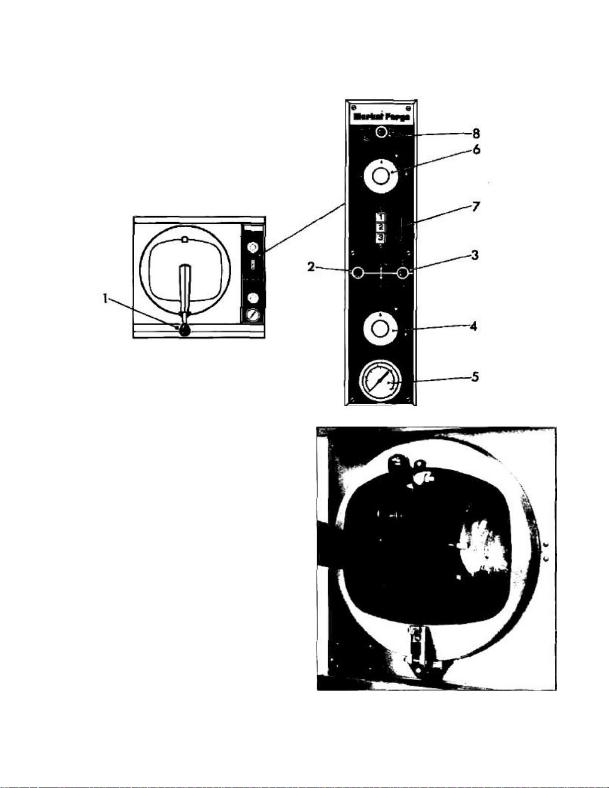
described in Table 3-1. Reference Figure 3-1 for
identification of controls required in the following
procedures.
2.4.1 Initial Control Settings
Before beginning the start -up procedures for the
Dual Matic the instruction plate and service manual
for the steam generator must be consulted and all
start-up procedures completed to supply 15 psi
steam to the steam inlet circuit for the cooker.
1. All steam generator controls are in the operating
mode and 15 psi steam is applied to the Dual
Matic inlet plumbing.
2. Both cooker timers (Figure 3-1; 4, 6) are in the
OFF position.
3. Cooker compartment is empty of all information
materials and the door is open.
2.4.2 Cooker Check-Out
2.4.2.1 Pressure Cooking Mode (Figure 3-1)
1. Close cooker compartment door, being certain
latch handle (1) is securely engaged.
2. Place selector switch (2) in PRESSURE COOKING (down) position.
3. Set 60-MINUTE Ti mer dial (4) at "4-minute"
position. Indicator light (3) will turn on. Operation
is correct if operating pressure (13-15 psi
indicated on gauge) is attained before 4-minute
time elapses. Indicator light will turn off and
buzzer will sound at end of 4-minute period.
2-1
Page 7

2-2 DUAL MATIC STEAM COOKER
4. Turn timer dial (4) to OFF. Buzzer will shut off.
5. Open cooking compartment door.
4. Repeat #3 to check 2-Pan operation at 4 1/2
minute duration and 3-Pan operation at 5 1/2
minute duration. (Timer accuracy ± 5%)
2.4.2.2 Safety Valve (Figure 3-1)
5. Open cooking compartment door.
1. Close cooker compartment door, being certain
latch handle (1) is securely engaged.
2. Place selector switch (2) in PRESSURE (down)
position.
3. Set 60-MINUTE Timer dial (4) to "4-minute"
setting. Pressure gauge (5) will indicate a pres sure rise.
4. Pull out on SAFETY VALVE knob (8). If safety
valve is operating correctly, the pressure will drop
sharply in response to release of steam from
compartment.
5. Release SAFETY VALVE knob (8). Safety valve
should close allowing pressure to rise again.
6. Turn 60-MINUTE Timer dial (4) to OFF position.
7. Open cooking compartment door.
2.4.2.3 Pressureless Cooking Mode (Figure 3-1)
1. Close cooking compartment door, being certain
latch handle (1) is securely engaged.
2. Place selector switch (2) in PRESSURELESS
COOKING (up) position.
3. Set 10-MINUTE Timer dial (6) to "1-minute" and
press 1-PAN push button (7). Operation is correct
if indicator light (3) lights and steam is passed
into cooker and continuously exhausted for a
period of 3^ minutes. At end of cycle buzzer will
sound and indicator light will turn off. (Timer
accuracy ± 5%)
2.4.2.4 Door Shut-Off Switch (Figure 3-1)
1. Close cooking compartment door, being certain
latch handle (1) is securely engaged.
2. Place selector switch (2) in PRESSURELESS
COOKING (up) position.
3. Set 10-MINUTE Timer dial (6) to "1-minute" and
press 1-PAN push button (7). Inlet valve will
open allowing steam to pass through cooking
compartment.
4. With cooker in operation lift door handle (1) and
open door slightly. If operation is correct, inlet
valve will close stopping steam flow into cooker.
Timer will continue to run with indicator light on.
5. Close door and secure latch. Inlet valve will open
for remainder of timed cycle.
6. Return 10-MINUTE Timer dial (6) to OFF
position and open cooker door.
2.4.3 Shut-Down Procedure
No shut-down procedure is required for the Dual
Matic except to check that both timer dials (4, 6) are
in the OFF position and the compartment door is
open. Consult the steam generator instruction plate
and complete the generator shut down procedure.
NOTE
Before final check-off of the Dual Matic/
Generator system for use in cooking, generator
start-up and shut -down must be completed two
more times to insure cleanliness and proper
operation.
S2124
Page 8

SECTION 3 OPERATION
3.1 OPERATING CONTROLS AND INDICATORS
All of the controls required to operate the Dual
Matic are listed in Table 3-1, together with a short
functional description of each. Figure 3-1 shows the
physical location of each control and indicator.
3.2 OPERATING PROCEDURES
The Dual Matic may be used as either a pres sureless steam cooker which defrosts and cooks
frozen food, or as a steam pressure cooker to cook
fresh and defrosted foods. Instructions for operation
in either cooking mode are included in this section.
Consult Test Kitchen Bulletin #54 for detailed
cooking information.
3.2.1 Steam Source Operation
The Dual Matic is supplied mounted on a cabinet
containing either a steam generator or controls for
direct connected steam. Manual controls are ac cessed by opening the cabinet door. Start up procedure for the steam source is completed once
before each daily operating period of the cooker. (For
steam generators see instruction plate.)
3.2.2 Preheating
Before each initial operation of the cooker, and at
any other time when the cooking compartment is
cold, a 3-minute preheating period is required. To
preheat the cooker put steam source into operation
and proceed as follows:
1. Close cooking compartment door and lock
securely in place by pressing down on latch
handled).
2. Place cooking mode selector switch (2) in the
PRESSURE COOKING position.
3. Set 60-MINUTE timer (4) to "3-minute" setting.
4. Turn off buzzer which sounds to indicate
cooking is complete by setting 60-MINUTE
timer dial (4) to OFF position.
5. Allow pressure to return to "0-PSI" (5). Open
door by pulling up on latch handle (1). Allow
remaining vapor to escape before raising door
to full open position.
3.2.3 Pressureless Steam Cooking
Before loading the cooker, be sure compartment
is hot. See 3.2.2 for preheating instructions.
1. Slide pans of food into cooking compartment pan
supports.
2. Close cooking compartment door and push down
on latch handle (1) to engage lock.
3. Place cooking mode selector switch (2) in
PRESSURELESS COOKING (up) position.
4. Set 10-MINUTE timer (6) to required cooking
time.
5. Press pan selector button 1, 2 or 3 (7) coinciding
with the number of pans loaded in cooker.
NOTE To activate control circuit, the timer must be
set first, then the pan selector button pushed.
6. Turn off buzzer which sounds to indicate cooking
is complete by setting timer dial (6) to the OFF
position.
7. Open door by pulling up on latch handle (1).
8. Unload by sliding pans of food from pan supports,
taking care to avoid hitting compartment opening.
3.2.4 Pressure Cooking
Before loading the cooker be sure compartment
is hot. See 3.2.2 for preheating instructions.
1. Slide pans of food into cooking compartment pan
supports.
2. Close cooking compartment door and push down
on latch handle (1) to engage lock.
3. Place cooking mode selector switch (2) in
PRESSURE COOKING (down) position.
4. Set 60-MINUTE Timer (4) to required cooking
time.
5. Turn off buzzer which sounds to indicate cooking
is complete by setting 60-Minute timer dial to the
OFF position.
6. Allow pressure to return to "0-PSI" (5). Open door
by pulling up on latch handle (1). Allow remaining
vapor to escape before raising door to full open
position.
3-1 S2124
Page 9
3-2 DUAL MATIC STEAM COOKER
7.
Unload by sliding pans of food from pan sup
ports,
Figure
3-2.
Pan Support Removal
Figure 3-1. Dual Mafic Controls and Indicators
taking care to avoid hitting compartment opening.
3.2.5 Shut-Down Procedure
No shut -down procedure is required for the Dual
Matic except to check that both timer dials (4, 6) are in
the OFF position, and the compart ment door is open.
When all cooking has been completed for the day the
steam source must be shut off. (For steam generators
see instruction plate.)
3.3 CLEANING
After each period of daily operation (more
frequently as required to maintain cleanliness), the Dual
Matic should be thoroughly cleaned by completing the
following steps.
1. Remove left and right side pan supports (Figure 3-2)
by lifting front up and forward to disengage from
mounting studs. Wash with detergent, rinse, and set
aside for reassembly.
S2124
Page 10

OPERATION 3-3
pressed.
set.
TABLE 3-1 CONTROLS AND
INDICATORS (See figure 3-1)
Figure 3-1 Ref. Description Function
1 Latch Handle Secures cooker door in closed position. Lift to open.
2
Selector Switch
PRESSURELESS
COOKING/PRESSURE
The cooking mode selector switch. Placed in up
position for pressureless cooking; down position for
pressure cooking.
3 Indicator Light (Red) Indicates when lit that cooker is in operation.
4
60-Minute Timer
(Pressure cooking)
5 Pressure Gauge
Controls pressure cooking mode cycle duration. Time
manually preset from 0-60 minutes.
Indicates steam pressure (psi/Kg/cm2) inside cooker
chamber during pressure cooking mode of operation.
Controls pressureless cooking mode cycle duration in
6
10-MinuteTimer
(Pressureless Cooking)
conjunction with pan selector buttons. Time manually
preset from 0-10 minutes before selector button
Compensates for cooking time differential between 1, 2
7
Pan Selector
Buttons
1/2/3
or 3 pans of food loaded into the compartment for
pressureless mode. Button coinciding with number of
pans loaded is pressed after the 10-MINUTE timer is
Steam release safety valve opens automatically in the
8
Pressure Release Knob
(Safety valve)
unlikely event that a malfunction causes ex cessive
steam pressure in compartment. Pull out on knob to
operate manually.
2. Wash cooking compartment interior using mild nonabrasive water. Rinse and dry thoroughly.
CAUTION
Failure to wash compartment may result in pitting
of the aluminum surfaces. Use only mild detergent
suitable for use with aluminum.
3. Replace pan supports in compartment and leave door
open.
S2124
Page 11

SECTION 4 PRINCIPLES OF OPERATION
4.1 GENERAL
The Dual Matic Steam Cooker consists of a
cooking compartment into which pans of food are
loaded through an inward opening door. The
compartment is fitted with electrically controlled
steam circuits to apply steam in either the pressure or
pressureless methods and for the duration selec ted
by the operator. The principles of operation in this
section include an explanation of steam and electrical
circuits as well as pressure cooking and pressureless
cooking operation.
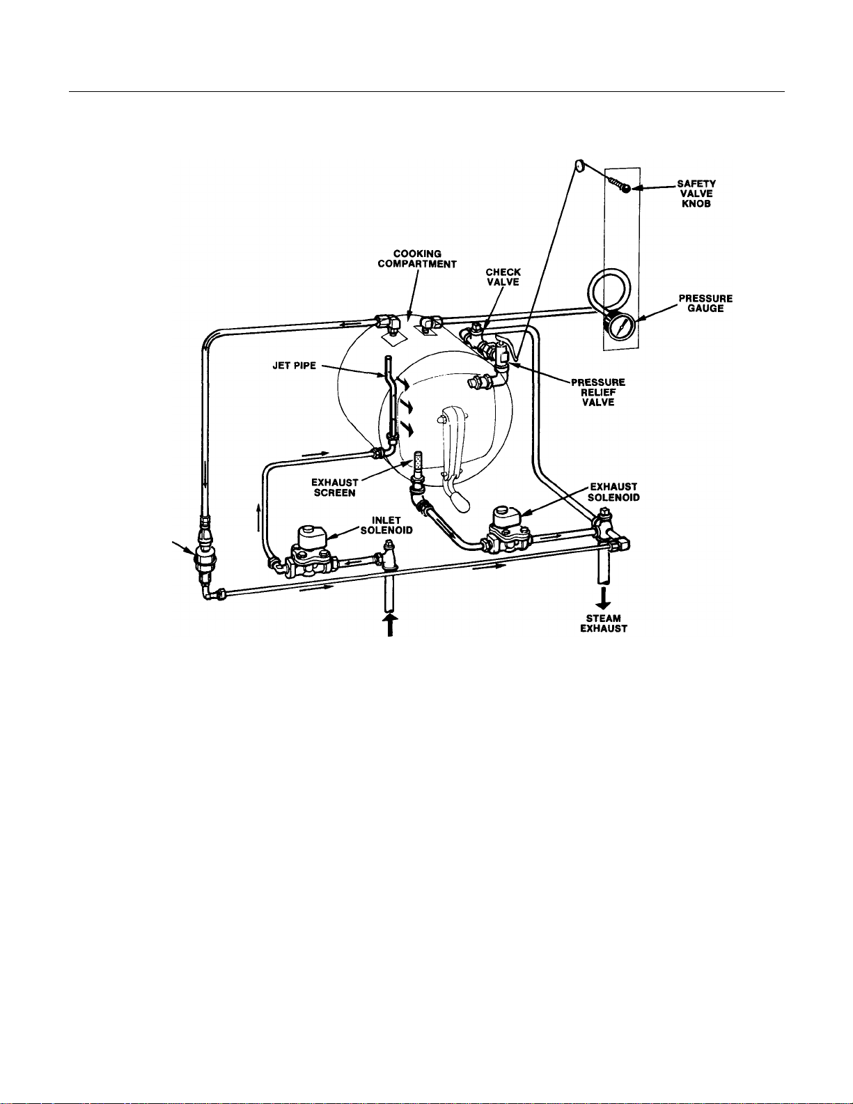
4.2 STEAM CIRCUITS
The steam circuits consist of the piping, solenoid
valves, steam trap, and safety valve required to
provide controlled steam application to the cooking
compartment. A simplified diagram of these circuits is
shown in figure 4-1.
NOTE Figure 4-1 is strictly a pictorial schematic
diagram and is not intended to show the actual
configuration of the circuits. All components are
shown in correct relationship with each other.
However, the diagram does not show their actual
locations or position within the cooker.
As shown in the diagram, steam inlet and ex haust connections are normally connected at the
factory directly into a steam generator on which the
cooker is mounted. The generator is equipped to
supply constant, regulated steam at 14-15 psi. Steam
exhaust is directed into the generator drain system
where it is condensed to water prior to entry into the
building drain system.
Both steam inlet and exhaust lines are equipped
with solenoid valves which are operated by the
electrical control circuit. Both are two-position valves
— the inlet valve normally closed, the ex haust valve
normally open. The inlet valve is opened whenever
the control circuit is activated in either the pressure or
pressureless modes. The exhaust valve is closed
only when the control circuit is activated in the
pressure mode.
4.2.1 Steam Inlet Line
A steam supply line is plumbed from the
generator output to a 1/2" IPS elbow fitting con
nected to the input side of the steam inlet solenoid
valve. At all times when the cooker is not in operation the valve remains closed to prevent steam from
entering the inlet line. During operation the inlet
solenoid valve is opened by activation of the control
circuit. Steam at 15 psi enters the 1/2" line
connected to a coupling in the bottom rear of the
cooking compartment. A jet pipe mounted in the
coupling inside the compartment directs steam
uniformly throughout the interior. Steam continues to
enter the compartment in this manner until the
control circuit closes the solenoid valve.
4.2.2 Steam Exhaust and Drain Lines
Steam exhaust and compartment drainage are
drained from the cooking compartment by a single
line connecting with the steam generator drain
system. A perforated cylindrical strainer mounted inside the cooking compartment at the bottom allows
steam, condensation and cooking drainage to enter
the exhaust line. The line connects to the inlet side
of the exhaust solenoid valve. Except when the valve
is closed by the control circuit, activated in the pres sure mode, exhaust and drainage pass through the
valve into the 3/4" drain line to a waste outlet 'T.
Drainage passes from the cooker into the drain
system of the steam generator.
4.2.3 Pressure Safety Line
A branch of the drain and exhaust line provides
pressure overload protection for the cooking compartment in the unlikely event of equipment malfuntion. The inlet side of a pressure relief valve is
connected with the compartment through a coupling
in the right side. Pre-set to open automatically at
pressures in ex cess of 15 1/2 psi, the valve may
also be operated manually for test purposes by
pulling out on a knob mounted on the control panel.
The knob is connected by a steel cable and suitable
sheaves to the manual release lever at the top of the
valve. The lever is spring-loaded to return to the
closed position when the knob is released.
When the safety valve is opened, steam is allowed to pass into a 3/4" line connected to a sideoutlet T' fitting in the drain line. A check valve
mounted between the safety valve and the T' fitting
prevents back-flow from the drain line.
rev. 3/78 4-1 S2124
Page 12
4-2 DUAL MATIC STEAM COOKER
STEAM
TRAP
STEAM IN
Figure 4-1. Pictorial Diagram — Steam Circuits
4.2.4 Evacuation Line
A separate line between the cooking compart -
ment and the drain provides for evacuation of air
during cooking in the pressure mode. An elbow
fitting mounted into the top of the compartment is
connected through a 1/4" ID tubing line and suitable
fittings to the inlet side of a steam trap. The trap
functions as a chamber evacuator to eliminate air
which passes into it from the cooking compartment.
It is a thermostatically operated valve device preset
to open automatically when air, vapor, or
condensate at temperatures lower than 240° F
enters. The trap closes automatically when steam
above 240° F enters. Discharge from the trap
passes into a %" ID line connected to the waste
outlet "T" of the drain line.
S2124
4.2.5 Pressure Indicator Line
A pressure gauge mounted in the control panel
constantly monitors the steam pressure inside the
cooking compartment. Connection is made through a
1/8" IPS tubing connected to a compression fitting at
the top of the compartment.
4.3 ELECTRICAL CIRCUITS
The electrical circuits of the cooker control the
power to activate timer motors and energize solenoid
operated valves and circuits which in turn control
application of steam to the cooking compartment. The
cooker operates on 120V, 2 amp 60 Hz (50 Hz on
special order) electrical service connected to all
circuits from a 2-pole terminal block mounted to the
cooker frame inside the
Page 13

PRINCIPLES OF OPERATION
4-3
front cover panel. Power input to the terminal block is
connected at the factory from the elec trical circuits of
the steam generator on which the cooker is mounted.
Power is supplied to the control circuit at all times
when the shut -off device for the generator/cooker
system (supplied by the user) is in the ON position.
dial through a gear reduction and clutch mechanism.
The timer dial is manually set for any interval of
operation from 0 to 60-minutes as read on the calibrated dial face. The manual rotation of the dial
moves the common element of the timer switch from
the neutral position to the contact which connects with
pressure mode controls and energizes the timer
motor. When power is applied to the motor, the dial
4.3.1 Control Circuit Components
The control circuit is shown in pictorial diagrams in
figures 4-2 and 4-3. A brief description of the electrical
circuit elements follows.
rotates until the indicator dart coincides with "0minutes." At this point the common element of the
timer switch is transferred to a second contact,
interrupting the circuit to the timer motor, solenoid
valves and indicator light, and applying 120-volts to
the buzzer. Contact to the buzzer circuit remains
4.3.1.1 Selector Switch. The selector switch is a
double-pole, double-throw, two-position switch
(PRESSURELESS COOKING/PRESSURE COOKING). When the switch is in the PRESSURELESS
position those control circuits required for cooker
operation as a free vented system are connected.
Operation begins only after the 10-MINUTE timer dial
is set followed by pressing a pan selector push button.
When the switch is in the PRESSURE position those
circuits required for cooker operation as a pressure
system are connected. Operation begins when the 60MINUTE timer is set.
closed until the dial is manually turned to the OFFposition, returning the common element of the timer
switch to the neutral position.
4.3.1.5 10-Minute Timer. The timer operates in the
same manner as the 60-MINUTE timer but with a
maximum time setting of 10 minut es. The manual
motion of setting the timer dial moves the common
element of the timer switch from the neutral position
to the contact which connects with pressure-less
mode controls, the timer motor and the pan-selector
push-button switch. The timer motor is activated only
after the push button timer has "timed out." The
remainder of operation is the same as for the 60-
4.3.1.2. Indicator Light. The indicator light is
minute timer.
connected into both the pressure and pressureless
cooking mode circuits. It remains lighted (red) at all
times when either the 60-MINUTE timer, or the 10MINUTE timer and the push-button timer are set. It
turns off at the end of the timed cooking duration.
4.3.1.6 Push -Button Timer (pan selector). The
Timer is a three-button solid state capacitor discharge
timing device powered by a separately mounted
120V/36V step-down transformer. The switch
functions to compensate for the alteration in cooking
time associated with cooking 1-pan (2 1/2 minutes), 2-
4.3.1.3 Door Interlock Switch. The interlock switch is
a single pole, two-position, microswitch with normally
open contacts. The switch lever is operated by an
actuating pin mounted in the door latch assembly.
When the door is open the pin remains retracted with
the switch contacts in the normally open position.
When the door latch is engaged to secure the door,
the actuating pin is moved against the switch lever to
pans (3 1/2 minutes), or 3-pans (4 1/2 minutes) of
food in the pressureless mode. When a button is
pressed a light inside is lit and the button is held in the
depressed position by a latching device. Contacts to
externally controlled circuits are closed and internal
timer circuits energized. At the end of the timed
duration (plus the 10-MINUTE timer setting) a
solenoid operates to release the latching device.
close the contacts. Connected into the circuit with the
steam inlet valve, the door switch acts as a protective
device to interrupt valve operation unless the door is
closed.
4.3.1.7 Buzzer. The buzzer is an alarm device which
operates by oscillation of a striker against the core of
an electromagnet. When either the 60-MINUTE or 10-
MINUTE timer dials reach "0-minutes" the buzzer coil
is energized to sound the buzzer. Movement of either
4.3.1.4 60-Minute Timer. The timer contains a 120volt synchronous motor which drives a timing
timer dial to the OFF position opens the contact to the
buzzer coil to shut it off.
S2124
Page 14

4-4 DUAL MATIC STEAM COOKER
4.3.2 Pressure Cooking Operation
When the mode selector switch is placed in the
PRESSURE COOKING position one set of contacts
closes to connect the circuit to the open switch
contacts of the 60-MINUTE timer. A second set of
selector switch contacts close to connect a circuit to
the indicator light and the door interlock switch. The
compartment door is shut, closing the normally open
contacts of the door interlock switch, to connect the
circuit to the coil of the steam inlet va lve. At this
point the cooker is not operating, and all other
components in figure 4-2 are in the open position.
3. 120-volts is applied through the closed contacts
of the door interlock switch to the coil of the
normally closed steam inlet solenoid valve to
open it.
4. The circuit is completed to the indicator light
(red).
5. 120-volts appears across the primary windings
of the push button timer transformer even
though the 36-volt secondary current is not
required.
6. 60-MINUTE timer dial rotates until the indicator
dart coincides with the"0-minute" position. The
common element of the timer switch is tripped,
breaking the circuit to pressure mode
components and transferring it to a second
contact position (1-4). The timer motor is
opened to stop dial rotation.
7. 120-volts is removed from the exhaust valve and
inlet valve coils, and the indicator light.
8. 120-volts is applied to the buzzer coil to produce
an audible signal.
9. Timer dial is manually rotated to the OFF position by the operator. The common element of the
timer switch is transferred from the secondary
contact position to the neutral position, removing
120-volts from the buzzer coil. 10. The cooker
remains off until the 60-MINUTE timer dial is
reset.
4.3.3 Pressureless Cooking Operation
When the mode selector switch is placed in the
PRESSURELESS COOKING position a single set
of contacts close to connect the circuit to the open
TRANSFORMER
NOTE: All CONTROLS SHOWN IN OPERATING
POSITION FOR THE PRESSURE MODE
Figure 4-2. Pictorial Diagram, Electrical Circuits —
Pressure Cooking Mode
The dial of the 60-MINUTE timer is turned by the
operator to the required cooking interval, and the
following sequence of events occurs:
1. Switch (1-3) contacts of the 60-MINUTE timer
close to place 120-volts into the circuit for all
pressure mode electrical components. The timer
motor begins to operate for the set duration.
2. 120-volts is applied across the coil of the normally
open steam exhaust solenoid valve to close it.
S2124
switch contacts of the 10-MINUTE timer. The
operator rotates the 10-MINUTE timer dial to the
required cooking duration, completing the circuit (1-
3) to the timer motor and the push-button timer. The
compartment door is shut, closing the normally
open contacts of the door interlock switch to
connect the circuit to the coil of the steam inlet
solenoid. At this point the cooker is not operating
and all other components in figure 4-3 are in the
open position.
One of the three buttons of the push-button
timer is pressed by the operator and the following
sequence of events occurs:
1. The button is illuminated and held in the
depressed position. Contacts in the button close
the circuit to the internal timer circuits and apply
120-volts into the circuit for pres -sureless mode
electrical components and the transformer.
2. 120-volts is applied to the primary winding of the
120 V./36v. transformer to energize the timer
circuit.
Page 15

PRINCIPLES OF OPERATION 4.5
3. 120-volts is applied through the closed contacts of
the door interlock switch to the coil of the
normally closed steam inlet solenoid valve to
open it.
4. The circuit is completed to the indicator light (red).
5. The push-button timer completes the cycle of
operation for the button pressed, immediately
applying 120-volts to the 10-MINUTE timer motor.
6. Timer dial rotates until the indicator dart coincides
with "0-minute." The common element of the
timer switch is tripped breaking the circuit to
pressureless mode components and transferring
it to a second contact position (1-4). The timer
motor circuit is opened to stop dial rotation.
7. 120-volts is removed from the inlet valve coil and
the indicator light.
8. 120-volts is applied to the buzzer coil to produce
an audible signal. A separate circuit to the pushbutton timer applies a momentary impulse to an
internal solenoid coil to release the timer button,
NOTE: ALL CONTROLS SHOWN IN OPERATING
POSITION FOR THE PRESSURELESS MODE
Figure 4-3. Pictorial Diagram, Electrical Circuits Pressureless
Cooking Mode
open the circuit to the button lamp and to the 10MINUTE timer motor.
9. Timer dial is manually rotated to the OFF position
by the operator. The common element of the
timer switch is transferred from the secondary
contact position to the neutral position, removing
120-volts from the buzzer coil and the circuit to
the push-button timer.
10. The cooker remains off until the 10-MINUTE dial
is reset and a push-button pressed.
S2124
Page 16

SECTION 5 TROUBLE-SHOOTING
lector Switch in PRESSURELESS
5.1 GENERAL
The information in this section is intended to
assist both the operator and service personnel in
locating the general source of problems which may
occur with the Dual Matic. Before following any of
the procedures given in this section, the operator
should be thoroughly familiar with the operating
instructions and the function of all controls which
are described in Section 3. If the problem cannot
be readily corrected, the operator should contact
the nearest Market Forge service agency for
assistance.
5.2 TROUBLE-SHOOTING GUIDES
An operator's trouble-shooting guide for use
TABLE 5-1 OPERATOR'S TROUBLE-SHOOTING
by the Dual Matic operator is given in Table 5-1.
Table 5-2 gives additional, more extensive information for use by service personnel.
5.3 ELECTRI CAL FAULT ISOLATION
Correction of an electrical failure first requires
isolation of the fault to a single circuit or
component. In most cases the nature of the failure
and its effect upon the operation of the Dual Matic
will be sufficient to isolate it to one or more circuit
elements. Table 5-3 is provided as a guide for
isolating electrical faults.
GUIDE
PROBLEM
Probable Cause
1. INDICATOR LIGHT FAILS TO LIGHT
a. Power to Dual Matic off.
b. Se
COOKING position.
c. 60-Minute timer not set.
2. INDICATOR LIGHT FAILS TO LIGHT
a. Power to Dual Matic off.
b. Selector Switch in
PRESSURE COOKING
position.
c. 10-Minute timer not set.
d. Button of Push-Button timer not
depressed.
Remedy
IN PRESSURE COOKING MODE.
Locate external circuit breaker for incoming power and
place in ON position.
Place in PRESSURE COOKING position.
Set 60-Minute timer.
IN PRESSURELESS COOKING MODE.
Locate external circuit breaker for incoming power and
place in ON position.
Place in PRESSURELESS COOKING position.
Set 10-Minute timer (Before pressing pushbutton, d).
Press one of the three buttons (After setting 10-Minute
timer, c). NOTE: Cooker will not operate if push button
is depressed before setting 10-Minute timer.
5-1 S2124
Page 17

DUAL MATIC STEAM COOKER
Locate external circuit breaker for incoming
TABLE 5-1 (cont.)
PROBLEM Probable Cause Remedy
3. STEAM FAILS TO ENTER COMPARTMENT IN EITHER PRESSURE OR PRESSURE-LESS COOKING MODES
WITH INDICATOR LIGHT ON.
a. Compartment door not latched securely. Close door and engage handle in latch.
b. Steam not entering Dual Matic control Check steam supply generator for proper oper plumbing. tion.
TABLE 5-2
GENERAL TROUBLE-SHOOTING GUIDE
PROBLEM Probable Cause Remedy
1. INDICATOR LIGHT FAILS TO LIGHT WITH SELECTOR SWITCH IN PRESSURE COOKING POSITION
AND 60-MINUTE TIMER SET.
a. Power to Dual Matic off.
power and place in ON position.
b. Indicator light burned out. Replace light.
c. Faulty wiring. Inspect condition of wire, and tightness of all
connections. Correct as needed.
d. Faulty Selector Switch. Replace switch. See subsection 5.4.3.
e. 60-Minute timer contact faulty. Replace 60-Minute timer. See subsection 5.4.4 .
2. INDICATOR LIGHT FAILS TO LIGHT WITH SELECTOR SWITCH IN PRESSURELESS COOKING
POSITION AND BOTH 10-MINUTE TIMER AND PUSH-BUTTON TIMER SET.
a. Power to Dual Matic off. Locate external circuit breaker for incoming
power and place in ON position.
b. Indicator light burned out. Replace light.
c. Faulty wiring. Inspect condition of wire and tightness of all
connections. Correct as needed.
d. Faulty selector switch. Replace switch. See subsection 5.4.3.
e. 10-Minute timer contacts faulty. Replace 10-Minute timer. See subsection 5.4.5.
f. Push-Button timer contacts faulty. Replace Push-Button timer. See subsection 5.4.6.
3. PRESSURE COOKING MODE FAI LS TO STOP.
a. Defective 60-Minute timer motor Replace 60-Minute timer. See subsection or
contact. 5.4.4.
b. Defective steam exhaust solenoid Replace valve. See subsection 5.4.8. valve.
Page 18

TABLE 5-2 (cont.)
PROBLEM
Probable Cause
4. PRESSURELESS COOKING MODE FAI LS TO STOP.
a. Defective 10-Minute timer motor or contact. Replace 10-Minute timer. See subsection 5.4.5.
b. Defective Push -Button timer or transformer. Replace Push-Button timer. See subsection 5.4.6.
c. Defective steam inlet valve. Replace valve. See subsection 5.4.8.
5. STEAM FAILS TO ENTER COMPARTMENT IN EITHER COOKING MODE (WITH INDICATOR LIGHT ON).
a. Compartment door not closed. Securely latch door closed.
b. No steam entering Dual Matic steam line. Check steam generator for proper operation.
c. Faulty door interlock switch. Replace switch. See subsection 5.4.7.
d. Faulty inlet solenoid valve. Replace valve. See subsection 5.4.8.
6. STEAM ENTERS COMPARTMENT AT ALL TIMES.
a. Ruptured inlet solenoid diaphragm. Replace valve.
b. Defective or jammed door interlock switch. Clean or replace switch. See subsection 5.4.7.
7. NO STEAM PRESSURE GAUGE READING IN PRESSURE COOKING MODE (WITH INDICATOR LIGHT ON).
a. Insufficient steam input from steam Check generator for 15 psi output and make
generator, necessary adjustment.
b. Faulty pressure gauge. Replace gauge.
c. Faulty steam exhaust solenoid valve. Replace valve. See subsection 5.4.8.
d. Faulty relief valve. Replace valve.
Remedy
8. BUZZER FAILS TO SOUND AT END OF PRESSURE COOKING DURATION (WITH INDICATOR LIGHT OFF).
a. Faulty 60-Minute timer contacts. Replace 60-Minute timer. See subsection 5.4.4.
b. Faulty buzzer. Replace buzzer. See subsection 5.4.9.
9. BUZZER FAILS TO SOUND AT END OF PRESSURELESS COOKING DURATION (WITH INDICATOR LIGHT OFF).
a. Faulty 10-Minute timer contacts. Replace 10-Minute timer. See subsection 5.4.5.
b. Faulty buzzer. Replace buzzer. See subsection 5.4.9.
10. PUSH-BUTTON REMAINS DEPRESSED WHEN BUZZER SOUNDS AT END OF PRESSURELESS COOKING
DURATION.
a. Faulty Push -Button timer solenoid. Replace Push-Button timer. See subsection 5.4.6.
11. IN PRESSURE COOKING MODE COOKING COMPARTMENT FAILS TO REACH COOKING TEMPERATURE.
a. Air in cooking compartment. Replace steam trap.
b. b. Low steam pressure. See item 7.
Page 19

TABLE 5-2 (cont.)
Buzzer fails to sound at end of either Pressure or
button timer fails to reset (button released)
DUAL MATIC STEAM COOKER
PROBLEM
Probable Cause
12. IN PRESSURE COOKING MODE PULL ING OUT
CAUSE PRESSURE DROP.
a. Valve knob cable dissengaged.
b. Defective relief valve.
TABLE 5-3 ELECTRICAL FAULT ISOLATION GUIDE
FAILURE FAULT LOCATION
1. Will not operate in either Pressure or
Pressureless Cooking mode.
2. Operates in Pressure mode but not in
Pressureless mode.
Remedy
ON SAFETY VALVE KNOB FAILS TO
Reconnect or replace cable.
Replace relief valve.
a. Incoming power
b. Selector Switch
c. Wiring
a. Selector Switch
b. Wiring
c. 10-Minute timer
d. Push -Button timer e. Transformer
3. Operates in Pressureless mode but not in
Pressure mode.
a. Selector Switch
b. Wiring
c. 60-Minute timer
4. Exhaust solenoid valve fails to close with
indicator light on in Pressure mode.
5. Indicator light off in either mode.
6. Inlet solenoid valve fails to open but indicator
light is on in either mode.
a. Exhaust solenoid valve coil
b. Wiring
a. Indicator light
b. Wiring
a. Door interlock switch
b. Inlet solenoid valve coil
c. Wiring
7.
Pressureless cooking.
8. Push at completion of Pressureless cooking.
a. 10-or 60-Minute timer contacts
b. Buzzer
c. Wiring
a. 10-Minute timer contacts
b. Push-Button timer
c. Wiring
9. Will not stop operating in Pressure mode. a. 60-Minute timer motor
10. Will not stop operating in Pressureless mode.
a. 10-Minute timer motor
b. Push -button timer
Page 20

TROUBLE -SHOOTING
5.5
5.4 ELECTRICAL TROUBLE-SHOOTING PROCEDURES
Before performing the trouble-shooting proce-
Pressure and Pressureless Cooking modes, or failure
to operate in one mode only. To check the Selector
Switch, proceed as follows:
dures in this section the serviceman must be
familiar with the function of all controls as
described in Section 3 and with the Principles of
Operation described in Section 4.
Electrical trouble-shooting procedures which
follow require access to components and terminals
of the electrical control panels shown in fig. 7-6 and
7-7. Electrical controls are reached by removing
the machine top, lower trim edge, and lower front
panel as described in subsection 6.3.2. Wiring and
terminal locations are shown in figure 5-1.
1. Turn off power to the Dual Matic at external
breaker.
2. Disconnect all five wires (1, 2. 3, 12, 19) from
Selector Switch terminals (figure 5-1).
3. Connect an ohmmeter between the middle
terminal and either one of the outer terminals (A,
B) for one pole of the switch.
4. Operate switch to obtain a reading of zero ohms
on meter when switch is in either PRESSURE
COOKING or PRESSURELESS COOKING
position. If a zero reading cannot be obtained,
5.4.1 Incoming Power
Before trouble-shooting any of the electrical parts
or assemblies, verify that power is being supplied to
the Dual Matic. Incoming power is connected at the
terminal block (figure 7-7,1). With power connected
to the Dual Matic an a-c volt-meter is used to
measure 120 Volts across terminals to lines coded
switch is defective and must be replaced.
5. Move ohmmeter leads to second pole of switch.
6. Repeat Step 4. If zero ohm reading cannot be
obtained, switch is defective and must be
replaced.
7. Remove ohmmeter and replace all five leads on
Selector Switch as shown in figure 5-1.
18 and 19. If power is not present, the connection
to the Dual Mat ic is faulty. If 120 volts is present,
and the cooker will not operate, the fault lies within
5.4.4 60-MINUTE Timer
the electrical circuits of the Dual Matic.
5.4.2 Electrical Inspection
The first step in any electrical trouble-shooting
procedure is a thorough physical inspection of all
wiring connections. To access electrical
components remove the control panel as explained
in subsection 6.3.3.
WARNING
Before removing control panel or checking connections and wiring be sure that the circuit
5.4.4.1. Timer Contacts. Defective timer contacts
will result in failure of the Dual Matic to operate in the
Pressure Cooking mode. If the cooker fails to operate
in the Pressure Cooking mode, but functions
correctly in the Pressureless Cooking mode, the fault
is with the 60-Minute timer contacts or it's wiring.
When this occurs, remove the control panel
(subsection 6.3.3), and proceed as follows:
breaker for incoming power to the Dual Matic is
OFF. When power is supplied all exposed
terminals of the control panel carry 120 volts.
Check all wiring connections by hand to assure
that both ends of all connection points are tightly
secured. Use a screwdriver to tighten connection
points if necessary. Visually inspect all quickdisconnect terminals for evidence or corrosion.
Terminals in this condition should be separated,
cleaned with emery cloth until shiny and tightly
reconnected.
CAUTION
Extreme care must be taken in removing or replacing connections on the push-button timer
P.C. board. Do not pull wires loose from quickdisconnect terminals.
5.4.3 Selector Switch
A defective Selector Switch may be the cause
1. Turn off power to the Dual Matic at external circuit
breaker.
2. Disconnect all four wires (1. 4, 6. 14) from timer
terminals. (See figure 5-1).
3. Connect an ohmmeter between terminal 1 and
terminal 3.
4. Rotate timer dial beyond the 0-MINUTE point (any
setting) to obtain a reading of zero ohms on the
ohmmeter. If zero reading cannot be obtained,
timer contacts are defective and the timer must
be replaced.
5. Move ohmmeter leads to terminals 1 and 4.
6. Rotate timer dial to 0-MINUTE position. (An
audible click indicates correct position). If zero
ohm reading cannot be obtained, the timer is
defective and must be replaced.
S2124
of failure of the Dual Matic to operate in both
rev. 3/78
Page 21

Figure 5-1. Wiring Diagram, Dual Matic
Page 22

TROUBLESHOOTING
5-7
7. Remove ohmmeter and replace all four leads on
timer terminals as shown in figure 5-1.
5.4.4.2 Timer Motor. A defective timer motor will
cause continuous operation in the pressure mode
with the timer dial failing to return to the 0-MIN-UTE
position. If the timer motor fails to turn proceed as
follows:
1. Carefully check motor wire leads (10 and 11) and
tighten loose connections.
WARNING
Use care while working with control panel.
Terminals carry 120 volts.
2. Turn on power to the Dual Mafic.
3. With Selector Switch in PRESSURE COOKING
position, set 60-MINUTE timer dial (any setting
beyond "0-minute"). If operation is correct the
motor will turn the dial dart through an arc toward
"0-minute". If the motor fails to operate, it is
defective and the entire timer must be replaced.
4. Shut off power to the Dual Matic.
5.4.5 10-MINUTE Timer
5.4.5.1 Timer Contacts. Defective timer contacts will
result in failure of the Dual Matic to operate in the
Pressureless Cooking mode. If the cooker fails to
operate in the Pressureless Cooking mode, but
functions correctly in the Pressure Cooking mode, the
fault may be in the 10-Minute timer or its wiring.
When this occurs check the timer contacts in the
same manner as explained for the 60-Minute timer in
paragraph 5.4.4.1. Use an ohm-meter to check
contacts between terminals 1 and 3 and between 1
and 4. Should a reading of zero ohms fail to be
obtained for either, the timer is defective and must be
replaced.
5.4.5.2 Timer Motor.
A defective timer motor will cause continuous
operation in the Pressureless Cooking mode with the
timer dial failing to return to the 0-MINUTE position. If
the timer motor fails to turn proceed as follows:
1. Connect a jumper wire between push-button
timer terminals 4 and 5.
rev. 3/78
2. Connect a jumper wire between terminal 3 on the 10Minute Timer and selector switch terminal connected
to wire 19.
WARNING
Use care while working with control panel. Terminals
carry 120 volts.
3. Set 10-Minute timer dial at 1-MINUTE position.
4. Touch second lead wire to Push -Button timer terminal
5. Motor should begin to operate, returning dial to 0MINUTE position. If not, motor is defective and entire
10-Minute timer must be replaced.
5. Turn off power to Dual Matic.
6. Remove jumper wires and reconnect wires to Push
Button timer terminals.
5.4.6 Push -Button Timer and Transformer
A defective Push -Button timer will result in failure of the
Dual Matic to operate in the Pressureless Cooking mode.
If the cooker fails to operate in the Pressureless mode
and the selector switch operates correctly, the fault may
be in the Push -Button timer or its wiring. When this
occurs consult one of the following paragraphs describing
the nature of the fault.
5.4.6.1 Timer Contacts. If Pressureless Cooking fails to
begin when all controls are set correctly, the fault may be
in the contacts of the Push -Button timer. Proceed as
follows:
1. Turn off power to the Dual Matic.
2. Disconnect the four wires (5, 3, 17, 13) to terminals 1
and 2 (See figure 5-1).
CAUTION
Extreme care must be taken in removing or replacing
connections on the push -button timer P.C. board. Do
not pull wires loose from quick-disconnect terminals.
3. Connect an ohmmeter between terminals 1 and 2.
4. Depress one of the three pan selector buttons to
obtain a reading of zero ohms on the meter. Depress
each of the other two buttons to obtain a zero ohm
reading for each. If a zero ohm reading cannot be
obtained for any button, the Push -Button timer is
defective and must be replaced.
5. Remove ohmme ter and replace all four leads on
terminals 1 and 2 as shown in figure 5-1.
5.4.6.2 Timer Circuit/Transformer.
Should the Pressureless Cooking mode fail to stop
once begun, the fault may be in the internal timer
circuits or
S2124
Page 23

5-8 DUAL MATIC STEAM COOKER
the transformer for the Push-button timer. When this
occurs proceed as follows:
WARNING
Use care while working on control panel.
Terminals carry 120 volts.
1. Turn on power to Dual Matic, place Selec tor
Switch in PRESSURELESS COOKING position,
set 10-Minute timer dial (any setting beyond "0-
minute"), and depress 3-PAN push-button.
2. Connect an a-c volt meter between secondary
terminals GR (green) and GR (green) of the
transformer to obtain a 36 volt reading on the
meter. If a reading of 36 volts cannot be obtained, the transformer is defective and must be
replaced.
3. Allow Push-button timer duration to elapse (3PAN button = 41/2 minutes), then proceed with
steps 4 and 5.
4. Disconnect 10-Minute timer motor lead (no
number) from terminal 4 of the Push-Button
timer.
5. Connect an a-c volt meter between terminals 1
and 4 of the Push-Button timer to obtain a 120
volt reading on the meter. If a reading cannot be
obtained, the Push-Button timer is defective and
must be replaced.
6. Turn off power to the Dual Matic.
5.4.6.3 Timer Solenoid Circuit. A defective PushButton timer solenoid will prevent the depressed
push-button from being released when the 10-Minute
timer has "timed-out" to 0-MINUTE. If the button fails
to release, proceed as follows:
WARNING
Use care while working on timer on control
panel. Terminals carry 120 volts.
1. Install a jumper wire from Push-button terminal 3
to the Selector Switch terminal connecting with
wire 2.
2. Place Selector Switch in PRESSURELESS
COOKING position.
3. Turn on power to the Dual Matic.
4. Depress the 1-PAN button and allow 1 1/2 minute
duration to elapse. Operation is correct if the
solenoid energizes to release the depressed 1PAN button. If not, Push-Button timer is
defective and must be replaced.
S2124
5. Disconnect power to Dual Matic and remove
jumper wire.
5.4.7 Door Interlock Switch
The only malfunction which results from a
defective cooker compartment door switch is
failure of the normally closed inlet solenoid valve to
open. If steam does not enter the compartment
when the door is closed, and the door latch is
securely engaged with all controls set for either
Pressure or Pressureless Cooking, the fault may
be in the door interlock switch. Proceed as follows:
1. Turn off power to the Dual Matic.
2. Disconnect the two wires to the door switch
terminals (See figure 5-1).
3. Connect an ohmmeter between the two terminals of the switch.
4. Depress the door latch plunger, closing the
normally open switch contacts to obtain a
reading of zero ohms on the meter. If a zero
reading cannot be obtained, the switch is
defective and must be replaced.
5. Remove the ohmmeter and replace the two
leads on switch terminals (See figure 5-1).
5.4.8 Solenoid Valves
When either the inlet or exhaust solenoid valves
fail to operate, the fault may be a defective coil. A
defective coil is found using an a-c volt meter to
check the voltage at the coil wire terminals, with
the Dual Matic operating in the Pressure Cooking
mode. If voltage of 120 volts is present the fault is
the coil. Defective valve coils are not separately
replaceable, requiring complete valve replacement.
5.4.9 Buzzer
If the buzzer does not sound at the termination of
either the Pressure or Pressureless Cooking
modes (timer dial returned to "0-Minute" position),
the fault may be a defective buzzer. Buzzer
operation is verified using an a-c volt meter at
buzzer coil connections (permanently soldered),
with input power on. Selector Switch in the
PRESSURE COOKING position and the 60-Minute
timer dial at the "0-minute" position. If voltage is
120 volts, the fault is in the buzzer which must be
replaced. If 120 volts is not present, the fault is in
the wiring or control components (60-Minute timer.
Selector Switch).
5.4.10 Indicator Light
If the Dual Matic functions correctly with the
single exception that the indicator light fails to
rev. 3/78
Page 24

TROUBLE-SHOOTING
light during operation, the fault is a defective indicator
light. A "burned-out" or defective light is verified by
using an a-c volt meter at the leads (terminal strip
terminals 1 and 7), with input power on. the Selector
Switch in the PRESSURE COOKING position and the
60-Minute timer dial set (any setting beyond "0minute"). If 120 volts is present the fault is in the
indicator light and requires replacement. If 120 volts is
not present the fault is in the wiring or control
components (Selector Switch, 60-Minute timer).
5.4.11 Wiring
All of the electrical components of the Dual Matic
(Selector Switch, 60-Minute timer, 10-Minute timer,
Push-Button timer/transformer, solenoid valves,
buzzer and indicator light) are connected to each ot her
by wiring shown in Figure 5-1. If all of the electrical
components are operating correctly (and the incoming
power has been checked), but the cooker fails to
operate in either the Pressure or Pressureless modes,
the fault lies in the wiring.
Figure 5-1 is a wiring diagram which shows all
terminals and interconnections within the electrical
circuits. All numbered terminals are identified and all
leads number coded as shown. Connections can be
easily removed. Figure 5-2 shows the same information schemat ically and is an aid in isolating
circuits for testing.
Using an ohmmeter, wiring continuity between the
connections shown on the wiring diagram (figure 5-1)
are readily verified. This is best done in stages,
removing only those wires required for each continuity
check. As each lead is replaced it should be checked
for evidence of corrosion and cleaned if necessary. All
leads must be tightly attached so as to provide a good
electrical connec tion.
Figure 5-2. Schematic Diagram, Dual
Matic
S2124
Page 25

SECTION 6 MAINTENANCE
6.1 GENERAL
This section contains both preventive and
corrective maintenance information. Preventive
maintenance may be performed by maintenance
personnel at the establishment in which the cooker
is installed. It is recommended that user personnel
never attempt to make repairs or replacements to
the equipment without the assistance of authorized
service. Assistance in service methods or a current
Directory of Authorized Service Agencies may be
obtained from Market Forge. (See subsection 1.3).
6.2 PREVENTIVE MAINTENANCE
A good preventive maintenance program begins
with the daily cleaning procedure described in
subsection 3.3. Additional preventive maintenance
operations are presented in this section. In establishments which employ full-time maintenance
personnel, the tasks described can be assigned to
them. For other installations, tasks requiring
mechanical or electrical experience should be
performed by an authorized service agency.
Table 6-1 sets forth minimum preventive maintenance procedures which must be completed
periodically to assure continued trouble-free
operation of the Dual Matic.
6.2.1 Door Disassembly and Cleaning
The door assembly must be removed from the
cooker compartment for weekly cleaning. Though
no tools are needed, care in following procedure is
necessary to insure that the door will pass through
the compartment opening.
1. With cooking compartment door open, lift pan
supports up and forward to dissengage from
mounting studs. Remove from compartment as
shown in figure 3-2.
TABLE 6-1 PREVENTIVE
MAINTENANCE
Frequency Procedure
Daily 1. Cleaning — Remove pan supports and thoroughly wash and rinse cooker compart ment
interior with mild soap or aluminum cleaner. Leave door open when cooker is not in use.
See subsection 3.3.
CAUTION: Do not use strong detergent or abrasive cleaners. Pitting of aluminum interior
will result.
Weekly 1. Door Assembly Cleaning — Remove cooker door assembly as explained in sub-
section 6.2.1 and wash thoroughly with detergent and water. Inspect door gasket and
replace if worn. Exercise care in reassembly and check for tight door sealing in closed
position.
NOTE: Care must be exercised in following disassembly instructions. Door passes
through compartment opening with ease when procedure is followed in
sequence.
2. Safety Valve Check — With Compartment under pressure pull out on safety valve
knob to allow steam to escape. Pressure shown on gauge will drop sharply in response to
valve opening as explained in subs ection 6.2.2.
6-1 S2124
Page 26

Figure
6-2.
Door Removal
Disengage left and right ends of door seat spring by
counter-acting the force of the door lift spring with
one hand while disengaging studs with the other
hand (figure 6-1).
DUAL MATIC STEAM COOKER
5. Inspect door gasket for cleanliness and wear. If
food soil has become lodged behind the
gasket or the gasket is torn, push it off
perimeter of door and clean or replace as
needed (figure 6-3). A gasket which is stuck
to the door is easily removed by first soaking
the entire door in hot soapy water.
Figure 6-1. Door Spring Disengagement
Push door lift springs to the rear and off studs.
Rotate the door assembly out through the door
opening, door handle first, as shown in figure 6-2.
Figure 6-3. Gasket Removal
NOTE
To assure a pressure seal, the gasket
must be cleaned of soil and scale, and
be free of breaks.
6. Replace gasket on door and reassemble door
assembly in compartment. Open and close
door several times to check for correct
operation and tight seal of door in closed
position. See paragraph 6.3.1.2 to adjust door
seal tension.
6.2.2 Safety Valve Check
The safety valve is a protective device which
automatically relieves excessive pressure (above
15 1/2 psi, Ikg/cm2) in the unlikely event of equipment malfunction. Manual opening of the valve is
also possible and should be done once a week to
assure that the valve is clear and mechanically
sound.
1. Place cooker into operation in the pressure
mode (subsection 3.2.4) and allow pressure
to build up to about 15 psi.
2. Pull out on safety valve knob (figure 3-1, 8). A
sharp drop in pressure indicated by the
pressure gauge verifies correct manual valve
functioning and clears exhaust passage. If
pressure fails to drop, shut cooker off by
returning 60-Minute
Page 27

MAINTENANCE 6-3
timer dial to the OFF-position and consult
section 6.3.4 for replacement procedure.
NOTE
Steam emitted by valve is directed into the
drain and can neither be heard nor seen.
can be made pliable by first soaking it in hot soapy
water. Remounting the door in the compartment
completes the replacement.
NOTE
The critical function of the door seal makes it
imperative that the gasket be in good
3. Return 60-Minute Timer dial to the OFF-position.
condition. For this reason it is recommended
that at least one spare gasket be kept at all
6.2.3 Door Fulcrum Cleaning & Lubrication
times.
The door fulcrum assembly located under the
door opening includes the door latch anchor, the
door switch, switch actuating pin and the fulcrum
adjustment screw. These parts are shown in figure
7-5.
Periodic unscheduled cleaning of the actuating
pin (15) with detergent -water solution will ensure
trouble free operation. The actuating pin and its
guide must be free of food particles, with pin motion
easy and unrestricted.
The anchor is equipped with a bronze roller
bearing (7) which engages the hooked door latch.
The entire roller assembly is shown as item (10) in
figure 7-5. The roller must be cleaned periodically to
insure free-moving operation. Should accumulated
dirt or food interrupt normal rolling, detergent -water
solution should be used to free it. Cleaning should
be followed by lubrication using graphite or other
dry lubricant.
6.3.1.2 Door Seal Tension Adjustment. An
adjustment screw is built into the door anchor and
fulcrum assembly to allow compensation for
normal variation in gasket thickness caused by
wear. The adjustment screw is shown in figure 6-
4. If steam escapes from around the door, sealing
tension against the door opening can be increased
by loosening the 1/4-20 jam nut and turning the
socket head adjustment screw counterclockwise
with an allen wrench. Installation of a replacement
door gasket may result in excessive door latching
tension and require clockwise adjustment of the
screw. Trial and error will achieve the screw
adjustment which both seals the door against the
compartment opening yet allows door latching with
only moderate force applied to the handle. The
final position is set by holding the cap screw with
an allen wrench while tightening the 1/4-20 jam
nut.
6.3 REPAIR AND REPLACEMENT
Section 7 of this manual contains a listing of all
replaceable parts and associated exploded views of
the Dual Matic. In most cases disassembly procedures will be obvious from the exploded views.
Illustrated disassembly and assembly instructions
follow for procedures which are not readily
apparent.
6.3.1 Door Assembly
The door assembly consists of the door latch
and the latch fulcrum assembly. All parts are replaceable as shown in figures 7-3, door assembly;
Figure 7-4, door latch; and figure 7-5, door fulcrum
and switch.
6.3.1.1 Gasket Replacement. The door gasket
(figure 7-3, 5) is readily replaced by first removing
the door assembly from the cooking compartment
as explained in subsection 6.2.1. The worn gasket
is removed in the same manner as described for
cleaning and a replacement substituted. A new
gasket which is difficult to stretch onto the door
Figure 6-4. Door Seal Tension Adjustment
6.3.1.3 Door Lift Spring Replacement. Should
either spring bec ome damaged, it is necessary to
replace both left and right springs as a set (figure
7-3). The door assembly is removed from the
cooking compartment as explained in subsection
6.2.1. Springs are installed by removing spring
bearings (1), screws (3), and worn springs (2A,
2B) and mounting replacements. Springs are
marked
S2124
Page 28

6-4
DUAL MATIC STEAM COOKER
with tabs indicating the left and right side replacement springs for installation on the appropriate side
as viewed from the front of the compartment.
6.3.2 Exterior Panel Removal
Access to all internal plumbing assemblies is
from the top and front of the Dual Matic cabinet.
Whenever internal repairs or replacements are
required, the top panel and the front trim and lower
panel must first be removed. These parts are
shown in figure 7-1. The following procedure is
required for removal of exterior panels.
1. Raise the cooking compartment door.
2. Remove the three truss head screws (5) in the
lower front panel (4), and the two round head
screws (3) and washers (2) at each end of the
lower front trim assembly.
3. Loosen the pan head screws (7) on the left side
of the control panel and pull the trim assembly
out from under the lower front panel. The lower
panel can then be slid down from around the
cooking compartment.
4. Remove the four self-tapping screws (9) on the
rear edge of the top panel (8), the truss head
screw (5) in the top left corner of the front
panel (6) and the pan head screw (7) in the top
right corner of the control panel.
5. Lift the top panel off the cooker.
6.3.3 Control Panel Removal
Electrical components mounted on the control
panel are accessed by unfastening the panel from
the cooker cabinet and pulling it forward to the limit
of the free play in the wiring connections as shown
in figure 6-5. To accomplish this the top panel must
first be removed as explained in subsection 6.3.2,
steps 4 and 5 and the following procedure
completed:
1. Turn the panel knob (Figure 7-6, 3) for the
safety valve off the plunger (6) by holding the
plunger and spring with one hand while turning
the knob counter clockwise.
WARNING
Control panel terminals carry 120 volts. To
avoid electrical shock, shut off power to
the Dual Matic at the external circuit
breaker until panel has been removed and
positioned for testing.
2. Pull the plunger through the rear of the panel
and replace the knob to retain the spring.
3. Remove the five remaining pan head screws
(figure 7-1, 7) from the panel and pull the panel
forward about two inches.
S2124
Figure 6-5. Control Panel Removal
4. Disconnect the compression fitting at the rear of the
pressure gauge as shown in figure 6-5.
All panel components are readily accessed for
trouble shooting and replacement. For access to
separate electric component mounting plate the lower
front panel and trim must also be removed as
explained in subsection 6.3.2, steps 1, 2 and 3. The
component mounting plate assembly is included in
figures 6-5 and 6-9, and shown exploded in figure 7-7.
6.3.4 Pressure Relief and Check Valve
Replacement
The pressure relief valve and the check valve are
accessed for replacement by removing the top panel
as explained in subsection 6.3.2, steps 4 and 5.
Valves are shown exposed for replacement in figure
6-6.
Page 29

MAINTENANCE 6-5
Figure
6-7.
Steam Trap Replacement
WARNING
Figure 6-6. Pressure Relief & Check Valve Replacement
To avoid steam burn be certain that control timers
are in the OFF position, the pressure gauge reads
0 psi and the compartment door is open. Plumbing
contains 15 psi steam pressure when compartment
is under pressure.
Removal is completed by breaking the plumbing
assembly at the 3/4" union fitting and turning out the
defective valve from the threaded nipples.
Replacement valves must be sealed into the plumbing
assembly with silicon tape or equivalent high
temperature steam line sealant. Pressure relief valve
replacement requires cutting the relief valve cable and
substituting a new cable. All replacement parts are
identified in figure 7-2.
6.3.5 Steam Trap Replacement
The steam trap for the cooking compartment,
located in the lower left corner of the cabinet, is
accessed by removing the lower front panel and trim
as explained in subsection 6.3.2, steps 1, 2 and 3. The
exposed trap is shown in figure 6-7 and identified for
replacement in figure 7-2, item 31.
WARNING
To avoid steam burns be certain that control timers
are in the OFF position, the pressure gauge reads
0 psi and the compartment door is open. Plumbing
contains 15 psi steam pres sure when compartment
is under pressure.
S2124
Page 30

6-6 DUAL MATIC STEAM COOKER
S2124
rev.
3/78
Trap replacement is simplified by a twist -lock
connection at the inlet (top) end. To disengage the trap, the
body is turned clockwise and then pulled downward.
Removal is completed by using a wrench to turn counter
clockwise on the trap hex surface while using a second
wrench to hold the elbow fitting fast. Use of silicone tape or
equivalent high temperature steam line sealant is required
for installing the replacement trap. The locking collar need
not be replaced unless damaged.
6.3.7 Inlet Solenoid Valve Replacement
A replacement for the 1/2" inlet solenoid valve is
available from Market Forge Authorized Service
Agencies as a complete unit. It is therefore
necessary to replace the entire valve when either
the coil is faulty or the diaphragm ruptures. The
valve is accessed by removing the lower front panel
and trim strip as explained in subsection 6.3.2, steps
1, 2 and 3. The exposed valve is shown in figure 69, and identified for replacement in figure 7-2, item
20.
6.3.6 Jet Pipe Replacement
Should the steam jet pipe (figure 7-2, 22) require
replacement, it is necessary to turn the pipe out of the
threaded coupling using a pipe wrench. Installation of the
replacement must be completed with special attention to
achieving proper final tightened position Jet slits must be
facing forward so that vertical alignment with pan support is
as shown in figure 6-8. The cooker will not operate
correctly unless jets of steam from the slits clear the top
edge of pans loaded into the compartment by 1/4-inch.
To avoid steam burns be certain that control
timers are in the OFF position, the
compartment door is open and the steam
supply boiler is shut down with cooker inlet
pressure at 0 psi. Plumbing contains 15 psi
steam pressure when input is live.
To remove the inlet valve proceed as follows:
WARNING
1. Disconnect the inlet and outlet lines to the valve
by turning the nuts off the elbow fittings.
2. Unwind the plastic cable harness from the coil
wires and cut wires.
3. Remove the two round head screws from the
mounting bracket and lift valve from the cooker.
4. Remove 1/2" elbow fittings from inlet and outlet
sides of valve and install on replacement valve.
Use silicone tape or equivalent high temperature
steam sealant.
5. Remove hex head bolts securing mounting
bracket to valve body and install bracket on
replacement valve.
6. Reconnect elbow fittings and replace round head
screws in the mounting bracket.
7. Trim and bare coil leads and connect to free ends
using wire nuts.
Figure 6-8 Jet Pipe Alignment
6.3.8 Exhaust Solenoid Valve Replacement
The 3/4" exhaust solenoid valve is available for
replacement from Market Forge Authorized Service
Agencies as a complete unit. The exposed valve is
shown in figure 6-10, and identified for replacement
in figure 7-2, item 25. The replacement procedure is
generally the same as explained in subsection 6.3.6
for the 1/2" inlet valve. Unlike the inlet valve a
mounting bracket is not used for the exhaust valve.
Also, replacement coil lead wires are trimmed, fitted
with connectors and connected directly to terminal
strip locations 2 and 6 (See figure 5-1).
Page 31

INSTALLATION
Figure 6-9. Inlet Solenoid Valve Replacement
Figure 6-10. Exhaust Solenoid Valve Replacement
Page 32

SECTION 7 ILLUSTRATED PARTS LIST
7-4 Door Latch
7-7
7.1 GENERAL
This section contains a complete listing of all
replaceable parts of the Dual Matic steam cooker.
For the purpose of parts identification, the unit is
broken down into functional assemblies, and each
assembly is shown in an exploded view which is
keyed to the accompanying parts list. Each parts
list contains the figure index number, the Market
Forge part number and an abbreviated description.
Product Service Department
Market Forge
35 Garvey Street
Everett, Massachusetts 02149
Telephone: (617)387-4100
Product Service Department Market Forge
Canada, Ltd. 1375 Aimco Blvd., Unit 5
Mississauga, Ontario, Canada L4W 1B5
Telephone: (416)621-9252
7.2 ORDERING INFORMATION
Orders for repair parts should be directed to
the nearest authorized parts distributor. For a
current Market Forge Authorized Parts Distributor
List contact:
7.3 INDEX OF ILLUSTRATED PARTS LIST
Figure
7-1 Cabinet & Frame Assembly 7-2
7-2 Cooking Compartment & Plumbing 7-4
7-3 Door Assembly 7-6
7-5 Door Fulcrum & Switch 7-8
7-6 Control Panel 7-9
7-7 Electrical Component Panel 7-10
All orders should contain the Market Forge part
number(s), the part description(s), and the model
and serial numbers of the cooker for which the
part(s) is ordered.
Page
7-1 S2124
Page 33

DUAL MATIC PRESSURE COOKER
FIG. 7-7 INDEX
NO.
PART NUMBER DESCRIPTION
1 10-5503 Terminal Block
2 10-5070 End Section, terminal block
3 10-2146* Screw, pan hd., #6-32 x 1/4" Ig., st. stl.
4 10-5492 Ground Lug
5 10-1836* Screw, rnd. hd., #8-32 x 1/2" Ig., stl.
6 10-2521* Lockwasher, #8, stl.
7 10-2332 * Nut, #8-32
8 10-1775* Screw, rnd. hd., 1/4-20 x 3/4" Ig., stl.
9 10-2400* Washer, flat, 1/4" stl.
10 10-2500* Lockwasher, 1/4", stl.
11 10-2308* Nut, 1/4-20, stl.
12 10-5184 Barrier Strip
13 10-1720* Screw, rnd. hd., #6-32 x 1/2" Ig.
14 10-2515* Lockwasher, #6, stl.
15 10-2420* Washer, flat, #6, st. stl.
16 10-2337 * Nut, #6-32, st. stl.
17 10-6682 Buzzer, 120V.
18 95-3831 Transformer, push -button timer 120V/36V
19 95-3598 Mouting Plate, elect, component
20 10-5396 Transformer, 240/120V. (for 240V. service only — not shown)
Note: * Available at local hardware store.
Figure 7-7. Electric Component Panel
24 rev. 3/78
Page 34

DUAL MATIC PRESSURE COOKER
Figure
7-1.
Cabinet
&
Frame Assembly
Page 35

ILLUSTRATED PARTS LIST 7-3
4 95-3611
Panel, lower front, st. stl.
6 95-3610
Panel, top front, st. stl.
8 95-3606
Panel Assembly, top, st. stl.
10 95-3609
Panel, rear, st.
stl.
13 95-3600
Frame Assembly
20 10-2521 *
Lockwasher,
#8,
stl.
24 95-3620
Roller, brass
25
10-2500*
Lockwasher, int. tooth
28 10-6609
Instruction Plate, cleaning
29
10-1703
Drive screw
FIG. 7-1 INDEX
NO.
PART NUMBER DESCRIPTION
1 95-3608 Trim, lower front, st. stl
2 10-2425* Washer, flat, #8, stl.
3 10-1817* Screw, rnd. hd., 8-32 x 3/8" Ig.. stl
5 10-1761 * Screw, truss hd., #8-32 x 3/8" Ig., st. sti.
7 10-2146* Screw, pan hd., #6-32 x 1/4" Ig., st. stl.
9 10-1956' Screw, tapping, truss hd., #8 x 3/8" Ig., stl.
11 95-3613 Panel, left side, st. stl.
12 95-3612 Panel, right side, st. stl.
14 10-1849* Screw, rnd. hd., #6-32 x 1/2" Ig., stl.
15 10-2428* Washer, plain, #6, stl.
16 95-3647 Bracket, door interlock switch
17 10-2515* Lockwasher, #6, stl.
18 10-2331 * Nut, #6-32, stl.
19 95-3696 Bracket, solenoid mounting
21 10-1775* Screw, rnd. hd.. 1/4-20 x 3/4" Ig., st. stl.
22 95-3708 Washer, cable guide
23 95-3631 Spacer, cable guide, st. stl.
26 10-2308* Nut, 1/4-20. stl.
27 10-2400* Washer, flat, 1/4". stl.
30 10-7566 Nameplate
31 10-2347 Speed Nut, push-on
Note: *Available at local hardware store.
Page 36

DUAL MATIC PRESSURE COOKER
Figure
7-2.
Cooking Compartment
&
Plumbing
Page 37

ILLUSTRATED PARTS LIST 7-5
1 95-3638
Cooking Chamber, aluminum
FIG. 7-2 INDEX NO. PART NUMBER DESCRIPTION
2 10-2105* Screw, hex hd., cap
3 10-2405 * Washer, flat, 5/16
4 10-2511* Lockwasher, 5/16
5 10-2307 * Nut, 5/16-18, stl
6 10-1775* Screw, rnd. hd.. 1/4-20 x 3/4" Ig., stl.
7 10-2400* Washer, flat. 1/4", stl.
8 10-2500* Lockwasher, 1/4", stl.
9 100226 Bumper, handle
10 10-1774 Screw, binding hd., #8-32 x 3/8" Ig., st. stl.
11 — Fulcrum Assembly (See Fig. 7-5)
12 10-1763 Screw, rnd. hd.. 1/4-20 x 3/4" Ig., st. stl.
13 10-2513 Lockwasher, 1/4", st. stl.
14 10-1790 Screw, hex hd., 1/4 20 x 7/8" Ig., st. stl.
15 — Door Assembly, (See Fig. 7-3)
16 — Door Latch Assembly, (See Fig. 7-4)
17 95-3637 Pan Rack, left side
18 95-3636 Pan Rack, right side
19 10-2837 Elbow, 90°, comp. male. 1/2 IPS x 5/8" O.D., brass
20 10-5859 Solenoid Valve, 1/2", 120 V., 60 Hz. (inlet)
21 10-7992 Elbow, 90°. comp. 1/2 IPS x 5/8" O.D., brass.
chrome pltd.
22 95-3652 Jet Pipe, steam inlet, st. stl.
23 95-0516 Strainer, steam outlet
24 10-2867 Connector, male, comp. 1/2 IPS x 5/8" O.D., brass
25 10-1311 Solenoid Valve, 3/4". 120 V., 60 Hz, (exhaust)
26 10-2844* Union, 3/4", iron
27 10-5320 Safety Valve, 15 PSI. 3/4" x 3/4", brass
28 10-7692 Check Valve, 3/4"
29 95-3592 "T". waste outlet, modified
30 10-3358* Elbow, 90°, comp. male. 3/8 IPS x 3/8" O.D., brass
31 10-7585 Steam Trap
32 10-6158 Adapter, 1/2"
33 10-3921 * Bushing, 1/2" x 1/4". iron
34 10-3628* Connector, male, comp. 1/4 IPS x 3/8" O.D., brass
35 10-7991 * Elbow, 90° comp.. 1/8 IPS x 3/16" O.D., brass
36 — Cable Assembly, (See Fig. 7-6, 8, 9)
37 10-2308* Nut, 1/4-20
38 10-7990 Elbow, 90°. Compr., 1/2 IPS x 3/8 O.D.
Note: *Available at local hardware store
S2124
Page 38

7-6 DUAL MATIC PRESSURE COOKER
NO.
FIG. 7-3 INDEX
1 10-6765 Bearing, spring pivot
2 10-2785 Spring, door lift, (set of two)
3 10-1776 Screw, #10-32 x 1/2" long
4 95-3204 Door & Spring Assy.
5 10-2666 Gasket, door
S2124
Figure 7-3. Door Assembly
PART NUMBER DESCRIPTION
Page 39

ILLUSTRATED PARTS LIST 7-7
NO.
FIG. 7-4 INDEX
1 10-2318 Nut. acorn. #10-32
2 10-2514 Lockwasher, int. tooth, #10
3 95-0571 Screw. #10-32 x 1-3/8" Ig.
4 95-0120 Spacer, bearing
5 95^)136 Door, Latch
6 10-2517 Lockwasher, int. tooth. 3/8"
7 10-0094 Knob, door latch
8 95-0134 Handle, door
9 10-2359 Nut, acorn, 1/4-20, aluminum
10 95-0658 Stud, handle bearing
11 95-0659 Bracket, handle bearing
12 10-2513 Lockwasher, int. tooth. 1/4"
13 10-1731 Screw, md. hd.. 1/4-20 x 5/8" Ig.. st. stl
Figure 7-4. Door Latch
PART NUMBER DESCRIPTION
S2124
Page 40

7-8 DUAL MATIC PRESSURE COOKER
3 10-2513
Lockwasher, int. tooth,
1/4"
10 95-0149
Roller Assembly (items
5. 6, 7, 8. 9)
13 10-2358
Nut, jam,
1/4-20,
st. stl.
Figure 7-5. Door Fulcrum & Switch
FIG. 7-5 INDEX
NO.
PART NUMBER DESCRIPTION
1 95-3673 Fulcrum, casting
2 10-3111 Insert, threaded, 1/4-20 x 3/8" Ig.
4 10-1790 Screw, hex hd., 1/4-20 x 7/8" Ig.. st. stl.
5 10-2318 Nut, acorn, #10-32
6 10-2514 Lockwasher, int. tooth, #10
7 95-0198 Bearing, bronze
8 95-0120 Spacer, bearing
9 10-1999 Screw, #10-32, st. stl.
11 10-1763 Screw, rnd. hd., 1/4-20 x 3/4" Ig., st. stl.
12 10-2087 Screw, soc. hd. cap, 1/4-20 x 3/4" Ig., stl.
14 10-3116 Insert, threaded. 1/4-20 x 5/8" Ig.
15 95-3632 Activating Pin, door interlock
16 10-5714 Switch, n.o., snap ac tion
i2124 rev. 3/78
Page 41

ILLUSTRATED PARTS LIST 79
1 10-6333
Nameplate, panel
Figure 7-6. Control Panel
FIG. 7-6 INDEX NO. PART NUMBER DESCRIPTION
2 10-6427 Bezel, control panel
3 10-2569 Knob, 1/4-20 plastic
4 95-3616 Bushing, threaded
5 10-7550 Nut, jam, brass (not shown)
6 95-3615 Plunger
7 10-2761 Spring
8 10-2400 Washer, flat, 1/4", stl.
9 15-7245 Cable. 14" Ig., st. stl.
10 10-2570 Loop, sleeve
11 10-6987 Timer, 10-minute, 120V.
12 10-6307 Knob, timer
13 10-6984 Timer, push-button
14 95-3619 Standoff
15 10-1849 Screw, rnd. hd., #6-32 x 1/2" Ig.
16 10-5008 Switch toggle. 120V.
17 10-5016 Indicator Light, 120V.
18 10-6291 Timer, 60-minute, 120V.
19 10-0883 Gauge, pressure, 30 psi max.
20 10-1979 Screw, fit. hd., Phillips #4-40 x 5/16" Ig.
21 10-7932 Bulb, push button
rev. 3/78 S2124
 Loading...