

Page 1
UniVerse Skillet™
ELECTRIC FRYING AND BRAISING PAN
TECHNICAL MANUAL
MODELS:
30-STEL, 30-STEL-LX, 40-STEL, 40-STEL-LX, 30-STEM,
30-STEM-LX, 40-STEM, 40-STEM-LX
WARNING
Improper Installation, adjustment, alteration, service, or maintenance can
cause property damage, injury, or death. Read the installation, operating,
and maintenance instructions thoroughly before installing or servicing
this equipment.
FOR YOUR SAFETY
Do not store or use gasoline or other flammable vapors and liquids in
the vicinity of this or any other appliance.
MARKET FORGE
INDUSTRIES INC.
An Employee-Owned Company
35 Garvey Street • Everett, MA 02149-4422
USA Tel: (617) 387-4100 • Fax: (617) 387-4456 Fax
Outside MA: 1-800-227-2659
E-Mail: CUSTSERV@MFH.COM
Form No. S-2468 Rev. A 1/98 Printed in U.S.A.
COVERING
• Installation
• Operation
• Service and Parts
Page 2

Date of original page is:
iii Table of Contents
vi [Page left intentionally blank]
Original March 10, 1998
Total number of pages in this publications is 37,
consisting of the following:
PAGE NO
i Cover Page 0 SECTION 5 ILLUSTRATED PARTS LISTS
ii List of Effective Pages
iv List of Illustrations
v Summary of Safety Notices
5-5 0
SECTION 1 GENERAL INFORMATION 5-6 0
5-7 0
1-1 0
1-2 0 SECTION 6 TROUBLESHOOTING AND
SECTION 2 INSTALLATION INSTRUCTIONS
2-1 0 6-1 0
2-2 0 6-2 0
2-3 0 6-3 0
2-4 0
SECTION 7 OPTIONS PARTS LISTS
SECTION 3 OPERATING INSTRUCTIONS 7-1 0
7-2 0
3-1 0 7-3 0
7-4 0
7-5 0
SECTION 4 TEST KITCHEN BULLETIN 7-6 0
7-7 0
4-1 0 7-8 0
4-2 0 7-9 0
4-3 0 7-10 0
4-4 0 7-11 0
7-12 0
7-13 0
7-14 0
7-15 0
7-16 0
7-17 0
7-18 0
7-19 0
7-20 0
7-21 0
7-22 0
7-23 0
7-24 0
*Zero in this column indicates an original page
S-2468 Rev A 3/98
CHANGE
NO*
0
0 5-1 0
0 5-2 0
0 5-3 0
0 5-4 0
PAGE NO
MAINTENANCE
CHANGE
NO*
Page 3

List of Effective Pages ii
List of Illustrations iv
Summary of Safety Notices v
SECTION 1 GENERAL INFORMATION
SECTION 2 INSTALLATION INSTRUCTIONS
TABLE 21 AMPS PER LINE PER LINE WIRE 2-1
SECTION 3 OPERATING INSTR UCTIONS
INTRODUCTION 3-1
COOKING 3-1
SHUT-DOWN 3-1
CLEANING 3-1
SECTION 4 TEST KITCHEN BULLETI N
COOKING FACTS ON PARADE 4-1
TABLE 41 COOKING PORTIONS AND TIMES 4-2
SECTION 5 ILLUSTRATED PARTS LI STS
TABLE 51 UNIVERSE SKILLET, TOP ASSEMBLY PARTS LIST 5-1
TABLE 52 UNIVERSE SKILLET, PAN ASSEMBLY PARTS LIST 5-4
TABLE 53 UNIVERSE SKILLET, NEMA BOX ASSEMBLY PARTS LIST 5-6
SECTION 6 TROUBLESHOOTING AND MAINTENANCE
TABLE 61 TROUBLESHOOTING GUIDE 6-1
CALIBRATION OF TEMPERATURE CONTROL 6-1
REPLACEMENT OF TEMPERATURE CONTROL 6-2
ADJUSTMENT OF INTERLOCK SWITCH 6-2
REPLACEMENT OF ELECTRIC ELEMENTS 6-3
CLEANING AND PREVENTIVE MAINTENANCE 6-3
TABLE 62 HEATER ELEMENTS—ELECTRIC 6-3
SECTION 7 OPTIONS PARTS LISTS
TABLE 71 UNIVERSE SKILLET OPTIONS, SINGLE PANTRY FAUCET PARTS LIST 7-1
TABLE 72 UNIVERSE SKILLET OPTIONS, DOUBLE PANTRY FAUCET PARTS LIST 7-3
TABLE 73 UNIVERSE SKILLET OPTIONS, SINGLE SPRAY HOSE PARTS LIST 7-5
TABLE 74 UNIVERSE SKILLET OPTIONS, DOUBLE SPRAY HOSE PARTS LIST 7-7
TABLE 75 UNIVERSE SKILLET OPTIONS, PAN SUPPORT PARTS LIST 7-9
TABLE 76 UNIVERSE SKILLET OPTIONS, CASTERS WITH GAS STRAIN RELIEF 7-11
TABLE 77 UNIVERSE SKILLET OPTIONS, CASTERS 7-11
TABLE 78 UNIVERSE SKILLET OPTIONS, GAS STRAIN RELIEF 7-11
TABLE 79 UNIVERSE SKILLET OPTIONS, M ODULAR PANELS 7-13
TABLE 710 UNIVERSE SKILLET OPTIONS, TRIM JOINING KIT 7-17
TABLE 711 UNIVERSE SKILLET OPTIONS, SPRING SUPPORT FOR SPRAY HOSE 7-21
TABLE 712 UNIVERSE SKILLET OPTIONS, TANGENT DRAW-OFF 7-23
Page 4

SECTION 2 INSTALLATION INSTRUCTIONS
Figure 2.1 Optional Wiring for Electrical Lift Skillet................................................................................…. 2-2
Figure 2.2 Alternate Wiring for 220/380V 240/415V System.................................................…...............…. 2-3
Figure 2.3 Alternate Wiring Configuration for 480V System....................................................…...........….....2-4
SECTION 5 ILLUSTRATED PARTS LISTS
Figure 5.1 UniVerse Skillet, Top Assembly ........................................................................................…....... 5-3
Figure 5.2 UniVerse Skillet, Pan Assembly...............................................…................................................. 5-5
Figure 5.3 UniVerse Skillet, Nema Box Assembly...................................................................................…... 5-7
SECTION 6 TROUBLESHOOTING AND MAINTENANCE
Figure 6.1 Temperature Control Circuit Board...............................................................….....................….....6-2
SECTION 7 OPTIONS PARTS LISTS
Figure 7.1 UniVerse Skillet Options, Single Pantry Faucet...................................................….....................7-2
Figure 7.2 UniVerse Skillet Options, Double Pantry Faucet...........................................….................………7-4
Figure 7.3 UniVerse Skillet Options, Single Spray Hose ..................................................................…….... 7-6
Figure 7.4 UniV erse Skillet Options, Double Spray Hose...............................................…..................…..... 7-8
Figure 7.5 UniVerse Skillet Options, Pan Support ........................................................…....................….....7-10
Figure 7.6 UniVerse Skillet Options, Casters with Gas Strain Relief..............................….................…….. 7-12
Figure 7.7 UniVerse Skillet Options, Casters ...............................................................…..................…...... 7-12
Figure 7.8 UniVerse Skillet Options, Gas Strain Relief................................................…....................…..... 7-12
Figure 7.9 UniVerse Skillet Options, Modular Panels.................................................….....................…..... 7-14
Figure 7.10 UniVerse Skillet Options, Trim Joining Kit .............................................…......................…........7-18
Figure 7.11 UniVerse Skillet Options, Spring Support For Spray Hose...........................….......................... 7-22
Figure 7.12 UniVerse Skillet Options, Tangent Draw-Off...............................................…................…........ 7-24
Page 5

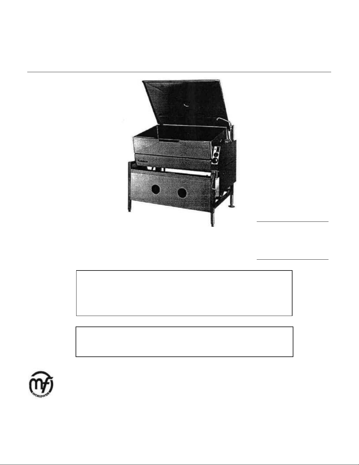
UniVerse Tilting Skillet™
Leg Electric UniVerse Skillet
MODELS: 30-STEL, 30-STEL-LX, 40-STEL, 40-STEL-LX, Open30-STEM, 30-STEM -LX, 40-STEM, 40-STEM-LX, Modular Electric UniVerse Skillet
The following general safety notices suppleme nt the specific
warnings and cautions contained in this technical manual.
They are recommended precautions that must be
understood and adhered to during the installation,
operation, and maintenance of these electrically operated
appliances.
WARNING
Do not get water on wiring in controls. Be sure to wash inside of skillet pan, inside of cover including under drip-lip,
and pouring spout area.
CAUTION
Do not install in such a manner that the service person
cannot remove the control box cover.
Supply wires must be suitable for temperature of at least
90°C. Additionally, all wiring must conform to the requirements of local and national electric codes. Conduit and fit tings should be watertight type.
Unit is equipped with an interlock switch that shuts off gas
the burners when skillet pan is more than 10° above
normal horizontal cooking position.
Page 6
UniVerse Tilting Skillet™
Skillet
Models:
Models:
MODELS: 30-STEL, 30-STEL-LX, 40-STEL, 40-STEL-LX, Open-Leg Electric UniVerse
UNIVERSE TILTING SKILLET™
30-STEM, 30-STEM -LX, 40-STEM. 40-STEM-LX, Modular Electric UniVerse Skillet
ing allows for safe use of caster mounting. Our new power tilt
operates smoothly, with manual override that works easily
when needed, without the use of electric drills required by
other manufacturers. Construction: The UniVerse Skillet has
a textured stainless steel cooking surface with reinforcement.
Heating elements turn off automatically when the cooking pan
is raised to a tilted position. The skillet is provided with a
heavy-duty gas shock assisted cover with condensate vent.
The cooking pan and cover are mounted to a 1'/2" (38 mm)
square stainless steel tube frame, permitting access to floor
for easy cleaning. The closed-base model incorporates easily
removable stainless steel panels on the front and left sides.
30-STEM
40-STEM
The cooking pan tilts to a full 93°. This is accomplished by a
gear mechanism operated manually with a collapsible hand
crank. Power tilting is also available. Both tilting methods
allow complete emptying of contents under positive control.
30-STEL
4O-STEL
UL.CUL, and NSF listed
Manufacturer reserves the right to modify materials and specifications
without notice.
DESCRIPTION
The Market Forge Electric UniVerse Tilting Skillets™ are
available in 30-gallon (87-liter) and 40-gallon (114-liter) pan
bodies with 12 kw and 18 kw inputs, respectively. Both
models are available in open-leg and closed-base frame
assemblies with manual or power tilt capabilities.
Benefits: Our UniVerse Skillets, unlike those of other braising
pan manufacturers that use clad plates, incorporate a uni-pan
design. This design reduces the potential for leaks and
eliminates the possi bility of pitting and surface rusting. The
new center-of-gravity tilt
1-1
TECHNICAL SPECIFICATIONS
Cooking Pan: The unitized cooking pan has no bottom welds
and is reinforced to resist cracking as expansion and
contraction occur. The textured cooking surface is machineapplied for a long-wearing, good appearance. The cooking
pan incorporates an easy-pour lip and 5-gallon increment
markings. Electric tubular heating elements are applied
directly to the underside of the cooking pan for better heat
transfer. An interlock switch is provided to cut power to the
heating elements when the pan is tilted more than 10° from
the normal horizontal cooking position. The counterbalanced
cover is pivoted from the frame using gas shocks to assist
lifting and ease of use. A lift handle is provided along the front
edge of the cover. A manually opened condensate vent is
positioned in the center of the cover.
Controls: The UniVerse Tilting Skillet™ comes standard with
a solid-state temperature controller with a positive OFF
position and 100°-450° Fahrenheit scale, a pilot light to
indicate when the electric heaters are ON, and a 1-hour
mechanical timer. Optional power tilting mechanism also
utilizes an UP/DOWN rocker switch. Manual tilting mechanism
uses a collapsible hand crank located below the control
panel. A high-limit temperature control is also provided The
control housing shall be water-resistant/splash-proof
Operation: The UniVerse Tilting Skillet™ Models 40-STEM
am 40-STEL will be rated at 18 kw. Models 30-STEM and 30STEM will be rated at 12 kw. All models are available in
208V, 240V 1 and 3-phase, or 480V 3-phase.
Page 7
Volts AC
1-
phase
3-
phase
1-
phase
3-
phase
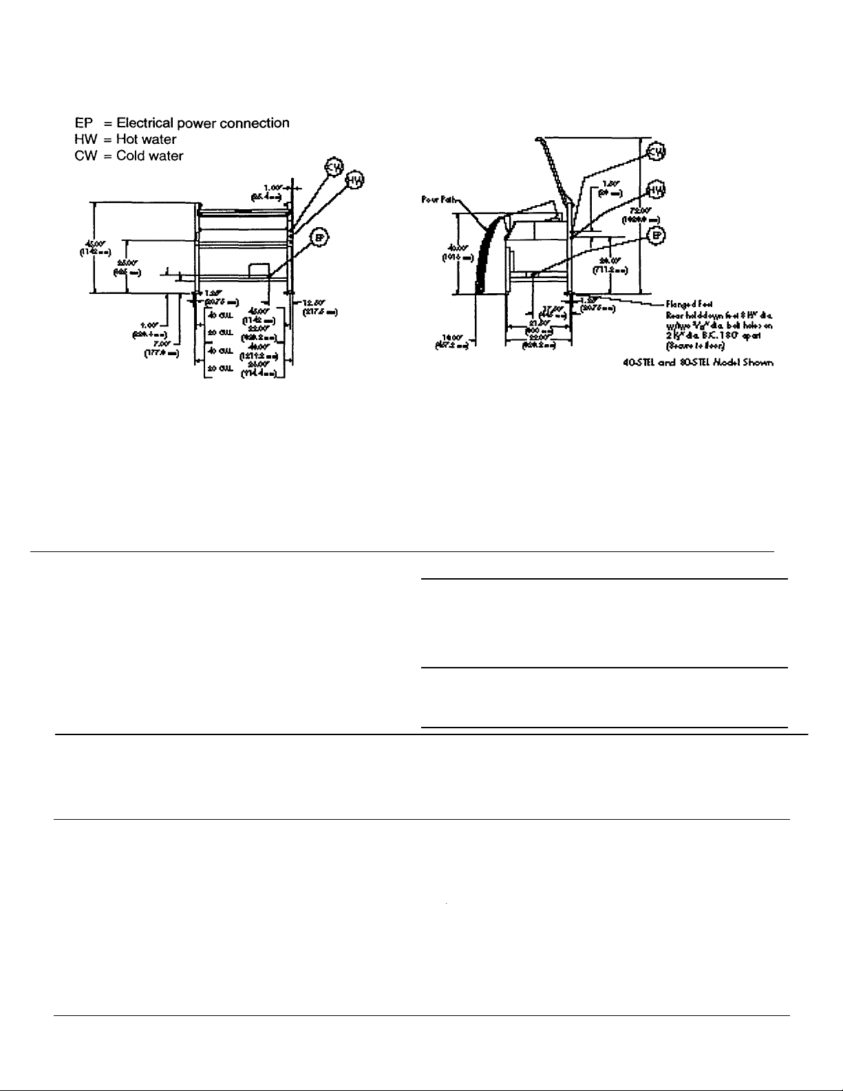
PT to cold water faucet 3/8"
UNIVERSE TILTING SKI LLET™
Market Forge Models:
UNIVERSE SKILLET
Front View
Side View
Optional at No Cost:
mm) pan holder inserts (pan not
•
Caster kit
• 480
volt
DIMENSIONS AND CAPACITY
Skillet Pan Internal Dimensions:
• Models 40-STEM and 40-STEL: 42.25" (1073 mm) wide X
9" (228 mm) deep X 25.75" (654 mm) front to back.
• Models 30-STEM and 30-STEL: 30.54" (776 mm) wide X
9" (228 mm) deep X 25.75" (654 mm) front to back.
ELECTRICAL CHARACTERISTICS
Power Supply: See chart to right for total ampdraw. Use wire
suitable for 90°C. A stepdown transformer provides power to
the 120V control circuit.
Details of other electrical systems are available upon request.
40-STEM, 40-STEL, 30-STEM, 30STEL
Skillet Pan Capacity:
• Models 40-STEM and 40-STEL: 40 gallons (152
liters)
• Models 30-STEM and 30-STEL: 30 gallons (114
liters)
40-STEL (18kw) 30-STEL (12 kw)
40-STEM (18 kw) 30-STEM (12 kw)
Water Connections
Cold Water:
Hot Water:
OPTIONS
• Power tilt mechanism
3/8" N
NPT to hot water faucet
• 208 87 50 58 33
• 240 75 43 50 29
• 480, 3-ph only — 22 — 14.5
Water Pressure Requirements: 50 psi (3.5 kg/cm2) max.; 25
psi (1.8 kg/cm2) min.
Water connections are optional when required.
Optional at Extra Cost:
• Pan support
• Removable liquid strainer
• 12" X 20" (305 mm X 508
cluded)
•Tangent draw-off valve • Strain releif kit
• Single spray hose • Single pantry faucet
• Double spray hose • Double-deck'faucet
1-2
Page 8

UniVerse Tilting Skillet™
Amps per line wire
Hz
Hz
18 kW
MODELS: 30-STEL, 30-STEL-LX, 40-STEL, 40-STEL-LX, Open-Leg Electric UniVerse Skillet
30-STEM, 30-STEM-LX, 40-STEM, 40-STEM-LX, Modular Electric UniVerse Skillet
1. Remove carton from skid, being careful not to
dent or scratch finished surfaces of unit.
2. Inspect unit carefully for shipping damage. File
claim with carrier immediately if damage is found.
3. Remove screws holding unit to skid.
4. Transfer unit to desired position. Make unit level
and steady by adjusting feet to compensate for
floor irregularities. Secure rear feet to floor by
using 5!^" screws.
NOTE : Do not install in such a manner that service
person cannot remove control box cover.
5. Drop down hinged front cover of connection box.
Loosen screws and clips on top of box.
6. Connect unit to a branch circuit having a voltage
and circuit type specified on name plate and of
sufficient size to carry load. The amps per line
per line wire for the various voltage ratings are
shown in Ta ble 2.1 below.
TABLE 2.1 AMPS PER LINE PER LINE WIRE
MODELS: 30-STEL, 30-STEL-LX, 30-STEM, 30-STEM-LX MODELS: 40-STEL, 40-STEL-LX, 40-STEM, 40-STEM-LX
3-Phase, 4 wire, 50 Hz
10.1 kW 220/380V 15
12 kW 240/415V 16.7
(EXPORT ONLY)
12 kW, Single Phase Unit, 60
Amps per line
L#1 L#2
208V
240V
52 52
50 50
12 kW, 3-Phase Unit, 60
Amps per line
L#1 L#2 L#3
208V 33 33 33
240V 29 29 29
480V 14.5 14.5 14.5
NOTE : Supply wires must be suitable for temperature
of at least 90°C. Additionally, all wiring must
conform to the requirements of local and
national electric codes. Conduit and fittings
should be watertight type.
7. Connect ground wire from electrical service to
ground lug.
8. Reinstall hinged front cover of connection box
securely.
9. Ensure that skillet is firmly seated on frame before
checking connection and functioning of controls.
NOTE : Unit is equipped with an interlock switch that
shuts off current to heating elements when
skillet pan is more than 10° above normal
horizontal cooking position.
10. Switch on current supply to unit. Check for proper
functioning of controls and heating elements (see
Section 3— Operating Instructions).
3-Phase, 4 wire, 50 Hz
Amps per line wire
15.1 kW 23
240/415V 25
18 kW, Single Phase Unit, 60 Hz
Amps per line
L#1 L#2
208V
240V
87 87
75 75
18 kW, 3-Phase Unit, 60 Hz
Amps per line
L#1 L#2 L#3
208V 50 50 50
240V 43 43 43
480V 22 22 22
2-1
Page 9
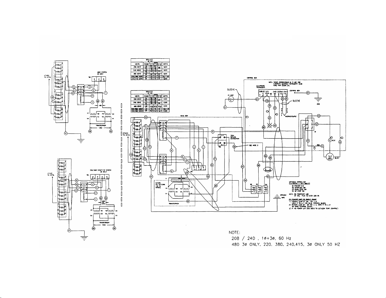
FIG. 2.1
OPTIONAL WIRING FOR ELECTRICAL LIFT SKILLET
2-2
Page 10
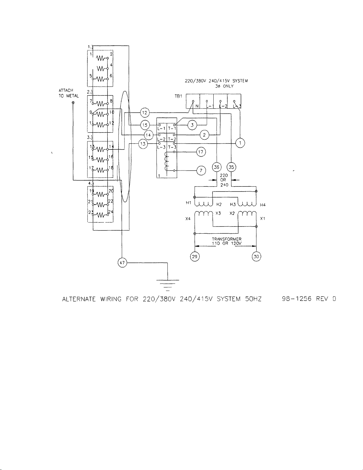
FIG. 2.2
ALTERNATE WIRING FOR 220/380V 240/415V SYSTEM
2-3
Page 11
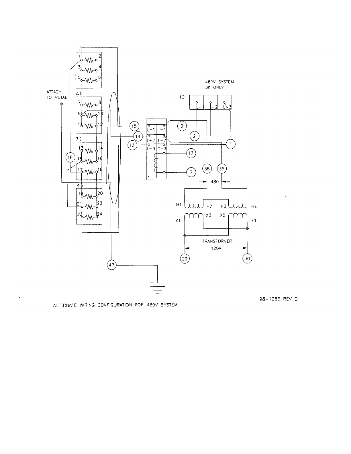
FIG. 2.3
ALTERNATE WIRING CONFIGURATION FOR 480V SYSTEM
2-4
Page 12

UniVerse Tilting Skillet™
MODELS: 30-STEL, 30-STEL-LX, 40-STEL, 40-STEL-LX, Open-Leg Electric UniVerse Skillet
30-STEM, 30-STEM-LX, 40-STEM, 40-STEM-LX, Modular Electric UniVerse Skillet
INTRODUCTION
This technical manual contains general information, installation, operation, principles of operation, troubleshooting
guide, and maintenance information for the electrically
operated UniVerse Tilting Skillet. Also included is an
illustrated parts list and a directory of authorized parts and
service agencies.
Description
The Market Forge Industries UniVerse Models 30-STEL (12
kW input) and 40-STEL (18 kW input) are electrically
operated skillets, tilting type, with 30- and 40-gallon capacities, respectively. They are equipped with a solid-state
thermostat and high-limit control with a 100°F -to-450°F
temperature scale.
Basic Functions
The UniVerse Tilting Skillet is a very versatile cooking appliance. It can perform basic cooking functions, such as
brais ing meat, sauteing, pan-frying chicken, steaming
vegetables, boiling, and simmering. Refer to Section 4—
Test Kitchen Bulletin, which gives detailed information on
the various types of food products that can be cooked in
the skillet.
COOKING
1. Ensure that electric power connection has been made
correctly and that branch circuit breaker at building supply
box is ON.
2. Ensure that skillet is in full down position and clean before using.
NOTE: Electric power automatically shuts off when skillet
is tilted more than 10° above normal horizontal cooking
position.
3. Set thermostat at desired temperature by turning ther
mostat control knob clockwise. See Section 4—Test
Kitchen Bulletin for thermostat settings.
4. Preheat to desired temperature (with cover down)
before grilling, pan-frying, or any other method of cooking
except boiling.
NOTE: For best results, allow unit to cycle ON/OFF once.
5. Ensure that cover is up for most types of cooking
except for simmering, braising, or boiling. Cover has drip lip at rear to direct condensate into skillet.
6. Remove cooked food immediately to prevent overcooking. Tilt skillet by turning handcrank clockwise or
pushing tilt switch.
7. Lower skillet by turning handcrank counterclockwise on
pushing tilt switch.
SHUT-DOWN
Turn thermostat control knob counterclockwise to OFF
when no further heating is desired.
CLEANING
Unit must be cleaned after each use. Proceed as follows:
1. When all food has been removed from skillet, add water
to loosen/dissolve any remaining food.
2. Wash skillet using mild detergent, water and nylon
brush. If food is stuck to skillet surface, soak and use a
little heat to loosen food.
WARNING: Do not get water on wiring or in controls. Be
sure to wash inside of skillet pan, inside of cover including
under drip-lip. and pouring spout area.
3. Rinse and dry entire unit.
3-1
Page 13

UniVerse Tilting Skillet™
Skillet
MODELS: 30-STEL, 30-STEL-LX, 40-STEL, 40-STEL-LX, Open-Leg Electric UniVerse
30-STEM, 30-STEM -LX, 40-STEM, 40-STEM-LX, Modular Electric UniVerse Skillet
COOKING FACTS ON PARADE
1. The UniVerse Skillet is one of the most versatile pieces of
equipment to be found in any restaurant or institutional
kitchen.
2. This unit will stew, simmer, pan-fry, braise, grill, and
saute —and all with a very uniform heat pattern.
NOTE: Do not attempt to deep fry with your skillet!
3. For best results, the Tilting Skillet should always be preheated and allowed to cycle once.
4. A great deal of heavy lifting and transferring of foods from
one pan to another can be eliminated, and, therefore, pot
washing will be reduced.
5. This type of equipment usually reduces the total cooking
time by as much as 25% on combination dishes.
6. Sauces usually lose less moisture, as the cover reduces
evaporation.
7. Large batches of gourmet items can be prepared with less
work and with more uniform results.
8. Frozen vegetables can be cooked in the UniVerse Skillet
in the serving pan, then removed and transferred directly
to the serving line.
9. The following temperatures should be used:
Simmering: maximum of 200°F
Sauteing: 225-275°F
Searing: 300-350°F
Frying: 325-375°F
Grilling: 350-425°F
10. Temperatures of approximately 200°F should always be
used for milk-based products, or scorching will take place.
Lower temperatures (150-175°F) prevent thickening.
4-1
11. Some items should be started at a high temperature
and then reduced. This permits sealing for about 20%
of the time and cooking for the remaining 80%.
12. The cover has a lip at the back edge that directs the
con-densate on the cover back into the skillet.
13. The unit tilts easily to 90°, and receiving pan is
always approximately 2 inches from the pouring Up of
the skillet.
14. The stainless steel UniVerse Skillet is rapidly cleaned
with a mild detergent. Water, waste, and scraps are
eas ily removed into the receiving pan for disposal. (It
is always recommended that this type of unit be
presoaked if possible.)
15. Breakfast foods such as sausage, bacon, pancakes,
fried eggs, scrambled eggs, and French toast are a
few of the more common items that can be cooked in
the UniVerse Skillet.
16. When cooking meat or poultry, all pieces should be of
fairly uniform size and weight and should be turned at
least once while simmering.
17. This unit can be converted to a proof box by placing a
small amount of water in the pan to form steam and
then placing the food in another pan. The thermostat
should be set very low (100-150°F).
18. The unit can also be used as a holding cabinet by
adding water and setting the thermostat at
approximately 175°F.
19. When using water over and over for vegetable
cookery, be sure to add water occasionally to keep
level at about 3-4 inches. Thermostat should be set at
250°F.
20. Perforated 2 1/2 "-deep pans are suggested for
vegetables for the most satisfactory results. The pan,
can then be removed easily and transferred to the
serving line.
Page 14
UNIVERSE SKILLET
Boiled
—
Hard
TABLE 4.1
COOKING PORTIONS AND TIMES
THE UNIVERSE SKILLET
All Modular & Tubular Leg Models
The UniVerse Skillet is one of the most versatile pieces of equipment to be found in any restaurant or institutional kitchen.
It enables the cook to stew, simmer, pan-fry, braise, grill, or saute, and all with a very uniform heat pattern. The figures given
below are suggested quantities and temperature settings and estimated numbers of orders per load and per hour. When two
temperatures are given, the first is to start the product, the second to finish the product.
ITEM
BREAKFAST FOODS
Bacon
Eggs
Boiled—Soft 1 egg 225° 8 50 50 75 75
PORTION
SIZE
3 slices
1 egg 225° 5 50 50 75 75
THERMOSTAT
SETTING
350°
BATCHES
PER
HOUR
12
30 GAL.
PER LOAD
QTY YIELD
20 10
40 GAL.
PER LOAD
QTY YIELD
30 15
Fried 1 egg 400° 4 30 30 45 45
Poached 1 egg 225° 5 36 36 60 60
Scrambled 1 1/2 eggs 300° 200°
French Toast 3 slices 450° 7 35 slices 12 50 slices 17
Regular Oatmeal 1/2 cup 250° 2 200 500 400 1000
Pancakes 2 each 400° 10 30 ea. 15 50 ea. 25
1 18 gal 720 28 gal. 1100
FISH
Clams 1 pt. 400° 10 10 qts. 20 15 qts. 30
Fish Cakes 2-3 oz. 400° 5 70—3 oz. 35 110—3 oz. 55
Haddock Filet 4 oz. 400° 4 60—4oz. 60 90—4 oz. 90
Halibut Steak 5oz. 450° 3 60—4oz. 60 90—4 oz. 90
Lobster 1—1# 350° 4 20—1# 20 30—1# 30
Swordfish 5 oz. 450° 3 50—5 oz. 50 75—5 oz. 75
SAUCES, GRAVIES, SOUPS
Brown Gravy 1 oz. 350° 200°
Cream Sauces 2oz. 250° 175°
Cream Soup 6oz. 200° 1 18 gals. 375 35 gals. 725
French Onion Soup 6 oz. 225° 1 18 gals. 350 35 gals. 700
Meat Sauce 4 oz. 350° 200°
4-2
2 18 gals. 2300 35 gals. 4500
1 18 gals. 1150 3,5 gals. 2250
1 18 gals. 575 35 gals. 1100
Page 15
TABLE 4.1 COOKING PORTIONS AND TIMES—
40 GAL.
cont'd.
ITEM
MEAT, POULTRY
Bacon 3 slices 350° 12 2# 10 3# 15
Beef
American Chop Suey 6 oz. 400° 225° 2 18 gals. 350 35 gals. 700
Beef Stew 8oz. 300° — 18 gals. 280 35 gals. 560
Corned Beef Hash 5oz. 400° 5 16# 50 25# 75
Cheeseburger 3oz. 300° 12 7# 35 10# 50
Hamburger 3oz. 300° 15 7# 35 10# 50
Meatballs 1 oz. 400° 225° 3 12 1/2# 65 18# 100
Pot Roast 2oz. 350° 200° — 120# 500 180# 750
Salisbury Steak 5oz. 400° 3 16# 50 24# 75
Sirloin Steak 6 oz. 400° 5 15# 40 22 1/2# 60
Swiss Steak 4 oz. 300° 200° 1 25# 100 40# 160
Chicken
PORTION
SIZE
THERMOSTAT
SETTING
BATCHES
PER
HOUR
\
30 GAL.
PER LOAD
QTY YIELD
PER LOAD
QTY YIELD
Pan-Fried
Whole 2oz. 350° 200° — 16—5# 200 24—5# 265
Frankfurters
Grilled 2oz. 300° 8 22# 176 33# 264
Boiled 2oz. 250° 12 16# 128 25# 200
Ham Steak 3 oz. 400° 8 10# 50 15# 75
Pork Chops 5 oz. 350° 4 15# 50 25# 75
Sausage Links 3 links 350° 7 30# 120 45# 180
Turkey
Off Carcass 2oz. 400° 200° — 3—26-30# 200 4—26-30# 275
On Carcass 2oz. 400° 200° — 4—16-20# 175 6—16-20# 265
Grilled Cheese Sandwiches 1 sand. 400° 8 35 sand. 35 50 sand. 50
Macaroni & Cheese 8oz. 200° 2 18 gals. 300 35 gals. 525
Rice 4 oz. 350° 225° 1 20# raw 320 40# 650
Spaghetti 4 oz. 350° 225° 2 8# raw 200 12# 300
2—1/4's
350° 3 50 pieces 25 80 pieces 40
MISCELLANEOUS
Page 16

TABLE 4.1 COOKING PORTIONS AND TIMES—
cont'd.
ITEM
Portion
Size
Thermostat
Setting
Batches
per
Hour
30 Gal.
per Load
Qty. Yield
40 Gal.
per Load
Qty. Yield
VEGETABLES
Canned 3oz. 400° 6 30# 125 45# 200
Fresh
Beans—Wax, Green
Beets
Broccoli
Cabbage
Carrots
Cauliflower
Corn
Potatoes
Spinach
Turnips
Frozen
Beans—French, Green
Lima Beans
Broccoli
3 oz.
3oz. 400° 1 30# 125 60# 300
3oz. 400° 3 25# 125 40# 200
3oz. 400° 5 20# 80 30# 125
3oz. 400° 2 35# 150 70# 300
3 oz. 250° 5 15# 75 25# 125
1 ear 400° 8 50 ears 50 75 ears 75
3oz. 400° 2 40# 200 60# 300
4 oz. 250° 10 6# 25 9# 35
4oz. 400° 2 20# 100 30# 150
3 oz.
3 oz. 250° 4 15# 60 22 1/2# 90
3oz. 400° 8 12# 50 18# 75
400°
400°
3
6
25#
15#
125
60
50#
22 1/2#
250
90
Sliced Carrots
Small Whole Carrots
Corn
Small Whole Onions
Peas
Spinach
3oz. 250° 6 15# 60 22 1/2# 90
3oz. 250° 3 15# 50 22 1/2# 90
3oz. 250° 18 15# 50 22 1/2# 90
3oz. 250° 7 15# 50 22 1/2# 90
3 oz. 400° 10 15# 75 22 1/2# 110
3oz. 400° 3 15# 75 22 1/2# 110
DESSERTS, PUDDINGS, SWEET SAUCES
Butterscotch Sauce 1 oz. 200° 1 18 gals. 2300 35 gals. 4500
Cherry Cobbler 3oz. 200° 1 18 gals. 750 35 gals. 1500
Chocolate Sauce loz. 200° 1 18 gals. 2300 35 gals. 4500
Comstarch Pudding 4 oz. 200° 1 18 gals. 575 35 gals. 1100
Fruit Gelatin 3oz. 250° 2 18 gals. 750 35 gals. 1500
4-4
Page 17

Skillet
1 98-1296
98-
1295
FRAME WELD ASSY.
1 1 2 98-
1010
98-
1010
GEARBOX
1 1 3 98-
1051
98-
1051
ASSY, BEARING SUPPORT
1 1 4 98-
1559
98-
1559
BEARING MOUNT LEFT
1 1 5 98-
1500
98-
1500
BEARING MOUNT RIGHT
1 1 6 98-
1357
98-
1556
SKILLET
PAN ASSY
1 1 7 98-
1505
98-
1024
SHAFT
1 1 8 08-
7809
08-
7809
SHOULDER SCREW
2 2 9 98-
1511
98-
1093
STIFFENER, PAN COVER
1 1 10 98-1510 98-1090
COVER
1 1 11 98-
1012
98-
1012
HINGE
2 2 12 91-
9325
91-
9525
KNOB
4 4 13 91-
9262
91-
9262
ARM, VENT COVER
1 1 14 91-
9261
91-
9261
VENT COVER
1 1 15 98-
1454
98-
1454
ELECTRIC
NEMA BOX ASSY,
208 &
240V MANUAL TILT UNITS
1 1
15A 98-1451
98-
1451
ELECTRIC
NEMA BOX ASSY,
208 &
240V POWER. TILT UNITS
1 1
15B 98-1540
98-
1540
ELECTRIC NEMA BOX
ASSY,
240/380V
&.
220/415V MANUAL TILT
1 1 15C 98-1541
98-
1541
ELECTRIC NEMA BOX ASSY,
240/380V
& 220/415V
POWER TILT
1 1 15D 98-
1455
98-
1455
ELEC
TRIC NEMA BOX ASSY, 480V MANUAL TILT UNlTS
1 1
15E 98-1452
98-
1452
ELECTRIC NEMA BOX ASSY, 480V POWER TILT UNITS
1 1 17 98-
1068
98-
1068
WELD ASSY, CAM LIFT, POWER LIFT UNITS
1 1 18 98-
1028
98-
1028
SHAFT JOINT
1 1 19 98-
1258
98-
1258
ARM, EXTENSION
2 2 20 98-
1212
98-
1212
ARM, LIFT
2 2 21 08-
7810
08-
7810
INSERT
5/16
2 2 22
REF REF SHOCK. MOUNT, COMES WITH SHOCKS, NO N
UMBER
4 4 23 08-
7806
08-
7806
GAS SHOCKS
2 2 24 98-
1402
98-
1402
MOTOR MOUNTING BRACKET, POWER LIFT UNITS
1 1 25 98-
0985
98-
0985
MOTOR.
POWER LIFT UNITS
1 1 26 98-
1288
98-
1288
CONTROL BOX
1 1 27 10-
5520
10-
5520
60 MIN. TIMER
1 1 28 09-
5267
09-
5267
TIMER KNOB
1 1 29 08-
7915
08-
7915
THERMOSTAT
1 1 30
REF REF THERMOSTAT KNOB, COMES WITH THERMOSTAT, NO NUMBER
1 1 31 10-
5052
10-
5052
LIGHT 1 1 32 08-6520
08-
6520
POWER SWITCH, POWER LIFT UNITS
1 1
32A 98-1508
98-
1508
POWER SWITCH HOLE PLUG, MANUAL TILT UNITS
1 1 33 91-
9144
91-
9144
LEFT SPRING
1 1 34 91-
9145
91-
9145
RIGHT SPRING
1 1 35 08-
7815
08-
7813
INSERT
5/8 2 2 36 98-1216 98-
1216
UNIVERSAL, EXTENDED, POWER LIFT UNITS
1 1 37 98-
1526
98-
1526
WELD ASSY, CAM, UP AND DOWN
2 2 38 98-
1270
98-
1270
HANDLE BRACKET, MANUAL TILT UNITS
1 1 39 98-
1555
98-
1555
CRANK HANDLE
,
MANUAL TILT UNITS
1 1
39A 98-1262
98-
1262
CRANK
HANDLE, P
OWER TILT UNITS
1 1 40 98-
1538
98-
1559
WELT ASSY,TlLTlNG MECHANISM
1 1
MODELS:
ITEM
PART
UniVerse Tilting Skillet™
30-STEL, 30-STEL-LX, 40-STEL, 40-STEL-LX, Open-Leg Electric UniVerse
30-STEM, 30-STEM-LX, 40-STEM, 40-STEM-LX, Modular Electric UniVerse Skillet
TABLE 5.1
UNIVERSE SKILLET, TOP ASSEMBLY
Parts List
NO.
PART
NO.
DESCRIPTION
30 GAL
QTY.
40 GAL
QTY.
5-1
Page 18

FIG. 5.1 UNIVERSE SKILLET, TOP
ASSEMBLY
5-3
Page 19

FIGURE 5.2
UNIVERSE SKILLET, PAN ASSEMBLY
Page 20

TABLE 5.2
1 1
1
1
1
1
5-4 S-2468
Rev.
A
3/98
UNIVERSE SKILLET, PAN ASSEMBLY
Parts List
ITEM
30 GAL. PART
NO.
40 GAL.PART
NO.
DESCRIPTION
30 GAL.
QTY.
1 98-1245 98-1224 PAN WELD ASSY. 1 1
2 98-1081 98-1080 HEATING ELEMENTS, 208 V 4 4
2A 98-1685 98-1082 HEATING ELEMENTS, 240 V 4 4
3 98-1347 98-1547 U-CHANNEL 5 9
4 98-1254 98-1254 COVER, MIDDLE HEATING ELEMENT 1 1
5 98-1221 98-1255 COVER, SIDE HEATING ELEMENT 2 2
6 91-7520 91-7520 HI LIMIT THERMOSTAT BRACKET
7 08-6551 08-6551 HI LIMIT THERMOSTAT
8 98-1255 98-1255 BRACKET, HEATING ELEMENT CONDUIT
9 08-5894 08-5894 MARKET FORGE NAME PLATE
10 08-6305 08-6305 TEMPERATURE SENSOR
40 GAL.QTY.
1
1
1
1
Page 21

TABLE 5.3
UNIVERSE SKILLET, NEMA BOX ASSEMBLY
Parts List
ITEM PART NO. DESCRIPTION QTY.
1 98-1336 NEMA BOX, LARGE 1
2 08-7901 MICROSWITCH, POWER TILT UNITS 3
2A 08-7901 MICROSWITCH, MANUAL TILT UNITS 1
3 91-9178 CAPACITOR BRACKET 1
4 10-5503 TERMINAL BLOCK BLACK 1
5 10-5070 END PIECE, TERMINAL BLOCK, BLACK 1
6 10-5220 ELECTRICAL GROUND 1
7 10-5944 CONTACTOR 1*
8 98-1265 MOUNTING PLATE, NEMA BOX 1
9 10-6262 TERMINAL BLOCK, WHITE 1
10 10-6963 END PIECE, TERMINAL BLOCK, WHITE 1
11 10-5234 TRANSFORMER, 250 VA 1
12 REF CAPACITOR, COMES WITH MOTOR 1
14 08-7826 MICROSWITCH HOLE PLUG, MANUAL TILT UNITS 2
15 08-7846 BOOT, RUBBER, MICROSWITCH 1
15A 08-7846 BOOT, RUBBER, MICROSWITCH 2*
*0nly 208 V and 240V units have 2 contactors; all others have 1.
5-6
Page 22

FIG. 5.3
UNIVERSE SKILLET, NEMA BOX ASSEMBLY
Page 23

Universe Tilting Skillet™
que bottom of skillet
MODELS: 30-STEL, 30-STEL-LX, 40-STEL, 40-STEL-LX, Open-Leg Electric UniVerse Skillet
30-STEM, 30-STEM-LX, 40-STEM, 40-STEM-LX, Modular Electric UniVerse Skillet
PROBLEM
1. Uneven heating. a. Defective element.
2. Signal Light Out a. Burnt out bulb.
3. Unit Fails To Heat a. Circuit breaker is off.
PROBABLE CAUSE
b. Uneven torquing of element
clamp plate nuts.
c. Temperature control out of
calibration or defective.
d. Uneven distribution of
ceramic adhesive.
b. Broken temperature control.
c. Loose electrical connection.
b. Malfunction of interlock
switch.
c. Contactor does not pull in.
d. Ceramic adhesive is not
conducting heat.
TROUBLESHOOTING GUIDE
TABLE 6.1
REMEDY
a. Replace element.
b. Retor
( 5 foot pounds only).
c. Calibrate or replace.
d. Contact Service Department.
a. Replace.
b. Replace.
c. Repair.
a. Reset circuit breaker.
b. Adjust or replace.
c. Replace contactor. Check
temperature control.
d. Check temperature of bottom
plate and interior pan surface
(Fig. 3-6, No. 11). If different,
contact Service Department.
PART NO
1. Ensure that pan is empty and clean before calibrating.
2. Place a surface thermometer on approximate center of
griddle surface.
NOTE: Check that magnets on thermometer extend
through holes in circular base plate and are in
complete contact with griddle surface.
CALIBRATION OF TEMPERATURE CONTROL
3. Set temperature control knob at 375°F (191°C).
4. Allow skillet to preheat and stabilize 2—3 cycles.
5. Record thermometer reading. If a temperature of 370°380°F (188°-193°C) is recorded, procedure is complete
If not, go on to step 6.
6-1
Page 24

6. Remove control box cover by removing screw in rear and
right side of cover.
7. Locate temperature control circuit board (see Figure 6.1)
and calibrate as follows:
a. If temperature goes above 375 °F (191 °C), turn setpot
labeled HI counterclockwise to decrease temperature.
b. If temperature goes below 375°F (191°C), turn setpot
labeled HI clockwise to increase temperature.
NOTE: Turn the HI setpot only. Be careful when turning
setpot—just a slight turn (approximately 22°) will
change temperature by 25°F.
8. Allow skillet to cycle three (3) times. This cycling allows
temperature control to stabilize.
UNIVERSE SKILLET
10. Replace control box cover by pushing down and replacing screw in rear and right side of cover.
9. Record thermometer reading when pilot light goes out. If a
temperature of 370°-380°F (188°-l93°C) is recorded,
calibration procedure is complete. If not, repeat steps 7
and 8 until appropriate temperature is recorded.
REPLACEMENT OF TEMPERATURE CONTROL
1. Place circuit breaker in OFF position.
2. Remove skirted dial knob by pulling it off the control box
cover.
3. Remove control box cover by removing screw in rear and
right side of cover.
4. Disconnect all wire leads from temperature control
ADJUSTMENT OF INTERLOCK SWITCH
1. Tilt skillet pan all the way in the downright position.
NOTE: If adjusting the interlock switches for the tilt
mechanism in a power tilt unit, the pan will have to
be all the way in the upright position to adjust one
of the switches.
2. Place circuit breaker in OFF position.
FIG. 6.1 TEMPERATURE CONTROL CIRCUIT BOARD
NOTE: Leads should be marked appropriately to facilitate
re-installation.
5. Remove temperature control by removing two (2) pan
head nuts from side of control box.
6. Install new temperature control and reverse steps 1-5.
4. Loosen the bottom nut of the switch until it contacts with
the cam and depresses the plunger on the switch.
5. Tighten the top nut on the switch to keep the switch in the
desired location.
6. Close and fasten the nema box by tightening the 2 screws
at the top of the box.
3. Open the nema box by loosening the two screws at the
top of the nema box.
7. Place circuit breaker in ON position.
6-2
Page 25

UNIVERSE SKILLET
REPLACEMENT OF ELECTRIC ELEMENTS
1. Tilt skillet pan upright by turning handwheel clockwise.
2. Remove bottom cover, and both heat shields. When bottom cover is removed, terminals are exposed. Remove
wiring.
3. Remove bottom clamp plates to expose elements by removing nuts and lockwashers on studs.
4. Remove spacers between elements and mark their location.
5. Replace the defective element and reverse the procedure.
IMPORTANT: In replacing the elements, clamp plates
are torqued to 4 1/2 foot pounds (20 New-tons).
Use a torque wrench of 0-5 Ibs. (0-66 Newtons) or
less.
CLEANING AND PREVENTIVE MAINTENANCE
1. The skillet should be cleaned daily.
2. Wash th e skillet with a mild detergent and hot water. If
food is stuck to the surface of the skillet pan, soak it and
use a little heat to loosen the food. Then, wash with clear
water and dry.
TABLE 6.2 HEATER
ELEMENTS—ELECTRIC
3. Be sure to wash under the skillet cover and rinse with
clear water.
4. Check the skillet pouring lip comers to be sure they are
clean. Also, wash around the exterior of the skillet.
Rinse with clear water and air dry.
Page 26

UniVerse Tilting Skillet™
Skillet
MODELS: 30-STEL, 30-STEL-LX, 40-STEL, 40-STEL-LX, Open-Leg Electric UniVerse
30-STEM, 30-STEM -LX, 40-STEM, 40-STEM-LX, Modular Electric UniVerse Skillet
TABLE 7.1
UNIVERSE SKILLET OPTIONS, SINGLE PANTRY FAUCET
Parts List
ITEM PART NO. DESCRIPTION QTY.
1 98-1199 CONTROL BOX REAR, PANTRY FAUCET 1
2 98-1360 MOUNTING PLATE, SINGLE PANTRY FAUCET 1
3 98-1366 SINGLE PANTRY FAUCET 1
4 98-1368 ADAPTER, SINGLE PANTRY FAUCET 2
5 10-5753 SPRAY NOZZLE WITH SWIVEL NOZZLE 1
6 10-3767 NIPPLE, FILL FAUCET RISER, 6" 1
7 REF #8-32 WELDNUT 8
8 98-1475 TUBING, BRAIDED TEFLON 1
9 98-1477 COUPLER, BRASS HOSE BARB, 3/8 ID TO 3/8 PIPE 1
10 98-0877 ASSY, WATER LINE INLET 1
11 10-1761 #8-32 SCREW, 3/8 LG, S.S 1
12 08-1206 HOSE CLAMP 2
13 98-1479 COUPLER, BRASS HOSE BARB, 3/8 I.D X 1/2" THD FEMALE 1
Page 27

FIG. 7.1
UNIVERSE SKILLET OPTIONS, SINGLE PANTRY FAUCET
7-2
Page 28

TABLE 7.2
UNIVERSE SKILLET OPTIONS, DOUBLE PANTRY FAUCET
Parts List
ITEM PART NO. DESCRIPTION QTY.
1 98-1199 CONTROL BOX REAR, PANTRY FAUCET 1
2 98-1362 MOUNTING PLATE, DOUBLE PANTRY FAUCET 1
3 98-1367 DOUBLE PANTRY FAUCET 1
4 REF #8-32 WELDNUT, S.S 8
5 98-1475 TUBING, BRAIDED TEFLON, 3/8 ID X 5/8 OD X 10.5 LONG 1
6 98-1474 TUBING, BRAIDED TEFLON, 3/8 ID X 5/8 OD X 15 LONG 2
7 10-5753 SPRAY NOZZLE WITH SWIVEL BODY 1
8 10-3767 NIPPLE, FILL FAUCET RISER 6" LG 1
9 98-1477 COUPLER, BRASS HOSE BARB, 3/8 ID X MALE PIPE 3/8 5
10 98-0877 ASSY, WATER LINE INLET 1
11 10-1761 #8-32 SCREW, S.S., 3/8 LG 6
12 10-3108 REMOTE VALVE 1
13 98-1479 COUPLER, BRASS HOSE BARB, 3/8 ID TO 1/2 F. THD 1
14 08-1206 HOSE CLAMP 6
Page 29

DETAIL A
-
A
FIG. 7.2
UNIVERSE SKILLET OPTIONS, DOUBLE PANTRY FAUCET
BACK VIEW
Page 30

TABLE 7.3
UNIVERSE SKILLET OPTIONS, SINGLE SPRAY HOSE
Parts List
ITEM PART NO. DESCRIPTION QTY.
1 98-1199 CONTROL BOX REAR, PANTRY FAUCET 1
2 98-1360 MOUNTING PLATE, SINGLE PANTRY FAUCET 1
3 98-1366 SINGLE PANTRY FAUCET 1
4 98-1368 ADAPTOR, SINGLE PANTRY FAUCET 2
5 98-1477 COUPLER, BRASS HOSE BARB, 3/8 ID TO 3/8 THD MALE 1
6 98-1401 CHECK VALVE, 1/2 X 1/2 IPS 1
7 REF #8-32 WELDNUT, S.S, 6
8 98-1475 TUBING, BRAIDED TEFLON 3/8" X 5/80.D X 10.5 LG 1
9 08-4892 COUPLER, BRASS HOSE BARB, 3/8 ID X TO MALE 1/2 PIPE 2
10 98-0877 WATER LINE INLET, ASSY 1
11 10-1761 #8-32 SCREW , 3/8 LG S.S. 4
12 10-0959 SPRAY HOSE ASSY. 1
13 08-1206 HOSE CLAMP 2
Page 31

DETAIL A
-
A
BACK VIEW
Page 32

TABLE 7.4
UNIVERSE SKILLET OPTIONS, DOUBLE SPRAY HOSE
Parts List
ITEM PART NO. DESCRIPTION QTY.
1 98-1199 CONTROL BOX REAR, PANTRY FAUCET 1
2 98-1362 MOUNTING PLATE, DOUBLE PANTRY FAUCET 1
3 98-1367 DOUBLE PANTRY FAUCET 1
4 REF #8-32 WELDNUT, S.S. 8
5 98-1475 TUBING, BRAIDED TEFLON, 3/8 ID X 5/8 OD X 10.5 LONG 1
6 98-1474 TUBING, BRAIDED TEFLON, 3/8 ID X 5/8 OD X 15 LONG 2
7 08-4892 COUPLER, BRASS HOSE BARB, 3/8 ID TO 1/2 THD MALE 1
8 98-1401 CHECK VALVE 1
9 98-1477 COUPLER, BRASS HOSE BARB, 3/8 ID X MALE PIPE 3/8 5
10 98-0877 WATER LINE INLET ASSY. 1
11 10-1761 #8-32 SCREW, S.S 3/8" LG 1
12 10-3108 REMOTE VALVE 1
13 98-0959 SPRAY HOSE ASSY. 1
14 08-1206 HOSE CLAMP 6
Page 33

DETAIL A
-
A
BACK VIEW
Page 34

TABLE 7.5
UNIVERSE SKILLET OPTIONS, PAN SUPPORT
Parts List
ITEM PART NO. DESCRIPTION QTY.
1 98-1186 PAN SUPPORT WELD ASSEMBLY 1
2 08-7838 JAM NUT, 1/4-20 6
3 98-1378 PIVOT ARM 2
4 98-1188 FRAME BRACKET 1
5 10-1814 BOLT, 1/4-20 X 3/4 STAINLESS 4
6 98-1416 PIVOT STUD 4
7 08-7837 BELLVILLE SPRING WASHER, STAINLESS STEEL 4
8 98-1417 LOWER ARM 1
9 98-1419 UPPER ARM 1
10 98-1415 GUARD 1
11 10-1788 SCREW, 10-32 X 3/8 LONG 1
Page 35

FIG. 7.5
UNIVERSE SKILLET OPTIONS, PAN SUPPORT
7-10
Page 36

TABLE 7.6
UNIVERSE SKILLET OPTIONS, CASTERS WITH GAS STRAIN RELIEF
Parts List
ITEM PART NO. DESCRIPTION QTY.
1 98-1421 GAS STRAIN RELIEF KIT FOR CASTER UNITS 1
2 98-1523 CASTER WITH BRAKE 2
3 98-1191 CASTER WITHOUT BRAKE 2
4 08-7839 EYE-BOLT, 1/4-20 X 2.00" LG 1
5 S-4839 INSTALLATION INSTRUCTIONS 1
FIG. 7.6
SEE INSTALLATION INSTRUCTIONS S-4839
TABLE 7.7
UNIVERSE SKILLET OPTIONS, CASTERS WITH GAS STRAIN RELIEF
Parts List
ITEM PART NO. DESCRIPTION QTY.
1 98-1523 CASTER WITH BRAKE 2
2 98-1191 CASTER WITHOUT BRAKE 2
3 S-4839 INSTALLATION INSTRUCTIONS 1
FIG. 7.7
SEE INSTALLATION INSTRUCTIONS S-4839
TABLE 7.8
UNIVERSE SKILLET OPTIONS, CASTERS WITH GAS STRAIN RELIEF
Parts List
ITEM PART NO. DESCRIPTION QTY.
1 98-1421 GAS STRAIN RELIEF KIT FOR CASTER UNITS 1
FIG. 7.8
SEE INSTALLATION INSTRUCTIONS S-4839
7-11
Page 37

FIG. 7.6-8
UNIVERSE SKILLET OPTIONS, S-4839
INSTALLATION INSTRUCTIONS FOR
CASTERS ON THE UNIVERSE SKILLET
WARNING: Before raising skillet base make sure the pan is in the down position for steps 1-8.
1. Raise the front of the skillet base and brace with front of skillet off the ground.
2. Insert casters with brakes into the front legs of the frame
NOTE: Casters must screw fully into the frame of the skillet in order for them to be able to be
tightened.
3. Tighten the nut at the base of the casters until casters are securely fastened into the legs of the frame.
4. Put the universe skillet down on the floor.
5. Apply the brakes in the front by stepping on the lever on the side of the front casters until it is in the on
position.
6. Raise the rear of the skillet base and brace with rear of skillet off the ground.
7. Insert casters without brakes into the rear legs of the frame
NOTE: Casters must screw fully into the frame of the skillet in order for them to be able to be
tightened.
8. Tighten the nut at the base of the casters until casters are securely fastened into the legs of the frame.
9. Put the Universe Skillet down on the floor.
NOTE: For units with Gas Strain Relief Kit (MF# 98-1421) refer to # 10.
10. Refer to the Installation Instruction provided with the Gas Strain Relief Kit (MF #98-1421) for
recommended mounting instructions for the complete Gas Strain Relief Quick-Disconnect kit. NOTE:
See figure for recommended location of I -bolt. (MF #08-7839)
S-2468 Rev. A 3/98 7-12
\
Page 38

TABLE 7.9
UNIVERSE SKILLET OPTIONS, MODULAR
Parts List
ITEM PART NO. DESCRIPTION QTY.
1 98-1434 ASSY, MODULAR PANEL, LEFT SIDE 1
2 98-1498 WELD ASSY, COVER, LEFT SIDE 1
3 98-1431 ASSY, MODULAR PANEL, FRONT, 30-GAL 1
4 98-1432 ASSY, MODULAR PANEL, FRONT, 40-GAL 1
5 98-1524 PANEL, REAR MODULAR, 30-GAL 1
6 98-1525 PANEL, REAR MODULAR, 40-GAL 1
7 98-1469 COVER, MODULAR FRAME, FRONT HORIZONTAL, 30-GAL 1
8 98-1468 COVER, MODULAR FRAME, FRONT HORIZONTAL, 40-GAL 1
Page 39

FIG. 7.9
UNIVERSE SKILLET OPTIONS, MODULAR INSTRUCTIONS
1. After receiving Universe Skillet and uncrating unit, make sure all components needed for modu
larity have been shipped with the unit. (See below for needed components for 30 -Gal or 40-Gal
unit)
2. Position Modular Support Bar (Item 1, 30-Gal, Item 2, 40-Gal) by locating holes on Support Bar in
line with mounting holes on the bottom of front legs. Secure in place by screwing adjustable legs
(Item 4) and Washer (Item 3) into holes on bottom of front legs. Tighten securely. (See Fig 1.1)
ITEM# MF PART NO. DESCRIPTION QTY
1. 98-1435
2. 98-1436
3. 08-7836
4. 98-1521
MODULAR SUPPORT BAR, 30-GAL 1
MODULAR SUPPORT BAR, 40-GAL 1
WASHER, S.S 1.63"ODX.56ID 2
LEG, ADJUSTABLE, 1.63" O.D, S.S 2
3. Mount Flanged Adjustable Feet (Item 1) and Washer (Item 2) on bottom of rear legs. Tighten
securely.
7-14
Page 40

FIG. 7.9
UNIVERSE SKILLET OPTIONS,
4. Mount Modular Panel Assembly, Left Side (Item 1) by pushing panel into mounting holes located on
left side vertical frame supports. Ball plungers should line up with mounting holes, and allow easy
on/off access. (See Fig 1.3)
5. Mount Modular Panel Assembly, Front (Item 3 (30-Gal), Item 4 (40-Gal)) by pushing panel into
mounting holes located on front vertical frame supports. Ball plungers should line up with mounting
holes, and allow easy on/off access. (See Fig 1.3) OPTIONAL : MODULAR LINE ACCESORIES
6. Mount Cover Assy (Item 2) with Trim Kit Market Forge Part No . 98-1517
7. Mount Rear Modular Panel (Item 5 (30-Gal), Item 6 (40-Gal)) with 6 #10-32 Machine Screws to tapped
holes on rear vertica l frame support bars.
ITEM# MF P/N DESCRIPTION QTY
1 98-1434 Assy, Modular Panel, Left side 1
2 98-1498 Weld Assy, Cover, Left side 1
3 98-1431 Assy, Modular Panel, Front, 30-Gal 1
4 98-1432 Assy, Modular Panel, Front, 40-Gal 1
5 98-1524 Panel, Rear Modular, 30-Gal 1
6 98-1525 Panel, Rear Modular, 40-Gal 1
7 98-1469 Cover, Modular Frame, Front Horiz. 30-Gal 1 (Factory Installed)
8 98-1468 Cover, Modular Frame, Front Horiz. 40-Gal 1 (Factory Installed)
7-15
Page 41

UNIVERSE SKILLET
TABLE 7.10
UNIVERSE SKILLET OPTIONS, TRIM JOINING KIT
Parts List
ITEM PART NO. DESCRIPTION QTY.
1 98-0969 3/8-16 THREADED ROD X 3.875" LG 8
2 10-2317 3/8-16, HEX NUT, S.S. 26
3 10-2405 5/16 WASHER, S.S. 26
4 98-1190 L-STRIP, MODULAR, UNI. SKILLET 1
5 98-1518 T-STRIP, MODULAR, UNI. SKILLET 1
6 S-2417 INSTALLATION INSTRUCTIONS, MODULAR KIT 1
7 98-1464 SPACER 1
8 98-1498 WELD ASSY, COVER, LEFT SIDE 1
7-17
Page 42

FIG. 7.10
UNIVERSE SKILLET OPTIONS, INSTRUCTIONS TRIM JOINING KIT
5. Thread Item 1 (Refer to Drawing 98-1517) 3/8-16 Threaded Bolt thru Riv-nut on the lower left side of the skillet
so that there is enough room to secure Washer (Item 3)and Nut (Item 2) on the inside of the skillet. Refer to
figure 1.2. Secure Threaded Bolt (Item 1)into place using Washer (Item 3) and Nut (Item 2) hand tighten washer
and nut into place. Repeat this procedure for all upper mounting holes. (4 places)
6. Use additional Washers (Item 2) and Nuts (Item 3) provided with kit to adjust and use as spacers where
needed during assembly.
7. If feasible at this time align skillet with adjoining unit. Threaded Bolt (Item 1) should slide thru mounting
location provided on allGF Market Forge modular assembly frames. Attach using Washers (Item 3) and Nuts
(Item 2) to inside of adjoining unit. Hand tighten washer and nut into place. Repeat this procedure for all lower
mounting holes. (4 places) (See Fig 1.2)
CROSS SECTION OF M OUNTING LOCATION
ITEM # MF PART NO. DESCRIPTION QTY
1. 98-0969 3/8-16 THREADED ROD 4
2. 10-2317 3/8-16 HEX NUT 13
3. 10-2401 3/8 WASHER, S.S 13
Figure 1.2
8. After all eight Threaded Rods (Item 1) have been hand tightened, reinstall all modular frame
enchancements provided with the Universe Skillet.
9. Tighten and secure all nuts.
10. Refer to Installation & Operating Instructions before using unit.
7-18
Page 43

FIG. 7.10
UNIVERSE SKILLET OPTIONS, INSTRUCTIONS TRIM JOINING KIT CON'T
9. Mount Frame Cover (Item # 1) to left side of frame positioning slots over 3/8-16 Threaded Rod.
Do Not tighten threaded rod at this time. (See Fig 1.3)
10. Mount Spacer, Modular Frame (Item #2) by securing to adjoining unit with #10-32 Self Tapping
Screw or Nut and bolt as required. Mounting holes are found on adjoining frame base. Fits both
left and right side opening doors. (See Fig 1.3)
11. Tighten and secure all nuts.
12. Refer to Installation & Operating Instructions before using unit.
7-19
Page 44

TABLE 7.11
UNIVERSE SKILLET OPTIONS, SPRING SUPPORT FOR SPRAY HOSE
Parts List
ITEM PART NO. DESCRIPTION QTY.
1 08-7903 SPRING, SPRAY HOSE, UNI SKILLET,(GOOSENECK) 1
2 08-7904 SPRING BODY, SPRAY HOSE, UNI. SKILLET, (ADAPTER) 1
3 08-7905 RISER, 3", CHROME PLATED, 3/8 THD 1
7-21
Page 45

FIG. 7.11
UNIVERSE SKILLET OPTIONS, SPRING SUPPORT FOR SPRAY HOSE
7-22
Page 46

TABLE 7.12
UNIVERSE SKILLET OPTIONS, TANGENT DRAW-OFF
Parts List
ITEM PART NO. DESCRIPTION
QTY
30-GAL
1 98-1231 PAN, 30- GAL, UNI. SKILLET 1
2 98-1036 PAN, 40-GAL, UNI. SKILLET
3 98-1398 DRAW OFF TUBE 1 1
4 10-4928 DRAW OFF VALVE 1 1
QTY
40-GAL
1
7-23
Page 47

FIG. 7.12
UNIVERSE SKILLET OPTIONS, TANGENT DRAW-OFF
7-24
 Loading...